Over-Temperature-Protection Circuit for LED-Battery Power-Conversion System Using Metal-Insulator-Transition Sensor


Department of Electric Vehicle Engineering, Dongshin University, Jeollanam-do 58245, Korea
Energies 2020, 13(14), 3593; https://doi.org/10.3390/en13143593
Submission received: 11 April 2020
/
Revised: 1 July 2020
/
Accepted: 9 July 2020
/
Published: 13 July 2020
(This article belongs to the Section D: Energy Storage and Application)
Abstract
:Extracting renewable energy from solar and wind energy systems, fuel cells, and tidal power plants requires DC distribution and energy storage devices. In particular, a metal-insulator-transition (MIT) sensor can be applied to the over-temperature-protection (OTP) circuit, to stop the LED-battery power-conversion system when over-temperature occurs. Recently, there have been instances of battery systems catching fire because of poor battery design, over-charging, over-voltage, cell balancing failure, and an inadequate battery management system circuit. For continuous stabilization using an LED-battery power-conversion system, a 450 Wh class battery system that can monitor the temperature of battery packs with an MIT sensor was developed in this study. Furthermore, an OTP circuit involving an MIT sensor to protect LED-battery power-conversion systems is proposed. According to the results, this approach is required to continuously perform the stabilization of LED-battery systems.

1. Introduction
Recently, LEDs have attracted considerable attention because of their brightness and efficiency [1,2,3,4,5,6,7]. In particular, they are widely used for street and road-lighting, while LED lighting systems powered by solar panels and lithium-ion batteries are actively used for outdoor-lighting. However, an LED-battery power-conversion system involves photovoltaic power generation, and there is a risk of a fire or an explosion occurring in the lithium-ion battery because of over-voltage, over-current, and/or over-temperature. Therefore, battery stability is a very important factor in renewable energy systems [8].
In this paper, an over-temperature-protection (OTP) circuit based on a metal-insulator-transition (MIT) sensor for LED-battery power-conversion systems with a lithium-ion battery involving photovoltaic power generation is proposed. The most important feature of this study is the use of an MIT sensor for temperature detection [9,10,11,12,13,14,15,16,17,18].
Thermo-couplers, which are widely used as conventional temperature sensors, have relatively good characteristics, but are very expensive [19]. In the case of inexpensive negative temperature coefficient thermistors, the resistance change is very moderate at fire-start temperatures, which is in the range of 80 to 100 °C, and so there is the problem that an additional op-amp circuit is required [20].
In this study, an MIT sensor, which is cheaper and has better characteristics than conventional thermo-couplers and negative temperature coefficient (NTC) thermistors, was used. According to the results, the OTP circuit that protects the LED-battery power-conversion system was required to continuously perform the stabilization of LED-battery systems.
2. Theory of MIT
Mott [9,10] was the first to propose a theory for MIT in 1949. His theory is that if the Coulomb energy between metals and free-electrons becomes very large, transition to an insulator can occur suddenly and discontinuously, without accompanying structural changes in the material.
Subsequent studies were conducted by Morin [11] and Imada [12], although they did not fabricate MIT-based devices. In 2000, Kim [13] theoretically analyzed the possibility of MIT at the Electronics and Telecommunications Research Institute (ETRI). Since 2004, Kim has developed MIT transistors made of vanadium oxide (VO2) [14,15,16,17]. In 2007, Kim developed a critical temperature sensor (CTS), which is an MIT sensor in which the resistance rapidly decreases when the insulator is heated to the critical temperature [18].
Figure 1 shows the theory of MIT. The theory implies that a Mott insulator with uniform Coulomb energy can momentarily change its resistance to a value that corresponds to a metal when an electron escapes [13].
Figure 2 exhibits the conventional and proposed temperature sensors. Among the representative conventional temperature sensors, thermo-couplers show relatively high accuracy for temperature detection, but are expensive [19], while NTC thermistors are inexpensive but characterized by resistance that changes slowly at temperatures above 70 °C [20]. In contrast, the MIT sensor used in this study is inexpensive (made of VO2), and its resistance changes rapidly at temperatures above 70 °C [15,18].
Figure 3 displays the resistance change in a NTC thermistor and a MIT sensor according to temperature. Unlike the MIT sensor, the NTC thermistor does not exhibit a significant change in resistance at 25 °C room temperature, and is practical, as 70–80 °C is the first-start temperature range at which a battery can catch fire. The problem with the NTC thermistor is that it is difficult to clearly detect the change in its resistance value at the fire-start temperature [20,21,22]. By contrast, the proposed MIT sensor’s resistance decreases abruptly at a temperature of around 70 °C. This facilitates the accurate detection of a rise in temperature preceding the fire-start temperature and the prevention of fires and explosions in the battery [15,18].
Figure 4 shows resistance measurement data at different temperatures for the MIT sensor invented at the ETRI. The resistance was evidently 372.1 kΩ at 70 °C and rapidly decreased to 44.49 Ω at 75 °C.
3. OTP Circuit Based on the MIT Sensor
Figure 5 shows the proposed lithium-ion battery system with an MIT sensor, while Figure 6 presents the proposed LED-battery power conversion system with an OTP circuit.
The MIT sensors can be placed at the desired position in the lithium-ion battery, and all the MIT sensors are connected in parallel. The proposed LED-battery power-conversion system in Figure 6 was designed to prevent the occurrence of explosions and fires because of over-temperature in the lithium-ion battery. It is based on the control of the flyback converter’s output. Power generated from the solar cell charges the lithium-ion battery of the flyback converter, and the battery supplies power to LED modules #1 to #8 and the load (LOAD). The MIT sensors (MIT1 to MIT4) detect the temperature of a specific part of the lithium-ion battery, and the OTP circuit detects the reference voltage (Vref) when over-temperature occurs. Vref of the flyback converter controller is controlled to be 2.5 V. However, when over-temperature occurs, the voltage applied to the OTP circuit Vcc rises to 12 V. At this voltage, the flyback converter controller does not generate a gate signal, resulting in the operation of the converter being terminated.
Figure 7 shows details of the proposed OTP circuit of the LED-battery power-conversion system. The MIT sensors are connected in parallel, and the resistance of resistor a (Ra) and the MIT sensors divides the Vcc voltage, after which the resistances of resistor b (Rb) and resistor c (Rc) divide the Vcc voltage again. The contact between Ra and the MIT sensor is applied to the emitter terminal of the NPN transistor, and the contact between Rb and Rc is applied to the base terminal of the NPN transistor. The MIT sensors have resistance RMIT in the range of 1700 kΩ to 372.1 kΩ, at temperatures below 70 °C. Therefore, for the application of a voltage of 3 V to the base terminal of the NPN transistor, the operating conditions of the OTP circuit can be expressed as
where,
- : resistance [Ω];
- : resistance [Ω];
- : resistance [Ω];
- : MIT sensor’s resistance [Ω];
- : voltage applied to the OTP circuit [V].
In this study, Ra, Rb, and Rc were set to 10 kΩ. Therefore, according to the voltage division law, the contact between Ra and the MIT sensors was almost 12 V, which was applied to the emitter terminal of the NPN transistor. The contact between Rb and Rc that was applied to the base terminal of the NPN transistor was 6 V.
The NPN transistor cannot be turned on up to a temperature of 70 °C. Consequently, the PNP transistor connected to the collector terminal of the NPN transistor can also not be turned on. Therefore, since the OTP circuit does not generate any voltage with capacitor a (Ca) and diode a (Da), Vref is 2.5 V, which is generated by the flyback converter controller. At temperatures above 70 °C, the resistance of the MIT sensors decreases rapidly from 372.1 kΩ to 44.49 Ω. Therefore, the voltage at any point between Ra and the MIT sensors is almost 0 V. Consequently, the voltage applied to the emitter terminal of the NPN transistor is 0 V, and a voltage of 6 V is applied to the base terminal. The condition of Equation (1) is then satisfied, and the NPN transistor is turned on. This leads to Vcc = 12 V turning on the PNP transistor and Ca being charged at 6 V through resistor d (Rd).
The output through the cathode of Da. is around 6 V, resulting in the control circuit of the flyback converter having a reference voltage of 2.5 V or more. Vref causes the gate voltage (Vgate) to become 0 V, and thereby terminates the charging of the lithium-ion battery.
4. Experimental Results
Table 1 reports the parameters of the circuit elements, and Figure 8 shows the experimental apparatus.
Figure 9 shows the voltage and current waveforms of the main switch for an input voltage of 40 V and an output of 27 V/0.5 A, while Figure 10 shows the voltage and current waveforms at an input voltage of 40 V and an output of 27 V/1 A. The flyback converter was designed to operate in the input voltage range 15 to 60 V to match the output voltage of the solar cell, and it is evident that it operates in a discontinuous current mode.
Figure 11 and Figure 12 show the waveforms of Vref and the output current of the flyback converter (Io) (0.8 and 1.5 A, respectively) when the temperature of the MIT sensor changed from a normal temperature to over-temperature, which is characterized by a sudden increase in Vref. The over-temperature of 70 °C increases the reference voltage rapidly and reduces the output of the flyback converter to zero.
The waveforms of Vref and Io are shown for the temperature change sequence normal temperature → over-temperature → normal temperature.
Vref is 2.5 V at normal temperature and 5 V at over-temperature. When the reference voltage reaches 5 V at over-temperature, Io is cut off. Thus, the charging of the lithium-ion battery is terminated when over-temperature occurs.
Figure 13 shows the Vgate of S and the Io waveform for an output current of 1.2 A when normal temperature changes to over-temperature. When over-temperature occurs, the duty cycle of Vgate decreases drastically, and Io decreases from 1.2 to 0 A.
Therefore, the proposed OTP circuit changes the Vref of the flyback converter based on 70 °C, and performs the function of stopping the battery charging.
Figure 14 shows the Vgate of S and the Io waveform when the over-temperature changes to normal temperature for Io = 1.2 A. After the change, Vgate increases and Io increases from 0 to 1.2 A. In particular, when the status changes back to normal temperature, Io transiently increases to 2.4 A instantaneously, and then gradually decreases to 1.2 A.
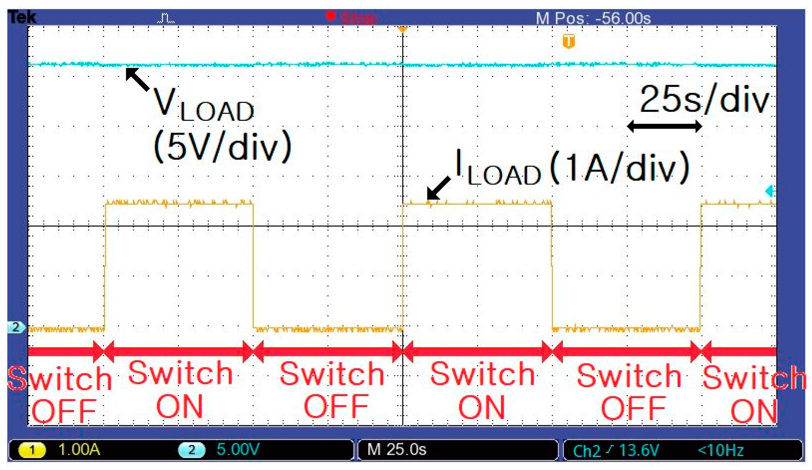
Figure 15 shows the voltage (VLOAD) and current (ILOAD) waveforms for changes in the load (2.5 A). Clearly, VLOAD (or battery voltage) is 27 V, even for a load of 15 Ω. Thus, it was confirmed that the proposed LED-battery power-conversion system stably follows load fluctuations.
5. Conclusions
An MIT-sensor-based OTP circuit for an LED-battery power-conversion system was proposed. The MIT sensor is cheaper than conventional thermo-couplers and NTC thermistors. An analysis of the characteristics of the MIT sensor showed that it had a resistance of 372.1 kΩ at 70 °C, that rapidly decreased to 44.49 Ω at 75 °C. An OTP circuit was proposed for expanding the MIT sensor. If the MIT sensor over-heats, the reference voltage of the OTP circuit is set to 5 V. Consequently, the main switch’s gate signal in the flyback converter is turned off, resulting in the output of the converter being blocked. This terminates the charging of the lithium-ion battery.
Furthermore, an LED-battery power-conversion system was proposed, in which the output current of the flyback converter returns to normal when the temperature changes from over-temperature to normal temperature. The proposed LED-battery power-conversion system with OTP effectively suppresses the over-temperature generation of lithium-ion batteries for outdoor-lighting. This power-conversion system is expected to help enhance the stability of lithium-ion batteries in photovoltaic power and renewable-energy-based systems. The results of this study will lead to the provision of OTP for lithium-ion batteries, thereby helping to secure battery stability for electric vehicles.
Funding
This research received no external funding.
Acknowledgments
The MIT sensor in this paper was provided by Kim, H.T. of ETRI. The authors also appreciate Kim, H.T. for the constructive comments that helped improved the quality of this paper.
Conflicts of Interest
The authors declare no conflict of interest.
References
- Dalla Costa, M.A.; Schuch, L.; Michels, L.; Rech, C.; Pinheiro, J.R.; Costa, G.H. Autonomous street lighting system based on solar energy and LEDs. In Proceedings of the IEEE International Conference on Industrial Technology (ICIT), Vina del Mar, Chile, 14–17 March 2010; IEEE: Piscataway, NJ, USA, 2010; pp. 1143–1148. [Google Scholar]
- Rani, B.I.; Ilango, C.S.; Nagamani, C. Control strategy for power flow management in a PV system supplying DC loads. IEEE Trans. Ind. Electron. 2013, 60, 3185–3194. [Google Scholar] [CrossRef]
- Wai-Keung, L.; Loo, K.H.; Siew-Chong, T.; Lai, Y.M.; Tse, C.K. Bilevel current driving technique for LEDs. IEEE Trans. Power Electron. 2009, 24, 2920–2932. [Google Scholar] [CrossRef]
- Liu, N.; Chen, Q.; Lu, X.; Liu, J.; Zhang, J. A charging strategy for PV-based battery switch station considering service availability and self-consumption of PV energy. IEEE Trans. Ind. Electron. 2015, 62, 4878–4889. [Google Scholar] [CrossRef]
- Hwu, K.I.; Yau, Y.T.; Lee, L.L. Powering LED using high-efficiency SR flyback converter. IEEE Trans. Ind. Appl. 2010, 47, 376–386. [Google Scholar] [CrossRef]
- Moon, S.C.; Koo, G.B.; Moon, G.W. A new control method of interleaved single-stage flyback AC-DC converter for outdoor LED lighting systems. IEEE Trans. Power Electron. 2013, 28, 4051–4062. [Google Scholar] [CrossRef]
- Arias, M.; Lamar, D.G.; Linera, F.F.; Balocco, D.; Diallo, A.A.; Sebastian, J. Design of a soft-switching asymmetrical half-bridge converter as second stage of an LED driver for street lighting application. IEEE Trans. Power Electron. 2012, 27, 1608–1621. [Google Scholar] [CrossRef]
- Cummings, S. South Korea Identifies Top 4 Causes for ESS Fires. Li-Ion Tamer. Available online: https://liiontamer.com/south-korea-identifies-top-4-causes-that-led-to-ess-fires/ (accessed on 12 June 2020).
- Mott, N.F. The basis of the electron theory of metals, with special reference to the transition metals. Proc. Phy. Soc. A 1949, 62, 416–421. [Google Scholar] [CrossRef] [Green Version]
- Mott, N.F. Metal-Insulator Transitions; Taylor & Francis: Abingdon, UK, 1990. [Google Scholar]
- Morin, F.J. Oxides which show a metal-to-insulator transition at the Neel temperature. Phys. Rev. Lett. 1959, 3, 34–36. [Google Scholar] [CrossRef]
- Imada, M.; Fukimori, A.; Tokura, Y. Metal-insulator transitions. Rev. Modern Phy. 1998, 70, 1039–1263. [Google Scholar] [CrossRef] [Green Version]
- Kim, H.T.; Kim, B.J.; Lee, Y.W.; Chae, B.G.; Yun, S.J.; Kang, K.Y. Hole-driven MIT theory, Mott transition in VO2, MoBRiK device. Phys. C Supercond. 2007, 460–462, 1076–1078. [Google Scholar] [CrossRef] [Green Version]
- Kim, H.T. Extension of the Brinkman-Rice picture and the Mott transition. Phys. C Supercond. 2000, 341–348, 259–260. [Google Scholar] [CrossRef] [Green Version]
- Kim, H.T.; Chae, B.G.; Youn, D.H.; Maeng, S.L.; Kim, G.O.; Kang, K.Y.; Lim, Y.S. Mechanism and observation of Mott transition in VO2-based two- and three-terminal devices. New J. Phys. 2004, 6, 1–19. [Google Scholar] [CrossRef] [Green Version]
- Chae, B.G.; Kim, H.T.; Youn, D.H.; Kang, K.Y. Abrupt metal-insulator transition observed in VO2 thin films induced by a switching voltage pulse. Phys. B Condens. Matter 2005, 369, 76–80. [Google Scholar] [CrossRef] [Green Version]
- Kim, H.T.; Lee, Y.W.; Kim, B.J.; Chae, B.G.; Yun, S.J.; Kang, K.Y.; Han, K.J.; Yee, K.J.; Lim, Y.S. Monoclinic and correlated metal phase in VO2 as evidence of the Mott transition: Coherent phonon analysis. Phys. Rev. Lett. 2006, 97, 266401. [Google Scholar] [CrossRef] [PubMed] [Green Version]
- Kim, B.J.; Lee, Y.W.; Chae, B.G.; Yun, S.J.; Oh, S.Y.; Kim, H.T. Temperature dependence of the first-order metal-insulator transition in VO2 and programmable critical temperature sensor. Appl. Phys. Lett. 2007, 90, 023515. [Google Scholar] [CrossRef] [Green Version]
- Wu, J. A Basic Guide to Thermocouple Measurements Texas Instruments Application Report SBAA274. September 2018. Available online: https://www.ti.com/lit/an/sbaa274/sbaa274.pdf?ts=1592008112556&ref_url=https%253A%252F%252Fwww.google.com%252F (accessed on 12 June 2020).
- TDK Electronics. NTC Thermistors Datasheet NTCG Series May 2009. Available online: https://www.jp.tdk.com/tefe02/eb221_ntcg.pdf (accessed on 12 June 2020).
- Wikipedia. Heat Detector. Available online: https://en.wikipedia.org/wiki/Heat_detector (accessed on 12 June 2020).
- International Standards Organization. ISO 7240-5:2018 Fire Detection and Alarm Systems. Available online: https://www.iso.org/standard/67759.html (accessed on 12 June 2020).
Figure 1.
The theory of metal-insulator-transition (MIT) [13]: (a) Mott insulator and (b) Inhomogeneous.
Figure 1.
The theory of metal-insulator-transition (MIT) [13]: (a) Mott insulator and (b) Inhomogeneous.
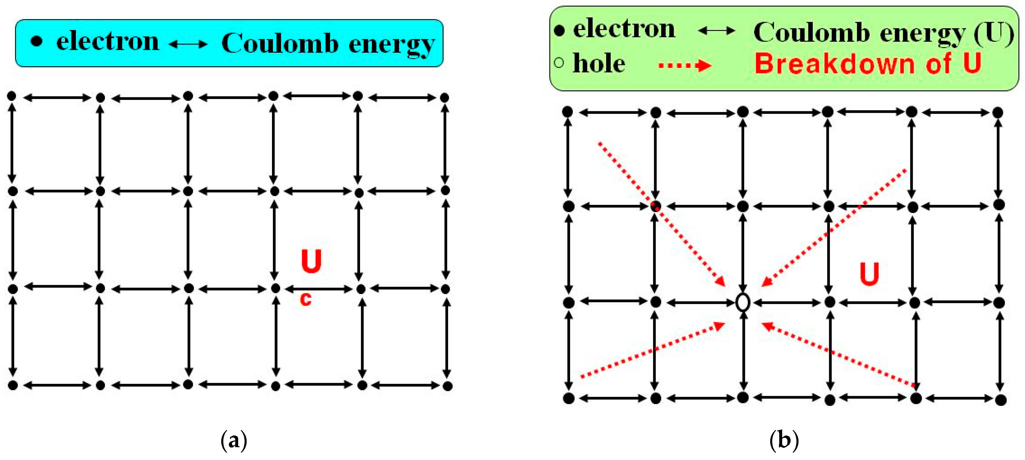
Figure 2.
Conventional and proposed temperature sensors: (a) thermo-coupler [19], (b) negative temperature coefficient (NTC) thermistor [20], and (c) MIT sensor [18].
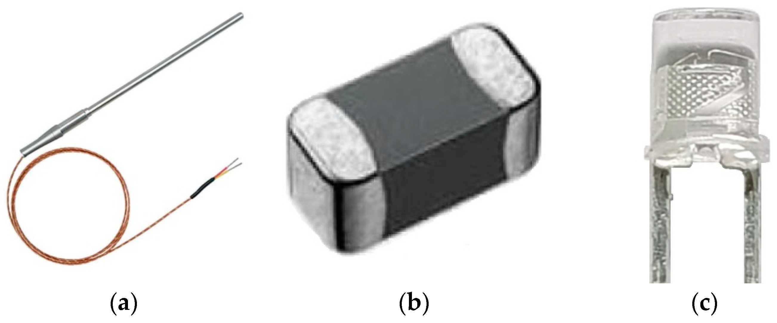
Figure 3.
Resistance variation according to temperature: (a) NTC thermistor [20,21,22] and (b) MIT sensor [15,18].

Figure 4.
Resistance measurement data for the MIT sensor.
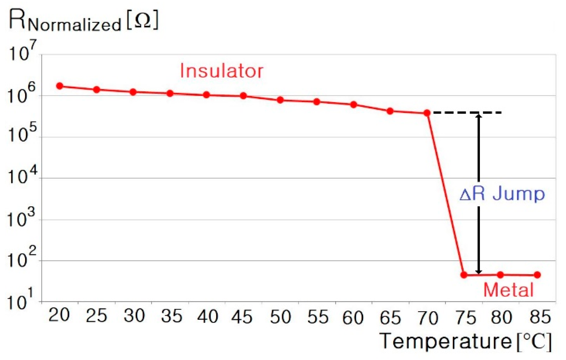
Figure 5.
The proposed lithium-ion battery system with a MIT sensor.
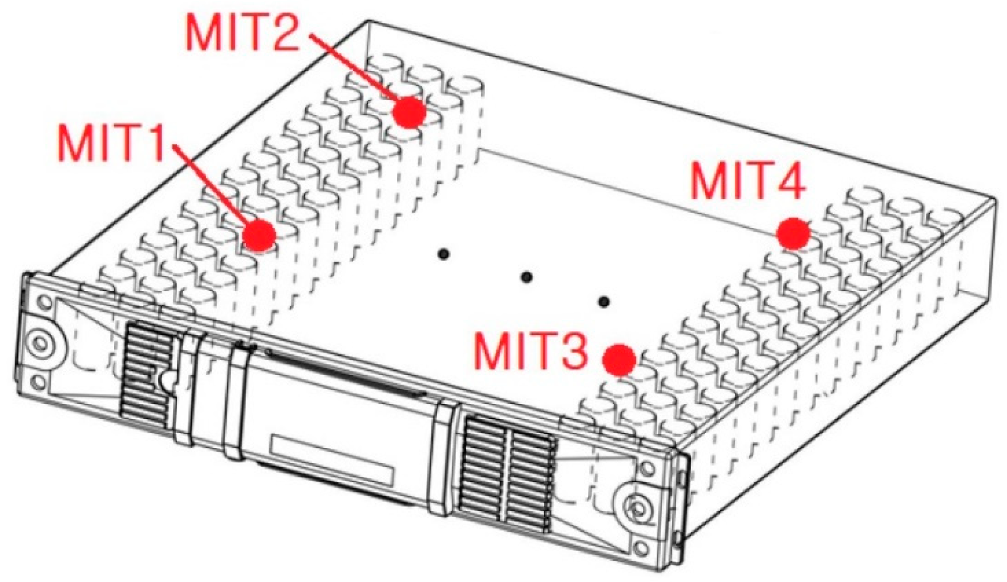
Figure 6.
The proposed LED-battery power-conversion system with an over-temperature-protection (OTP) circuit.
Figure 6.
The proposed LED-battery power-conversion system with an over-temperature-protection (OTP) circuit.
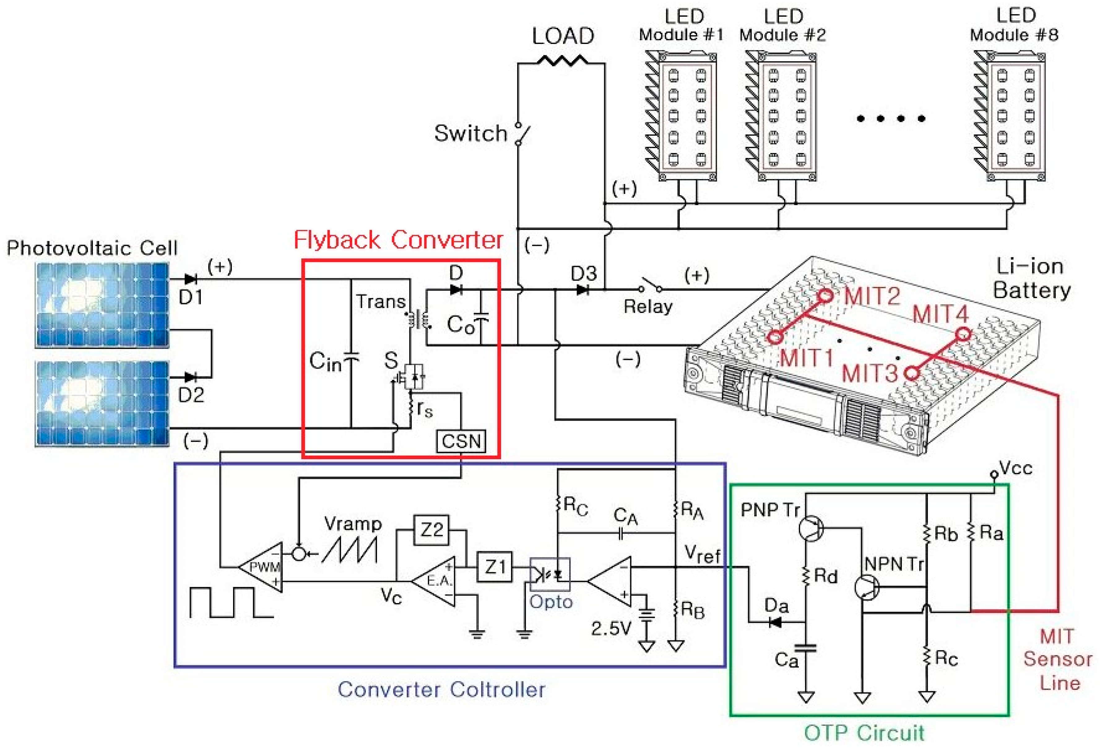
Figure 7.
The proposed OTP circuit.

Figure 8.
Experimental apparatus.
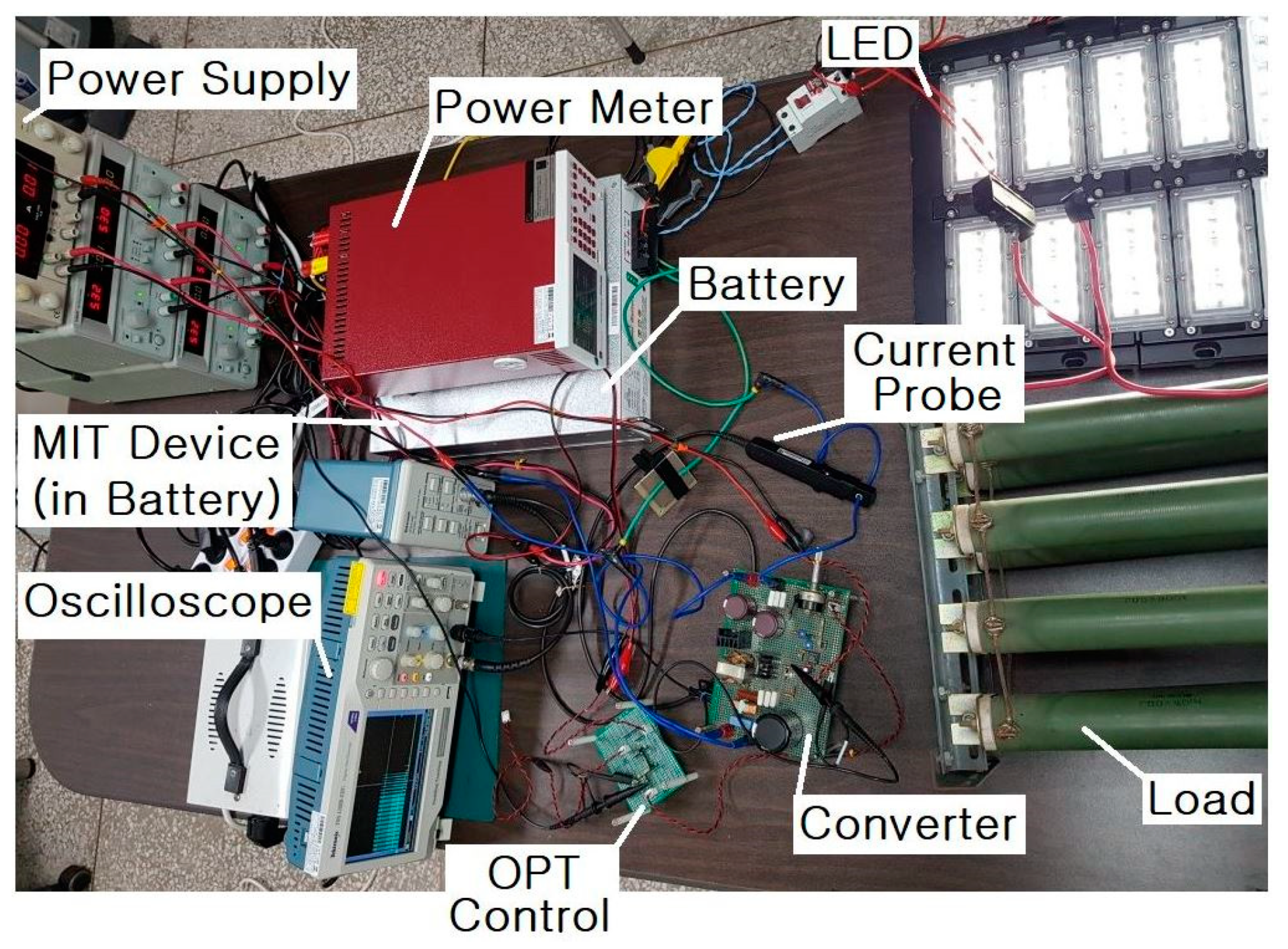
Figure 9.
Voltage (Vs) and current (Is) waveforms of the main switch (input 40 V, output 27 V/0.5 A).
Figure 9.
Voltage (Vs) and current (Is) waveforms of the main switch (input 40 V, output 27 V/0.5 A).

Figure 10.
Voltage (Vs) and current (Is) waveforms of the main switch (input 40 V, output 27 V/1 A).
Figure 10.
Voltage (Vs) and current (Is) waveforms of the main switch (input 40 V, output 27 V/1 A).
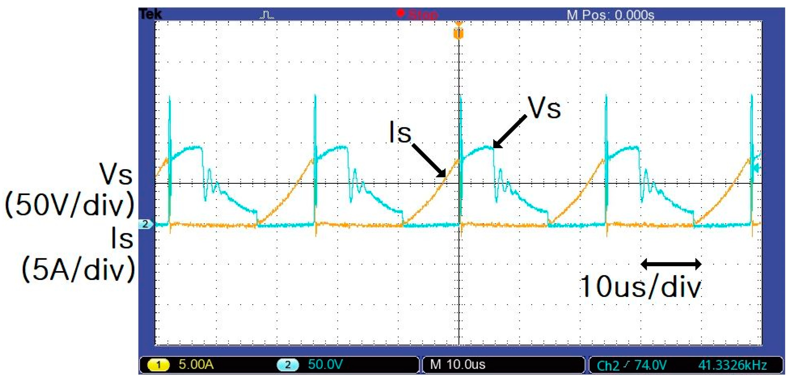
Figure 11.
Reference voltage (Vref) and the flyback converter output current (Io) when the temperature of the MIT sensor changed from normal to over-temperature (0.8 A).
Figure 11.
Reference voltage (Vref) and the flyback converter output current (Io) when the temperature of the MIT sensor changed from normal to over-temperature (0.8 A).
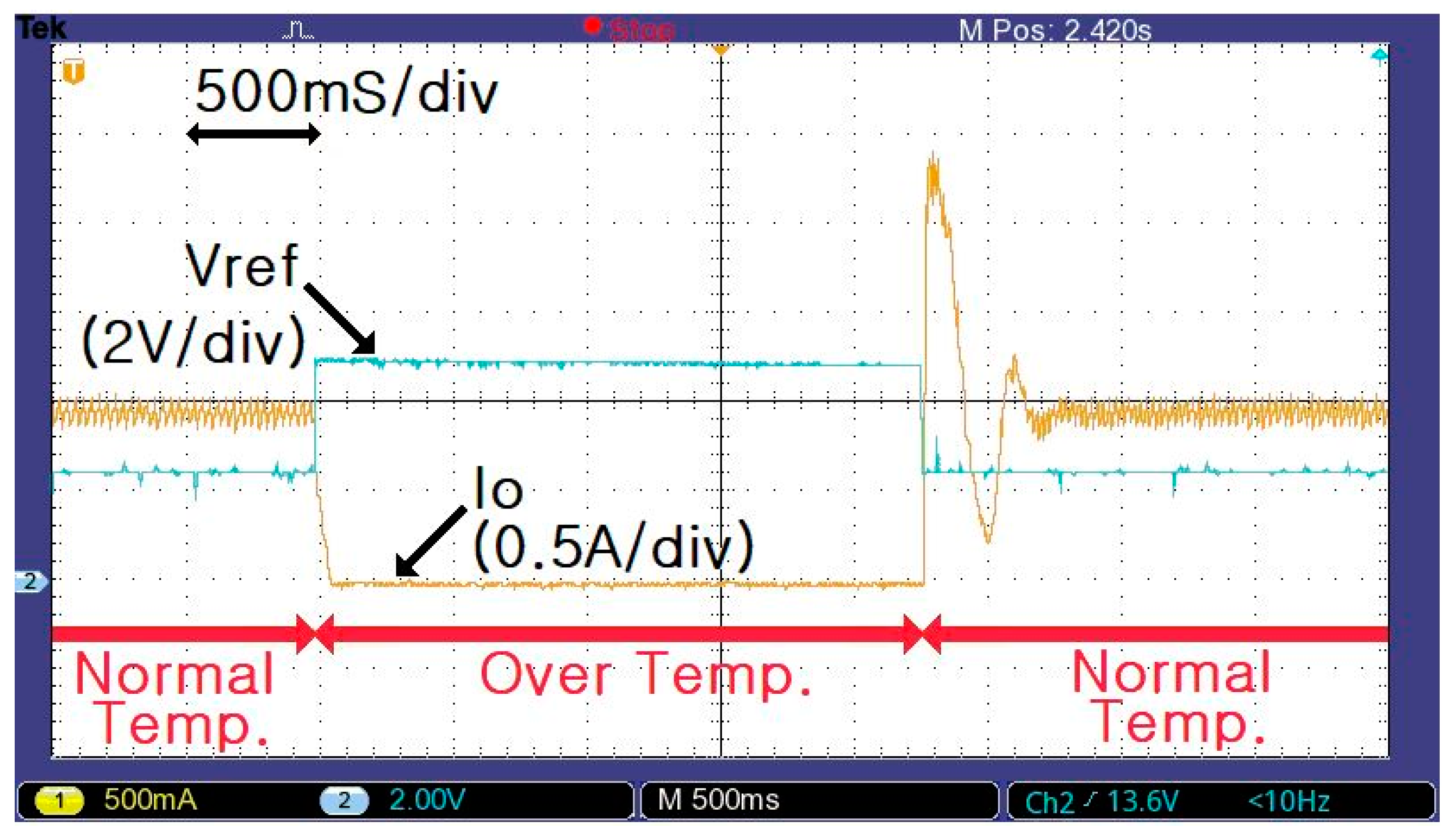
Figure 12.
Reference voltage (Vref) and the flyback converter output current (Io) when the temperature of the MIT sensor changed from normal to over-temperature (1.5 A).
Figure 12.
Reference voltage (Vref) and the flyback converter output current (Io) when the temperature of the MIT sensor changed from normal to over-temperature (1.5 A).
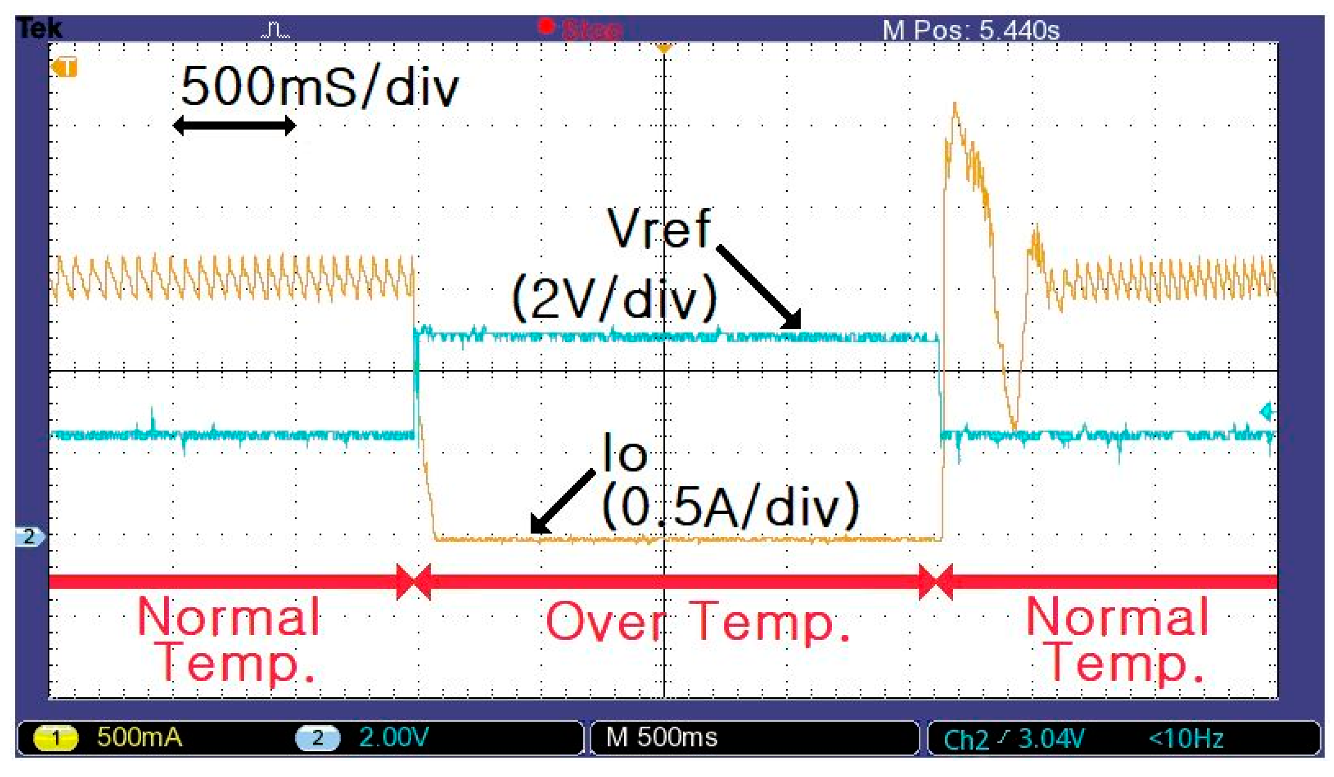
Figure 13.
Gate voltage (Vgate) and flyback converter output current (Io) when the temperature of the MIT sensor changed from normal to over-temperature (1.2 A).
Figure 13.
Gate voltage (Vgate) and flyback converter output current (Io) when the temperature of the MIT sensor changed from normal to over-temperature (1.2 A).

Figure 14.
Gate voltage (Vgate) and the flyback converter output current (Io) when the temperature of the MIT sensor changed from normal to over-temperature (1.2 A).
Figure 14.
Gate voltage (Vgate) and the flyback converter output current (Io) when the temperature of the MIT sensor changed from normal to over-temperature (1.2 A).
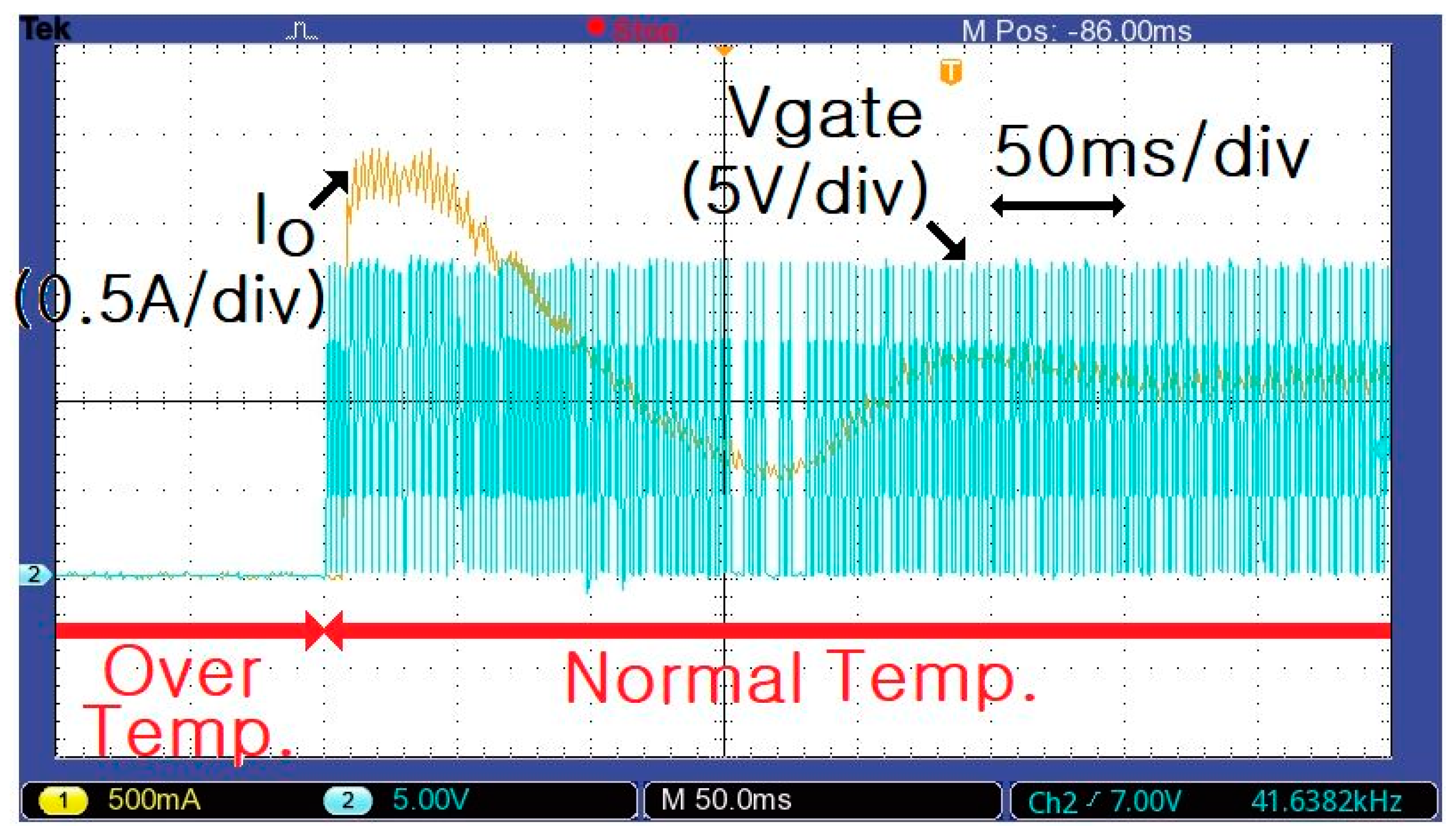
Figure 15.
Voltage (VLOAD) and current (ILOAD) waveforms for varying load (0–2.5 A).

Table 1.
Specifications and parameters of the LED-battery power conversion system.
| Device | Quantity | Value |
|---|---|---|
| Solar Cell (LG Ltd., LG250SIC-23, Two Series Connections) | Maximum Voltage | 29.9 V |
| Maximum Current | 8.27 A | |
| Flyback Converter (Prototype) | Input Voltage | 15–60 V DC |
| Output Voltage | 27 V DC | |
| Maximum Power | 50 W | |
| Main Switch | IRF640, Fairchild | |
| Diode | DSSK28-01A, IXYS | |
| Main Transformer | PQ2625, TDK 20: 10, = 25 µH | |
| Output Capacitor | 2000 µF | |
| 18650 Li-ion Battery (Samsung SDI Ltd.) | Operating Voltage | 21–28 V DC |
| Maximum Current | 15 A | |
| Maximum Capacity | 450 Wh | |
| Size | 297 × 85 × 335 mm | |
| LOAD | Non-inductive Bulk Resistance of 15 Ω | |
| LED Module (LG Innotek Ltd., Eight Parallel Connections) | Operating Voltage | 25–30 V DC |
| Maximum Current | 0.5 A | |
| Over-temperature Sensor (ETRI, MIT Sensor) | 120 nm thick VO2 film on an AlN/Si substrate | |
| MIT temperature: 70 °C | ||
© 2020 by the author. Licensee MDPI, Basel, Switzerland. This article is an open access article distributed under the terms and conditions of the Creative Commons Attribution (CC BY) license (http://creativecommons.org/licenses/by/4.0/).
Share and Cite
MDPI and ACS Style
Bae, J.-Y. Over-Temperature-Protection Circuit for LED-Battery Power-Conversion System Using Metal-Insulator-Transition Sensor. Energies 2020, 13, 3593. https://doi.org/10.3390/en13143593
AMA Style
Bae J-Y. Over-Temperature-Protection Circuit for LED-Battery Power-Conversion System Using Metal-Insulator-Transition Sensor. Energies. 2020; 13(14):3593. https://doi.org/10.3390/en13143593
Chicago/Turabian StyleBae, Jin-Yong. 2020. "Over-Temperature-Protection Circuit for LED-Battery Power-Conversion System Using Metal-Insulator-Transition Sensor" Energies 13, no. 14: 3593. https://doi.org/10.3390/en13143593
Note that from the first issue of 2016, this journal uses article numbers instead of page numbers. See further details here.