Effects of Injector Spray Angle on Performance of an Opposed-Piston Free-Piston Engine


School of Mechanical Engineering, Nanjing University of Science and Technology, Nanjing 210094, China
*
Author to whom correspondence should be addressed.
Energies 2020, 13(14), 3735; https://doi.org/10.3390/en13143735
Submission received: 12 June 2020
/
Revised: 15 July 2020
/
Accepted: 16 July 2020
/
Published: 20 July 2020
(This article belongs to the Section D: Energy Storage and Application)
Abstract
:A free-piston engine is a novel internal combustion engine which has the advantages of a variable compression ratio and multi-fuel adaptability. This paper focuses on numerical simulation for combustion process and spray angle optimization of an opposed-piston free-piston engine. The working principle and spray-guided central combustor structure of the engine are discussed. A three-dimensional computational fluid dynamic model with moving mesh is presented based on the tested piston motion of the prototype. Calculation conditions, spray models, and combustion models were set-up according to the same prototype. The effects of spray angle on fuel evaporation rate, mixture distribution, heat release rate, in-cylinder pressure, in-cylinder temperature, and emissions were simulated and analyzed in detail. The research results indicate that the performance of the engine was very sensitive to the spray angle. The combustion efficiency and the indicated thermal efficiencies of 97.5% and 39.7% were obtained as the spray angle reached 40°.
1. Introduction
The internal combustion engine (ICE) has been widely used in the automotive and aviation fields since its birth in 19th century and has been widely used in people’s daily lives. Its energy source is fossil fuel which is a non-renewable energy. As the automotive market continues to grow, the demand for ICE increases year-on-year, resulting in a rapid increase in demand for oil [1]. Meanwhile, the emissions from the ICE gradually increase the air pollution and greenhouse gas effect. The application of the ICE aggravates the energy crisis and environmental pollution, and that forces mankind to seek out solutions. The current development of the ICE is centered on a new energy engine, taking into account emissions requirements and comprehensively improving engine performance. On the one hand, researchers are trying to find alternative fuels to replace fossil fuel and reduce emissions [2]. On the other hand, they take into account that a new type of power plant can improve the fuel efficiency of conventional engines [3]. In recent years, more and more worldwide scholars pay attention to the free-piston engine which is a novel ICE. Compared with the conventional engine, the free-piston engine eliminates the crankshaft and connecting rod mechanism, and the piston is free to move among its endpoints, only determined by the forces acting on it. Therefore, the free-piston engine can operate with various compression ratios, and it brings potential advantage such as multi-fuel adaptability which means that the free-piston engine can adopt clean fuels, not only solving the energy crisis, but also reducing emissions [4,5]. Due to the fact of its particular structure, the free-piston engine also has the merits of simple structure, low manufacturing cost, high efficiency, multi-combustion mode flexibility as well as high power density [6,7].
In this study, an opposed piston-type free-piston engine with direct injection was applied in terms of its various merits. It is well-known that the fuel direct injection system leads to higher fuel efficiency [8]. Due to the special geometric structure of the central combustor of the engine, it has higher requirements on injection. With the narrow structure, the atomization of the fuel spray is limited, which affects the mixture formation significantly. In addition, the small central combustor restricts the spray penetration distance, and it will intensify the impingement phenomenon with long penetration distance. Overall, the injection system of a free-piston engine needs further study to achieve better spray performance.
Researchers have done a lot of work on the spray process of the engine. Prabhakara et al. [9] focused on researching the effect of injection pressure on spray process. The results indicated that higher injection pressure is favorable for better fuel atomization and better combustion. However, this finding lacks tested results which should be compared with simulation results. Yuan et al. [10] investigated the spray characteristics of a free-piston engine by comparing with a conventional engine. They found that the spray fuel in a free-piston engine shows smaller sauter mean diameter (SMD) and higher concentration around the spark plug, which is good for mixture formation than a conventional engine. Guo et al. [11] indicated that the trends of the peak in-cylinder pressure versus the injection timing were identical with the convex function curve, and the trapezium fuel injection rate-profile is more appropriate and can keep high efficiency of a free-piston engine than other injection rate-profiles; nevertheless, they did not provide the parameters of the combustion process in detail.
Most of the articles, including the above, did not provide the combustion characteristics clearly, and some of those did not compare the calculation results with the tested results which leads to difficulties of validating the models [12,13,14,15,16]. Furthermore, numerous documents mainly studied how the injection timing, injection pressure, as well as injection rate in the spray process affect the performance of the engine. However, studies on the effects of the spray angle on the spray process is still scarce. In fact, the spray angle is one of the key parameters which affect mixture formation and combustion efficiency of the engine, and it has influence on fuel economy and emission properties indirectly [17]. Hence, further study is still necessary regarding the effects of spray angle on the performance of the engine.
This paper focuses on numerical simulation for spray angle optimization of an opposed-piston free-piston engine. First, the working principle and spray-guided central combustor structure of the engine are discussed. Then, the computational fluid dynamics (CFD) model of the central combustor was established based on the tested piston motion of the prototype. Finally, the effects of spray angle on performance of the free-piston engine were simulated and analyzed in detail. The results obtained in this paper provide a useful guidance for the improvement of the opposed-piston free-piston engine.
2. System Description
2.1. Working Principle of the Engine
The free-piston engine coupled with linear generator (FPEG), as a novel energy conversion device, can convert the chemical energy of fuels to electric energy [18]. The elementary structure of the opposed-piston FPEG prototype is shown in Figure 1. It consists of one central combustor, two air-springs, and two linear generators, and the overall structure is centrally symmetrical. Furthermore, the opposed-piston central combustor is equipped with a spark plug and fuel injector. The piston on each side is connected directly to the mover of the linear generator. Due to the elimination of the crankshaft and connecting rod mechanism, the piston assembly moves between inner dead center (IDC) and outer dead center (ODC) without restriction, and its motion is determined by the resultant force acting on the mover.
In the FPEG system, a complete working cycle consists of two strokes including expansion stroke and compression stroke. During the expansion stroke, the fuel mixture is ignited by the spark plug, and the gas generated in combustion process pushes the piston assembly to move from IDC to ODC, and the air is sucked into the cylinder to accomplish the gas exchange process. Meanwhile, the air-spring is compressed to store energy for the next stroke. During the compression stroke, the expansion of the air-spring releases the stored energy, and the piston assembly moves towards IDC compressing the in-cylinder mixture [19]. Most of the time, the linear generator works in the generating mode because the engine works in the combustion cycle. The linear generator works in motoring mode only in the starting time or no-fire cycle of the engine.
2.2. Central Combustor of the Engine
Figure 2 shows the structure of the central combustor discussed in this paper. It consists of two opposed pistons, two intake ports, two exhaust ports, one spark plug, and one fuel injector. The shape of piston top is one of the key factors affecting spray and combustion processes, and it has an effect on the gas flow, fuel atomization, and flame propagation in the cylinder [20]. The piston is designed as a flat-topped piston due to the fact of its advantages of large combustor volume, uniform force, small heat absorption area, simple structure, and easy processing. In order to obtain higher gas exchange efficiency, the central combustor is equipped with two intake and exhaust ports, which can increase intake flow and reduce backflow phenomenon.
In Figure 2, xin and xex represent the distance from intake port and exhaust port to the center of the combustor, respectively. In order to improve the gas exchange process, the position of the exhaust port and the width of the intake port are adjusted. By gradually increasing xex, it was found that the change in the exhaust port position had a slight influence on the gas exchange efficiency. With the width of the intake port increasing, the gas exchange efficiency increases, but the gas exchange duration also increases. From the perspective of the entire working cycle, longer gas exchange duration results in shorter combustion duration, which causes the combustion efficiency decrease. In the end, the main structure parameters of the central combustor are listed in Table 1.
The central combustor is also equipped with one spark plug and one fuel injector which can provide accurate injection duration and fuel supply. This engine adopts the gasoline direct injection (GDI) system to achieve lean combustion and conserve fuel accordingly. During lean combustion, direct injection system reduces pumping loss. Because the directly injected fuel is more likely to impinge on the piston and cylinder wall, the air-guided direct injection system and the wall-guided direct injection system have disadvantages of low fuel efficiency and unfavorable emissions. Therefore, the engine in this paper adopted a spray-guided direct injection system to avoid the disadvantages mentioned above. For the spray-guided stratified direct injection system, the fuel injector and the spark plug were close-spaced, and the fuel injector confined the spray fuel reducing contact with the piston, so it was easier to form a proper ignitable mixture near the spark plug to improve combustion and emissions. Clearly, the combustion process depends more on the spray characteristics of the injection system than on the in-cylinder air flow [21].
3. CFD Model
3.1. Mesh Model of the Engine
At present, most researchers apply a zero-dimensional or one-dimensional procedure to simulate the free-piston engine. These models neglect the air flow and the fuel distribution in the cylinder, so it is difficult to define the initial and boundary conditions causing the calculation results to be inaccurate.
In this paper, a three-dimensional CFD model was established in AVL-Fire which is a commercial software to calculate the entire working cycle of the free-piston engine. Piston motion curve is one of the basic conditions for calculation. As can be seen, the working process of one cycle is divided into two stages including compression stroke and expansion stroke. Figure 3 shows the piston motion curve with the specific open and close times of intake and exhaust ports. The equivalent crank angle (ECA) instead of the time variable was employed to describe the motion time. To obtain this curve, first, a computation model of the free-piston engine is built in MATLAB/Simulink. Then, the force output from the sub-models, such as the cylinder and linear generator, was used as input. Under the control and conversion of the sub-models, the force situation and motion trajectory of the engine piston were analyzed. The main ECA of the engine is listed in Table 2.
Based on the CFD software AVL-Fire, a mesh model of central combustor was established in this paper. As shown in Figure 4, the mesh model consisted of two intake ports, two exhaust ports, and a cylinder, and the whole computational mesh was centrally symmetrical. The computational meshes of the connection sections between the intake and exhaust ports and the cylinder were encrypted to obtain sufficient fine meshes, eliminating the grid effects and increasing the accuracy of the calculation results. The mesh size was the primary factor affecting calculation results. The smaller mesh size makes higher accuracy but takes a longer calculating time. In the process of the mesh established, the meshes were of hexahedral structure with a maximal cell size of 1 mm which can ensure the stability of the computation and save calculation time.
In the moving mesh tool Fame Engine, there are two options to define the free-piston movement. One is to set the piston displacement function (connecting rod, stroke, and piston offset). The other, which is adopted in the paper, was to import a readable data file. The data file had two columns of numbers: one column was the ECA and the other was the piston displacement. After importing the data file and defining the directions of the opposed pistons, the computation software creates the moving mesh model. As shown in Figure 4a,b, there are two moving surfaces on each piston moving between IDC and ODC.
3.2. Calculation Conditions of the Engine
Before calculation starts, it is necessary to set-up the initial conditions and boundary conditions. The calculation starts at the exhaust ports’ open time (80 °CA) and ends at exhaust ports’ open time of next cycle (440 °CA). Table 3 lists the initial conditions and boundary conditions tested from the prototype such as pressure and temperature at 80 °CA.
A series of sub-models in the CFD software was employed to describe the spray and combustion process clearly in the free-piston engine. Turbulent flow was the disordered airflow in the cylinder, and it affected the mixture formation, flame propagation, and heat transfer in the cylinder. The k-ε model was chosen as turbulence model to calculate the in-cylinder airflow. k represents turbulent kinetic energy, and ε represents diffusion rate of turbulent kinetic energy. The k-ε model is widely used in engineering applications due to the fact of its good adaptability and calculation stability [22].
The spray process is one of the indispensable stages in the cylinder. It has a significant effect on the fuel atomization, evaporation and mixing process, so it directly determines the quality of the combustion process. This paper adopts an outer open-loop injector whose needle valve opens outward, and the fuel is injected from the gap between the needle valve forming an umbrella spray. The outer diameter and inner diameter of the nozzle were 3.80 mm and 3.76 mm, respectively. As shown in Figure 5, the whole spray process consisted of four stages including spray, breakup, evaporation, and wall interaction. The Taylor analogy breakup (TAB) model was used as the breakup model due to the fact of its suitability for hollow cone spray, and it is based on the theory of elastic mechanics which means the droplets will break up when vibrating and twisting to a certain extent.
Equation (1) shows the governing equation of droplets oscillation deformation:
where is the displacement of the droplets; and represent the gas and liquid density; is the relative velocity of the droplets; is the radius of the droplets; is the gas–liquid surface tensions; represents the viscosity of the liquid; , , , and are dimensionless constants [23].
The fuel evaporation process involves gas–liquid two-phase flow which is complicated and has a significant effect on the gas formation. The Dukowicz model is adopted as evaporation model due to the fact of its advantage of low calculation cost to describe the mass and heat transfer of fuel evaporation. This model is based on the following assumptions: (1) the droplets are spherical symmetry; (2) quasi steady gas-film around the droplet; (3) uniform droplet temperature along the droplet diameter; (4) uniform physical properties of the surrounding fluid; (5) liquid–vapor thermal equilibrium on the droplet surface. This model assume that the temperature of the droplets is uniform, so the rate of droplets temperature change is determined by the energy balance equation:
where means the mass of droplets; is the drag coefficient; is the temperature of droplets; represents the convective heat transfer coefficient through the film around the droplets; is the area of the droplets surface; means the far-field temperature; is the temperature of droplets surface [24].
The Walljet1 model is employed as the wall interaction model due to the fact of its suitability for heated walls, and it ignores the mass exchange with oil film on the cylinder wall [25]. The Schmidt model is used as the particle interaction model which has advantages of high computational efficiency and low grid sensitivity [26]. The selected sub-models in the spray process are listed in Table 4.
For the simulation on spark ignition engines, there are several different ignition models. The coherent flame model was applied as the flame model in this paper. The initial flame core of the coherent flame model was spherical. This model had the merit of good adaptability which can be used in combination with multiple combustion models. The in-cylinder combustion process of the engine was actually a complex turbulent combustion process with various chemical reactions. The common combustion model was set to simplify the complicated chemical reaction process and decompose it to corresponding reaction equations to calculate. The extended coherent flame model (ECFM) is suitable for simulating the combustion process of the spark-ignition engine, so it was adopted in the paper [27]. Table 5 lists the flame model and parameters used in the paper.
3.3. Validation of Spray Models
Choosing suitable spray models and determining their parameters are extremely important for simulating the spray process of the free-piston engine. Therefore, it is significant to validate and verify the spray models mentioned in Table 4. The validation of the fuel injection model was performed using Jose’s experimental data [28]. The initial calculation parameters of spray process are listed in Table 6. Figure 6 shows the tested results and simulation results of spray shape at 1.5 bar ambient pressure and 293 K ambient temperature. It is obvious that the simulated spray morphology was in great agreement with the experimental results. Consequently, the above spray models are appropriate for simulating spray process of the free-piston engine.
4. Results and Discussions
4.1. Effects of Spray Angle on Spray Process
To clearly illustrate the effects of spray angle on spray process, five spray angles θ (30°, 35°, 40°, 45°, 50°) were investigated by CFD method in this paper. The initial parameters of the spray process were set according to Table 6. Figure 7 shows the fuel evaporation rate of different spray angles in the spray process. It can be seen that the fuel evaporation rate had all reached above 99% at ignition time (340 °CA), and the highest fuel evaporation rate was 99.8% when the spray angle reached 40°. It is obvious that the spray angle had a slight influence on the fuel evaporation rate. Figure 8 shows the SMD of in-cylinder droplets of different spray angles. It can be found that after being discharged into the cylinder, the fuel breaks into small droplets, and those small droplets come together over time, so the SMD curve first decreased and then increased. At ignition time, the SMD reduced first then increased as the spray angle increased from 30° to 50°. Figure 8 is consistent with the results shown in Figure 7, because smaller SMD results in a higher evaporation rate [29].
The whole spray process mainly includes the fuel injection process and the mixture formation process. In order to get better combustion, the fuel/air ratio around the spark plug should be appropriate (which is about 1.2), and that can facilitate flame propagation and combustion. If the fuel concentration around the spark plug is too high, a large amount of carbon monoxide (CO) and nitrogen oxide (NOx) are generated due to the incomplete combustion. With the lean mixture around the spark plug, the flame propagation time is longer and the combustion speed decreases. On account of the spray-guided direct injection system, the fuel is easier to gather around the spark plug at a smaller spray angle. Figure 9 shows the fuel/air ratio of different spray angles at 340 °CA. It can be found from the figure that as the spray angle was less than 40°, the fuel was mainly concentrated in the lower part of the cylinder, while the fuel mainly accumulated in the upper part of the cylinder as the spray angle was more than 40°. In addition, the fuel concentration near the spark plug became lower when the spray angle increased from 30° to 50°.
4.2. Effects of Spray Angle on Combustion Process
The heat release rate (HRR) of different spray angles is shown in Figure 10. It is noticed that the HRR has one peak, and as the spray angle increased, the peak of the HRR appeared earlier and increased first then decreased. It also can be found that the heat release of the smaller spray angle was faster in the early stage of the combustion process. The peak of the HRR achieved the highest value by 14.5 J/°CA when the spray angle was 35°. As the spray angle increased from 35° to 50°, the peak of the HRR decreases, and the heat release process became longer. This phenomenon results from that on one side, the injected fuel of a larger spray angle was more likely to concentrate on moving piston when the piston moves to IDC, thereby affecting the diffusion of spray fuel and heat release process. On the other side, the fuel concentration in the upper part of the cylinder increased along with the increasing spray angle, which also makes combustion difficult.
Figure 11 depicts the in-cylinder pressures of different spray angles. It can be observed that the peak pressure appeared around a crank angle of 365–370 °CA. The peak pressure was delayed along with the growing spray angle. When the spray angle was less than 45°, the spray angle had little effect on peak pressure, and the highest pressure was 69 bar. When the spray angle was more than 45°, the peak in-cylinder pressure was more sensitive to the spray angle, indicating that the combustion speed had a decrease as shown in Figure 10.
Figure 12 presents the in-cylinder fuel distribution of different spray angles at the time of exhaust port open. It is clear that as the spray angle increased, the residual fuel was distributed around the cylinder instead of gathering in the upper part of the cylinder. As the spray angle reached 40° or 45°, the area of unburnt fuel in the cylinder was small.
4.3. Effects of Spray Angle on Combustion Characteristics
For the purpose of describing the effects of spray angle on the engine performance in detail, the main combustion characteristics of different spray angles are shown in Figure 13 and Figure 14. In these figures, CA10, CA50, and CA90 are defined as the position of the crank angle at 10%, 50%, and 90% of accumulated heat release which can be explained by Equations (4)–(6); CA10–CA90 represents the combustion duration.
where means crank angle; represents the maximum of the accumulated heat release.
As shown in Figure 13, when the spray angle increased CA50 obviously delayed, and when the spray angle was 45°, CA50 was located in the optimal position which was approximately 5 °CA after inner dead center (AIDC). Moreover, with the increase in the spray angle, CA10–CA90 decreased first and then increased. The results are attributed to the following. When the spray angle is less than 40°, the high concentration of the mixture around the spark plug causes incomplete combustion. While the spray angle is more than 45°, most of fuel gathers in the upper part of the cylinder hindering flame propagation and decreasing combustion speed, and some fuel is easier to collide with the moving piston. All these results in longer combustion duration. When the spray angle reaches 40° or 45°, the combustion speed is faster resulting in shorter combustion duration and higher efficiency.
The combustion efficiency and the indicated thermal efficiency are shown in Figure 14 to present the dynamic performance. This article adopted Equations (7) and (8) to define combustion efficiency and indicated thermal efficiency:
where and represents the combustion efficiency and indicated thermal efficiency respectively; as the accumulated heat release; as the low heating value of fuel; is the mass of the fuel injected in the cylinder; represents the work of piston; represents the heat released from fuel burnt.
It is obvious that the best combustion efficiency was located at the spray angle of 40°, and the indicated thermal efficiency of that spray angle also achieved the highest value. It can be found that the spray angle had a greater effect on combustion efficiency and indicated thermal efficiency. The exhaustive parameters of Figure 13 and Figure 14 are listed in Table 7.
4.4. Effects of Spray Angle on Emissions
The CO emissions, one of the main factors to describe the engine performance, are discussed below. The CO distribution of different spray angles at 440 °CA is shown in Figure 15. Clearly, as the spray angle increased from 30° to 40°, the CO was distributed around the cylinder, and it was distributed in the upper part of the cylinder as the spray angle continued to increase.
Figure 16 displays CO emissions curve in detail. It shows that at 440 °CA, the CO emissions decreased first then increased, as the spray angle increased from 30° to 50°. This phenomenon can be explained as follows. The CO is sensitive to fuel/air ratio and temperature. It can be seen from Figure 9, that as the spray angle increased from 30° to 40°, the mixture around the spark plug became thinner, so the CO emissions decreased. But when the spray angle continued to increase, the fuel mainly accumulated in the upper part of the cylinder. High concentration of the mixture promotes CO production, so the CO emissions increase as the spray angle increases from 40° to 50°. Another reason is that when the spray angle increases, the in-cylinder temperature rises first and then decreases, which is shown in Figure 17. The CO is mainly produced by Reaction (9) and consumed by Reaction (10). In addition, Reaction (10) is dependent on the in-cylinder temperature and requires particularly high energy [20]. But at a higher temperature, it is easier to promote NOx formation. It is difficult to transform CO to carbon dioxide (CO2) at a lower temperature. It can be seen that the spray angle had a slight influence on the in-cylinder temperature as the spray angle was less than 50°. Therefore, the temperature was not the dominant reason why the CO emissions were high. It is easy to find that the CO emissions achieve the lowest value when the spray angle is 40°.
5. Conclusions
The effects of injector spray angle on performance of an opposed-piston free-piston engine is investigated and optimized by using CFD method in this study. Working principle and spray-guided central combustor structure of the engine are discussed. The CFD model with moving mesh is established based on piston motion of the prototype. According to the simulated results, the effects of spray angle on spray process, combustion process, combustion characteristics, and emissions of the free-piston engine were analyzed in detail. The conclusions are as follows:
- (1)
- The spray angle had a slight influence on the fuel evaporation rate;
- (2)
- When the spray angle increased, the fuel concentration near the spark plug decreased, and that in the upper part of the cylinder became higher;
- (3)
- The heat release of smaller spray angle was faster in the early stage of the combustion process;
- (4)
- The peak in-cylinder pressure kept minor fluctuations as the spray angle was less than 45°, and it decreased when the spray angle reached 50°;
- (5)
- As the spray angle reached 40°, the combustion efficiency and indicated thermal efficiency achieve the highest value of 97.5% and 39.7% compared with other spray angles (30°, 35°, 45°, 50°);
- (6)
- From an emissions perspective, CO emissions decreased first and then increased with increasing spray angle. When the spray angle was 40°, the CO emissions achieved the lowest value. In order to obtain a better performance and keep lower CO emissions, the optimal spray angle should be approximately 40°.
Further study is still essential to achieve energy savings and higher efficiency of the free-piston engine. In the next stage, the performance of the free-piston engine will be improved by optimizing the intake and exhaust system.
Author Contributions
Supervision, Z.X. and L.L.; Investigation, Software, Original draft—editing, Q.Z.; Writing—review, S.L. All authors have read and agreed to the published version of the manuscript.
Funding
This work was supported by the National Natural Science Foundation of China (Grant No. 51875290 and No. 51975297).
Conflicts of Interest
The authors declare no conflict of interest.
References
- Lee, C.H.; Reitz, R.D. CFD simulations of diesel spray tip penetration with multiple injections and with engine compression ratios up to 100:1. Fuel 2013, 111, 289–297. [Google Scholar] [CrossRef]
- Niculae, A.L.; Miron, L.; Chiriac, R. On the possibility to simulate the operation of a SI engine using alternative gaseous fuels. Energy Rep. 2020, 6, 167–176. [Google Scholar] [CrossRef]
- Wang, Q.; Wu, F.; Zhao, Y.; Bai, J.; Huang, R. Study on combustion characteristics and ignition limits extending of micro free-piston engines. Energy 2019, 179, 805–814. [Google Scholar] [CrossRef]
- Yuan, C.; Han, C.; Xu, J. Numerical evaluation of pilot-ignition technology used for a hydrogen fuelled free piston engine generator. Int. J. Hydrogen Energy 2017, 42, 28599–28611. [Google Scholar] [CrossRef]
- Sofianopoulos, A.; Zhou, Y.; Lawler, B.; Mamalis, S. Gas exchange processes of a small HCCI free piston engine—A computational study. Appl. Therm. Eng. 2017, 127, 1582–1597. [Google Scholar] [CrossRef]
- Feng, H.; Guo, C.; Yuan, C.; Guo, Y.; Zuo, Z.; Roskilly, A.P.; Jia, B. Research on combustion process of a free piston diesel linear generator. Appl. Energy 2016, 161, 395–403. [Google Scholar] [CrossRef]
- Geng, H.; Wang, Y.; Xi, B.; Li, Z.; Zhen, X.; Fu, C.; Hu, Y. Study on HCCI combustion improvement by using dual assisted compression ignition (DACI) on a hydraulic free piston engine fueled with methanol fuel. Appl. Therm. Eng. 2020, 167, 114782. [Google Scholar] [CrossRef]
- Duronio, F.; De Vita, A.; Montanaro, A.; Villante, C. Gasoline direct injection engines—A review of latest technologies and trends. Part 2. Fuel 2020, 265, 116947. [Google Scholar] [CrossRef]
- Raju, V.R.K.; Rao, S.S. Effect of Fuel Injection Pressure and Spray Cone Angle in DI Diesel Engine Using CONVERGETM CFD Code. Procedia Eng. 2015, 127, 295–300. [Google Scholar] [CrossRef] [Green Version]
- Yuan, C.; Liu, Y.; Han, C.; He, Y. An investigation of mixture formation characteristics of a free-piston gasoline engine with direct-injection. Energy 2019, 173, 626–636. [Google Scholar] [CrossRef]
- Guo, C.; Song, Y.; Feng, H.; Zuo, Z.; Jia, B.; Zhang, Z.; Roskilly, A. Effect of fuel injection characteristics on the performance of a free-piston diesel engine linear generator: CFD simulation and experimental results. Energy Convers. Manag. 2018, 160, 302–312. [Google Scholar] [CrossRef] [Green Version]
- Huang, H.; Guo, X.; Huang, R.; Li, J.; Pan, M.; Chen, Y.; Pan, X. Assessment of n-pentanol additive and EGR rates effects on spray characteristics, energy distribution and engine performance. Energy Convers. Manag. 2019, 202, 112210. [Google Scholar] [CrossRef]
- Shrivastava, P.; Verma, T.N. Effect of fuel injection pressure on the characteristics of CI engine fuelled with biodiesel from Roselle oil. Fuel 2020, 265, 117005. [Google Scholar] [CrossRef]
- Shi, Z.; Lee, C.-F.; Wu, H.; Li, H.; Wu, Y.; Zhang, L.; Bo, Y.; Liu, F. Effect of injection pressure on the impinging spray and ignition characteristics of the heavy-duty diesel engine under low-temperature conditions. Appl. Energy 2020, 262, 114552. [Google Scholar] [CrossRef]
- Shi, L.; Ji, C.; Wang, S.; Su, T.; Cong, X.; Wang, D.; Tang, C. Effects of second injection timing on combustion characteristics of the spark ignition direct injection gasoline engines with dimethyl ether enrichment in the intake port. Energy 2019, 180, 10–18. [Google Scholar] [CrossRef]
- Han, T.; Singh, R.; Lavoie, G.; Woolridge, M.S.; Boehman, A.L. Multiple injection for improving knock, gaseous and particulate matter emissions in direct injection SI engines. Appl. Energy 2020, 262, 114578. [Google Scholar] [CrossRef]
- Shu, J.; Fu, J.; Liu, J.; Ma, Y.; Wang, S.; Deng, B.; Zeng, D. Effects of injector spray angle on combustion and emissions characteristics of a natural gas (NG)-diesel dual fuel engine based on CFD coupled with reduced chemical kinetic model. Appl. Energy 2019, 234, 182–195. [Google Scholar] [CrossRef]
- Shmelev, V. An internal combustion alternator with both free piston and cylinder. Eng. Sci. Technol. Int. J. 2019, 22, 947–955. [Google Scholar] [CrossRef]
- Jia, B.; Mikalsen, R.; Smallbone, A.; Roskilly, A.P. A study and comparison of frictional losses in free-piston engine and crankshaft engines. Appl. Therm. Eng. 2018, 140, 217–224. [Google Scholar] [CrossRef]
- Yu, H.; Xu, Z.; Zhang, Q.; Liu, L.; Hua, R. Two-Stroke Thermodynamic Cycle Optimization of a Single-Cylinder Free-Piston Engine Generator. Adv. Mater. Sci. Eng. 2019, 2019, 1–11. [Google Scholar] [CrossRef] [Green Version]
- Ciampolini, M.; Bigalli, S.; Balduzzi, F.; Bianchini, A.; Romani, L.; Ferrara, G. CFD Analysis of the Fuel–Air Mixture Formation Process in Passive Prechambers for Use in a High-Pressure Direct Injection (HPDI) Two-Stroke Engine. Energies 2020, 13, 2846. [Google Scholar] [CrossRef]
- Saaidia, R.; Jemni, M.A.; Abid, M.S. Simulation and Empirical Studies of the Commercial SI Engine Performance and Its Emission Levels When Running on a CNG and Hydrogen Blend. Energies 2017, 11, 29. [Google Scholar] [CrossRef] [Green Version]
- O’Rourke, P.J.; Amsden, A.A. The Tab Method for Numerical Calculation of Spray Droplet Break-Up; SAE Paper 872089; SAE: Warrendale, PA, USA, 1987; Volume 87, pp. 1–10. [Google Scholar]
- Dukowicz, J.K. A particle-fluid numerical model for liquid sprays. J. Comput. Phys. 1980, 35, 229–253. [Google Scholar] [CrossRef]
- Naber, J.; Reitz, R.D. Modeling Engine Spray/Wall Impingement. SAE Tech. Pap. Ser. 1988, 88, 118–140. [Google Scholar] [CrossRef]
- O’Rourke, P.J. Statistical properties and numerical implementation of a model for droplet dispersion in a turbulent gas. J. Comput. Phys. 1989, 83, 345–360. [Google Scholar] [CrossRef]
- Nishida, K.; Hiroyasu, H. Simplified Three-Dimensional Modeling of Mixture Formation and Combustion in a D.I. Diesel Engine. SAE Tech. Pap. Ser. 1989, 1, 276–293. [Google Scholar] [CrossRef]
- Jose, R.I.; Cervantes, T. Direct Injection System for a Two Stroke Engine. Master’s Thesis, Chalmers University of Technology, Gothenburg, Sweden, 2011. [Google Scholar]
- Guo, H.; Ma, X.; Li, Y.; Liang, S.; Wang, Z.; Xu, H.; Wang, J. Effect of flash boiling on microscopic and macroscopic spray characteristics in optical GDI engine. Fuel 2017, 190, 79–89. [Google Scholar] [CrossRef]
Figure 1.
Configuration of the engine.

Figure 2.
Central combustor of the engine.
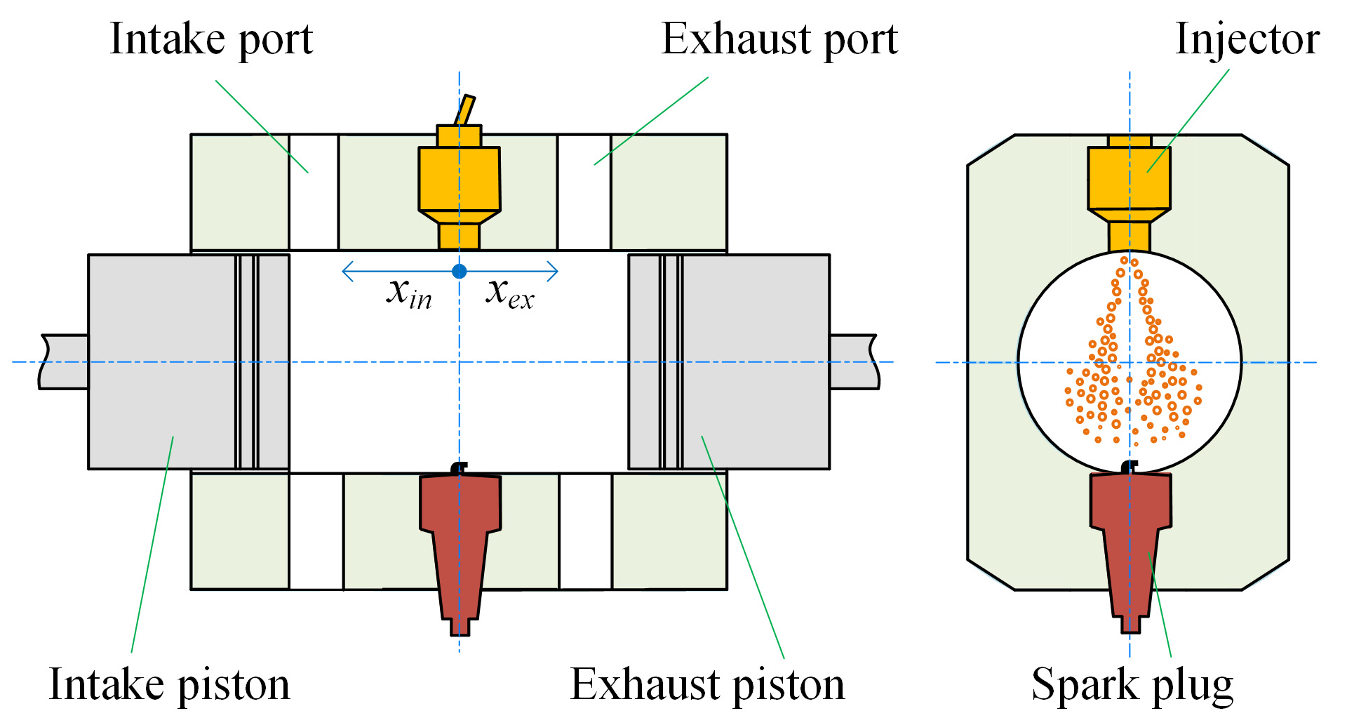
Figure 3.
Piston motion of the engine.
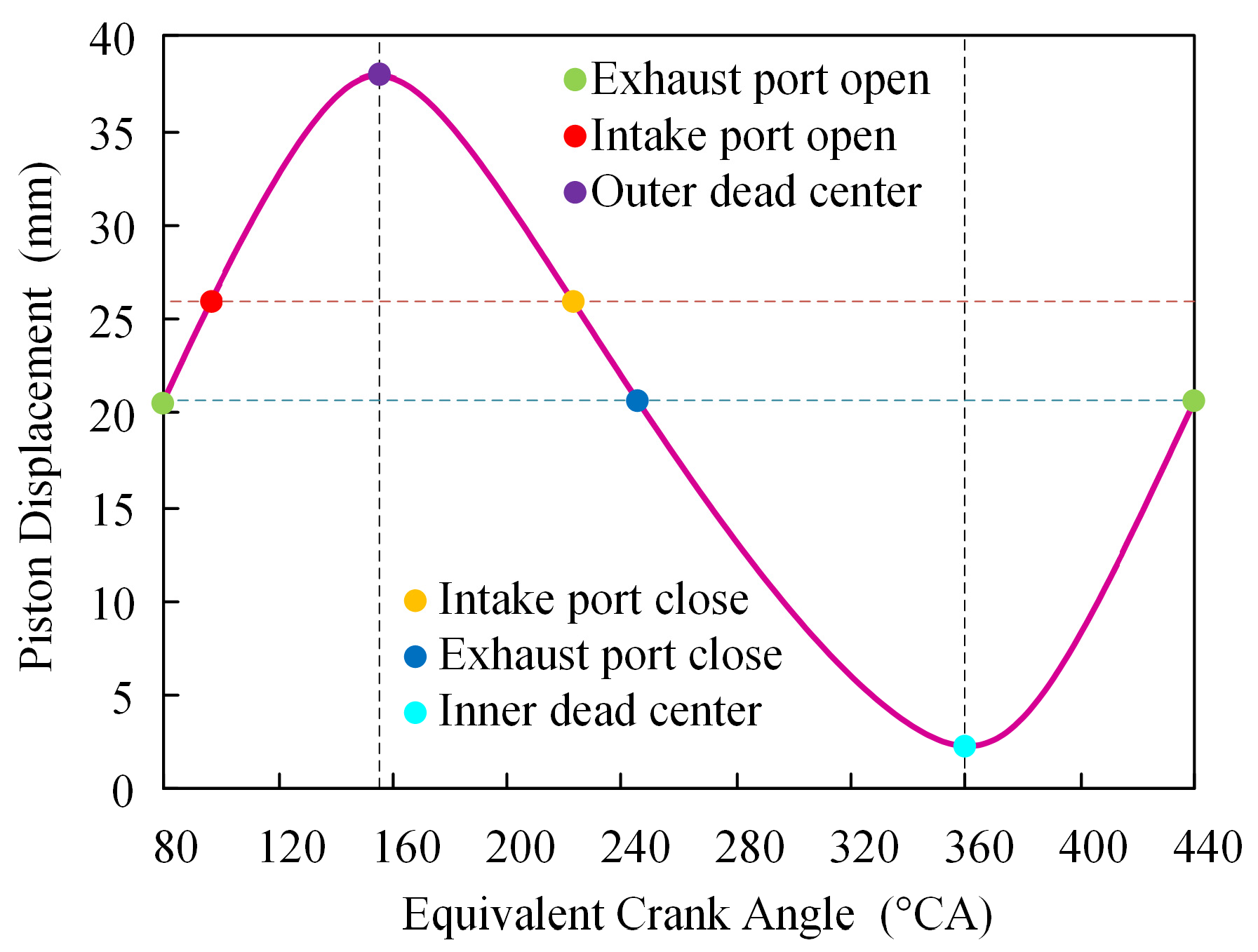
Figure 4.
Three-dimensional mesh model of the engine.

Figure 5.
In-cylinder fuel spray process.

Figure 6.
Comparison of tested and simulated spray morphology.4. Results and Discussions.
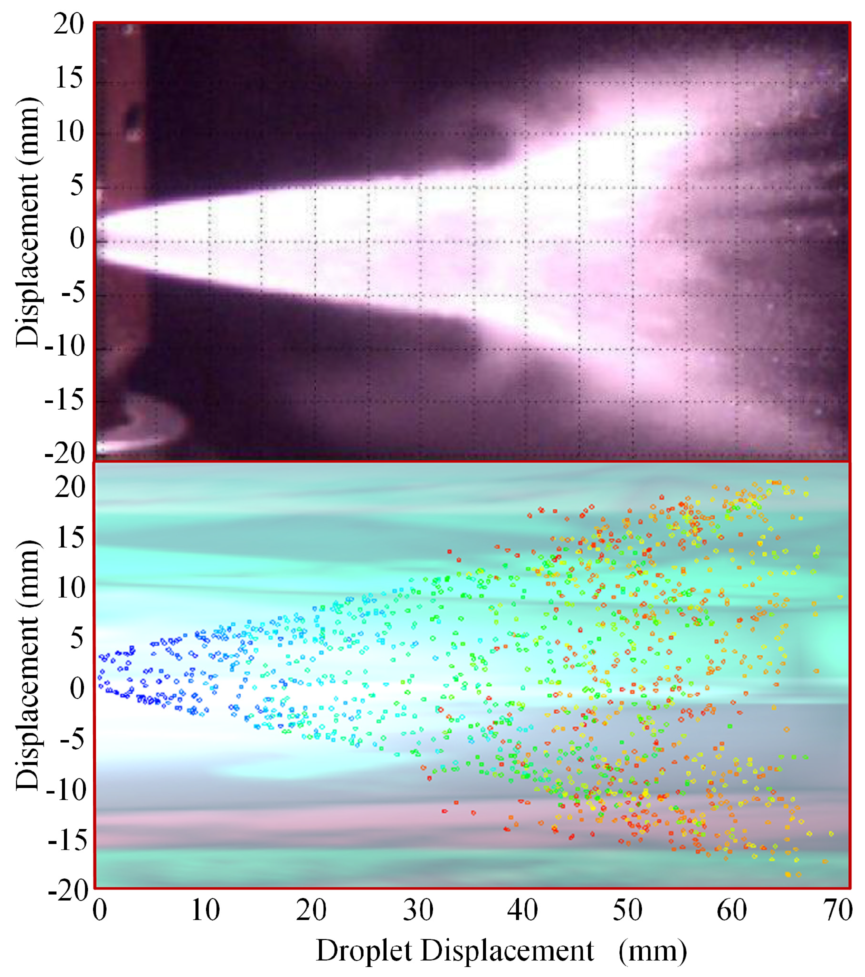
Figure 7.
Transient fuel evaporation rate of different spray angles.
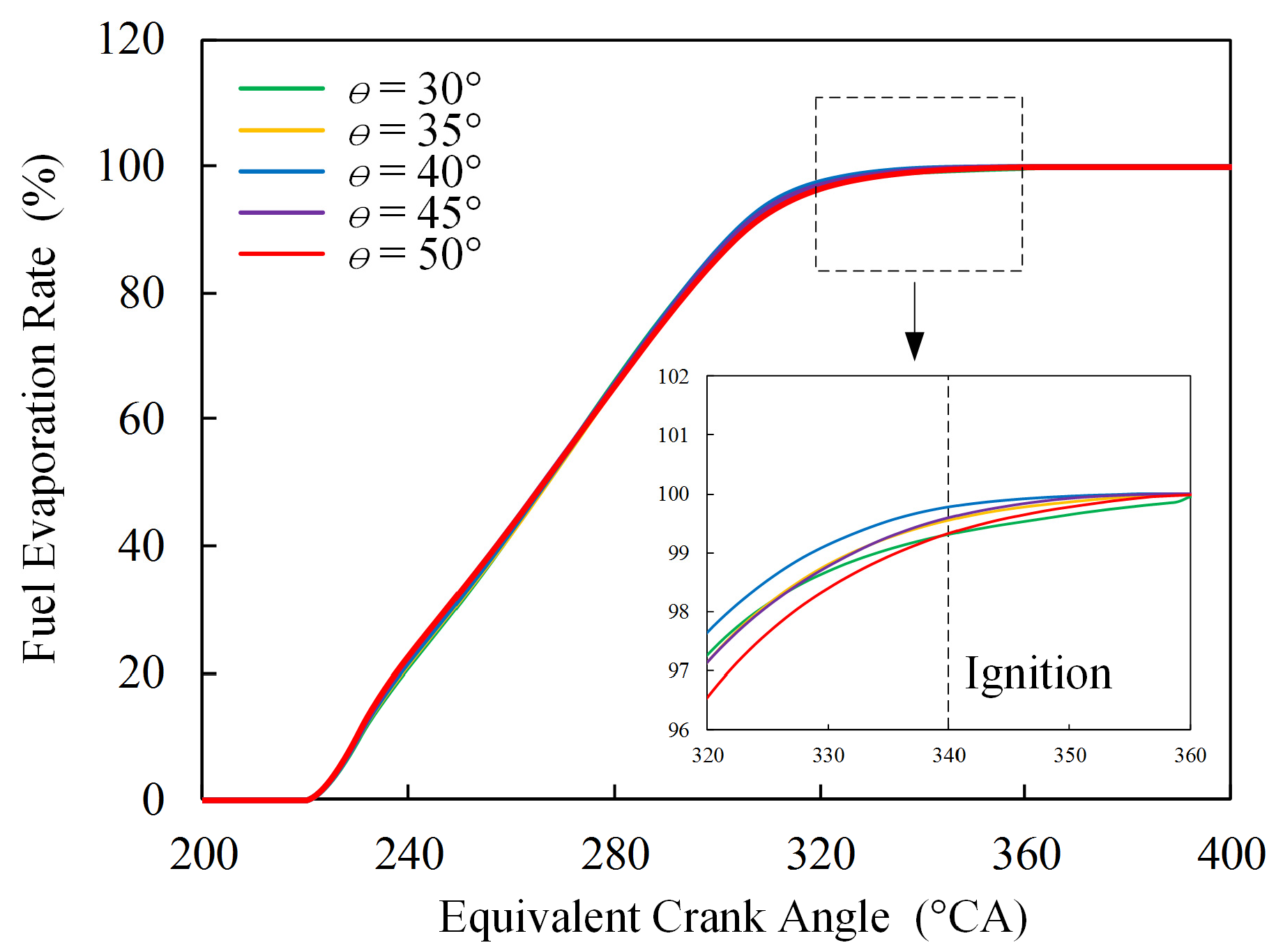
Figure 8.
Transient sauter mean diameter (SMD) of in-cylinder droplets of different spray angles.
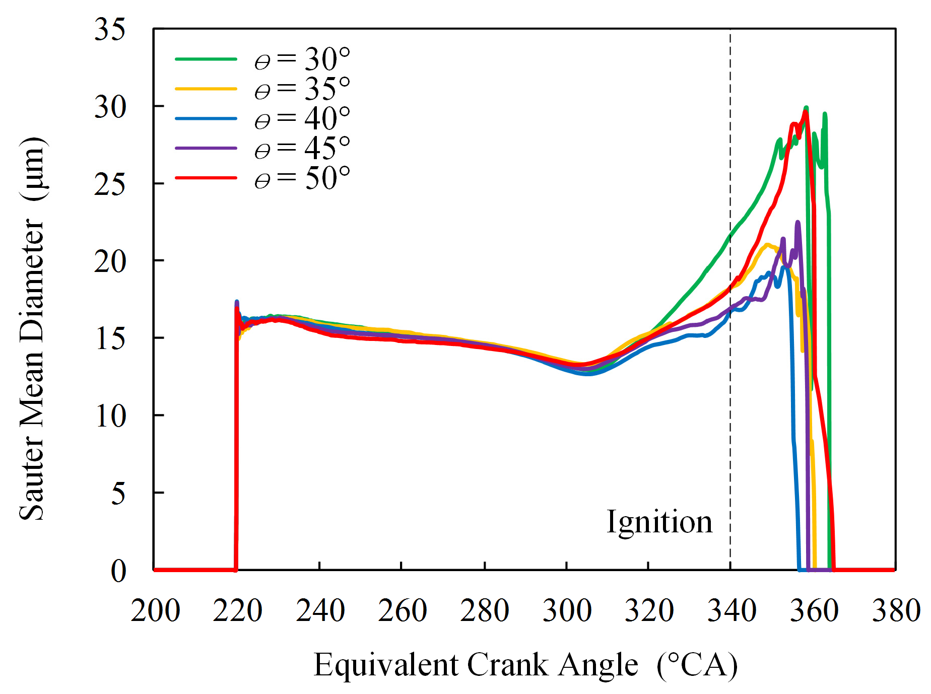
Figure 9.
Mixture distribution of different spray angles (340 °CA).

Figure 10.
Transient heat release rate of different spray angles.
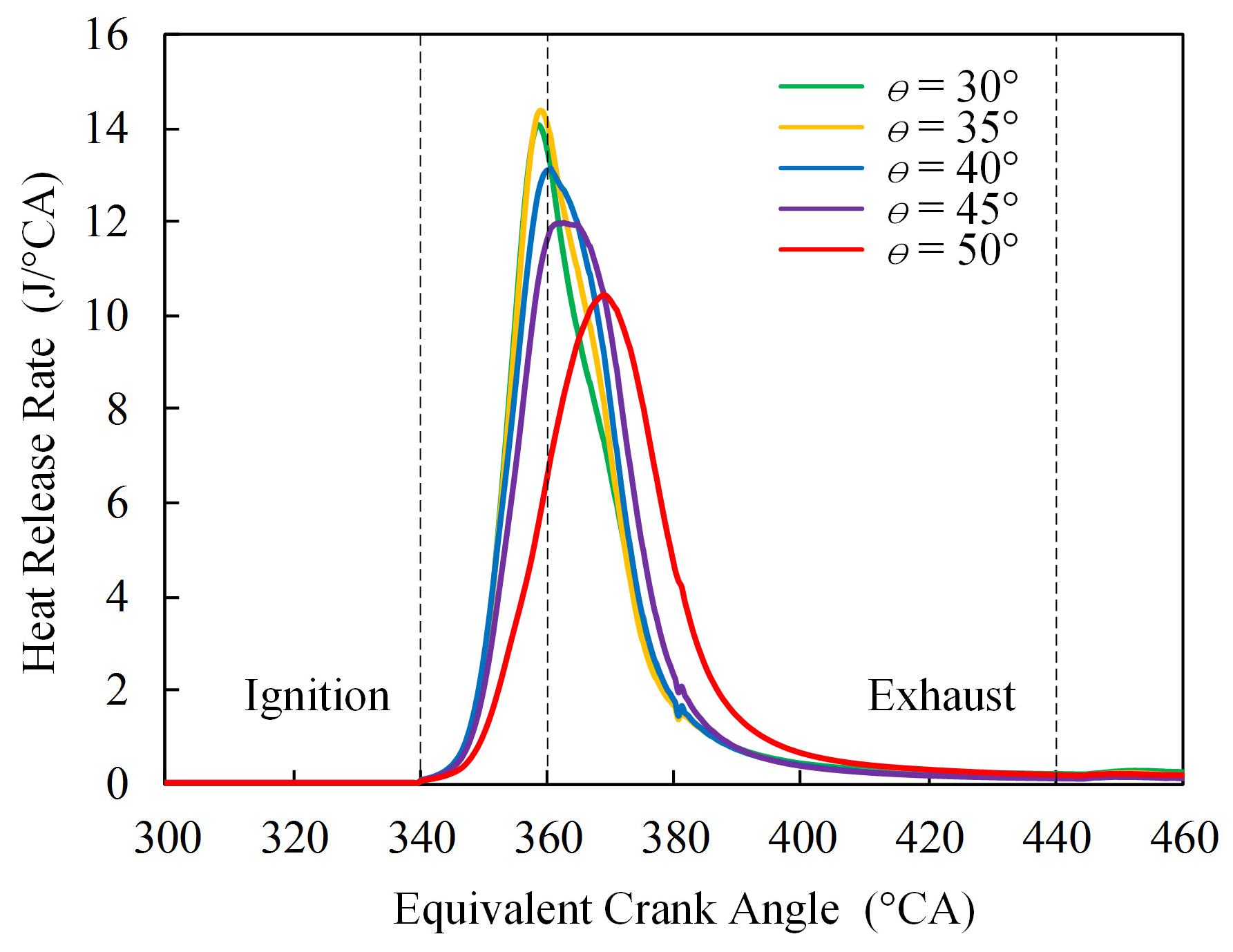
Figure 11.
Transient in-cylinder pressure of different spray angles.

Figure 12.
Unburnt fuel distribution of different spray angles (440 °CA).
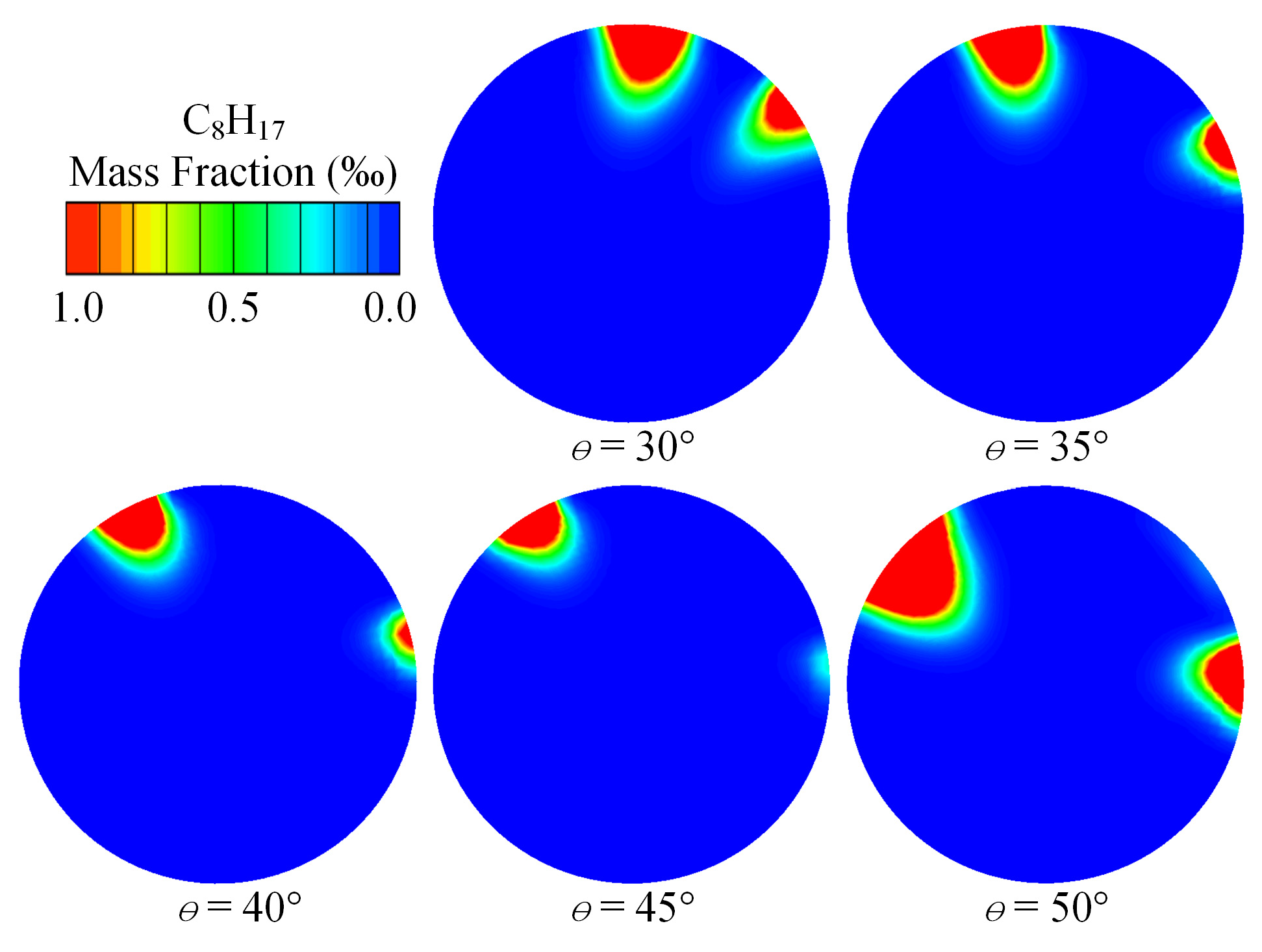
Figure 13.
Crank Angle 50 and Crank Angle 10–90 of different spray angles.

Figure 14.
Combustion efficiency and indicated thermal efficiency of different spray angles.
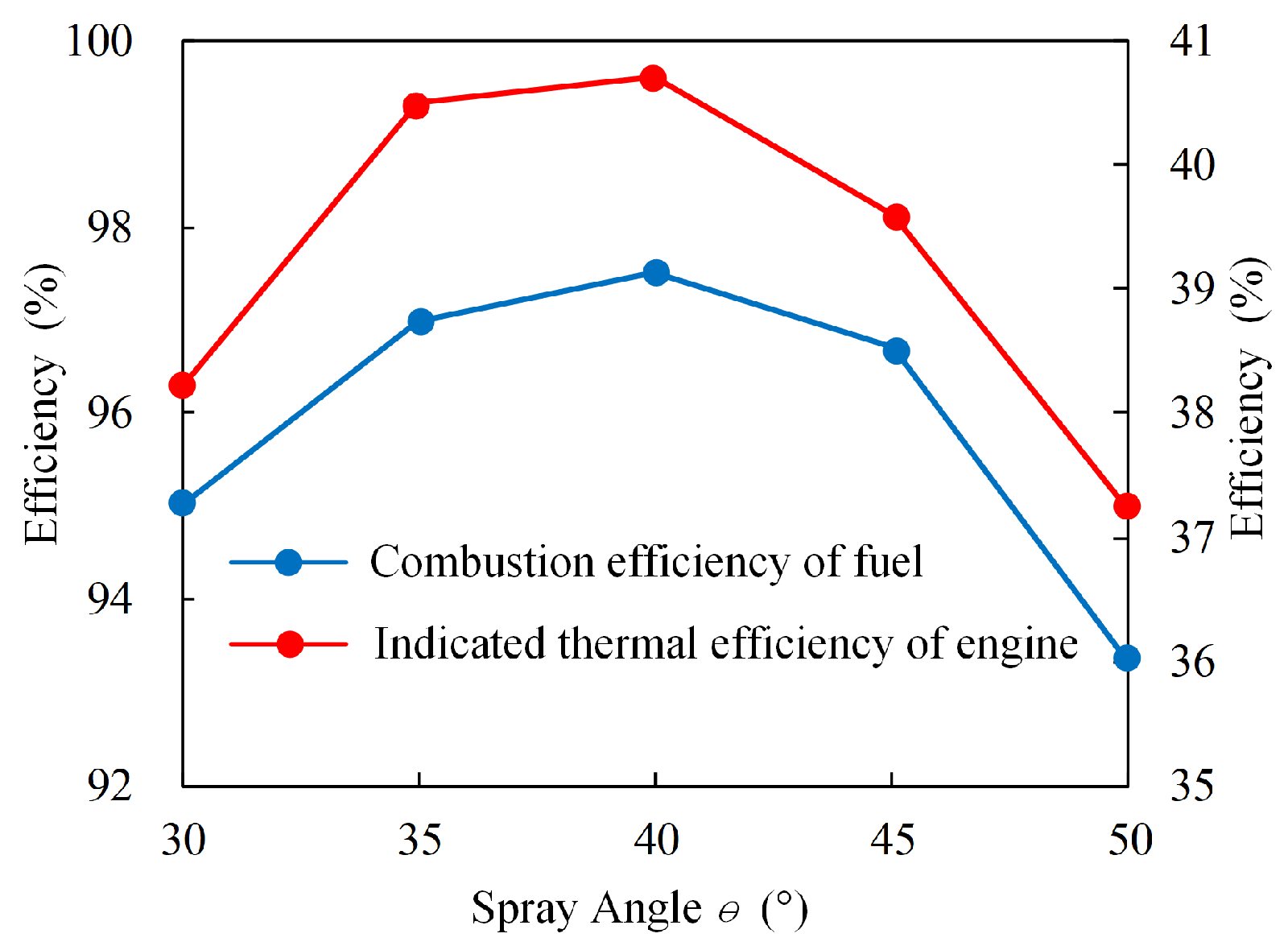
Figure 15.
CO distribution of different spray angles (440 °CA).

Figure 16.
CO mass fraction of different spray angles.
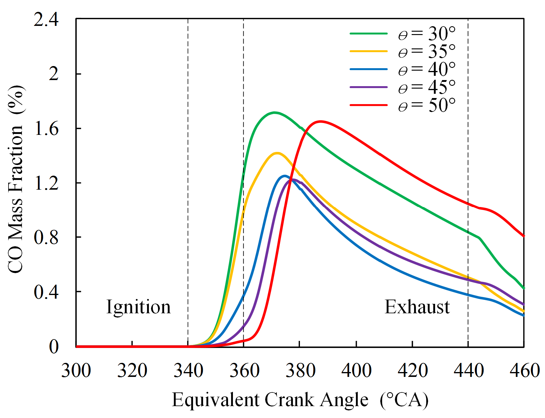
Figure 17.
Transient in-cylinder temperature of different spray angles.


Table 1.
Main parameters of the engine.
| Parameters | Content |
|---|---|
| Engine speed | 3500 r/min |
| Cylinder bore | 50 mm |
| Exhaust port position | 22 mm |
| Intake port position | 26 mm |
| Intake port width | 12 mm |
| Exhaust port width | 12 mm |
| Inner dead center (IDC) | 2.3 mm |
| Outer dead center (ODC) | 38 mm |
| Area of intake port | 562 mm2 |
| Area of exhaust port | 562 mm2 |
Table 2.
Main equivalent crank angle of the engine.
| Parameters | ECA (°CA) |
|---|---|
| Exhaust port open | 80 |
| Intake port open | 95 |
| Outer dead center | 154 |
| Intake port close | 223 |
| Exhaust port close | 241 |
| Inner dead center | 360 |
Table 3.
The initial conditions and boundary conditions.
| Parameters | Content |
|---|---|
| Intake pressure | 1.3 bar |
| Intake temperature | 320 K |
| Exhaust pressure | 1.1 bar |
| Exhaust temperature | 700 K |
| Cylinder pressure | 5.7 bar |
| Cylinder temperature | 1680 K |
| Exhaust gas recycle (EGR) | 1 |
Table 4.
Sub-models of spray process.
| Sub-Models | Content |
|---|---|
| Breakup | Taylor analogy breakup (TAB) |
| Evaporation | Dukowicz |
| Wall interaction | Walljet1 |
| Particle interaction | Schmidt |
Table 5.
Main parameters of combustion process.
| Parameters | Content |
|---|---|
| Flame model | Coherent flame/Extended coherent flame model (ECFM) |
| Stretch factor | 1.6 |
| Initial flame surface density | 630 |
Table 6.
Validated parameters of spray process.
| Parameters | Content |
|---|---|
| Injection fuel | Gasoline |
| Injection time | 220 °CA |
| Injection mass | 6.4 mg |
| Injection flow | 12.5 mg/ms |
| Ambient pressure | 1.5 bar |
| Ambient temperature | 293 K |
| Start velocity | 90 m/s |
| Particle sizes | 20 um |
Table 7.
Performance of the engine.
| Spray Angle (°) | CA10 (°CA Before Inner Dead Center) | CA50 (°CA After Inner Dead Center) | CA90 (°CA After Inner Dead Center) | Combustion Efficiency (%) | Indicated Efficiency (%) |
|---|---|---|---|---|---|
| 30 | 6.2 | 2.4 | 23.0 | 95.0 | 38.2 |
| 35 | 6.0 | 2.4 | 20.5 | 97.0 | 39.3 |
| 40 | 6.2 | 3.2 | 19.2 | 97.5 | 39.7 |
| 45 | 5.2 | 4.8 | 19.8 | 96.7 | 39.6 |
| 50 | 2.2 | 9.8 | 30.0 | 93.3 | 37.2 |
© 2020 by the authors. Licensee MDPI, Basel, Switzerland. This article is an open access article distributed under the terms and conditions of the Creative Commons Attribution (CC BY) license (http://creativecommons.org/licenses/by/4.0/).
Share and Cite
MDPI and ACS Style
Zhang, Q.; Xu, Z.; Liu, S.; Liu, L. Effects of Injector Spray Angle on Performance of an Opposed-Piston Free-Piston Engine. Energies 2020, 13, 3735. https://doi.org/10.3390/en13143735
AMA Style
Zhang Q, Xu Z, Liu S, Liu L. Effects of Injector Spray Angle on Performance of an Opposed-Piston Free-Piston Engine. Energies. 2020; 13(14):3735. https://doi.org/10.3390/en13143735
Chicago/Turabian StyleZhang, Qinglin, Zhaoping Xu, Shuangshuang Liu, and Liang Liu. 2020. "Effects of Injector Spray Angle on Performance of an Opposed-Piston Free-Piston Engine" Energies 13, no. 14: 3735. https://doi.org/10.3390/en13143735
Note that from the first issue of 2016, this journal uses article numbers instead of page numbers. See further details here.