Constant Output-Voltage Design for Bi-Directional Wireless Power Transfer System with Multiple Stages


College of Automation, Chongqing University, Chongqing 400044, China
*
Author to whom correspondence should be addressed.
Energies 2020, 13(14), 3739; https://doi.org/10.3390/en13143739
Submission received: 12 June 2020
/
Revised: 13 July 2020
/
Accepted: 13 July 2020
/
Published: 20 July 2020
(This article belongs to the Section A1: Smart Grids and Microgrids)
Abstract
:For the application of wireless power transfer (WPT) technology in a robot (like the snake robot), the power is supposed to be transferred to each device across multiple robot joints. This paper proposes a multi-stage bi-directional WPT (MB-WPT) system that not only provides power to multiple loads but also increases the power transfer distance. Besides, the last stage can charge for the preceding stages by reverse power transfer. The constant output voltage can be achieved whether the power is transmitted in a forward or reverse direction, and different output voltages for each stage can be achieved to satisfy the respective voltage requirement through the parameter design method. The validity of the theoretical analysis and the feasibility of the system are verified by experiments.
1. Introduction
Based on the principle of magnetic induction, wireless power transfer (WPT) technology realizes non-contact transmission of energy from the transmitter to the receiver. Currently, WPT technology is widely used in electric vehicles, kitchen appliances, household equipment, mining equipment, implantable medical devices, and so on. WPT technology simplifies the structure of power transfer system, improves its performance, and makes the appliances more compact [1,2,3,4]. For robot applications, the flexibility and convenience of power supply can be improved by using wireless power transfer technology. As for the snake robot application, it is necessary to provide power for multiple loads. If the power can be transferred through robot joints to multiple loads, the risks of corrosion, twisting or damage due to insulation can be reduced. The flexibility and robustness of robot joint rotation can be improved. Furthermore, if the last stage can charge for the preceding stages which have power shortage, it can extend the working time of the snake robot. Therefore, the multi-stage bi-directional power transmission can improve the performance of the snake robot.
In a WPT system, both the magnetic field and efficiency decrease rapidly with increased distance [5,6]. Through adding repeaters between the transmitter and the receiver, the transmission distance increases significantly, the transmission power and efficiency are enhanced, and the system performance is improved [7,8,9]. A battery-charging system with one repeater is proposed to expand the charging area [10]. To improve the efficiency of the system, the distance between the coils and the operation frequency are optimized [11]. The frequency splitting caused by a medium frequency and an odd number of repeaters in the system is also analyzed [12]. It also evaluates the output power and efficiency of the system by optimizing the position and number of the repeaters. A new relay coil is proposed to increase the position flexibility. The previous studies indicate that the frequency of a domino WPT system is relatively high. To reduce the power loss of the coils, a domino WPT system with a relatively low operation frequency is designed [13]. It is demonstrated that the coaxial straight domino system with unequal spacing has a higher efficiency than the system with equal spacing. Through the analysis of non-coaxial domino WPT systems, an optimization of the domino system is proposed with more than one power flow path [14]. The method in [15] proposes the design using a two-, three-, or four-coil link to be appropriate for particular applications and to reach optimal coil geometries. Compared with the 4-coil counterpart, the 3-coil WPT link has advantages in power transfer efficiency and power delivered to the load at large coupling distances [16]. A triple-loop WPT system proposed in [17] keeps the power transfer efficiency at its peak by simultaneously operating three loops and maintaining the robustness and stability. A multiple-transmitter WPT system proposed in [18] can improve power transfer efficiency, whether it is angular aligned or angular misaligned, of the coils over all regions. The above studies investigate WPT systems with repeaters. However, the repeater coil added to the above systems only increases transmission distance and improves output power and efficiency, but does not transmit energy to multiple loads.
Concerning the bi-directional WPT system, a matrix converter is proposed in [19,20]. By using this converter, the DC-link capacitor and input inductance are removed, the unnecessary harmonics in the grid current are reduced, and the switching strategy is simplified. A bi-directional current-fed parallel resonant push-pull inverter is proposed in [21] to improve the efficiency and output voltage of the system. Some control strategies for bi-directional WPT systems are proposed in [22,23], which control the amount and direction of power by regulating the phase and amplitude of the converters on both the primary and secondary sides. The phase-shifting modulation strategy for a bi-directional WPT system is optimized, and the coil loss of the Series-Series (SS) topology is reduced [24]. A power-frequency control method for a bi-directional WPT system that controls the amount and direction of power flow is presented [25]. Three control modes for power flow control of electric vehicles are proposed [26]: charge, discharge, and abstain (no interaction). Based on the genetic algorithm determining the parameters of the Proportion-Integral-Differential (PID) controller, a PID control strategy for bi-directional WPT system is proposed [27]. A mathematical model of a bi-directional WPT system is established to achieve the optimal performance of the system according to the following aspects [28,29,30]. The system controller is designed, the behavior of a bi-directional WPT system is predicted, and the active and reactive power under V2G mode and G2V mode are accurately estimated. A bi-directional WPT system is proposed [31], in which the resonant frequency is regulated by an integral control method to ensure the fast and stable operation of the system. The above papers mainly study the bi-directional power transmission between the power grid and the electric vehicle. However, these methods could not be utilized in the snake robot system because the demand of multiple-load output along the power transmission chain is not taken into account.
A WPT system with repeaters for multiple loads is proposed in [32]. Every two bipolar coils form a repeater unit where one receives power from its preceding unit and the other transmits power to the subsequent unit. Multiple loads are powered by repeaters through connecting each load to a repeater unit. The system proposed in [32] ensures constant load currents regardless of load variation. However, the system cannot satisfy the requirement of bi-directional power transmission because if the power is transferred reversely, the system cannot ensure load-independent characteristics.
This paper proposes a wireless power transfer system for snake robot application with multiple loads and long power transfer distances. When the robot leaves the power source and the preceding stages involve power shortage, the last stage can charge for the preceding stages by reverse power transfer. The constant output voltage can be realized in both power transfer directions. Furthermore, different output voltages of each stage can be achieved to satisfy the respective voltage requirement.
In this paper, firstly, a three-stage multi-stage bi-directional WPT (MB-WPT) system is taken as an example to analyze the proposed method, and the equivalent circuit model is established based on the system. Secondly, the output characteristic of the system is analyzed in two modes. Thirdly, the different output voltage of each stage is achieved by parameter design of topology. Finally, the experimental results have validated the effectiveness of the proposed WPT system.
2. Proposed MB-WPT System
A three-stage system is taken as an example to analyze the proposed MB-WPT system, and the schematic diagram is shown in Figure 1. Aiming at the application of moving equipment like the robot, normally, a static power input stage (Stage 1) which is connected to the DC power supply is required to charge a robot battery. The remaining stages (Stage 2 and Stage 3) are mounted on the robot. In this paper, the power transfer among multiple stages on the robot should be bi-directional to distribute energy among multiple devices on the robot. In the forward power transmission, the power is transferred from power gird (Stage 1) to moving equipment which includes Stage 2 and Stage 3. The DC voltage of the power source is expressed as Udc1. A high-frequency full-bridge inverter working at a fixed frequency is utilized to produce a square-wave voltage source for the following resonant tanks. The operation frequency is f, and the angular frequency is ω (ω = 2πf). In the MB-WPT system, the battery is used as the load at each stage. If the robot leaves the power source and the preceding stages have power shortage, the system works in Mode B, where the power is transferred from Stage 3 to Stage 2. It is not necessary to transfer power from the moving equipment to the power gird. Therefore, the charging process (forward power transfer process) covers Stage 1, Stage 2 and Stage 3, while the reverse power transfer process only covers Stage 2 and Stage 3. In Mode B, the battery of the last stage charges for the preceding stages by reverse power transmission and the voltage of the battery is expressed as Udc3. To analyze the system, some fundamental definitions are proposed as follows: the resistances of each primary coil and each secondary coil are expressed as Rpi and Rsi, and the mutual inductance is expressed as Mi. There are three stages in the system which can be divided into three categories. LCCL topology (Lp11-Cp11-Cp12-Lp12) is adopted in Stage 1, LC series topology (Ls2-Cs2) is adopted in Stage 3, and Stage 2 adopts both topologies (Lp21-Cp21-Cp22-Lp22 and Ls1-Cs1). Each joint consists of a primary coil of the preceding stage and a secondary coil of the subsequent stage. The impedances of the loads are expressed as R2 and R3, and the equivalent AC impedances of the loads are expressed as Rl2 and Rl3. The relation between Rli and Ri is Rli = 8Ri/π2 (i = 2, 3).
The relationship between the AC voltage Uaci after inversion and the DC voltage Udci is as follows:
If Equation (2) is satisfied, the equivalent impedances of all resonant networks exhibit resistance.
3. Two Operation Modes for MB-WPT System
3.1. Mode A
3.2. Mode B
4. Output Characteristic Analysis
In the multi-stage WPT system, it is necessary to guarantee that each stage has a steady output performance. The load and the mutual inductance may vary in the application of a WPT system. The output characteristics of the system are analyzed from the variation of loads and mutual inductances, and the calculated results and analysis are as follows.
4.1. Analysis of the Output Voltage
In Mode A, because the resistances of coils are smaller than the loads, assuming that the resistances of the coils are ignored, the output voltage at each stage is
Equations (7) and (8) indicate that the output voltages are independent of the loads. Similarly, in Mode B, the output voltage Ubo2 can be simplified if the resistance of each coil is negligible, and it is expressed as
According to Equation (9), when the system works in Mode B, the output voltage is independent of the load.
The calculated results and analysis under both power transfer directions are as follows.
Figure 4 shows the relationship between the output voltages and the loads when the system works in Mode A. As can be seen from Figure 4, when the load resistances R2 and R3 both increase from 10 to 30 Ω, Uao2 varies from 29.5 to 31.7 V and Uao3 varies from 25.7 to 28.7 V, and in other words, both output voltages vary slightly. It can be understood that the output voltage at each stage is independent of the loads under the condition of Mode A.
The relationship between the output voltages and the mutual inductances in Mode A is shown in Figure 5. In the design of a robot MB-WPT system, the relative position of the primary coil and secondary coil at each stage varies little, so that the variation of mutual inductance is also small. As can be seen from Figure 5a, Uao2 varies slightly with the increase in M2, but it is determined by M1. When M1 and M2 increase from 6 to 7 μH, Uao2 increases from 25 to 29.8 V. Figure 5b shows the variation of Uao3 with the mutual inductances. When both M1 and M2 increase from 6 to 7 μH, the minimum of Uao3 is 20 V, and the maximum of Uao3 is 26.9 V.
Figure 6 shows the variation of the output voltage with the mutual inductance and the load in Mode B. It can be seen that Ubo2 is independent of the load, but it decreases with the increase in M2. When M2 increases from 6 to 7 μH, Ubo2 decreases from 35 to 29 V.
4.2. Analysis of the Efficiency
In the WPT system, the efficiency is worthy of attention. The calculated results and analysis of the variation of the efficiency with the mutual inductances and the loads are as follows.
The variation of the efficiency η with the mutual inductances and the loads in Mode A are shown in Figure 7. Figure 7a shows the variation of η with the increase in the loads. η increases with the increase in R2 and R3. When the loads R2 and R3 increase from 10 to 30 Ω, the efficiency η increases from 87% to 94.5%. Figure 7b shows the variation of η with the increase in the mutual inductances. It can be observed that η varies slightly with the increase in M1, but it decreases with the increase in M2. When the mutual inductances M1 and M2 increase from 6 to 7 μH, the efficiency η decreases from 83.7% to 82%.
Figure 8 shows the variation of the efficiency η with the mutual inductance and the load when the system works in Mode B. It can be seen from Figure 8 that η increases with the increase in R2 and M2. In the calculation model, when R2 increases from 10 to 30 Ω, M2 increases from 6 to 7 μH, and the efficiency η increases from 91.5% to 97.2%.
4.3. Loss Analysis of Each Stage
The loss of the system is mainly caused by the resistance of the coils. The loss of each stage is analyzed under the variation of the loads and the mutual inductances. The calculated results are as follows.
The variation of the loss PLoss with the loads and the mutual inductances in Mode A is shown in Figure 9. According to the characteristic of the LCCL topology, the current in the Lp12 of Stage 1 is constant. Therefore, the loss in Stage 1 is constant with the variation of the loads and the mutual inductances. Figure 9a shows the variation of PLoss with the increase in the loads. When the loads R2 and R3 increase from 10 to 30 Ω, the loss in Stage 1 is 1.7 W, the loss in Stage 2 decreases from 23 to 3.7 W, and the loss in Stage 3 decreases from 6 to 0.9 W. Figure 9b shows the variation of PLoss with the increase in the mutual inductances. When M1 and M2 increase from 6 to 7 μH, the loss in Stage 1 is 1.7 W, the loss in Stage 2 increases from 13 to 23.2 W, and the loss in Stage 3 increases from 3.1 to 5.6 W.
Figure 10 shows the variation of the loss PLoss with the load and the mutual inductance when the system works in Mode B. It can be seen from Figure 10a that the loss in Stage 2 increases with the increase in R2, and it decreases with the increase in M2. Figure 10b illustrates that the loss in Stage 3 decreases with the increase in R2 and M2. When R2 increases from 10 to 30 Ω, M2 increases from 6 to 7 μH, the loss in Stage 2 varies from 2.1 to 3.1 W, and the loss in Stage 3 varies from 12.5 to 0.5 W.
5. Parameter Design Method
When the power is transmitted in the forward and reverse directions, it is necessary to maintain the output voltage constant. Most importantly, the output voltage at each stage should satisfy the respective voltage requirement.
From Equations (7)–(9), it is seen that the output voltages are insensitive to the variation of the loads, but they can be determined by Lpi and Mi (i = 1, 2). If the output voltage ratio of Stage i and Stage i + 1 is λi, then Lpi can be designed as Lpi = λiMi (i = 1, 2), and Cpi1 and Cpi2 can be set as follows:
The parameter design flowchart of topology is shown as follows.
The design steps of the topology parameter are illustrated in Figure 11. Through the above parameter design method, the different output voltage of each stage can be achieved to satisfy the respective voltage requirement.
6. Experimental Verification
To verify the proposed method, an experimental demonstration platform that was used for charging the snake robot is shown in Figure 12. There were two operation modes in the MB-WPT system, Mode A and Mode B. The LCCL-LC-LCCL-LC topology structure was adopted in the system. The primary and secondary coils were designed as a cylindrical structure with the diameters of 50 mm and 45 mm, respectively, and their height is 50 mm. The experimental parameters are listed in Table 3.
6.1. Mode A
When the power is transferred in the forward direction, the variations of output voltages and input current with the loads are shown in Figure 13. Uao2 and Uao3 are the output voltages of Stage 2 and Stage 3, respectively, ILp11 is the current in the Lp11, and it is also the input current of the system. When R3 = 30 Ω, and R2 varies from 30 to 10 Ω, Uao2 varies from 31.2 to 28.1 V, Uao3 varies from 27.1 to 25 V, and ILp11 varies from 2.16 to 3.87 A. ΔUao2 = 3.1V, ΔUao3 = 2.1 V. It can be concluded that output voltages vary little with the variations of loads. With the decrease in the R2, the output power increases, and the input power increases. Therefore, the input current ILp11 increases. Similar to Figure 13a, when R3 = 10 Ω, and R2 varies from 30 to 10 Ω, Uao2 varies from 28.6 to 27.9 V, Uao3 varies from 24.6 to 23.9 V, and ILp11 varies from 3.19 to 4.68 A. ΔUao2 = 0.7 V, ΔUao3 = 0.7 V. When R2 = 30 Ω, and R3 varies from 30 to 10 Ω, Uao2 varies from 31.2 to 28.6 V, Uao3 varies from 27.1 to 24.6 V, and ILp11 varies from 2.16 to 3.19 A. ΔUao2 = 2.6 V, ΔUao3 = 2.5 V. When R2 = 10 Ω, and R3 varies from 30 to 10 Ω, Uao2 varies from 28.1 to 27.9 V, Uao3 varies from 25 to 23.9 V, and ILp11 varies from 3.87 to 4.68 A. ΔUao2 = 0.2 V, ΔUao3 = 1.1 V. From the above experimental results, it can be seen that the output voltages are insensitive to the variation of the loads. The experimental results are consistent with the theoretical analysis.
When the power is transferred forward, the variation of output voltages and input current with the rotation of secondary coils, and the rotation schematic of the secondary coils are shown in Figure 14. The rotation angle of the secondary coil is marked as θi. When both secondary coils rotate from 0° to 360°, the fluctuation of the output voltages is very small. That is because the variation of the mutual inductances with the rotation of the secondary coil is very small.
6.2. Mode B
When the power is transferred in the reverse direction, the variations of output voltage and input current with the load are shown in Figure 15. Ubo2 is the output voltage of Stage 2, Ics2 is the current in the Cs2, and it is also the input current of the system. When R2 varies from 30 to 10 Ω, Ubo2 varies from 34.9 to 32.8 V, and Ics2 varies from 1.19 to 3.6 A. ΔUbo2 = 2.1 V. It can be concluded that the output voltage varies little with the variations of the load when the power is transferred reversely. The experimental results are consistent with the theoretical analysis.
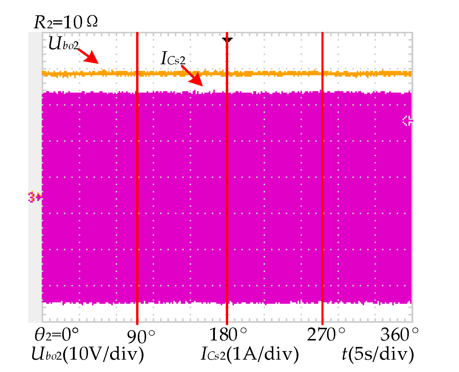
When the power is transferred reversely, the variation of output voltage and input current with the rotation of the secondary coil are shown in Figure 16. Similar to forward power transmission, when the secondary coil rotates from 0° to 360°, the fluctuation of the output voltage is very small.
The output power and the efficiency are listed in Table 4.
7. Conclusions
The MB-WPT system proposed in this paper is mainly applied on the snake robot with a long power transfer distance. Besides, the system can satisfy the requirements of multiple loads and bi-directional power transmission. A three-stage MB-WPT system is taken as an example to analyze the proposed method, and the equivalent circuit model of the system is established on this basis. Then, the output characteristic of the system is analyzed by calculation and simulation. In both operation modes, Mode A and Mode B, the constant output voltage can be achieved, and a different output voltage for each stage can be achieved to satisfy the respective voltage requirement. Finally, the experimental results have validated the effectiveness of the proposed WPT system.
Author Contributions
J.W. and X.D. proposed the main idea and conception. J.W. analyzed the data and designed the experiment. Z.W. contributed the topology design and experiment. All authors have read and agreed to the published version of the manuscript.
Funding
This research was funded by National Key R&D Program of China by MOST, grant number 2018YFB0106300.
Conflicts of Interest
The authors declare no conflict of interest.
Nomenclature
| Symbol | Description |
|---|---|
| Udci | Input voltage of Stage i |
| Uaci | Output voltage of inverter in Stage i |
| Ri | Load of Stage i |
| Si1, Si2, Si3, Si4 | Driving signal of the inverter in Stage i |
| Ci | Filter capacitor of Stage i |
| Lpi2, Lsi | Primary and secondary coils of Joint i |
| Lpi1, Cpi1, Cpi2, Csi-1 | Compensation inductance and capacitances of Stage i |
| Rpi, Rsi | Resistances of the primary and secondary coils in Joint i |
| f, w | Operation frequency and angle frequency |
| Uaoi, Uboi | Output voltage when the power is transferred in both directions |
| Pout_a, Pout_b | Output power when the power is transferred in both directions |
| Mi | Mutual inductance of Joint i |
| η | The efficiency of the system |
References
- Thrimawithana, D.-J.; Madawala, U.-K. A primary side controller for inductive power transfer systems. In Proceedings of the IEEE International Conference on Industrial Technology, Vina del mar, Chile, 14–17 March 2010; pp. 661–666. [Google Scholar]
- Kissin, M.-L.-G.; Huang, C.-Y.; Covic, G.-A. Detection of the Tuned Point of a Fixed-Frequency LCL Resonant Power Supply. IEEE Trans. Power Electron. 2009, 24, 1140–1143. [Google Scholar] [CrossRef]
- Wu, H.-H.; Gilchrist, A.; Sealy, K. A review on inductive charging for electric vehicles. In Proceedings of the Electric Machines & Drives Conference, Niagara Falls, ON, Canada, 15–18 May 2011; pp. 143–147. [Google Scholar]
- Wang, Z.-H.; Li, Y.-P.; Sun, Y. Load Detection Model of Voltage-Fed Inductive Power Transfer System. IEEE Trans. Power Electron. 2013, 28, 5233–5243. [Google Scholar] [CrossRef]
- Waffenschmidt, E.; Staring, T. Limitation of inductive power transfer for consumer applications. In Proceedings of the European Conference on Power Electronics and Applications, Barcelona, Spain, 8–10 September 2009; pp. 1–10. [Google Scholar]
- Mur-Miranda, J.-O.; Fanti, G.; Feng, Y. Wireless power transfer using weakly coupled magnetostatic resonators. In Proceedings of the Energy Conversion Congress and Exposition, Atlanta, GA, USA, 12–16 September 2010; pp. 4179–4186. [Google Scholar]
- Zhang, F.; Hackworth, S.-A.; Fu, W. Relay Effect of Wireless Power Transfer Using Strongly Coupled Magnetic Resonances. IEEE Trans. Magn. 2011, 47, 78–1481. [Google Scholar] [CrossRef]
- Luo, B.; Wu, S.; Zhou, N. Flexible Design Method for Multi-Repeater Wireless Power Transfer System Based on Coupled Resonator Bandpass Filter Model. IEEE Trans. Circuits Syst. I Regul. Pap. 2014, 61, 3288–3297. [Google Scholar] [CrossRef]
- Hui, S.-Y.-R.; Zhong, W.; Lee, C.-K. A Critical Review of Recent Progress in Mid-Range Wireless Power Transfer. IEEE Trans. Power Electron. 2014, 29, 4500–4511. [Google Scholar] [CrossRef] [Green Version]
- Phaebua, K.; Lertwiriyaprapa, T.; Chalermwisutkul, S. Area extension of a wireless battery charging system using multiple power repeater coil antennas. In Proceedings of the International Conference on Intelligent Green Building and Smart Grid, Prague, Czech Republic, 27–29 June 2016; pp. 1–4. [Google Scholar]
- Chi, K.-L.; Zhong, W.-X.; Hui, S.-Y.-R. Effects of Magnetic Coupling of Nonadjacent Resonators on Wireless Power Domino-Resonator Systems. IEEE Trans. Power Electron. 2012, 27, 1905–1916. [Google Scholar]
- Ahn, D.; Hong, S. A Study on Magnetic Field Repeater in Wireless Power Transfer. IEEE Trans. Ind. Electron. 2013, 60, 360–371. [Google Scholar] [CrossRef]
- Zhong, W.-X.; Chi, K.-L.; Hui, S.-Y. Wireless Power Domino-Resonator Systems With Noncoaxial Axes and Circular Structures. IEEE Trans. Power Electron. 2012, 27, 4750–4762. [Google Scholar] [CrossRef] [Green Version]
- Lower, T.-E.; Fragar, L.; Depcynzksi, J. General Analysis on the Use of Tesla’s Resonators in Domino Forms for Wireless Power Transfer. IEEE Trans. Ind. Electron. 2013, 60, 261–270. [Google Scholar]
- Mehdi, K.; Maysam, G. A Figure-of-Merit for Designing High-Performance Inductive Power Transmission Links. IEEE Trans. Power Electron. 2013, 60, 5292–5305. [Google Scholar]
- Mehdi, K.; Uei-Ming, J.; Maysam, G. Design and Optimization of a 3-Coil Inductive Link for Efficient Wireless Power Transmission. IEEE Trans. Biomed. Circuits Syst. 2011, 5, 579–591. [Google Scholar]
- Byunghun, L.; Mehdi, K.; Maysam, G. A Triple-Loop Inductive Power Transmission System for Biomedical Applications. IEEE Trans. Biomed. Circuits Syst. 2016, 10, 138–148. [Google Scholar]
- Kisong, L.; Dong-Ho, C. Diversity Analysis of Multiple Transmitters in Wireless Power Transfer System. IEEE Trans. Magn. 2013, 49, 2946–2952. [Google Scholar]
- Weearsinghe, S.; Thrimawithana, D.-J.; Madawala, U.-K. Modeling Bidirectional Contactless Grid Interfaces With a Soft DC-Link. IEEE Trans. Power Electron. 2015, 30, 3528–3541. [Google Scholar] [CrossRef]
- Weerasinghe, S.; Madawala, U.-K.; Thrimawithana, D.-J. A Matrix Converter-Based Bidirectional Contactless Grid Interface. IEEE Trans. Power Electron. 2017, 32, 1755–1766. [Google Scholar] [CrossRef]
- Namadmalan, A. Bidirectional Current-Fed Resonant Inverter for Contactless Energy Transfer Systems. IEEE Trans. Ind. Electron. 2015, 62, 238–245. [Google Scholar] [CrossRef]
- Madawala, U.-K.; Thrimawithana, D.-J. A Bidirectional Inductive Power Interface for Electric Vehicles in V2G Systems. IEEE Trans. Ind. Electron. 2011, 58, 4789–4796. [Google Scholar] [CrossRef]
- Madawala, U.-K.; Thrimawithana, D.-J. Current sourced bi-directional inductive power transfer system. Power Electron. Iet 2011, 4, 471–480. [Google Scholar] [CrossRef]
- Nguyen, B.-X.; Vilathgamuwa, D.-M.; Foo, G.-H.-B. An Efficiency Optimization Scheme for Bidirectional Inductive Power Transfer Systems. IEEE Trans. Power Electron. 2015, 30, 6310–6319. [Google Scholar] [CrossRef]
- Madawala, U.-K.; Neath, M.; Thrimawithana, D.-J. A Power–Frequency Controller for Bidirectional Inductive Power Transfer Systems. IEEE Trans. Ind. Electron. 2013, 60, 310–317. [Google Scholar] [CrossRef]
- Mohamed, A.-A.-S.; Berzoy, A.; Mohammed, O. Predictive active power-flow control of two-way wireless power transfer system in V2G services. In Proceedings of the Power Electronics Conference, Auckland, New Zealand, 5–8 December 2016; pp. 1–6. [Google Scholar]
- Neath, M.-J.; Swain, A.-K.; Madawala, U.-K. An Optimal PID Controller for a Bidirectional Inductive Power Transfer System Using Multiobjective Genetic Algorithm. IEEE Trans. Power Electron. 2013, 29, 1523–1531. [Google Scholar] [CrossRef]
- Swain, A.-K.; Neath, M.-J.; Madawala, U.-K. A Dynamic Multivariable State-Space Model for Bidirectional Inductive Power Transfer Systems. IEEE Trans. Power Electron. 2012, 27, 4772–4780. [Google Scholar] [CrossRef]
- Thrimawithana, D.-J.; Madawala, U.-K. A Generalized Steady-State Model for Bidirectional IPT Systems. IEEE Trans. Power Electron. 2013, 28, 4681–4689. [Google Scholar] [CrossRef]
- Mohamed, A.-A.-S.; Berzoy, A.; Mohammed, O.-A. Experimental Validation of Comprehensive Steady-State Analytical Model of Bidirectional WPT System in EVs Applications. IEEE Trans. Veh. Technol. 2017, 66, 5584–5594. [Google Scholar] [CrossRef]
- Miskiewicz, R.-M.; Moradewicz, A.-J.; Kazmierkowski, M.-P. Contactless battery charger with bi-directional energy transfer for plug-in vehicles with vehicle-to-grid capability. In Proceedings of the IEEE International Symposium on Industrial Electronics, Gdansk, Poland, 27–30 June 2011; pp. 1969–1973. [Google Scholar]
- Cheng, C.; Zhou, Z.; Li, W. A Multi-load Wireless Power Transfer System with Series-parallel-series (SPS) Compensation. IEEE Trans. Power Electron. 2019, 34, 7126–7130. [Google Scholar] [CrossRef]
Figure 1.
Multi-stage bi-directional wireless power transfer (WPT MB-WPT) system. (a) Mode A; (b) Mode B.
Figure 1.
Multi-stage bi-directional wireless power transfer (WPT MB-WPT) system. (a) Mode A; (b) Mode B.
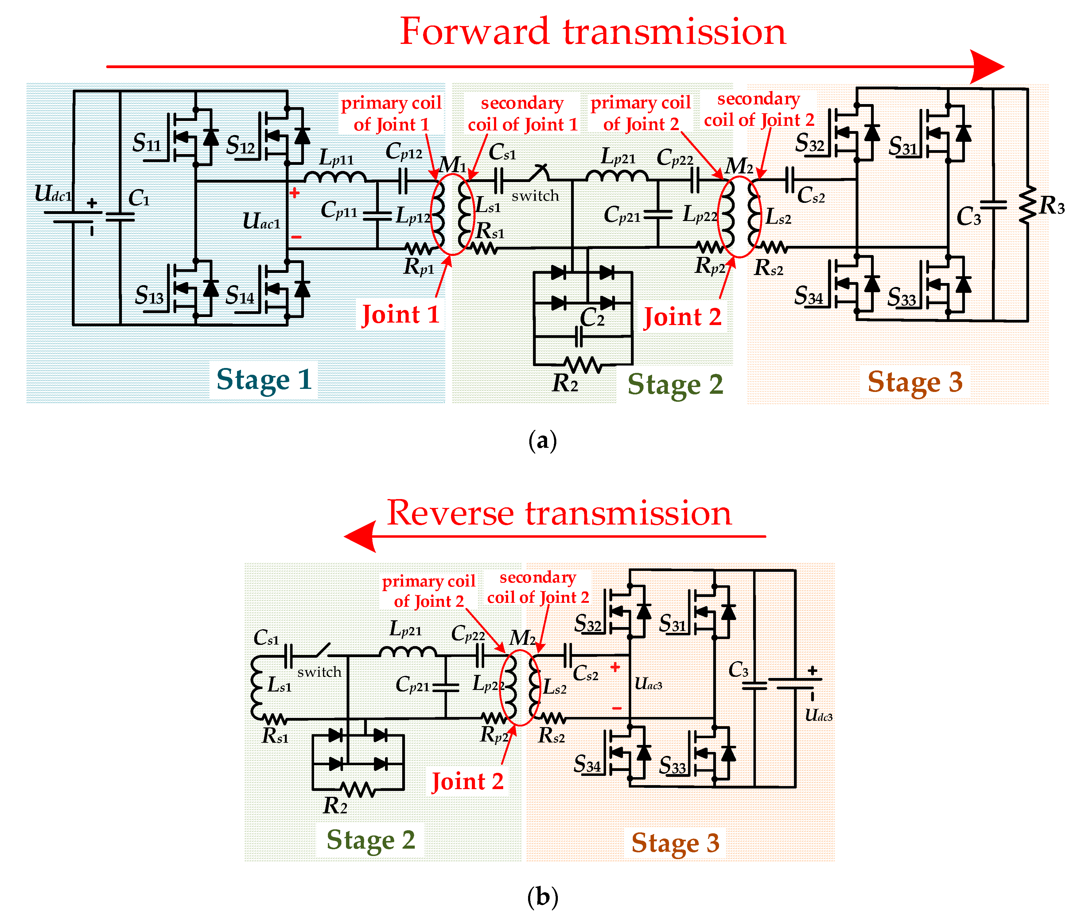
Figure 2.
Mode A.
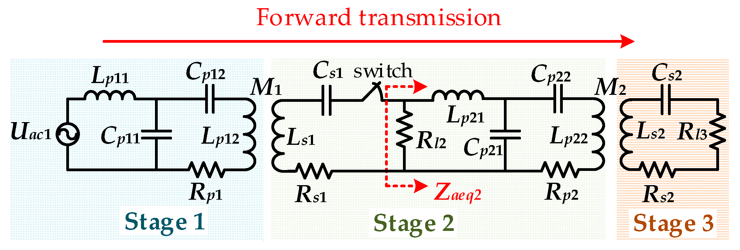
Figure 3.
Mode B.
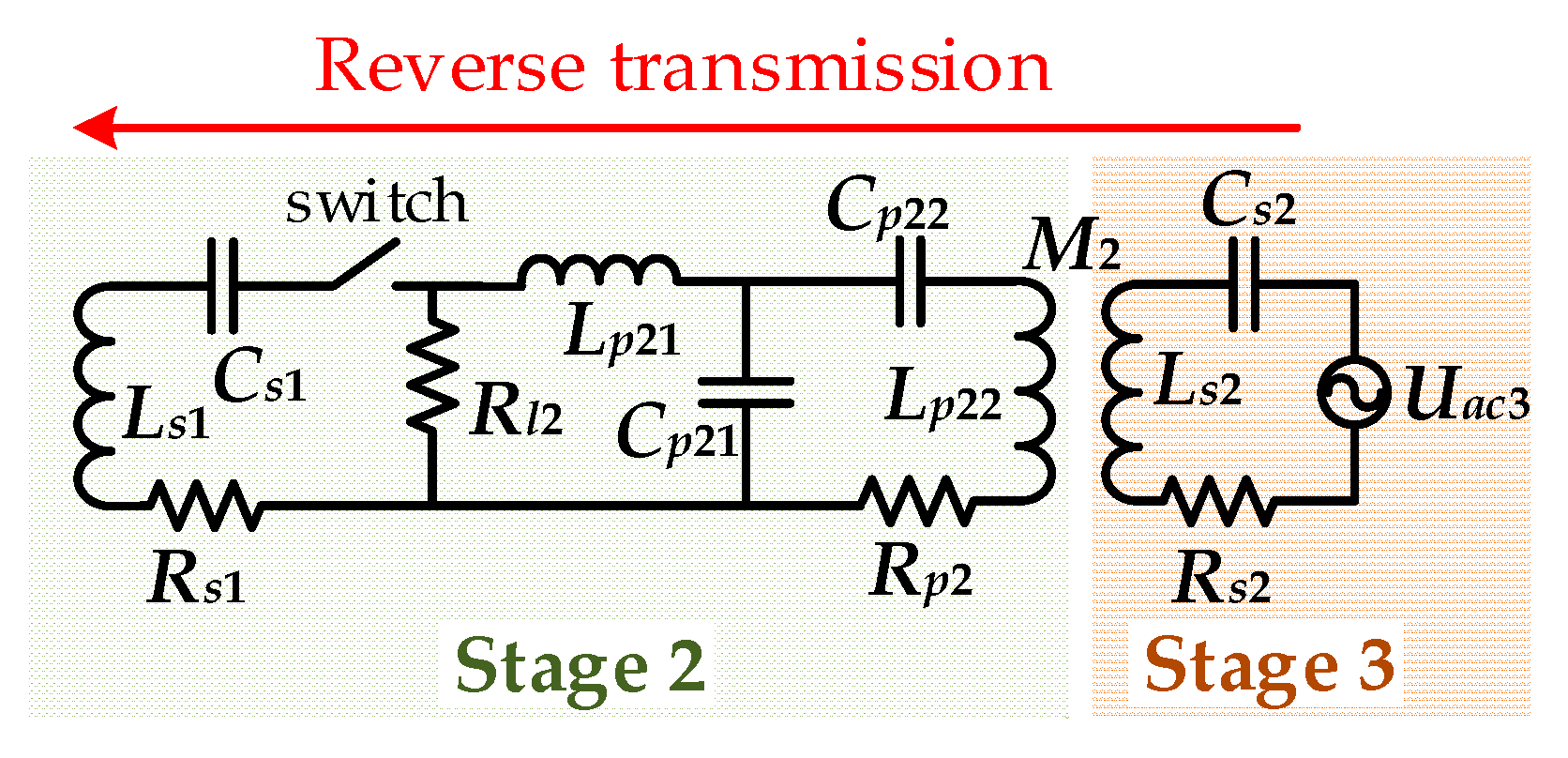
Figure 4.
The variation of the output voltages with the loads in Mode A. (a) The variation of Uao2 with R2 and R3; (b) the variation of Uao3 with R2 and R3.
Figure 4.
The variation of the output voltages with the loads in Mode A. (a) The variation of Uao2 with R2 and R3; (b) the variation of Uao3 with R2 and R3.
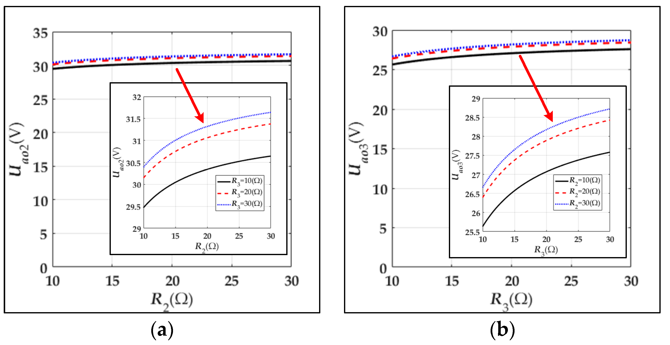
Figure 5.
The variation of the output voltages with the mutual inductances in Mode A. (a) The variation of Uao2 with M1 and M2; (b) the variation of Uao3 with M1 and M2.
Figure 5.
The variation of the output voltages with the mutual inductances in Mode A. (a) The variation of Uao2 with M1 and M2; (b) the variation of Uao3 with M1 and M2.
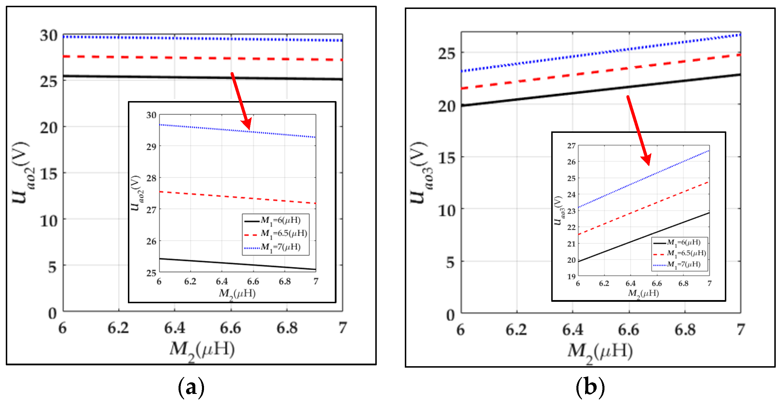
Figure 6.
The variation of the output voltage with the mutual inductance and the load in Mode B.
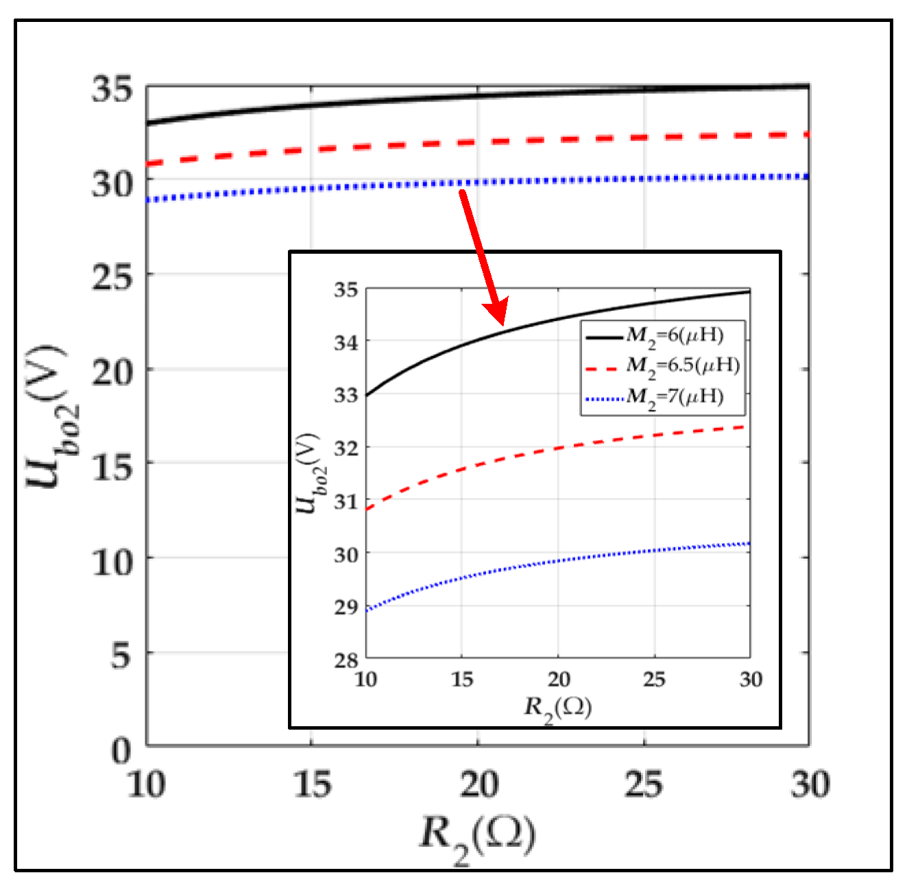
Figure 7.
The variation of the efficiency η with the mutual inductances and the loads in Mode A. (a) The variation of η with R2 and R3; (b) the variation of η with M1 and M2.
Figure 7.
The variation of the efficiency η with the mutual inductances and the loads in Mode A. (a) The variation of η with R2 and R3; (b) the variation of η with M1 and M2.

Figure 8.
The variation of the efficiency η with the mutual inductance and the load in Mode B.
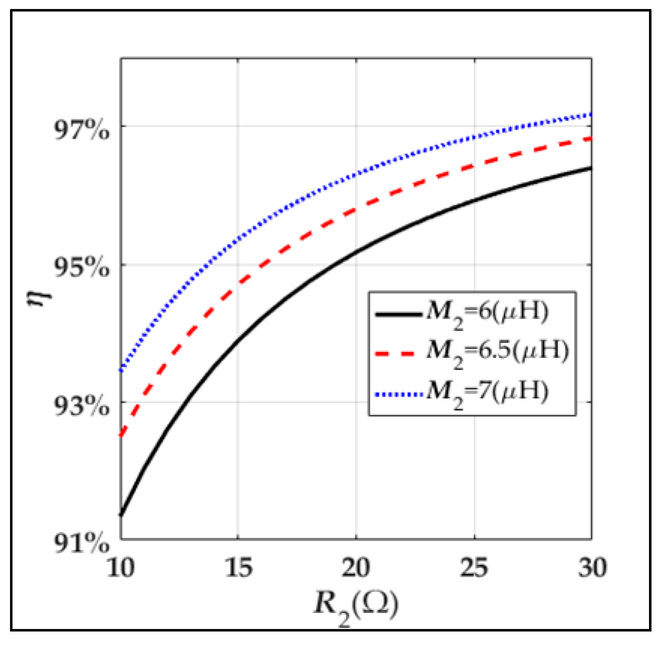
Figure 9.
The variation of the loss PLoss with the loads and the mutual inductances in Mode A. (a) The variation of PLoss with R2 and R3; (b) the variation of PLoss with M1 and M2.
Figure 9.
The variation of the loss PLoss with the loads and the mutual inductances in Mode A. (a) The variation of PLoss with R2 and R3; (b) the variation of PLoss with M1 and M2.
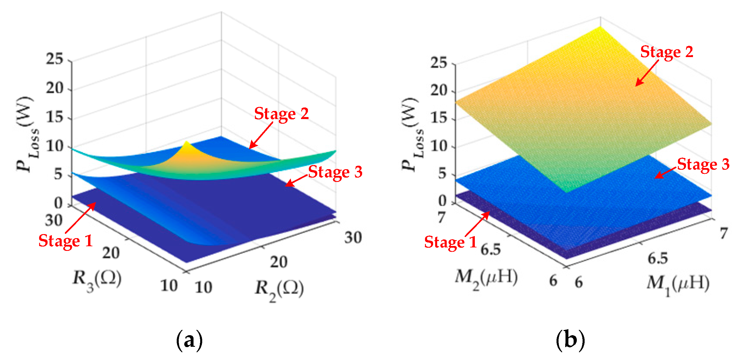
Figure 10.
The variation of the loss PLoss with the load and the mutual inductance in Mode B. (a) The loss analysis of Stage 2; (b) the loss analysis of Stage 3.
Figure 10.
The variation of the loss PLoss with the load and the mutual inductance in Mode B. (a) The loss analysis of Stage 2; (b) the loss analysis of Stage 3.

Figure 11.
The flowchart of the topology parameter design.
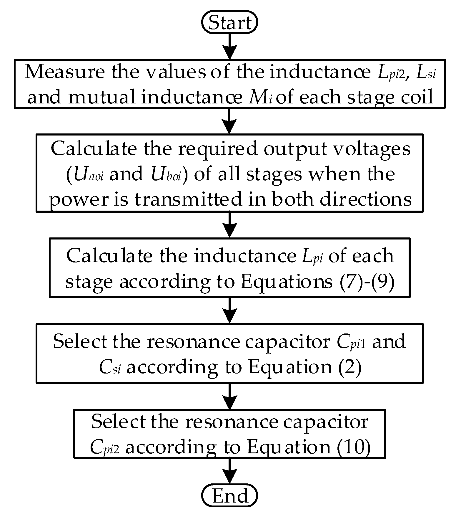
Figure 12.
Experimental setup.

Figure 13.
The variation of output voltages and input current with the loads. (a) R3 = 30 Ω, and R2 varies from 30 to 10 Ω; (b) R3 = 10 Ω, and R2 varies from 30 to 10 Ω; (c) R2 = 30 Ω, and R3 varies from 30 to 10 Ω; (d) R2 = 10 Ω, and R3 varies from 30 to 10 Ω.
Figure 13.
The variation of output voltages and input current with the loads. (a) R3 = 30 Ω, and R2 varies from 30 to 10 Ω; (b) R3 = 10 Ω, and R2 varies from 30 to 10 Ω; (c) R2 = 30 Ω, and R3 varies from 30 to 10 Ω; (d) R2 = 10 Ω, and R3 varies from 30 to 10 Ω.
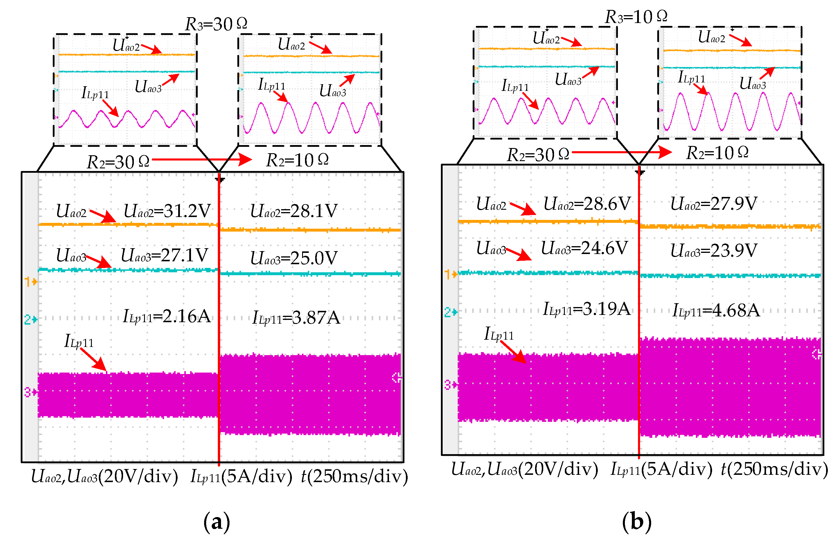

Figure 14.
The variation of output voltages and input current with the rotation of secondary coils, and the rotation schematic of the secondary coils. (a) The variation of output voltages and input current with the rotation of secondary coils; (b) the rotation schematic of the secondary coils.
Figure 14.
The variation of output voltages and input current with the rotation of secondary coils, and the rotation schematic of the secondary coils. (a) The variation of output voltages and input current with the rotation of secondary coils; (b) the rotation schematic of the secondary coils.
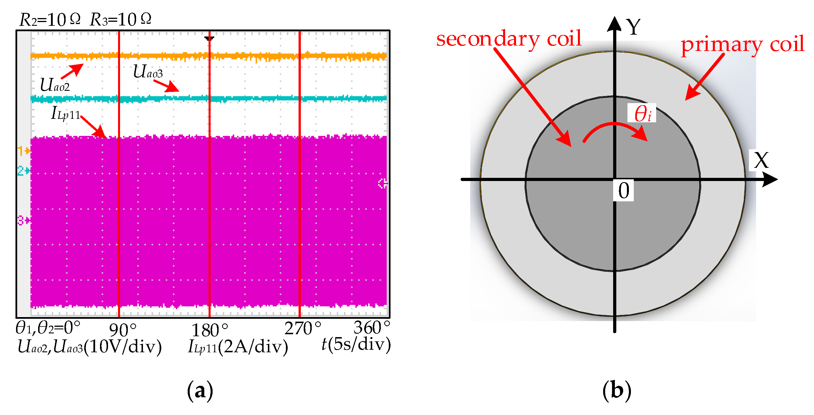
Figure 15.
The variation of output voltage and input current with the load.
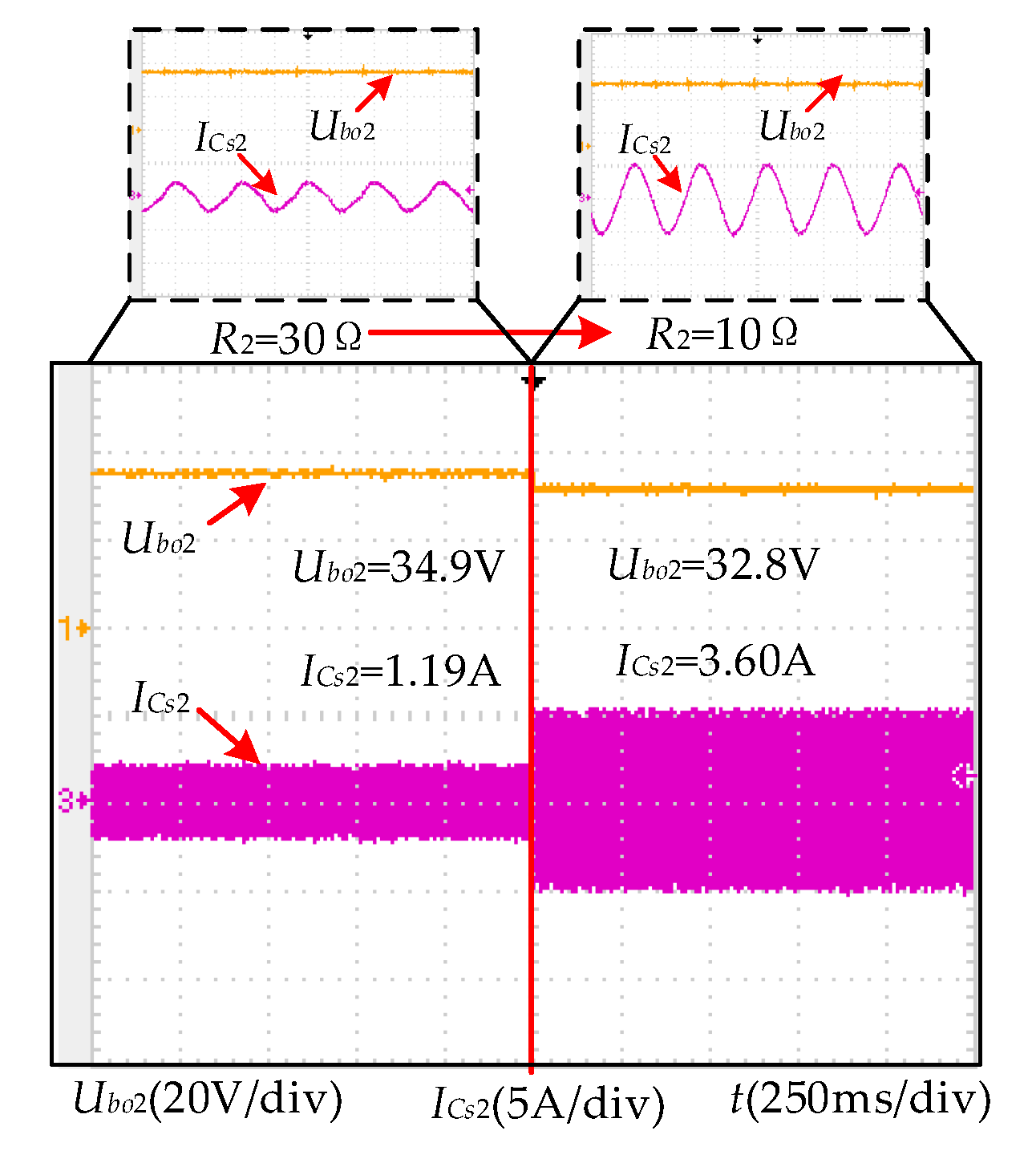
Figure 16.
The variation of output voltage and input current with the rotation of the secondary coil.
Figure 16.
The variation of output voltage and input current with the rotation of the secondary coil.

Table 1.
Forward transmission.
| The output voltage of Rl2 | |
| The output voltage of Rl3 | |
| Output power | |
| Efficiency |
Table 2.
Reverse transmission.
| The output voltage of Rl2 | |
| Output power | |
| Efficiency |
Table 3.
Experimental parameters.
| Parameters | Value | Parameters | Value |
|---|---|---|---|
| Udc1 | 35 V | Udc3 | 35 V |
| f | 500 kHz | Lp11 | 6.4 μH |
| Cp11 | 15.8 nF | Lp12 | 18.6 μH |
| Cp12 | 8.3 nF | Ls1 | 6.86 μH |
| Cs1 | 14.8 nF | M1 | 6.68 μH |
| Rp12 | 0.54 Ω | Rs1 | 0.13 Ω |
| Lp21 | 7.2 μH | Cp21 | 14 nF |
| Lp22 | 18.1 μH | Cp22 | 9.3 nF |
| Ls2 | 6.88 μH | Cs2 | 14.8 nF |
| M2 | 6.68 μH | Rp22 | 0.52 Ω |
| Rs2 | 0.13 Ω | R2 | 10 Ω/30 Ω |
| R3 | 10 Ω/30 Ω | - | - |
Table 4.
The output power and the efficiency.
| R2 (Ω) | R3 (Ω) | Output Power (W) | Efficiency (η) | |
|---|---|---|---|---|
| Mode a | 30 | 30 | 56.9 | 86.3% |
| 10 | 30 | 99.8 | 83.9% | |
| 30 | 10 | 87.8 | 79.6% | |
| 10 | 10 | 135.0 | 76.9% | |
| Mode b | 30 | - | 40.6 | 85.7% |
| 10 | - | 107.6 | 80.7% |
© 2020 by the authors. Licensee MDPI, Basel, Switzerland. This article is an open access article distributed under the terms and conditions of the Creative Commons Attribution (CC BY) license (http://creativecommons.org/licenses/by/4.0/).
Share and Cite
MDPI and ACS Style
Wu, J.; Wang, Z.; Dai, X. Constant Output-Voltage Design for Bi-Directional Wireless Power Transfer System with Multiple Stages. Energies 2020, 13, 3739. https://doi.org/10.3390/en13143739
AMA Style
Wu J, Wang Z, Dai X. Constant Output-Voltage Design for Bi-Directional Wireless Power Transfer System with Multiple Stages. Energies. 2020; 13(14):3739. https://doi.org/10.3390/en13143739
Chicago/Turabian StyleWu, Jinde, Zhihui Wang, and Xin Dai. 2020. "Constant Output-Voltage Design for Bi-Directional Wireless Power Transfer System with Multiple Stages" Energies 13, no. 14: 3739. https://doi.org/10.3390/en13143739
Note that from the first issue of 2016, this journal uses article numbers instead of page numbers. See further details here.