Article

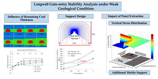
Numerical Analysis of Longwall Gate-Entry Stability under Weak Geological Condition: A Case Study of an Indonesian Coal Mine

1
Department of Earth Resources Engineering, Faculty of Engineering, Kyushu University, Fukuoka 819-0395, Japan
2
Department of Geo-Resources and Geotechnical Engineering, Institute of Technology of Cambodia, Phnom Penh 12150, Cambodia
3
MM Nagata Coal Tech Co., Ltd., Tokyo 140-0002, Japan
*
Author to whom correspondence should be addressed.
Energies 2020, 13(18), 4710; https://doi.org/10.3390/en13184710
Submission received: 28 July 2020 / Revised: 2 September 2020 / Accepted: 3 September 2020 / Published: 10 September 2020
(This article belongs to the Special Issue Green Coal Mining Techniques 2020)

Abstract

:
The present research primarily focuses on the investigation of gate-entry stability of longwall trial panel under weak geological condition in Indonesia coal mine by means of numerical analysis. This work aims at identifying appropriate roof support at 100 m and 150 m of depth during gate development. Due to depth depending competency of dominant rock, the stability of gate-entry at 100 m of depth can be optimized by leaving at least 1 m of remaining coal thickness (RCT) above and below the gate-entry. The appropriate support for the trial panel gate-entry is steel arch SS540 with 1 m and 0.5 m spacing for 100 m and 150 m of depth, respectively. The influence of panel excavation on gate-entry is also discussed. Regarding the aforementioned influence, the utilization of additional gate mobile support is recommended at least 10 m from the longwall face.

Graphical Abstract

1. Introduction

The majority of coal resources in Indonesia is situated in weak geological condition region [1,2,3]. This weak geological condition presents a big challenge in developing underground longwall coal mines. Since the beginning, the development of underground longwall coal mine in Indonesia has adopted a general longwall guideline developed from other major coal producing countries including the U.S., Australia, and China. As a result, the utilization of bolt-type support is very common for gate-entry support in Indonesia. The instability of gate-entry has become one of the major ground issues for longwall mine development in Indonesia. This problem is mainly caused by inadequate support design and lack of understanding of ground behavior during the longwall mining development. The weak rock usually refers to a group of rock whose uniaxial compressive strength falls below 25MPa [4,5]. This property causes the weak rock to behave totally different from hard rock corresponding to longwall mining operation in various aspects including roof caving behavior, subsidence, abutment stress distribution [6,7,8,9]. For this particular research, the stability of gate-entry is linked directly to the behavior of the abutment stress distribution. In general, for all underground opening structures, there are three areas surrounding that opening [8,9]. These include stress decrease area, which is located above the opening, stress increase area, which contains the highest peak stress at a certain distance from the opening, and the initial stress area, which marks the end of stress disturbance from the opening. The softer the rock measure, the farther the peak stress is located from the opening. This could cause a problem in longwall mining, as the abutment stress link directly to the stability of the gate-entry. Weak rock also reduces the efficiency of active support such as tensioned rockbolts and cablebolts, which are the most common support systems in longwall mining while favoring passive support such as steel arch and shotcrete [10,11,12,13,14].
In longwall mining, gate-entries provide access for mining equipment transportation to the longwall face and carried out coal production from the longwall face to the surface. Gate-entries also work as a major component of longwall ventilation system to remove the toxic gases as well as dust particles released during panel extraction [15]. Thus, the stability of gate-entry is really crucial to ensure a smooth longwall mining operation. Two major aspects influence the stability of gate-entry [16]. First is during the excavation operation of the gate-entry itself due to stress redistribution around the gate opening. Second is during longwall panel extraction. During this operation, a large portion of coal is excavated, which causes the roof above to fracture and fall down. This fractured zone is called the goaf area. This operation results in a huge stress redistribution to occur in the surrounding area. As shown in Figure 1, due to the development of fracture zone in the goaf area, overburden stress is redistributed into the rib side around the goaf area. This phenomenon causes high abutment stress along longwall face and peak stress at both edges of the longwall face [17]. Furthermore, this phenomenon affects the stability of the gate-entry as both gate-entry of the longwall is connected to the edge of the longwall face where the peak stress is located.
There are multiple factors that limit mining height in the longwall mine design, in which the weak geological condition is also included [18]. In the case where the thickness of the coal seam is significantly thicker than the mining height, there must be some portion of coal left above and below the excavation area. This remained portion of coal is quite advantageous for improving the stability of the longwall mine, especially when the surrounding rock is relatively weaker than the remained coal. There are abundant research works that study on longwall mining development in thick coal seam [18,19,20,21]. Some also integrate weak geological conditions [1,22]. However, none of them have discussed the influence of remaining coal thickness (RCT) on the stability of the longwall development.
This paper discusses the stability of gate entry under various stages of longwall development with two different depths of 100 m and 150 m. This research involves investigating and modeling a trial panel from the actual mine site in Indonesia to evaluate the appropriate support system for the gate-entry. The first part of the paper focuses on the influence of remaining coal thickness on improving the stability of gate-entry. This part is targeted only at a depth of 100 m, as claystone in this area is relatively weaker than coal. The second part of this research is to evaluate the appropriate support system for the trial panel during gate-entry development for 100 m and 150 m of depth. The last section of this research work is to investigate the gate-entry stability under the influence of longwall panel extraction. This operation causes the increment of the stress surrounding gate-entry, which is located near the longwall face. This stress might exceed the maximum support capacity of the designed support, which results in instability of gate-entry. Additional mobile support is necessary for maintaining the stability of the gate-entry during panel extraction. The length of the additional support along the gate is also evaluated in this section.

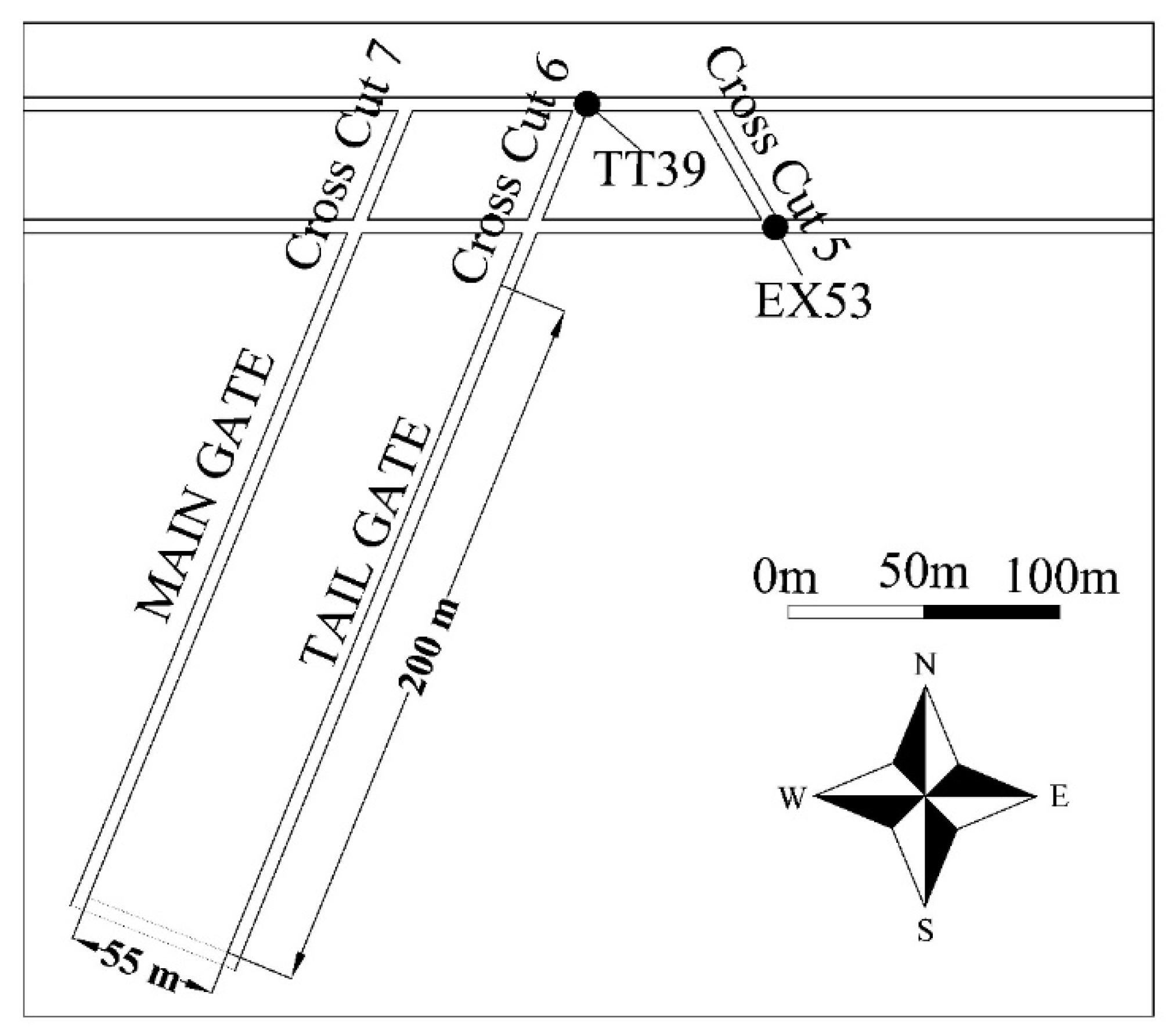
2. General Overview of the Targeted Indonesia Coal Mine

The research is conducted in a coal mine, which is situated in the area of Kutai Kertanegara of East Kalimantan Island. The analytical of drill hole core samples revealed that the study area has a monocline structure with claystone as the dominant rock. The dip of the coal seam range between 3° and 13° and the thickness of the coal seam can reach up to almost 10 m in a certain seam. This mine selected the longwall mining method for coal recovery.
The development of longwall mining is sited in a weak geological area. The competence of the dominant rock claystone is related to the depth in which the shallower depth zone has relatively lower strength. The recent development of trial panel which extend between 100 m to 150 m of depth has been gone under operation. Figure 2 shows the top view of the trial panel layout. The dimension of this trial panel is 55 m width by 200 m length with 3 m height. Extensometer (EX) and telltale (TT) are installed in the roof of the gate in order to monitor the deformation of the gate roof.

3. Modeling

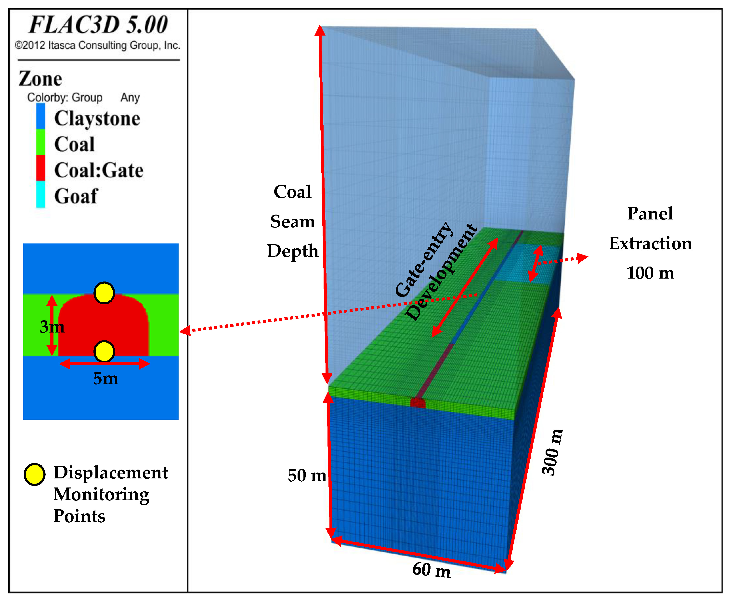
3.1. General Model Description

The trial panel is modeled in FLAC3D 5.00 software (Fast Lagrangian Analysis of Continua in 3 Dimensions) from Itasca Consulting Group, Inc. Only half of the trial panel, along the panel length, is modeled to save running time. Mohr-Coulomb constitutive model is adopted for all numerical models in this research. Due to the natural incline of the coal seam, the depth of this trial panel ranges from 100 m to 150 m. Both depths are adopted as case studies. General dimensions of the model can be described as 153 m × 60 m × 300 m for 100 m of depth and 203 m × 60 m × 300 m for 150 m of depth as shown in Figure 3. Mining height is 3 m of the coal seam, which is surrounded by dominant rock claystone as the roof and floor. Figure 4 shows the installation of the steel arch in the model. Beam structural elements are used to model steel arch for roof support along the gate-entry. According to the FLAC3D manual of Itasca_Consulting_Group [23], beam structure element is a straight two-noded, finite elements with six degrees of freedom per node. Beam structure behaves as a linearly elastic structure with no failure limit. Each steel arch is modeled from a collection of beams. Since the steel arch are modeled to attach to the inner part of the excavated gate in such a way that the movement or deformation of the grid will generate force and bending moments develop within the beam structure.
As aforementioned, the result obtained from a series of laboratory tests show that the competence of claystone is related to the depth where relatively lower strength rock can be found in shallower depth. As a result, properties of the claystone are separated into two categories based on the depth. The rock mechanical properties are listed in Table 1. Steel support, composed of three main parts jointed together by eight hex bolts, is utilized for supporting gate-entry. The material type of steel SS540, which has a yield strength of 540 MPa, is selected as the material for the steel arch support. Its mechanical properties are listed in Table 2. Case studies for investigating the influence of the remaining coal thickness are shown in Figure 5. The thickness of the remaining coal ranges from 0 m to 2.5 m above and below the gate. A series of parametric studies are conducted to discuss the appropriate support design under different conditions such as stress ratio K: 1, 1.5, and 2, mining depth: 100 m and 150 m, support spacing: 0.5 m and 1 m. The numerical modeling steps includes the following:
  • Construct model geometry (half-width of the panel is modeled to reduce the model analyzing time).
  • Apply boundary condition, assign mechanical properties, determine initial stress condition, and analyze for the initial state.
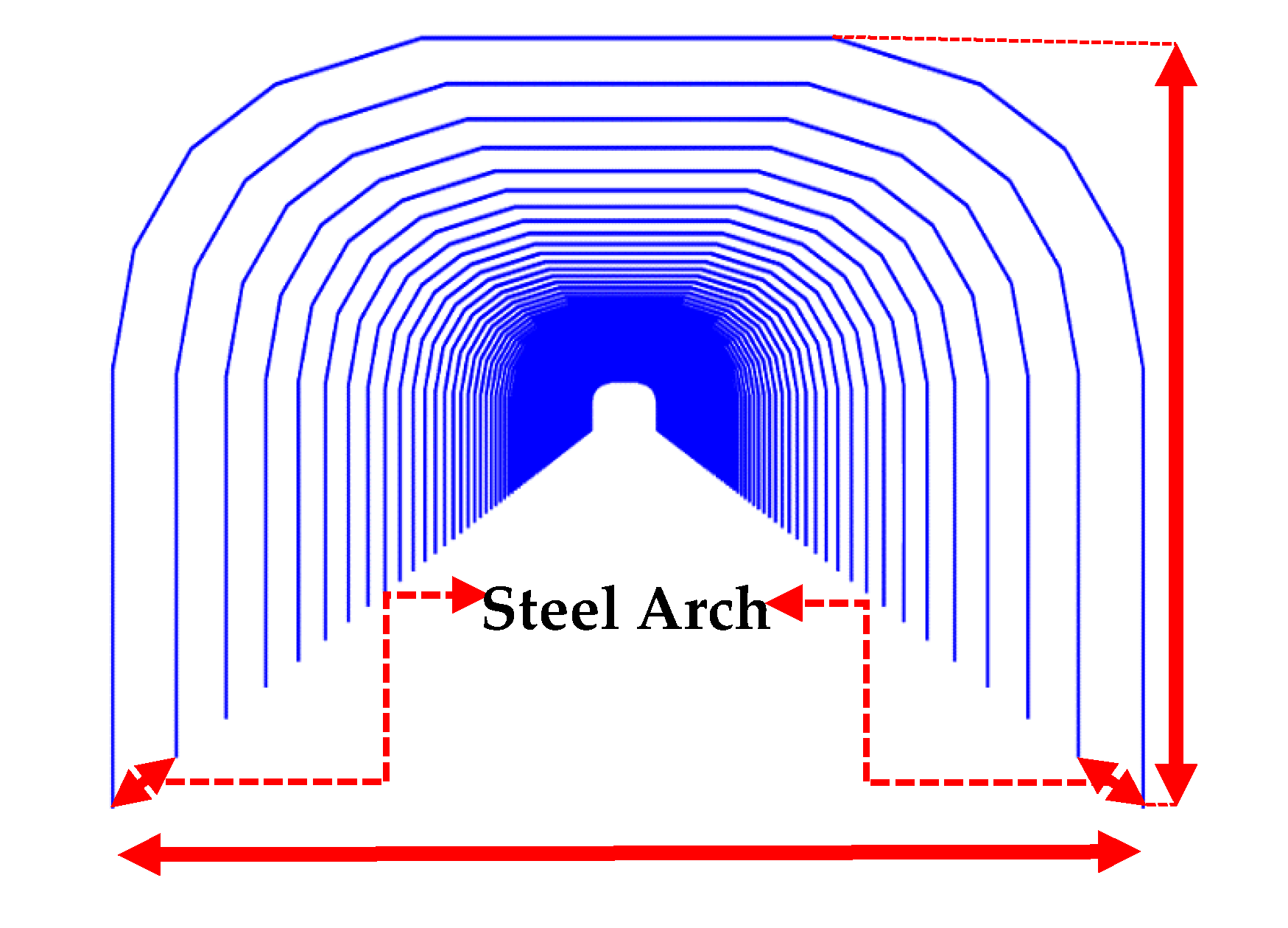
  • Excavate gate-entry and install steel arch 200 m.
  • Monitor maximum axial stress of steel arch and roof displacement
  • Excavate longwall panel for 100 m.
  • Monitor maximum support axial stress
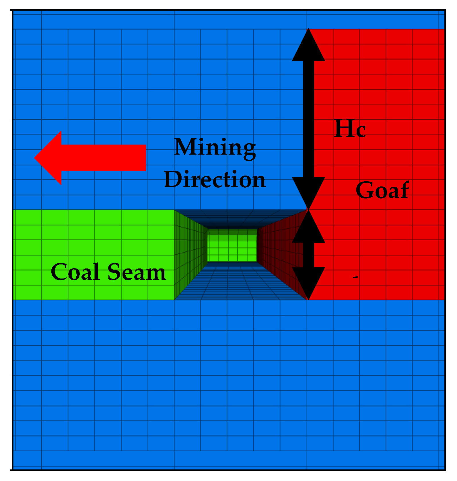
3.2. Goaf Modelling

Goaf is the fragmentation of the immediate roof behind the longwall face caused by the advancing of longwall excavation [24]. The most abutment stress in the excavation area is carried by the pillar. However, a small amount of abutment stress will remain to be carried by goaf [25].
There are several methods to simulate the behavior of goaf. According to Song and Chugh [26], goaf can be simulated using goaf loading characteristics. However, the challenge of quantitative measurements of goaf loading is high due to the inaccessibility in the goaf area. Many assumptions have to be made for obtaining goaf loading characteristics. It is also possible to simulate the longwall panel retreat without considering goaf [27]. The simulation consisted of removing coal from the panel without filling back any material. This space of the null zone material is kept during the analysis of the model. However, this method is applicable only for a small null space. When this null space becomes larger and larger during the advancing of the longwall face, it is possible that the unbalance force in the model is converged into none-zero value. According to the FLAC3D manual of Itasca_Consulting_Group [23], this indicates failure and plastic flows occur within the model. Another possibility when adopting this method is the divergence of the unbalance force, which will affect the accuracy of the analysis.
There is another way of modeling goaf. After panel excavation, a softer material is used to replace both the panel and the caved zone above the excavation area to simulate the collapse of the immediate roof [3,28,29]. The caved zone height can be assessed by using Equation (1):
H C = 100 h c 1 h + c 2
where Hc represents the height of the caved zone, h is mining height, and c1 and c2 are coefficients depending on lithology. Table 3 presents the value of the lithology coefficient depending on rock competence. This paper adopts this method for modeling goaf. According to this equation, the height of the caved zone can be estimated to be 5.93 m. Figure 6 shows the schematic view of the longwall face and goaf during panel extraction.

3.3. Modeling for Shield Support

There is a couple of ways of simulating shield support specifically for FLAC3D. The first method is using beam structural elements to model the shield support [30]. However, it is really complex when it comes to assigning the properties of the beam to simulate different setting pressures of shield support. Song et al. [31] came up with a simple and effective method of applying pressure to the roof and the floor of the longwall face to simulate different setting pressure of the shield support. The second method is adopted to simulate shield support for this research.
Due to the fact that this trial panel is in the early development stage, the type and capacity of the shield support for the longwall face are still being considered. For this reason, a random ZY6800/16/32 is selected to support the longwall face for this study. According to Song et al. [31], these shields are equipped with 6800 kN or 23.6 MPa loading capacity, and shield height range from 1.6 m to 3.2 m. These shield support legs are attached at the two-thirds length of the canopy from the tip. As a result, stress is concentrated at the end part of the canopy. For footplates, on the other hand, the leg position is located at the center length of the plate, which generates constant stress distribution at the base of the canopy. Figure 7 shows the development of shield support distribution pressure used in this research for simulations, which is based on the actual distribution pressure profile of ZY6800/16/32. Shield setting pressure is selected to be 6000 kN.

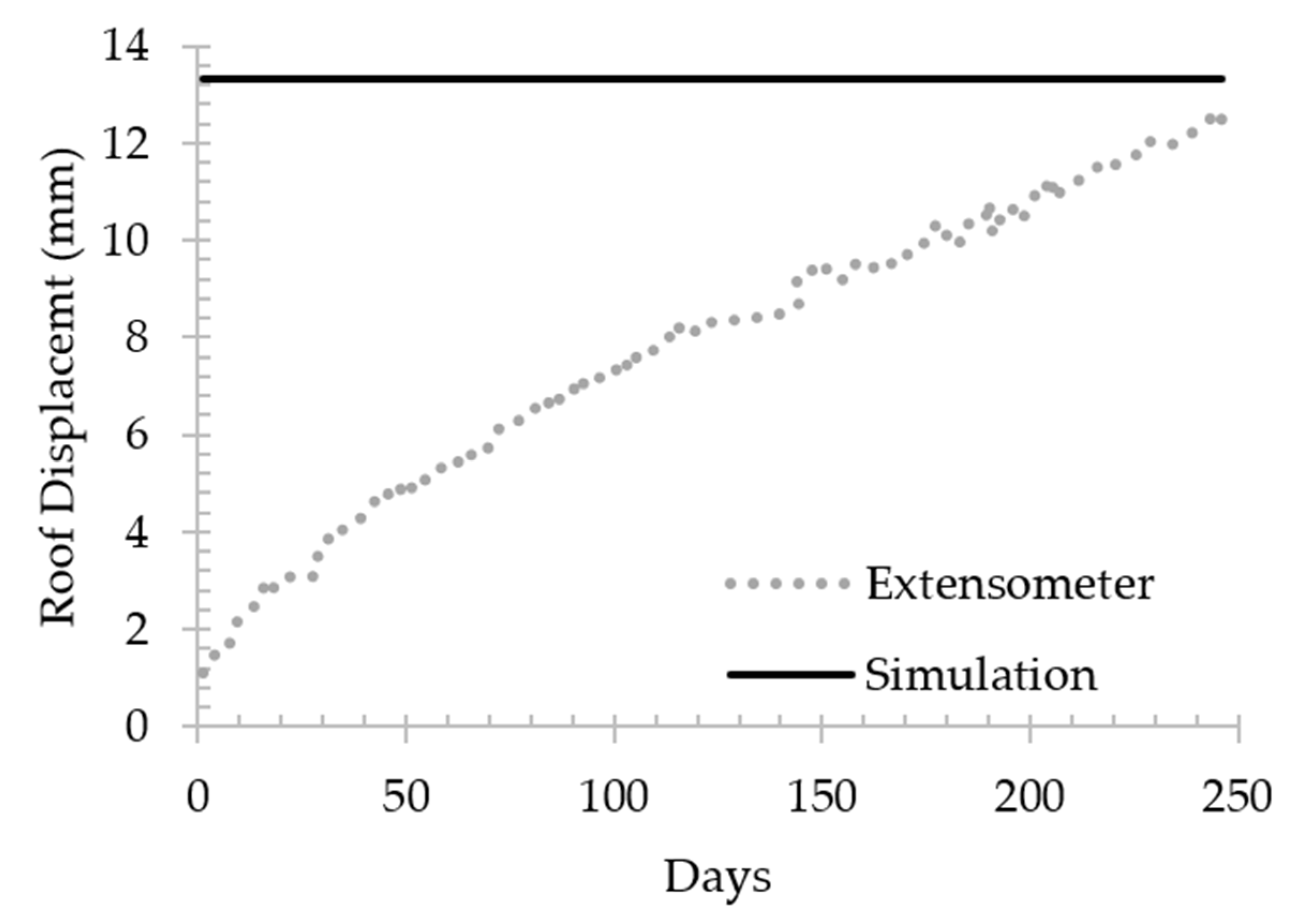
3.4. Model Validation

The simulation result is validated with the field measurement results for displacement. Two types of roof displacement monitoring devices are installed along the main roadway, which include a telltale (TT) and extensometer (EX). TT39 and EX53 are used for this validation; the installation location can be found in Figure 2. The installation location is at the T-section area, around 100 m from the surface. The rock surrounding the gate is claystone. One meter of support spacing is used to support this gate. These devices are installed after gate development operation by drilling a small vertical borehole into the roof of the gate around 6 m in length and anchoring these monitoring devices along the borehole. These devices can monitor gate roof movement in this 6 m installed range. Gate roof movement and displacement has been recorded daily in millimeter. The model is constructed in FLAC3D based on the site described above.
The displacement result from the simulation model is used to compare with the results of the extensometer and telltale from the field. Figure 8 shows the comparison of the results between the telltale and simulation model. The total displacement of the simulation result is 13.3 mm. This value is barely distinguishable from the total displacement of telltale, which is 14 mm. The comparison between the displacement results from the simulation model and the extensometer in Figure 9 also shows a great agreement. The maximum roof displacement from the extensometer is 12.6 mm, which is less than a millimeter difference from the simulated result. The result of the extensometer seems to be still increasing and the measured value may exceed the computed value within a certain time. However, this might not be a problem for estimating gate-entry stability during panel operation. The gate-entry is a temporary structure that is expected to collapse at the end of each panel extraction operation. The field monitoring time is more than 200 days. As a result, this period is more than enough to finish the panel extraction operation for a typical panel. The overall comparisons indicate that this model configuration is suitable for predicting rock behavior in this research.

4. Results and Discussions

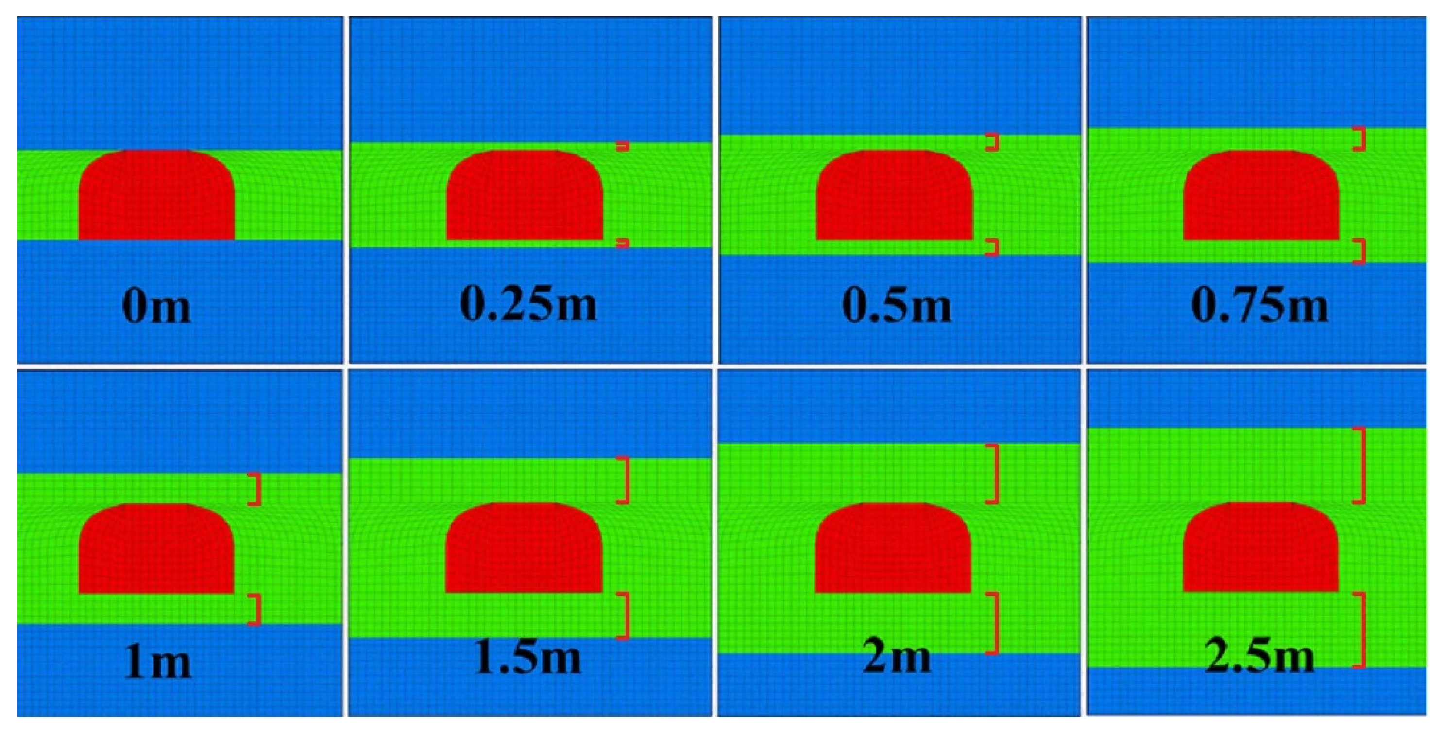
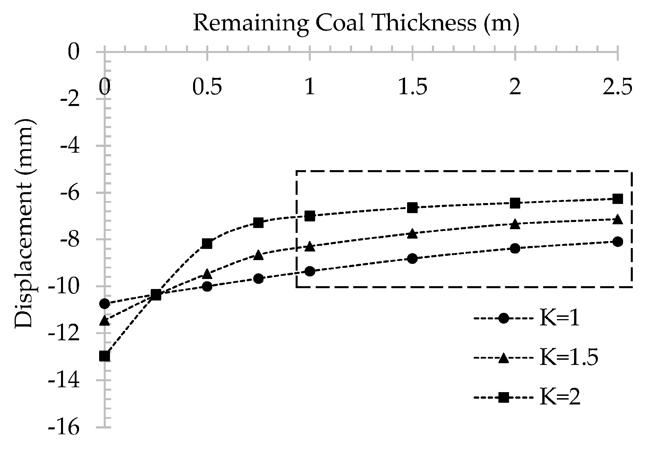
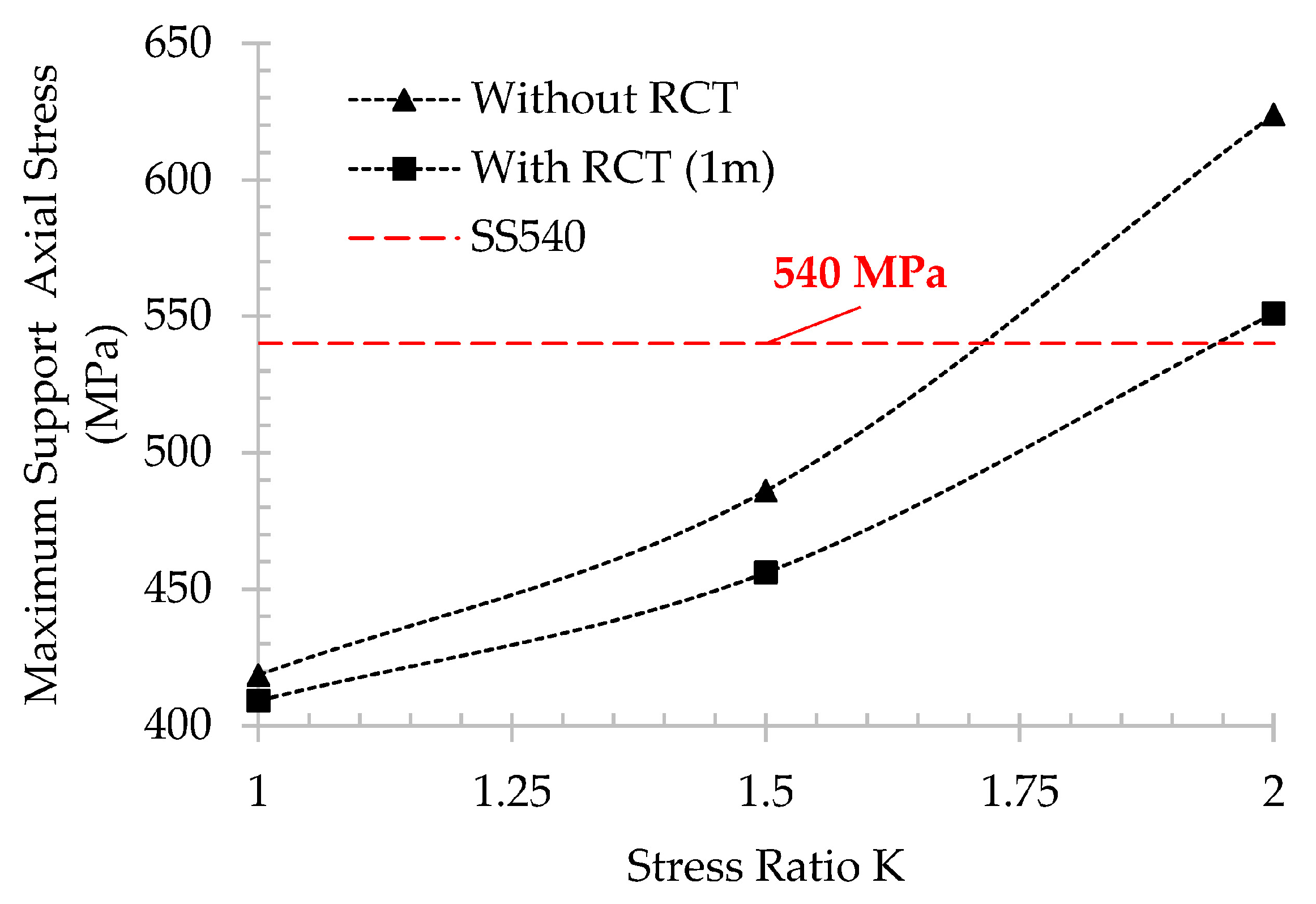
4.1. Stability of Gate-Entry under the Influence of the Remaining Coal Thickness (RCT)

First, the simulation models are constructed to assess the influence of the remaining coal thickness (RCT) on improving gate-entry stability at a depth of 100 m. In order to analyze the pure influence of RCT, gate entry is excavated without any support in the model. After gate excavation, displacement is monitored at the middle point of the roof and floor of the gate-entry as illustrated in Figure 3. The results are shown in Figure 10 and Figure 11. As predicted, the displacement decreases with the increase of RCT.
Figure 10 shows the correlation between roof displacements and remaining coal thickness with different stress ratios, while Figure 11 shows the correlation between floor displacement and remaining coal thickness. The reductions of displacement on the roof are around 2.5 mm, 4.5 mm, and 6.5 mm for stress ratios 1, 1.5, and 2, respectively. For the floor, reductions value for the respective stress ratios are 2.5 mm, 5 mm, and 8.5 mm. It is quite difficult to draw any conclusion from the displacement result obtained from stress ratio 1 due to the fact that the result trend line decreased in a form of constant linear reduction when RCT increased. For bigger stress ratios of 1.5 and 2, both roof and floor results show a noticeably huge decrease of displacement when RCT is between 0 m to 1 m. Above 1 m of RCT, these shrinkages of displacement are very minimal. From these results, it can be said that 1 m of RCT is the optimum thickness for improving gate-entry stability.

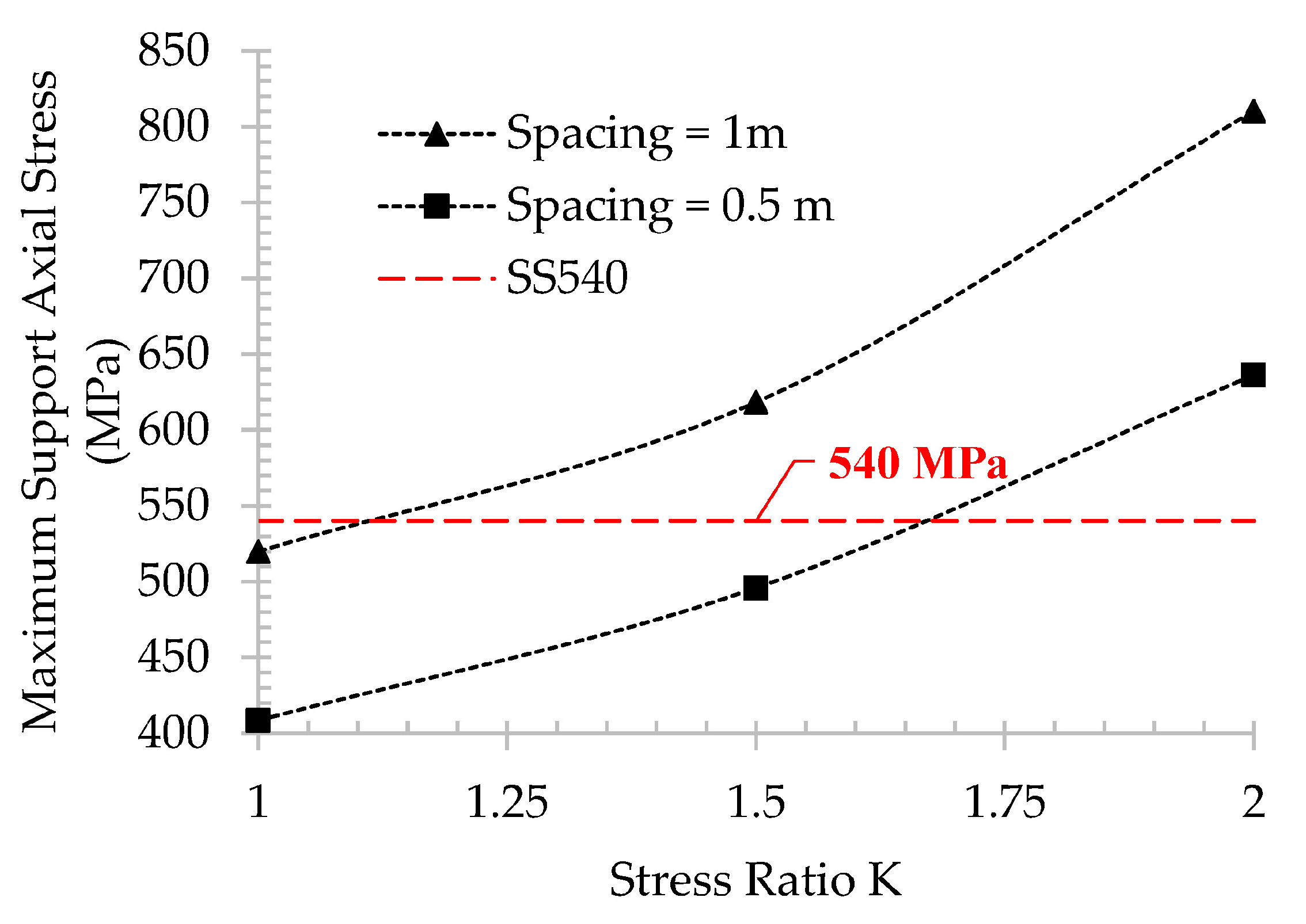
4.2. Gate-Entry Stability during Gate Development

The stability of the gate-entry is maintained by a steel arch support. The results of support axial stress for each case are used for comparing with the support maximum yield strength. If the support axial stress is greater than support yield strength, gate-entry is considered to be in the unstable condition. A wide support spacing of 1 m is adopted for gate-entry at 100 m of depth. According to the previous section, 1 m of RCT is the optimum thickness. The incorporation of RCT influence is only assessed for cases at 100 m of depth. For 150 m of depth, as the competence of coal and claystone are quite similar, RCT does not have any influence on gate-entry. There are two spacings of steel support: 1 m and 0.5 m, which are adopted for 150 m of depth due to the higher stress. The result of the maximum support axial stress of 1 m of RCT and without RCT for 100 m of depth are illustrated in Figure 12. The outcome indicated that for 100 m of depth, if 1 m of RCT is available, the utilization of steel arch SS540 with 1 m spacing to support gate-entry is applicable up to K = 1.9. On the other hand, if RCT is not available, this support is only suitable up to K = 1.6. From this result, we are able to identify the potential reduction of support cost for stress ratios between 1.6 and 1.9. Within this stress ratio range, the existence of RCT can hypothetically enlarge the required support spacing from 0.5 m to 1 m, which translates to a reduction of the support cost by half. Maximum support axial stress for 150 m of depth is shown in Figure 13. According to this figure, 1 m support spacing is capable to maintain the stability of the gate-entry up to K = 1.1, while a narrower spacing of 0.5 m can increase the support capacity to withstand K = 1.6. Higher support capacity is required if the stress ratio is above 1.6, which can be achieved by narrowing the support spacing or incorporate the current steel arch support with a rock bolt or shotcrete.

4.3. Gate-Entry Stability during Panel Extraction

The impact of panel extraction on the stability of gate-entry is crucial in longwall mining study. Generally, the stress increases significantly in some distance along the entry-gate from the longwall face. These over-stress distances are important for optimizing additional mobile support during panel extraction operation.

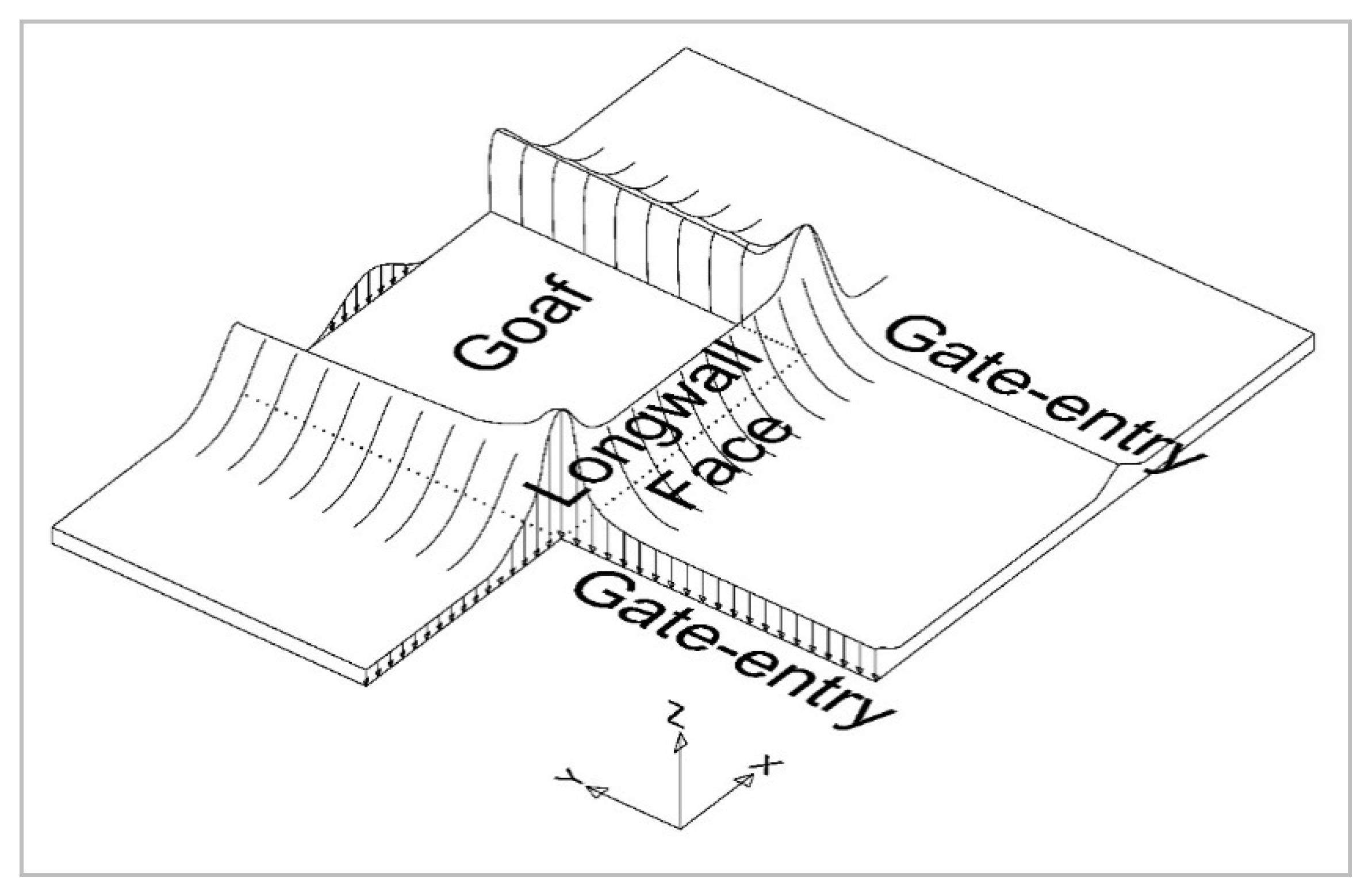
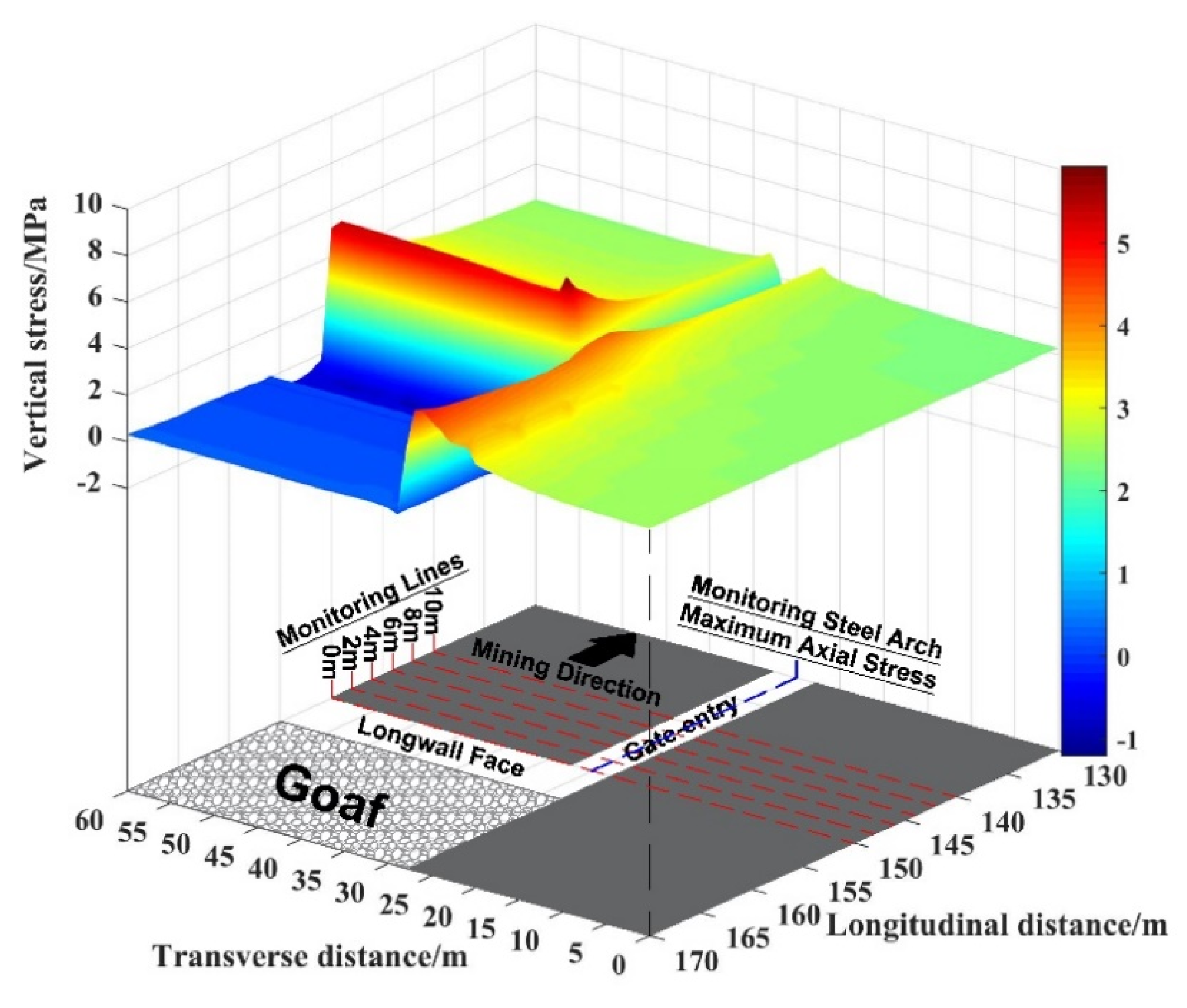
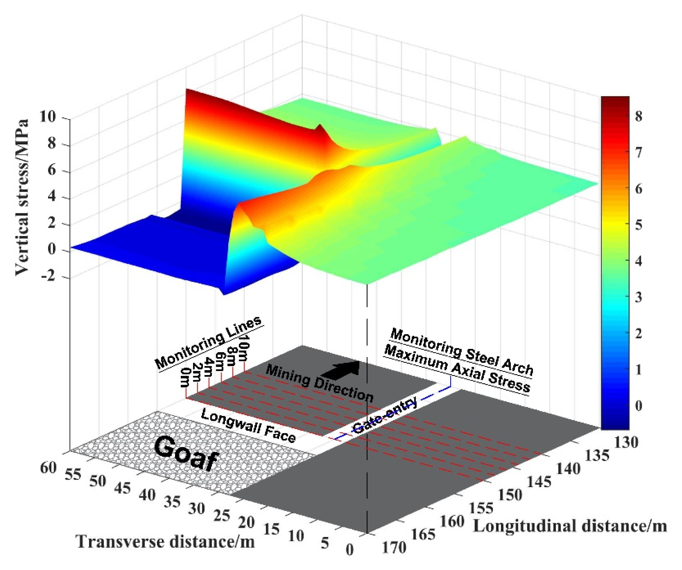
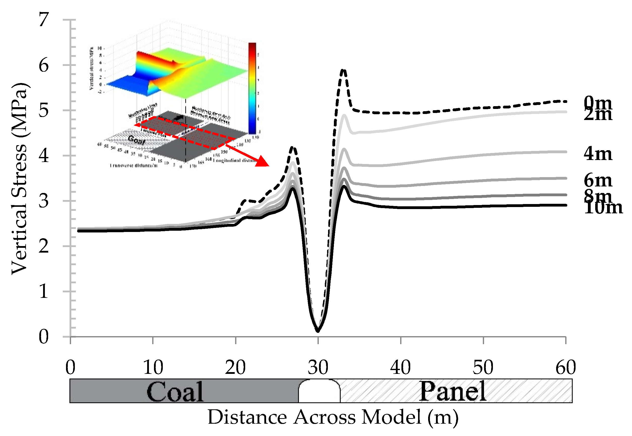
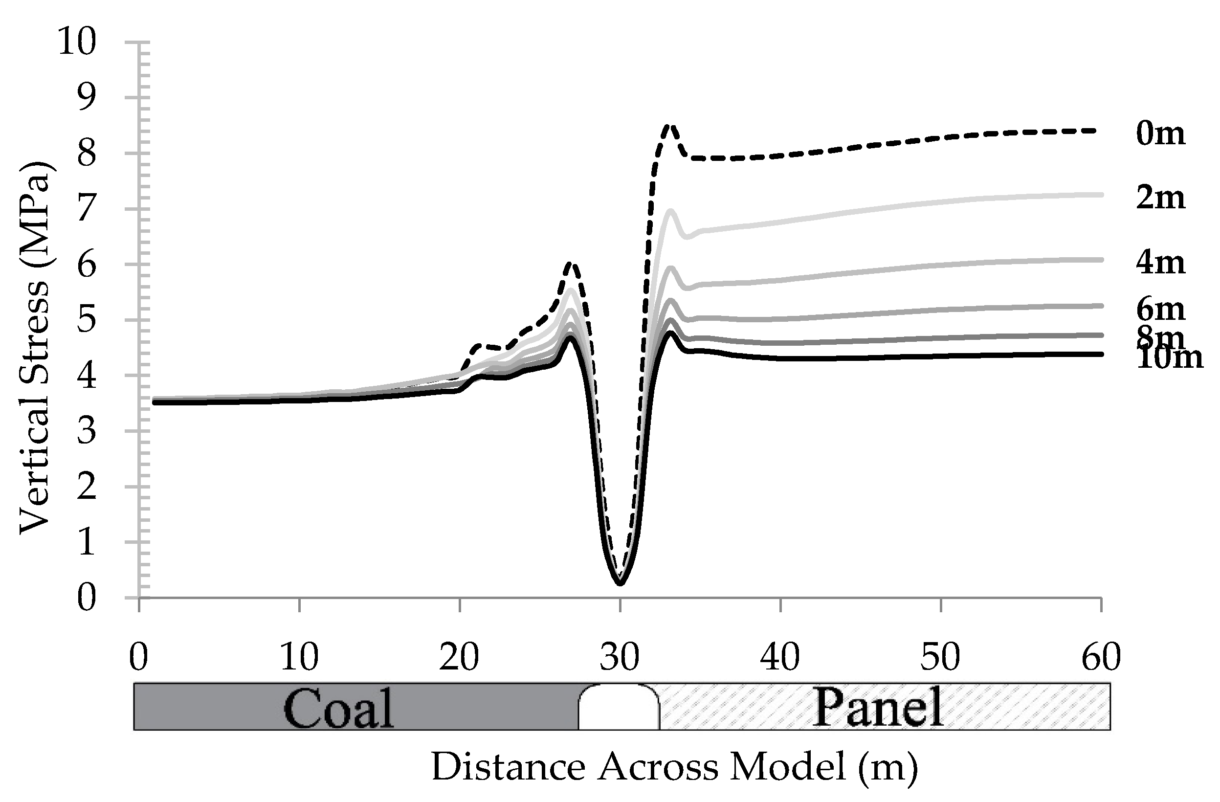
4.3.1. Vertical Stress Distribution

After advancing the longwall face for 100 m, the vertical stress is monitored above the mining panel surround the longwall face. Three-dimensional (3D) schematic plots of vertical stress distributions are shown in Figure 14 and Figure 15 for 100 m and 150 m, respectively. A similar stress distribution can be observed from both schematics, which include stress release in the goaf area, high-stress concentration in the longwall face, and higher peak stress in the corner between the longwall face and gate-entry. Figure 16 and Figure 17 show the vertical stress along the transverse distance, which is monitored from the longwall face range from 0 m to 10 m with an interval of 2 m. The location of the monitoring lines can be found in Figure 14 and Figure 15.
Figure 16 shows vertical stress result in case of 100 m of depth. The observation peak stress of both sides of the gate near to the longwall face is asymmetrical, which is caused by the stress redistribution due to the panel extraction. The highest peak stress at 0 m from longwall face is around 6 MPa on the panel side and 4 MPa on the coal side. When the monitoring line is moved away from the coal face the peak stress for both sides of the gate tend to become more and more symmetrical, which indicates that the influence of the panel extraction operation decrease. Around 10 m distance from the longwall face, the peak of vertical stress becomes almost symmetrical with the peak stress around 3 MPa for both sides of the gate.
The same statement is also true for Figure 17 in case of 150 m of depth. At 0 m from the longwall face, the highest peak of vertical stress is around 8.5 MPa on the panel side and 6 MPa on the coal side. For 10 m distance from the longwall face, the peak stress reduces to 4.5 MPa for both sides of the gate. This nearly symmetrical peak of vertical stress also designates less influence of panel extraction on gate-entry. These results point to the likelihood that the influence of panel extraction is at their highest impact in the longwall face. This influence tends to decrease with the increase of distance from the longwall face. Based on these results of vertical stress analysis, the influence of panel extraction decreases to their minimum from 10 m distance from the longwall face.

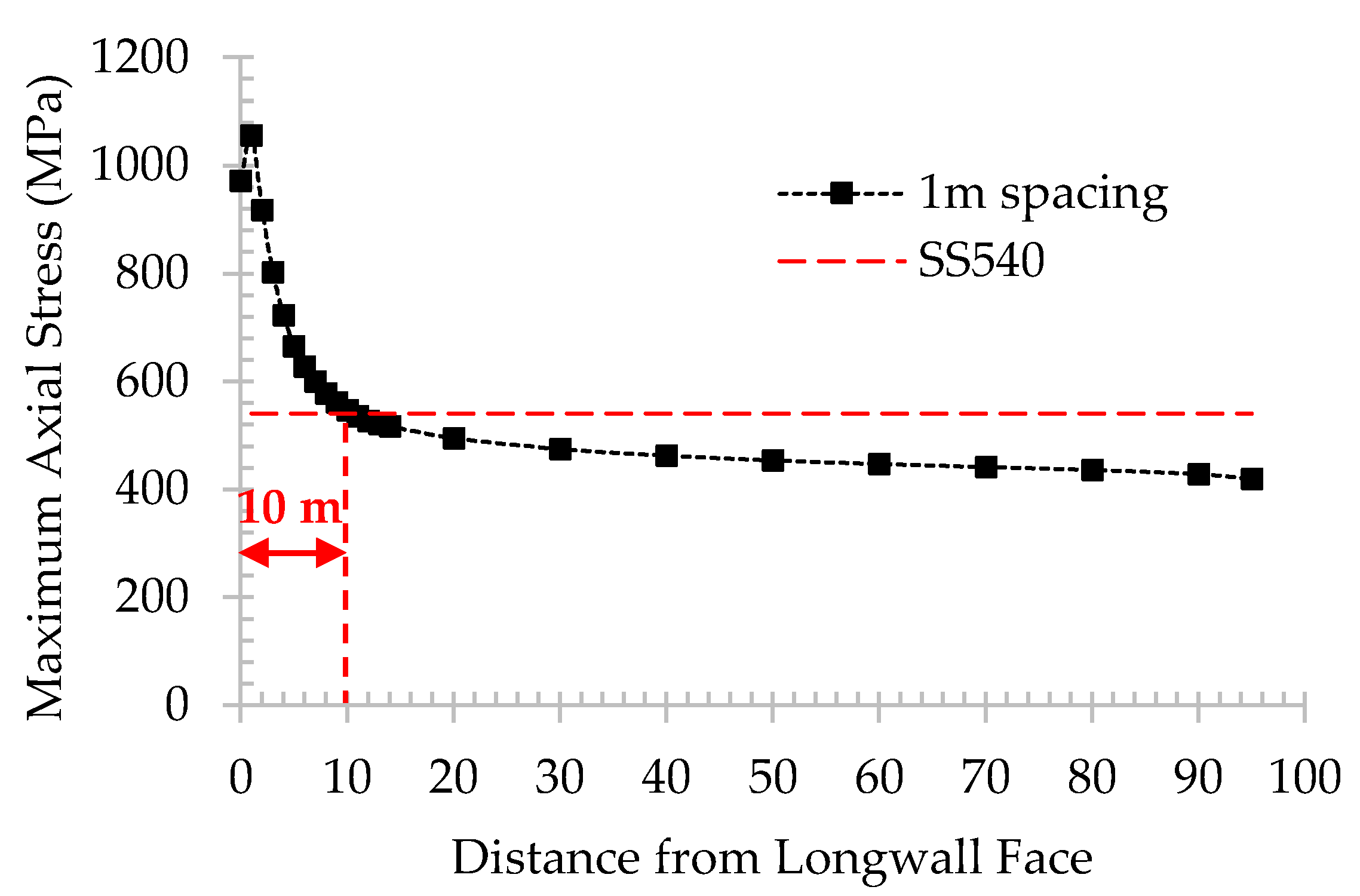
4.3.2. Maximum Axial Stress of Each Individual Support along Gate-Entry

The maximum axial stress of each individual steel arch support is a great indicator of the impact of panel extraction on the stability of gate-entry. As previously explained, in the case where support axial stress exceeds the maximum support yield strength, instability of the gate will occur. For this reason, the value of maximum axial stress of each individual steel arch used to support gate-entry is recorded from the longwall face to the direction following the mining direction. Figure 14 and Figure 15 also show the location of maximum axial stress monitoring.
Figure 18 and Figure 19 show maximum support axial stress along the gate-entry for 100 m and 150 m of depth, respectively. The results indicated that the maximum axial stress along gate-entry increased significantly for the distance close to the longwall face. The distance of over-stress can be obtained by comparing this maximum axial stress results to the yield strength of SS540. These results show that the over-stress distance of both 100 m of depth with 1 m spacing and 150 m of depth with 0.5 m spacing is approximately 10 m. It is necessary to increase the capacity of the support system by installing mobile support in this over-stress distance. The mobile support should be able to move along when the longwall face advances. Steel arch support with 1 m spacing can be used to support the gate-entry for 150 m of depth during gate excavation. However, as seen in Figure 19, the over-stress distance for 1 m spacing case exceeds 80 m in length. The longer the length, the bigger amount of mobile support that is required to maintain the stability of gate-entry. As a result, it is suggested to select a narrower 0.5 m spacing for maintaining the stability of gate-entry for 150 m of depth.

5. Conclusions

The investigation of gate-entry stability of the underground longwall mining under weak geological conditions has been carried out by numerical modeling to evaluate the most appropriate support system. The influence of remaining coal thickness has also been assessed by observing the roof sag and floor heave of the gate-entry. The gate-entry stability has been inspected at both stages of the gate development and panel extraction by monitoring the support axial stress. The summary of this research can be described as the following:
(1)
In the shallow depth where the rock is relatively weaker, the optimum thickness of 1 m of RCT can help to improve gate-entry stability by extending the overall support capacity, which is suitable for stress ratio 1.6 when adopting 1 m spacing, to withstand a higher stress ratio up to 1.9 when using the same spacing configuration.
(2)
The appropriate support configuration for 150 m of depth is 0.5 m spacing where the stress ratio is 1.6. A narrower spacing or incorporation of rock bolt or shotcrete is required in the area where the stress ratio is higher than 1.6.
(3)
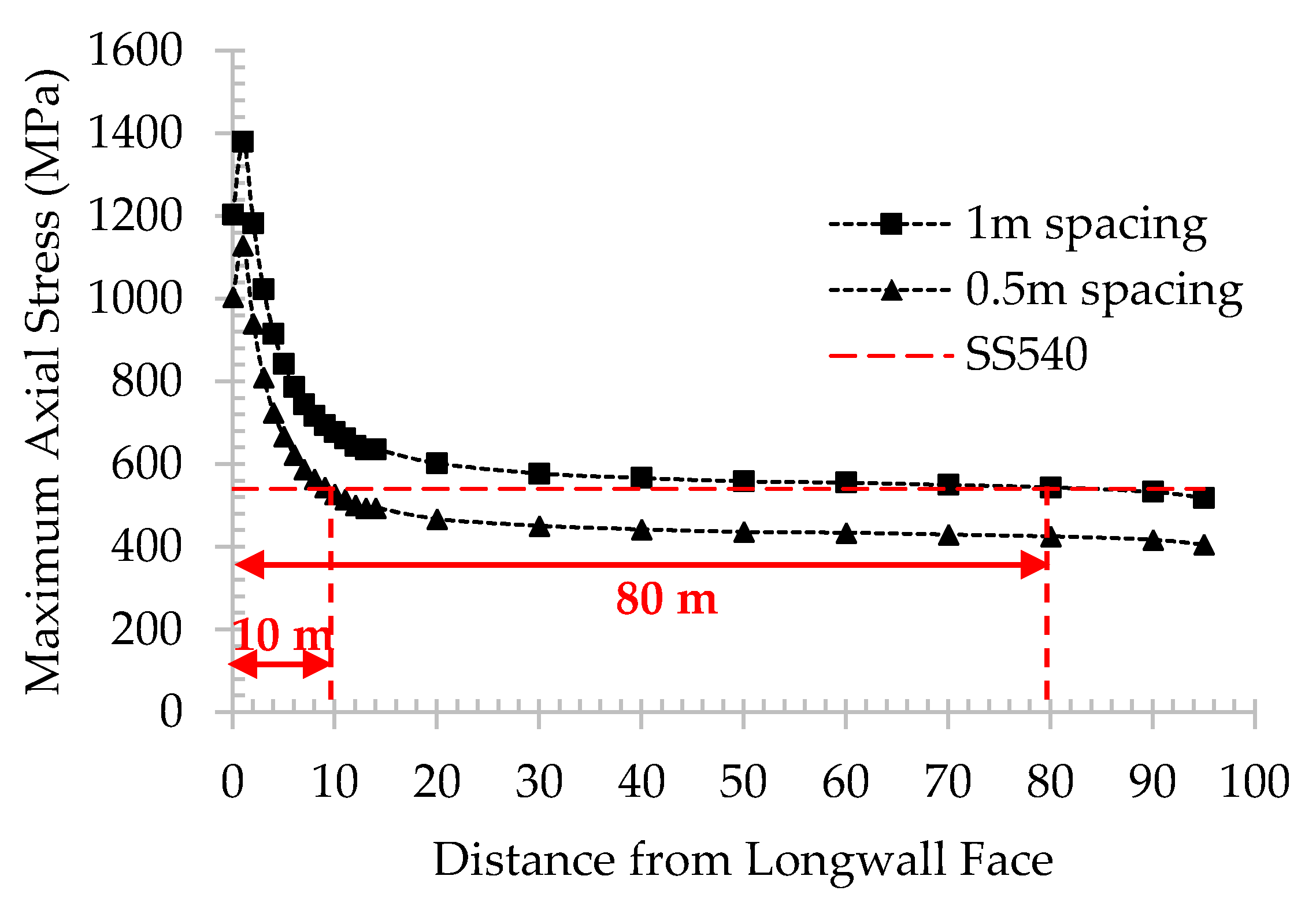
Results from the vertical stress are in line with the results of maximum support axial stress. During panel excavation, for both cases, that is, 100 m of depth with 1 m spacing and 150 m of depth with 0.5 m spacing support configuration, the unstable distance along gate-entry is approximately 10 m from the longwall face.
To sum up, a steel arch is an effective support system for gate-entry of underground longwall mining under weak geological condition. The availability of RCT helps improving the stability of the gate-entry especially in the shallow depth. The narrower support spacing is required for deeper longwall mining depth. In addition, due to the influence of panel extraction, higher stress concentration can be seen in the surrounding area of the longwall face. As a result, the end portion of gate-entry, which is connected to the longwall face, becomes unstable. To solve this problem, the installation of additional mobile support, which can be moved according to the retreat operation of the longwall face, is required in that unstable portion of gate-entry.

Author Contributions

Conceptualization, T.S. and P.M.; methodology, T.S. and P.M.; software, P.M.; validation, T.S., H.S., A.H., J.O. and P.M.; formal analysis, T.S. and P.M.; investigation, T.S. and P.M.; resources, J.O.; data curation, T.S. and P.M.; writing—original draft preparation, P.M.; writing—review and editing, T.S., H.S., A.H. and P.M.; visualization, P.M.; supervision, T.S., H.S., A.H. and J.O. All authors have read and agreed to the published version of the manuscript.

Funding

This research received no external funding.

Conflicts of Interest

The authors declare no conflict of interest.

References

  1. Sasaoka, T.; Hamanaka, A.; Shimada, H.; Matsui, K.; Lin, N.Z.; Sulistianto, B. Punch multi-slice longwall mining system for thick coal seam under weak geological conditions. J. Geol. Resour. Eng. 2015, 1, 28–36. [Google Scholar]
  2. Sasaoka, T.; Karian, T.; Hamanaka, A.; Shimada, H.; Matsui, K. Application of highwall mining system in weak geological condition. Int. J. Coal Sci. Technol. 2016, 3, 311–321. [Google Scholar] [CrossRef] [Green Version]
  3. Pongpanya, P.; Sasaoka, T.; Shimada, H.; Hamanaka, A.; Wahyudi, S. Numerical Study on Effect of Longwall Mining on Stability of Main Roadway under Weak Ground Conditions in Indonesia. J. Geol. Resour. Eng. 2017, 3, 93–104. [Google Scholar]
  4. Hoek, E.; Brown, E.T. Practical estimates of rock mass strength. Int. J. Rock Mech. Min. Sci. 1997, 34, 1165–1186. [Google Scholar] [CrossRef]
  5. Bieniawski, Z.T. Estimating the strength of rock materials. J. S. Afr. Inst. Min. Metall. 1974, 74, 312–320. [Google Scholar] [CrossRef]
  6. Guney, A.; Gul, M. Analysis of surface subsidence due to longwall mining under weak geological conditions: Turgut basin of Yatağan-Muğla (Turkey) case study. Int. J. Min. Reclam. Environ. 2019, 33, 445–461. [Google Scholar] [CrossRef]
  7. Cui, X.; Zhao, Y.; Wang, G.; Zhang, B.; Li, C. Calculation of Residual Surface Subsidence Above Abandoned Longwall Coal Mining. Sustainability 2020, 12, 1528. [Google Scholar] [CrossRef] [Green Version]
  8. Yang, R.; Zhu, Y.; Li, Y.; Li, W.; Lin, H. Coal pillar size design and surrounding rock control techniques in deep longwall entry. Arab. J. Geosci. 2020, 13, 1–14. [Google Scholar] [CrossRef]
  9. Li, Y.; Lei, M.; Wang, H.; Li, C.; Li, W.; Tao, Y.; Wang, J. Abutment pressure distribution for longwall face mining through abandoned roadways. Int. J. Min. Sci. Technol. 2019, 29, 59–64. [Google Scholar] [CrossRef]
  10. Hong-Pu, K.; Jian, L.; Yong-Zheng, W. Development of high pretensioned and intensive supporting system and its application in coal mine roadways. Procedia Earth Planet. Sci. 2009, 1, 479–485. [Google Scholar] [CrossRef] [Green Version]
  11. Jiao, Y.-Y.; Song, L.; Wang, X.-Z.; Coffi Adoko, A. Improvement of the U-shaped steel sets for supporting the roadways in loose thick coal seam. Int. J. Rock Mech. Min. Sci. 2013, 60, 19–25. [Google Scholar] [CrossRef]
  12. Meng, Q.; Han, L.; Qiao, W.; Lin, D.; Fan, J. Support technology for mine roadways in extreme weakly cemented strata and its application. Int. J. Min. Sci. Technol. 2014, 24, 157–164. [Google Scholar] [CrossRef]
  13. Phanthoudeth, P. Appropriate Design of Longwall Coal Mining System under Weak Geological Conditions in Indonesia; Kyushu University: Fukuoka, Japan, 2018. [Google Scholar]
  14. Toraño, J.; Díez, R.R.G.; Rivas Cid, J.M.; Barciella, M.M.C. FEM modeling of roadways driven in a fractured rock mass under a longwall influence. Comput. Geotech. 2002, 29, 411–431. [Google Scholar] [CrossRef]
  15. Brune, J.; Sapko, M. A modeling study on longwall tailgate ventilation. In Proceedings of the 14th United States/North American Mine Ventilation Symposium, Salt Lake City, UT, USA, 17–20 June 2012. [Google Scholar]
  16. Jiang, L.; Sainoki, A.; Mitri, H.S.; Ma, N.; Liu, H.; Hao, Z. Influence of fracture-induced weakening on coal mine gateroad stability. Int. J. Rock Mech. Min. Sci. 2016, 88, 307–317. [Google Scholar] [CrossRef]
  17. Suchowerska, A.M.; Merifield, R.S.; Carter, J.P. Vertical stress changes in multi-seam mining under supercritical longwall panels. Int. J. Rock Mech. Min. Sci. 2013, 61, 306–320. [Google Scholar] [CrossRef]
  18. Ozfirat, M.; Simsir, F.; Gonen, A. A brief comparison of longwall methods used at mining of thick coal seams. In Proceedings of the 19th International Mining Congress and Fair, Izmir, Turkey, 9–12 June 2005. [Google Scholar]
  19. Hebblewhite, B. Status and prospects of underground thick coal seam mining methods. In Proceedings of the 19th International Mining Congress and Fair, Izmir, Turkey, 9–12 June 2005. [Google Scholar]
  20. Matsui, K.; Sasaoka, T.; Shimada, H.; Furukawa, H.; Takamoto, H.; Ichinose, M. Some considerations in underground mining systems for extra thick coal seams. Coal Int. 2011, 259, 38–43. [Google Scholar]
  21. Wang, J.C.; Wang, Z.H.; Yang, S.L. Stress analysis of longwall top-coal caving face adjacent to the gob. Int. J. Min. Reclam. Environ. 2020, 34, 476–497. [Google Scholar] [CrossRef]
  22. Zarlin, N.; Sasaoka, T.; Shimada, H.; Matsui, K. Numerical study on an applicable underground mining method for soft extra-thick coal seams in Thailand. J. Eng. 2012, 4, 739–745. [Google Scholar] [CrossRef] [Green Version]
  23. Itasca_Consulting_Group. FLAC3D 5.0 Manual; Itasca Consulting Group: Minneapolis, Minnesota, 2012. [Google Scholar]
  24. Wang, J.; Yang, S.; Li, Y.; Wang, Z. A dynamic method to determine the supports capacity in longwall coal mining. Int. J. Min. Reclam. Environ. 2015, 29, 277–288. [Google Scholar] [CrossRef]
  25. Thin, I.G.T.; Pine, R.J.; Trueman, R. Numerical modelling as an aid to the determination of the stress distribution in the goaf due to longwall coal mining. Int. J. Rock Mech. Min. 1993, 30, 1403–1409. [Google Scholar] [CrossRef]
  26. Song, G.; Chugh, Y. 3D analysis of longwall face stability in thick coal seams. J. S. Afr. Inst. Min. Metall. 2018, 118, 131–142. [Google Scholar] [CrossRef]
  27. Zhao, T.; Liu, C.; Yetilmezsoy, K.; Gong, P.; Chen, D.; Yi, K. Segmental adjustment of hydraulic support setting load in hard and thick coal wall weakening: A study of numerical simulation and field measurement. J. Geophys. Eng. 2018, 15, 2481–2491. [Google Scholar] [CrossRef] [Green Version]
  28. Cheng, Y.; Wang, J.; Xie, G.; Wei, W. Three-dimensional analysis of coal barrier pillars in tailgate area adjacent to the fully mechanized top caving mining face. J. Rock Mech. Min. 2010, 47, 1372–1383. [Google Scholar] [CrossRef]
  29. Yavuz, H. An estimation method for cover pressure re-establishment distance and pressure distribution in the goaf of longwall coal mines. J. Rock Mech. Min. 2004, 41, 193–205. [Google Scholar] [CrossRef]
  30. Wang, Z.-H.; Yang, J.-H.; Meng, H. Mechanism and controlling technology of rib spalling in mining face with large cutting height passing through fault. J. China Coal Soc. 2015, 40, 42–49. [Google Scholar]
  31. Song, G.; Chugh, Y.P.; Wang, J. A numerical modelling study of longwall face stability in mining thick coal seams in China. J. Min. Miner. Eng. 2017, 8, 35–55. [Google Scholar] [CrossRef]
Figure 1. Vertical Stress Distribution during Longwall Panel Extraction.
Energies 13 04710 g001
Figure 2. Trial panel and location map of displacement monitoring devices (TT 39 and EX53).
Energies 13 04710 g002
Figure 3. Model Dimensions.
Energies 13 04710 g003
Figure 4. Modelling of steel arch for roof support.
Energies 13 04710 g004
Figure 5. Study Case of Remaining Coal Thickness.
Energies 13 04710 g005
Figure 6. Goaf modeling during panel extraction.
Energies 13 04710 g006
Figure 7. Pressure distribution for modeling shield support.
Energies 13 04710 g007
Figure 8. Comparison between telltale results and simulation results.
Energies 13 04710 g008
Figure 9. Comparison between extensometer results and simulation results.
Energies 13 04710 g009
Figure 10. Correlation between roof displacements and RCT.
Energies 13 04710 g010
Figure 11. Correlation between floor displacements and RCT.
Energies 13 04710 g011
Figure 12. Maximum support axial stress for 100 m of depth (1 m spacing).
Energies 13 04710 g012
Figure 13. Maximum support axial stress for 150 m of depth.
Energies 13 04710 g013
Figure 14. Three-dimensional (3D) schematic of the vertical stress above the mining panel at 100 m of depth.
Energies 13 04710 g014
Figure 15. 3D schematic of the vertical stress above the mining panel at 150 m of depth.
Energies 13 04710 g015
Figure 16. Vertical stress with different distance from the longwall face for 100 m of depth.
Energies 13 04710 g016
Figure 17. Vertical stress with different distance from the longwall face for 150 m of depth.
Energies 13 04710 g017
Figure 18. Maximum support axial stress along the gate-entry for 100 m of depth.
Energies 13 04710 g018
Figure 19. Maximum support axial stress along the gate-entry for 150 m of depth.
Energies 13 04710 g019
Table 1. Mechanical properties of the rock.
RockClaystone
(100 m of Depth)
Claystone
(150 m of Depth)
Coal SeamGoaf Area
Uniaxial Compressive Strength (MPa)4.846.968.16-
Density (kg/m3)2108212113801700
E (MPa)8051344130015
υ0.280.280.320.25
C (MPa)0.60.842.630.001
φ (°)37.541.845.625
σT (MPa)0.520.660.58-
Table 2. Roof support mechanical properties.
Density
(kg/m3)
E
(GPa)
υCross Area
(cm2)
Yield
(MPa)
Iy
(×10−8 m4)
Iz
(×10−8 m4)
J
(×10−8 m4)
78002000.336.5154073215422
Table 3. Lithology coefficients.
LithologyUniaxial Compressive Strength (MPa)c1c2
Strong>402.116
Medium20–404.719
Weak>206.232

