Wireless Power Hanger Pad for Portable Wireless Audio Device Power Charger Application


1
Graduate Institute of Precision Manufacturing, National Chin-Yi University of Technology, Taichung 41170, Taiwan
2
Electrical and Instrumentation Laboratory, Politeknik Negeri Bandung, Bandung 40012, Indonesia
3
Department of Refrigeration, Air Conditioning and Energy Engineering, National Chin-Yi University of Technology, Taichung 41170, Taiwan
*
Author to whom correspondence should be addressed.
Energies 2020, 13(2), 419; https://doi.org/10.3390/en13020419
Submission received: 17 December 2019
/
Revised: 31 December 2019
/
Accepted: 7 January 2020
/
Published: 15 January 2020
(This article belongs to the Special Issue Intelligent Wireless Power Transfer System and Its Application)
Abstract
:Since the portability feature has been introduced in headphone development, this device now uses a battery as the main built-in power. However, the battery has limited power capacity and a short lifetime. Battery substitution and a conventional battery charger method is an ineffective, inflexible inconvenience for enhancing the user experience. This paper presents an innovative portable audio device battery built-in charger method based on wireless power technology. The developed charging device is composed of a headphone hanger pad for the wireless headphone and a charging pad for the portable wireless audio device battery charging. Circular flat spiral air-core coil was designed and evaluated using a numerical method to obtain optimal vertical magnetic field distribution based on the proposed evaluation criteria. A coil has inner coil diameter of 25 mm, outer coil diameter of 47.8 mm, wire diameter of 0.643 mm, the pitch of 0.03 mm and a number of turns of 17 was chosen to be implemented on the transmitter coil. A magnetic induction technique was adopted in the proposed wireless power transmission module which was implemented using commercial off-the-shelf components. For experimental and validation purposes, a developed receiver module applied to the commercial wireless headphone and portable audio speaker have a built-in battery capacity at 3.7 V 300 mAh. The experimental results show that the wireless power hanger pad prototype can transfer a 5 V induction voltage at a maximum current of 1000 mA, and the power transfer efficiency is around 70%. It works at 110 kHz of operation frequency with a maximum transmission distance of about 10 mm and takes 1 h to charge fully one 3.7 V 300 mAh polymer lithium battery.
1. Introduction
Portable electronic devices are not anymore treated as deluxe products, and have largely expanded in the market over the last ten years. With their portability features in weight and size, they have become a daily necessity to people. Light in weight and smaller size, today’s electronics devices are easily handled and carried around to support daily activities from entertainment to the serious/office job. In the other side, the need for entertainment in the audiophile era has produced some meaningful developments in audio device production technology. Several key factors drive the portable audio device market growth, such as a shift in consumer favorites for enhancing an audio experience, market expansion for portable audio devices, the fast-growing music industry, increasing Internet penetration, and technologically advanced mobile technology. Two of the audio devices that come in with portable features are the earphone/headphone and audio speaker. These devices have also seen rapid growth in the market.
The global earphone and headphone market size was worth USD 10.52 billion in 2018, and is expected to achieve a compound annual growth rate (CAGR) of 5.9% over the forecast period [1]. The global audio speaker market is expected to increase at a CAGR of over 18% during 2018 to 2023, and the market size will increase by USD 42.67 billion during 2019 to 2023 [2]. In addition, technologically advanced portable audio devices and an increasing number of smartphone users can increase earphone/headphone and audio speaker market growth.
The earphone/headphone and audio speaker are very useful for music listeners, who can hear their favorite songs. Moreover, with the earphone/headphone, a music listener can hear a song without disturbing anyone else. However, the cable connection between the earphone/headphone/audio speaker and the portable audio device can be quite annoying for those who are used to listening to music. This cable stops the listener from moving freely. One of the most productive recent advances in audio technology is wireless connectivity. This technology came in order to increase consumer convenience and offer a better consumer experience. Bluetooth has only recently achieved a level where it is considered by the original equipment manufacturers (OEMs) as adequate to produce quality audio and substitute wires completely. Nevertheless, because they are cord-free, wireless earphone/headphone and audio speaker apparatus need to have built-in batteries. Only small batteries with limited capacity can be put into such a small space. As a result, their operating time is limited, because batteries eventually die. Therefore, a battery charger is needed to extend the battery life.
In the conventional method, the wireless headphone and portable audio speaker with built-in battery can be charged through an attached universal serial bus (USB) port connected with an extended USB cable to the appropriate direct current (DC) power source. This however still depended upon the core for interconnection, and is an inconvenience for the user. This method is contradictive with the portable device features today, which offer convenience, portability, safety and mobility. In addition, when the battery runs out, battery substitution is not only an ineffective option, but it also raises some very critical environmental problems related with end-of-life battery recycling [3].
Wireless power transmission (WPT) is another alternative to transfer energy from a power source over a tiny air gap without a cable for interconnection [4,5]. Since wireless power technology was introduced in mobile device applications, this method is very useful in wireless headphone and portable audio speaker battery built-in recharge applications to extend their battery life. This feature also increases device mobility and reliability [6]. This technology has the vision to become a WPT standard. The first industrial standard for mobile device inductive charging was released by the Wireless Power Consortium (WPC) [7], which is called “Qi” (pronounced “chee”) [8]. Several research works have applied WPT in portable electronic device battery charger applications [9,10,11,12,13].
Some headphone battery charger products developed by Konky and New Bee are available in the market today [14,15,16]. These products come with headphone stand/hanger and wireless charger pad for smartphone charging application. However, the headphone stand/hanger does not include wireless power functionality.
In the present world, convenience, portability, safety, mobility, compatibility, low power consumption and low cost have become very important factors in electronic device design. Therefore, a new and innovative wireless power hanger and pad is proposed in this research work to add comfort and continuous added value for the electronic device user. This paper presents a new method to charge wireless headphones and other wireless portable audio device built-in batteries adopting WPT technology. The proposed device is composed of a headphone hanger/stand pad that includes a wireless power transmitter for a wireless headphone built-in battery charger. The charger pad also includes a wireless power transmitter for the wireless portable audio devices built-in battery charger (such as a wireless portable audio speaker, or a wireless portable music player). The wireless power hanger pad prototype can transfer power at maximum 5 W wirelessly to recharge wireless headphone and audio speaker batteries.
2. Materials and Methods
2.1. Vertical Magnetic Field Distribution Numerical Analysis Method
Circular coil geometry is preferred in wireless power charger applications to maximize the Q-factor, efficiency, power handling and the related magnetic field generated by the transmitter coil. However, the analysis of magnetic field distribution generated by a circular current loop coil is still difficult in practice due to the complex magnetic coupling between the coils. In order to simplify coil structure analysis and design, it is necessary to use computational electromagnetic tools. The calculation of the electromagnetic field along the coil center axis due to the current loop is well described in the literature and electromagnetic textbooks. However, the electromagnetic field at an arbitrary point around the coil needs to be numerically calculated in order to analyze and optimize the electromagnetic field distribution generated by the coil. Thus, the maximum power transfer and efficiency of the WPT system can be achieved.
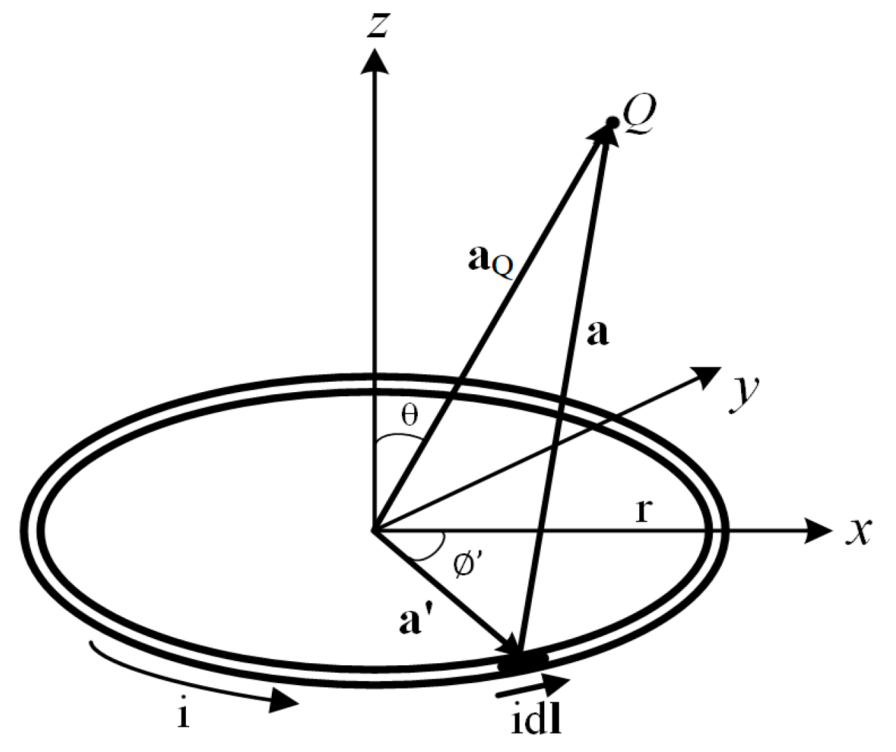
In this paper, electromagnetic field vertical distribution is generated by a single circular flat spiral air-core coil analyzed and evaluated using the off-symmetrical axis magnetic field method due to a circular current loop. The electromagnetic field distribution model derived from the Biot–Savart law and presented in Cartesian coordinates. The off-symmetrical axis magnetic field due to a circular current loop is illustrated in Figure 1.
Using the Biot–Savart law, the magnetic field contribution of the current element idl at Q can be expressed as:
where:
Thus, magnetic field at Q is:
The x-component of B can be readily shown to be zero:
with the changing of the variable r2 + y2 + z2 − 2yr sin ϕ’, the y and the z components of B can be expressed as follows:
The magnetic field from a circular coil at an arbitrary point can be obtained with a symmetrical principle. Every point (Q) in any-plane (see Figure 1) with the same z and aQ around the circular loop coil has equal Bz value. The vertical magnetic field distribution (Bz) can be calculated for any arbitrary point at x ≠ 0 using the equivalent value of Bz for arbitrary points in the yz-plane.
The numerical calculation described above was implemented in Javascript. It is used to analyze and evaluate a single circular flat spiral air-core coil design with the criteria as described in Section 3.1.
2.2. Design Overview
2.2.1. Wireless Power Hanger and Pad
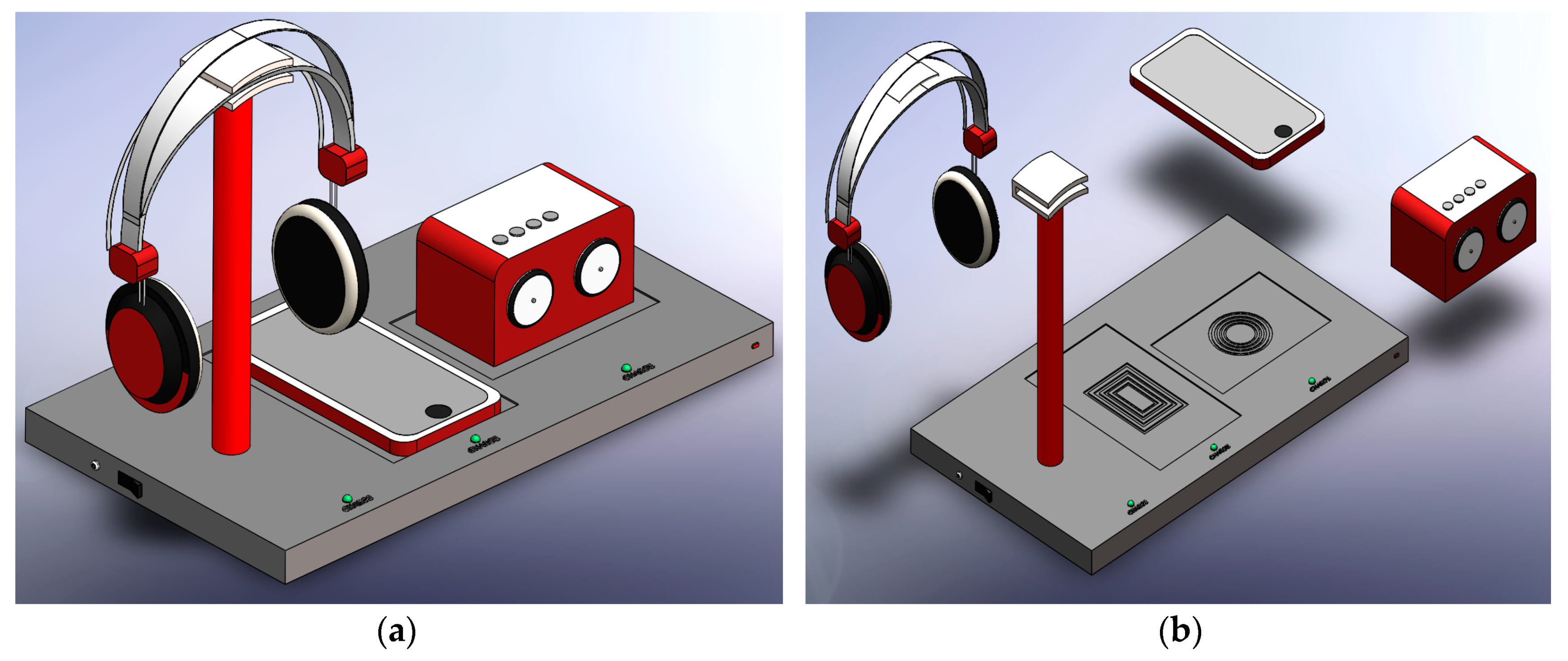
The wireless power hanger pad design is shown in Figure 2a. Compact design is pursued to achieve portability, convenience, safety, and fashionability regarding wireless power devices. The wireless power hanger pad is composed of a headphone hanger that includes a wireless power transmitter for the wireless headphone battery built-in charger, and a wireless charger pad also includes a wireless power transmitter for a wireless portable audio device battery built-in charger (such as a wireless portable audio speaker, wireless portable music player), as shown in Figure 2b.
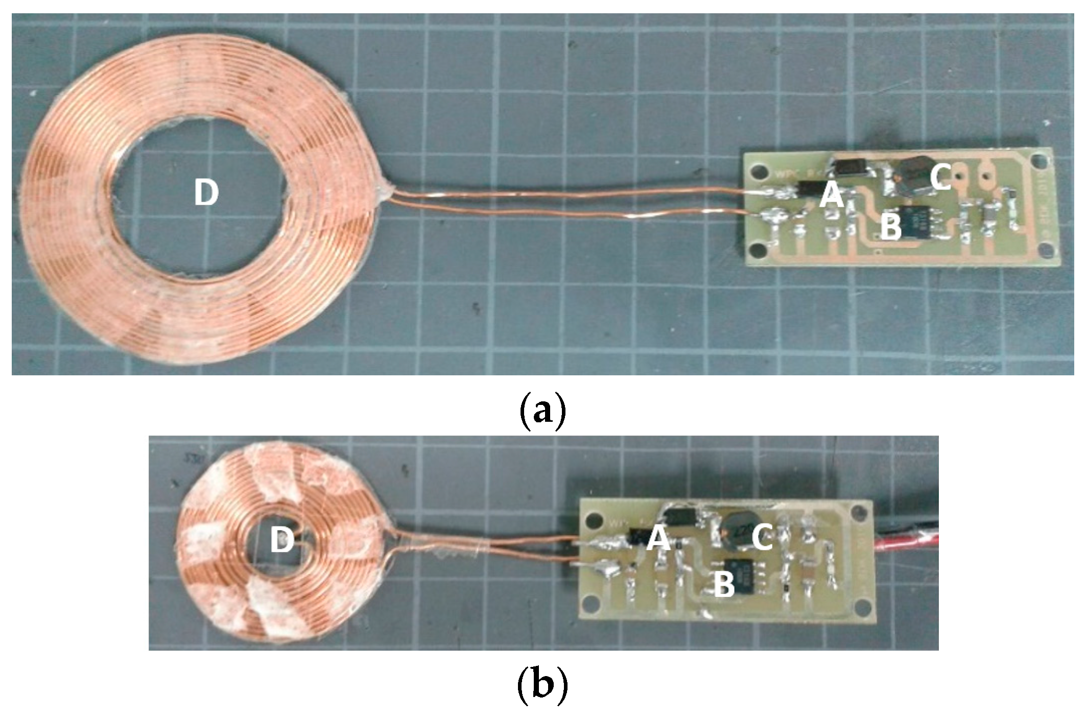
The transmitter coil in the charger pad connected with the transmitter circuit. Transmitter module which transmits the power from the DC power source wirelessly to the battery built-in of the wireless headphone and other wireless portable audio devices through the receiver module. The transmitter coil layout design on the proposed device is shown in Figure 3a.
The receiver coils and modules will be also applied on the commercial wireless headphone and portable audio speaker for experimental purposes. The receiver coils’ layout design in a wireless headphone and a portable audio speaker is shown in Figure 3b.
2.2.2. Wireless Power Transmission
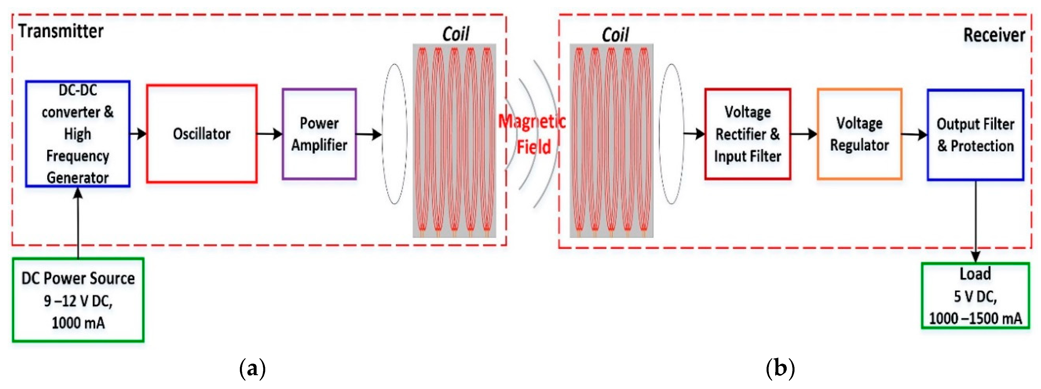
The proposed device uses a wireless transmitter module to transfer DC voltage wirelessly from a power source to a load through a wireless power receiver module. The voltage to be transmitted comes from a DC power source with 9–12 V at 1000 mA current.
Figure 4a shows the proposed wireless power transmitter. It was designed based on an inductive electromagnetic coupling and complies with international standard wireless power. A DC–DC and boost regulator converter is used to convert a low voltage (DC power source) to suitable power for high frequency and oscillator parts. A power amplifier is used in the proposed apparatus to generate a stable, high-power electromagnetic wave. The wireless power transmitter’s main part and transmitter coil together emit a stable, high-frequency electromagnetic wave.
In order to conduct the proposed device performance test, a wireless power receiver apparatus was also developed to be installed in the wireless headphone and portable audio speaker. A wireless power receiver apparatus absorbs electromagnetic waves from the wireless power transmitter apparatus through a receiver coil. The absorbed electromagnetic waves are converted into a stable output voltage at 5 V and a maximum current up to 1500 mA to charge wireless headphone and portable audio speaker batteries. Figure 4b shows the wireless power receiver apparatus block diagram. The receiver apparatus’s main part includes a rectifier, filter and voltage regulator.
3. Design and Results
3.1. Coil Design
In particular, the magnetic fields are critical in wireless power charging system coil design. The magnetic field distribution gives a significant effect on WPT system power transfer performance. Thus, the coil design must be the first step in wireless power charging system design. Some of the aspects to be considered include the coil geometry, type and size of the wire used, the number of turns, and the magnetic field generated by the coils.
In this work, a circular, flat spiral air-core was chosen to be applied in the proposed device WPT system. This geometry has been widely used in wireless power transfer applications to improve power transfer performance and misalignment tolerance compared to other coil geometries [18,19]. Several coil structures with different coil parameters were numerically analyzed using the method presented in [17] to obtain the proper vertical magnetic field (Bz) distribution and transmitting area for the proposed device. The evaluated coil geometry is a circular flat spiral air-core coil as shown in Figure 5, which has parameters as shown in Table 1.
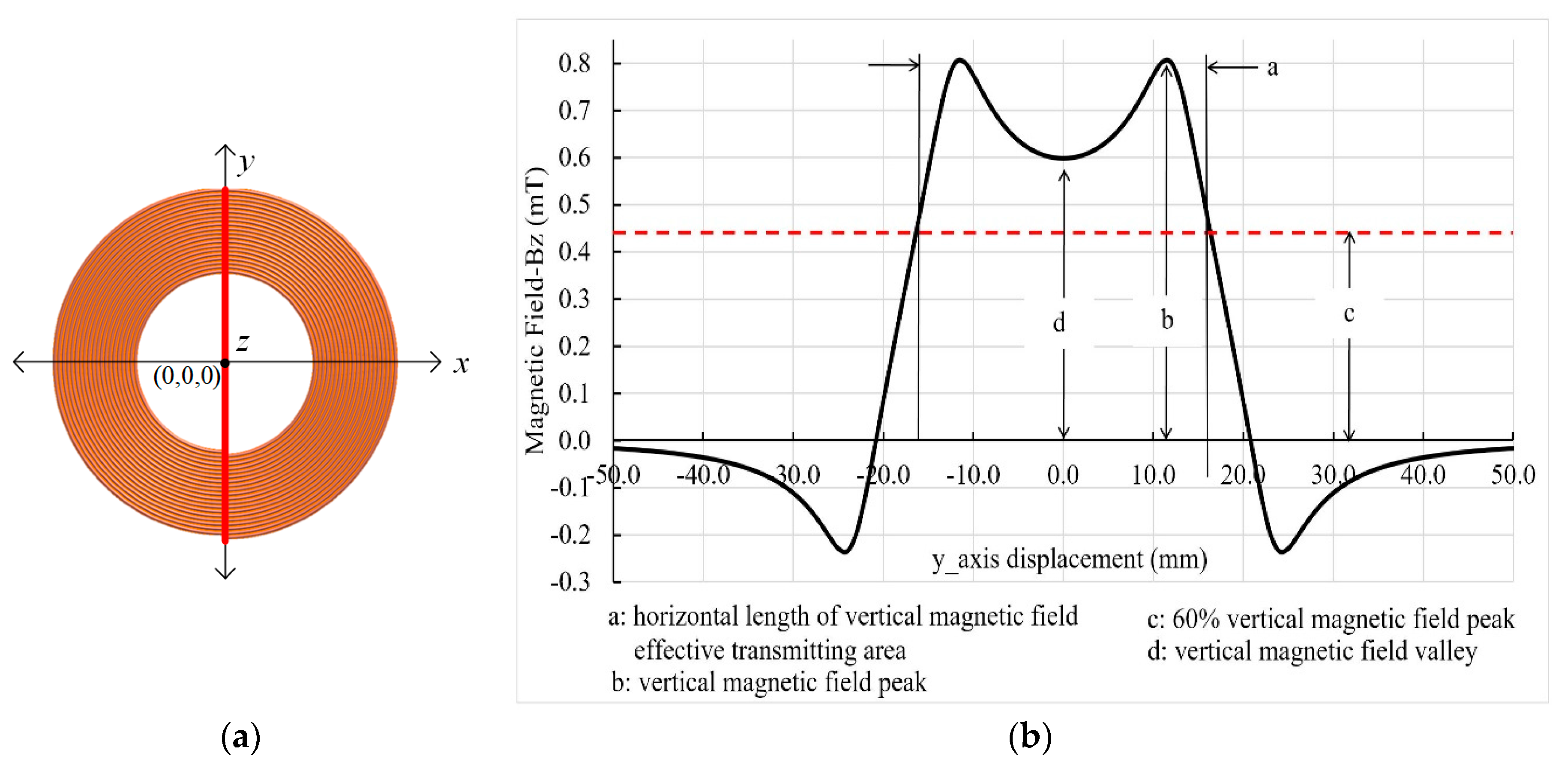
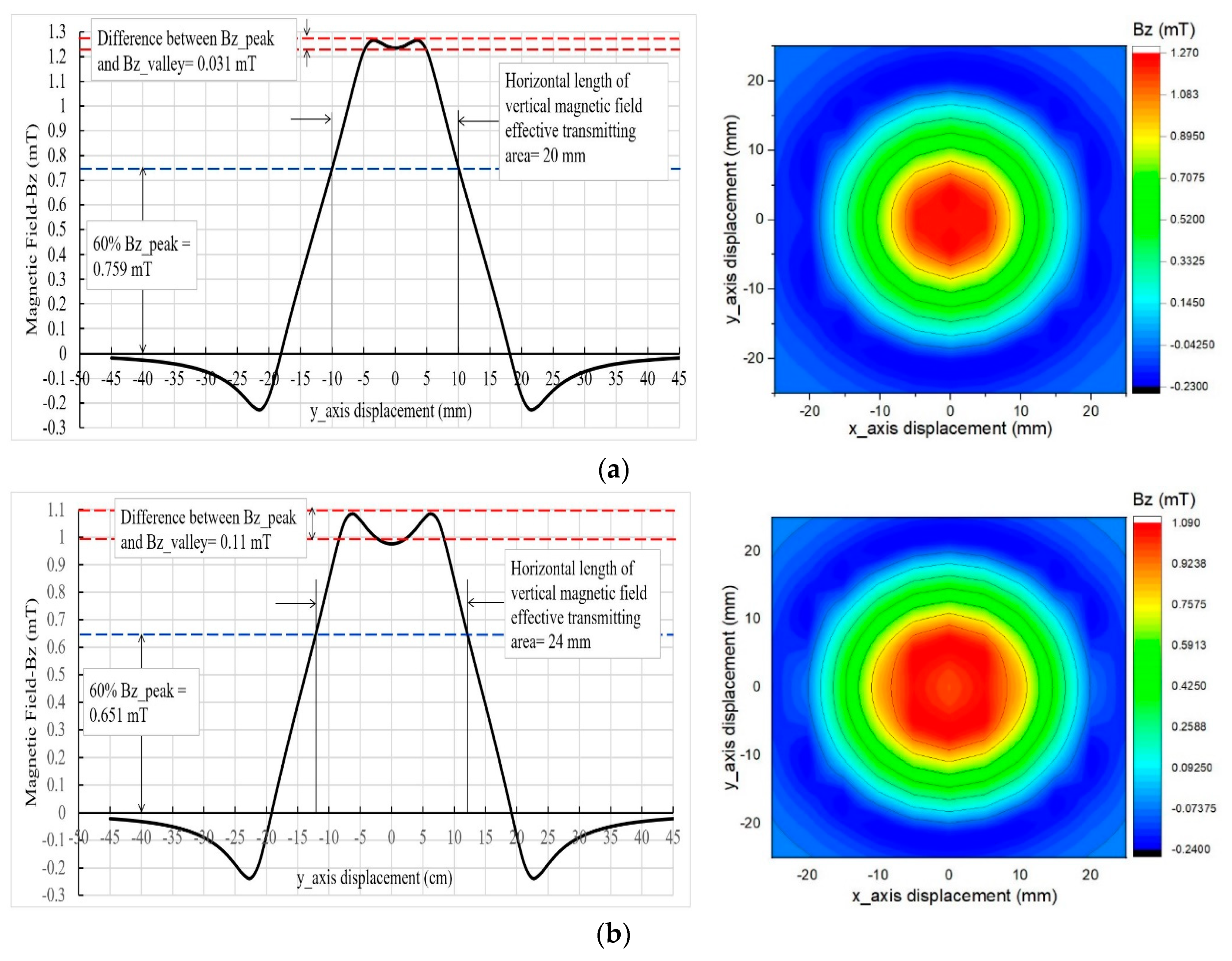
The evaluated coils analyzed and evaluated along the y-axis with the evaluation criteria that the vertical magnetic field distribution valley (Bz valley) is not less than 60% of the vertical magnetic field peak/max (Bz peak/max), the difference between the Bz peak/max and Bz valley is relatively small, and the magnetic field effective transmitting area is as wide as possible. The evaluation path and vertical magnetic field distribution characteristic curve along the y-axis are both shown in Figure 6.
As shown in Figure 7, among the evaluated coils, the coil with Di = 10 mm has the highest Bz peak/max (1.266 mT) with Bz valley = 1.235 mT, 60% Bz peak/max = 0.759 mT, and the horizontal length of the vertical magnetic field effective transmitting area = 20 mm (the detail of Bz distribution characteristic curve is shown in Figure 8a). While the coil with Di = 30 mm has the lowest Bz peak/max (0.737 mT), with the Bz valley = 0.501 mT, 60% Bz peak/max = 0.442 mT, and the horizontal length of the vertical magnetic field effective transmitting area = 36 mm (the detail of Bz distribution characteristic curve is shown in Figure 8e).
The Bz distribution characteristic curve and the magnetic field effective coverage area detail for every evaluated coil are shown in Figure 8.
From the magnetic field analysis and evaluation result, the coil with coil parameters Di = 25 mm, Do = 47.8 mm, N = 17, P = 0.03 mm and W = 0.643 mm were chosen to be applied in the proposed device WPT system. This coil was chosen considering all evaluation criteria as described above. This coil has a Bz valley value (0.598 mT) higher than its 60% vertical magnetic field peak/max value (0.482 mT), as shown in Figure 8d. Its horizontal length of the vertical magnetic field effective transmitting area (34 mm) is also longer than the horizontal length of the vertical magnetic field effective transmitting area of coils with Di = 10 mm, Di = 15 mm and Di = 20 mm.
The coil with Di = 30 mm has the longest horizontal length of the vertical magnetic field effective transmitting area (36 mm) among other coils (coils with Di = 10 mm, Di = 15 mm, Di = 20 mm, Di = 25 mm). However, this coil has a large difference between the Bz peak/max and Bz valley (0.236 mT). It has also vertical magnetic field peak/max (0.737 mT) smaller than the vertical magnetic field peak/max of coil with Di = 25 mm, as shown in Figure 8d,e. Therefore, this coil was not chosen in the proposed WPT system implementation.
The circular flat spiral air-core coil self-inductance can be described by Harold A. Wheeler’s approximations formula [20,21]:
where L is the inductance in microhenries (µH), N is the total number of turns, W is the wire diameter in millimeters (mm), P is the turn spacing in millimeters, and Di is the coil’s inner diameter in millimeters.
According to the calculations using Equation (13), in the case of a single circular flat spiral air-core coil having 17 and 1 number of turns and layers, respectively, if Di is 25 mm, P is 0.03 mm, and W is 0.643 mm, then L, Do, and the wire length (Wl) are 13.9 µH, 47.89 mm, and 1919.7 mm, respectively. An AWG 22 wire was chosen because of its small diameter (0.643 mm diameter and 0.0646 mm insulating layer) and the fact that it can be used for carrying a maximum current of 7 A. However, due to manual manufacturing, the transmitter coil is characterized by L is 13.7 µH and Do is 48.36 mm. The transmitter coil’s geometry is shown in Figure 9a.
The receiver coil was designed with the same diameter and parameters as well as the transmitter coil to maximize the coupling efficiency. In the implementation, the receiver coil is characterized by 14.02 µH of L, Do is 48.50 mm and Wl is 1925 mm because of manual manufacturing. The receiver coil geometry is shown in Figure 9b. A small receiver coil geometry was also designed to achieve compatibility with a modified wireless headphone. This coil is characterized by 13.89 µH of L, having 26 and 2 number of turns and layers, respectively. Di is 10 mm, and Do is 28.5 mm as shown in Figure 10.
3.2. Wireless Power Transmitter Apparatus
The wireless power transmitter module is composed of three main parts, as described in Figure 11. Part A is a high frequency generator made up of a radio frequency power supply chip (XKT–412), R1 = 8.2 kΩ, R2 = R3 = 47 kΩ, R4 = 10 kΩ and C1 = 1 nF/50 V. This chip automatically generates a square wave (PTS pin) with a frequency of around 70 kHz. It can produce a voltage of 7 V and a maximum current of 1 Ampere.
Part B is a power amplifier made up of a wireless power transmitter chip (T5336) and C2 = 47 µF/16 V. It can provide a controllable high-frequency power output (OSS) with a voltage gain four times IN (PTS). The OSS voltage is around 32 V. The voltage difference between the DC voltage (VCC) and the T5336 output (OUT) controls the operating frequency/oscillator (part C); then, the transmitter coil emits a stable high-frequency electromagnetic wave.
Part C is an oscillator. It is made up of an LC tank together with a transmitter coil (L1 = 13.9 µH), and C3 = C4 = C5 = C6 = 39 nF/50 V. A parallel capacitor is selected to achieve an operating frequency of around 110 kHz. This operating frequency was chosen to be compliant with the WPC standard operating frequency between 100–205 kHz [7,8]. The operating frequency can be obtained by Equation (14):
where C is the capacitance in farads (F), L is the coil inductance in henrys (H), and f is the oscillation frequency in hertz (Hz).
The circuitry described above was implemented on the final wireless power transmitter apparatus PCB (50 mm × 20 mm) prototype. The integrated wireless power transmitter with the transmitter coil is shown in Figure 12.
3.3. Wireless Power Receiver Apparatus
Figure 13 shows the wireless power receiver parts. The electromagnetic wave transmitted from the wireless power transmitter apparatus is a high-frequency oscillation wave. It is received by a receiver coil (L1 = 13.9 µH) and converted into DC voltage using a rectifier and filter circuit. Part A is a voltage rectifier and input filter. It is made up of C1 = 27 nF/25 V and D1 = SS34 as a voltage rectifier, and C2 = 10 µF/25 V, R1 = 10 kΩ and R2 = 6.2 kΩ as an input filter. The apparatus core is a wireless power receiver chip (T3168) and voltage adjustment R3 = 6.2 kΩ and R4 = 2 kΩ (Part B). The T3168 chip has a simple peripheral circuit. It not only has the electromagnetic energy receiving function but also DC–DC voltage reducing and DC–DC voltage stabilizing.
By electromagnetic induction, the T3168 chip and Part A receive the electromagnetic wave, step down the voltage, and generate a corresponding stable charging voltage at 5 V and a maximum current up to 1500 mA. Part C is an output filter and protection. It is made up of D2 = SS34 and L2 = 22 µH as feedback protection, and C3 = 10 µF/16 Volt as an output filter.
The integrated receiver coil and wireless power receiver PCB (45 mm × 20 mm) prototype according to the circuit design described above is shown in Figure 14.
4. Testing and Prototyping
4.1. The Performance Characteristic of Developed WPT System
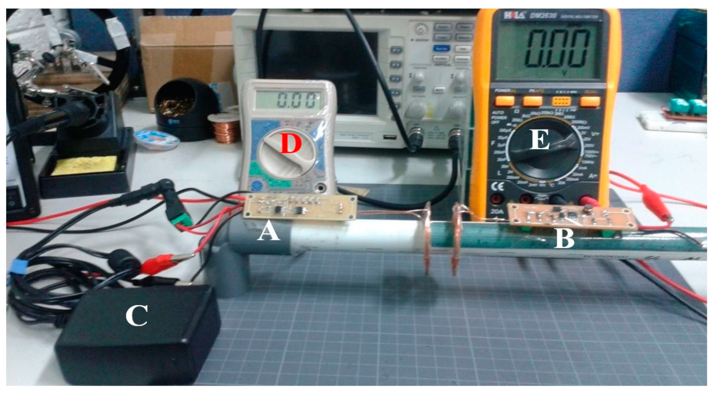
An experiment was conducted to measure the performance characteristic of the developed WPT system. Figure 15 shows the experimental setup comprises a 9–12 V, 1000 mA DC power supply, wireless power transmitter and wireless power receiver apparatuses itself, two multimeters and an oscilloscope. The wireless power transmitter and wireless power receiver apparatuses are put in parallel to each other at a vertical alignment in between 20 mm of distance. The DC power supply provides power for the developed wireless power transmitter apparatus and sends it wirelessly to a load (resistor or cell phone) through the developed wireless power receiver apparatus. The multimeters are connected to the developed wireless power transmitter apparatus input terminal and the developed wireless power receiver apparatus output terminal to measure power delivery. The electromagnetic wave from the developed wireless power transmitter apparatus is captured and measured using a Digital Storage Oscilloscope (GwInstek MDO-2072EX 70 MHz 1GS/s, New Taipei City, Taiwan).
During the experiment, an open load circuit, short circuit, and a closed circuit at the wireless power receiver apparatus terminal output site were configured. In this experiment, a 4 Ω resistor was used as the load. The distance between the transmitter and receiver coils was increased by the 5 mm step from 0 to 20 mm. The current, voltage and power at the wireless power transmitter apparatus terminal input and the wireless power receiver apparatus terminal output were measured, respectively. The power delivery efficiency can also be obtained as an evaluation result.
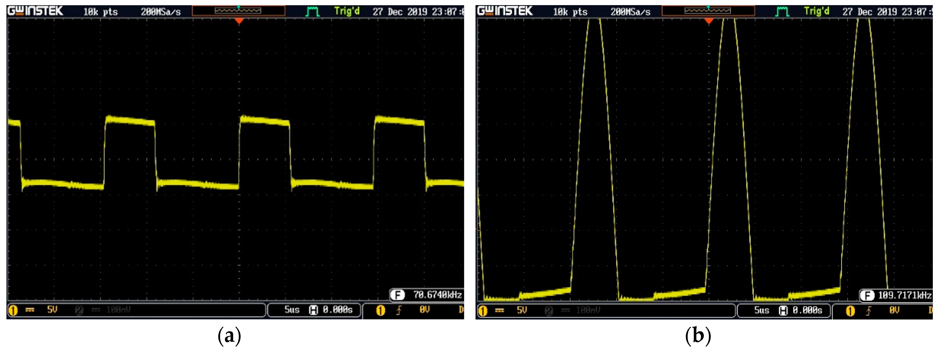
The developed wireless power transmitter apparatus operates at a 110 kHz operating frequency. Figure 16 shows the experimental waveforms generated by the radio frequency power supply chip and the wireless power transmitter chip in conjunction with an oscillator part. The radio frequency power supply chip generates a square wave with the output voltage of 7 V and an output frequency of about 70 kHz. The measured waveform results are shown in Figure 16a. Figure 16b shows the T5336 chip and oscillator wave output which is controlled by the radio frequency power supply chip. The waveform is a sinusoidal wave with an amplitude of 32 V and frequency (operating frequency) of about 110 kHz. This operating frequency is in compliance with the WPC standard.
Figure 17 shows the developed wireless power transmitter apparatus’s characteristic measured results. The developed wireless power transmitter apparatus characteristics have been measured and depend on the wireless power receiver output, the load, and the distance between the transmitter and receiver coils. The maximum voltage, current and power on the wireless power receiver output are obtained at the smallest distance (tightly coupled) between the transmitter and receiver coils, whatever the load types (open circuit, short circuit, 4 Ω).
Those decrease gradually with the increase in the distance between the transmitter and receiver coils because of the high transmission coupling loss, as shown in Figure 17a–c.
4.2. System Integration
The proposed device prototype was implemented according to the proposed design described in Section 2.2. The final wireless power hanger/stand pad prototype is shown in Figure 18a. The coils and WPT modules applied to the developed device were put into a fit casing made using acrylic material. The base charger pad size is 24 × 16 × 2 cm, with two transmitter coils for portable electronic device wireless power charger functionality, while the dimension of the headphone hanger is 2 × 3 × 16 cm with a wireless power charger pad on the top.
The complete wireless power charging configuration is shown in Figure 18b. A wireless headphone included with the developed wireless power receiver module is put on the headphone hanger charger pad, while the wireless portable electronic device (cell phone, portable audio speaker) is put on the charging pad base.
The developed receiver coils and modules were also applied to the commercial wireless headphone and portable wireless audio speaker as shown in Figure 19 for charging functionality testing.
The developed receiver module output was extended with a cable, it has a micro USB terminal and is connected to an attached USB port on the wireless headphone, as shown in Figure 19a. While the developed receiver module installation on a commercial portable wireless audio speaker is shown in Figure 19b.
The developed receiver module output terminal connected directly to the battery built-in inside the portable wireless audio speaker. The specifications of wireless headphone and portable audio speaker are shown in Table 2. Both devices have a Bluetooth V4.1 interface with maximum transmission range up to 10 m (without obstacle) to communicate with music player device.
4.3. Charging Functionality Testing
This testing was done to verify the charging functionality and performance of the developed device. The charging targets were the wireless headphone, audio speaker and smartphone with built-in batteries. The battery capacities of the wireless headphone and audio speaker are 3.7 V and 300 mAh, respectively, while the battery capacity of the cell phone is 3.8 V and 5.7 Wh, respectively. The charging functionality testing result is shown in Figure 20. The charging indicators on the devices under recharging show that the devices are in the charging process. Every transmitter module on the wireless power hanger pad prototype can transfer wirelessly a 5 V induction voltage at maximum current 1000 mA to the headphone, audio speaker and smartphone with built-in batteries.
The charging curve was experimentally obtained by measuring the wireless headphone battery voltage being charged, as shown in Figure 21. A 3.7 V 300 mAh Polymer Lithium rechargeable battery was used to perform the charging curve experiments. The measurement and recharging process stopped after 12 min of the charging process because the battery voltage remained constant. The charging process can still be continued to increase the battery power capacity and it takes 1 h charging time to achieve full battery power capacity.
5. Conclusions
The developed charger device prototype enhanced the user’s experience in order to extend the modified wireless headphone and portable audio device’s built-in battery life without any core for interconnection with the power source. The experiment and testing results show that the developed device can work according to design to provide proper battery charging power for modified wireless headphone and portable audio devices. It can transfer wirelessly the 5 V induction voltage at a maximum current of 1000 mA from 5–9 V 1000 mA power source to the device under recharging. The proposed device complies with an international standard for operational compatibility, working at a 110 kHz operating frequency and achieving maximum power transfer distance at 10 mm. Charging testing shows that the prototype can charge fully a 3.7 V 300 mAh Polymer Lithium rechargeable battery in around 1 h.
Author Contributions
Conceptualization, Y.-D.K.; methodology, C.B.D.K. and Y.-D.K.; formal analysis, C.B.D.K. and W.-J.L.; investigation, C.B.D.K., Y.-D.K. and W.-J.L.; supervision, Y.-D.K.; resources, Y.-D.K.; writing—original draft preparation, C.B.D.K.; writing—review and editing, W.-J.L. and Y.-D.K. All authors have read and agreed to the published version of the manuscript.
Funding
This research was funded by and the Ministry of Science and Technology of Taiwan (MOST 107-3113-E-008-003).
Acknowledgments
The authors thank the Ministry of Science and Technology of Taiwan.
Conflicts of Interest
The authors declare no conflict of interest.
References
- Earphones Headphones Market Size, Share Trends Analysis Report by Product. Available online: https://www.grandviewresearch.com/industry-analysis/earphone-and-headphone-market (accessed on 30 October 2019).
- Global Speakers Market 2019–2023. Available online: https://www.technavio.com/report/global-speakers-market-industry-analysis (accessed on 1 November 2019).
- Kuncoro, C.B.D.; Sung, M.-F.; Kuan, Y.-D. Battery Charger Prototype Design for Tire Pressure Sensor Battery Recharging. Sensors 2019, 19, 124. [Google Scholar] [CrossRef] [PubMed] [Green Version]
- Costanzo, A.; Dionigi, M.; Masotti, D.; Mongiardo, M.; Monti, G.; Tarricone, L.; Sorrentino, R. Electromagnetic Energy Harvesting and Wireless Power Transmission: A Unified Approach. Proc. IEEE 2014, 102, 1692–1711. [Google Scholar] [CrossRef]
- Garnica, J.; Chinga, R.A.; Lin, J. Wireless Power Transmission: From Far Field to Near Field. Proc. IEEE 2013, 101, 1321–1331. [Google Scholar] [CrossRef]
- Barman, S.D.; Reza, A.W.; Kumar, N.; Karim, M.E.; Munir, A.B. Wireless Powering by Magnetic Resonant Coupling: Recent Trends in Wireless Power Transfer System and its Applications. RSER 2015 2015, 51, 1525–1552. [Google Scholar] [CrossRef]
- System Description Wireless Power Transfer, Volume I: Low Power, Part 1: Interface Definition, Version 1.0.2; Wireless Power Consortium: Piscataway, NJ, USA, 2011.
- Wireless Power Consortium. Available online: http://www.wirelesspowerconsortium.com/index.html (accessed on 8 September 2019).
- Lu, Y.; Ma, D.B. Wireless Power Transfer System Architectures for Portable or Implantable Applications. Energies 2016, 9, 1087. [Google Scholar] [CrossRef]
- Roshan, Y.M.; Park, E.J. Design approach for a wireless power transfer system for wristband wearable devices. IET Power Electron. 2017, 10, 931–937. [Google Scholar] [CrossRef]
- Eberhard Waffenschmidt. Wireless Power for Mobile Devices, VDE-Kongress 2010; Eberhard Waffenschmidt: Leipzig, Germany, 2010. [Google Scholar]
- Hui, R.; Ho, W. A new generation of universal contactless battery charging platform for portable consumer electronic equipment. In Proceedings of the 35th IEEE Power Electronics Specialist’s Conference, Aachen, Germany, 20–25 June 2004. [Google Scholar]
- Cao, G.; Kim, H.J.; Choi, D.; Lim, J.; Cheng, P.; Bae, S. Design of a Wireless Power Transmission System for Portable Electronic Equipment. In Proceedings of the 17th International Conference on Electrical Machines and Systems (ICEMS), Hangzhou, China, 22–25 October 2014. [Google Scholar]
- KONKY Wireless Charging Headphone Stand. Available online: https://www.amazon.com/KONKY-Wireless-Charging-Headphone-Compatible/dp/B07H96TG49 (accessed on 5 November 2019).
- Wireless Charging with Headphone Stand New Bee. Available online: https://www.amazon.co.uk/Headphone-Wireless-New-Bee-Indicator-Black-Charger/dp/B07BZP6TG9 (accessed on 5 November 2019).
- Wireless Charger Built-in Wireless Charging Base. Available online: https://www.amazon.com/Wireless-Charging-Headphone-New-Indicator/dp/B06X15HLD9 (accessed on 5 November 2019).
- Luo, W.-J.; Kuncoro, C.B.; Pratikto, D.; Kuan, Y.-D. Single-Layer Transmitter Array Coil Pattern Evaluation toward a Uniform Vertical Magnetic Field Distribution. Energies 2019, 12, 4157. [Google Scholar] [CrossRef] [Green Version]
- Fernandez, C.; Garcia, O.; Prieto, R.; Cobos, J.A.; Gabriels, S.; Borght, G. Van Der Design issues of a coreless transformer for a contactless application. In Proceedings of the Seventeenth Annual IEEE Applied Power Electronics Conference and Exposition, Dallas, TX, USA, 10–14 March 2002. [Google Scholar]
- Mitcheson, P.D.; Green, T.C.; Yeatman, E.M.; Holmes, A.S. Architectures for Vibration-Driven Micropower Generators. J. Microelectromechanical Syst. 2004, 13, 429–440. [Google Scholar] [CrossRef] [Green Version]
- Mohan, S.S.; Hershenson, M.; Boyd, S.P.; Lee, T.H. Simple Accurate Expressions for Planar Spiral Inductances. IEEE J. Solid-State Circuits 1999, 34, 1419–1424. [Google Scholar] [CrossRef] [Green Version]
- Wheeler, H.A. Simple Inductance Formulas for Radio Coils. Proc. Inst. Radio Eng. 1928, 16, 1398–1400. [Google Scholar] [CrossRef]
Figure 1.
The symmetry axis magnetic field due to a circular current loop [17].
Figure 1.
The symmetry axis magnetic field due to a circular current loop [17].

Figure 2.
Conceptual design: (a) proposed architecture; (b) proposed wireless hanger and pad design.
Figure 2.
Conceptual design: (a) proposed architecture; (b) proposed wireless hanger and pad design.

Figure 3.
Coil layouts: (a) transmitter coil; (b) receiver coil.

Figure 4.
Block diagram Wireless power transmission (WPT) apparatus: (a) transmitter; (b) receiver.

Figure 5.
Circular, flat spiral, air-core single coil geometry.

Figure 6.
(a) Evaluation path along the y-axis, (b) vertical magnetic field distribution along the y-axis.
Figure 6.
(a) Evaluation path along the y-axis, (b) vertical magnetic field distribution along the y-axis.

Figure 7.
The vertical magnetic field distribution characteristic curve of evaluated coils along the y-axis.
Figure 7.
The vertical magnetic field distribution characteristic curve of evaluated coils along the y-axis.

Figure 8.
Vertical magnetic field distribution characteristic curve along the y-axis, and overall vertical magnetic field distribution with magnetic field effective transmitting area: (a) Coil with Di = 10 mm; (b) Coil with Di = 15 mm; (c) Coil with Di = 20 mm; (d) Coil with Di = 25 mm; (e) Coil with Di = 30 mm.


Figure 9.
Coil: (a) transmitter; (b) receiver.

Figure 10.
The Single coil evaluation path.

Figure 11.
The wireless power transmitter apparatus core. Part A is a DC–DC converter and high frequency generator, part B is a power amplifier, part C is an oscillator, and part D is transmitter coil. (Where DC stands for direct current).
Figure 11.
The wireless power transmitter apparatus core. Part A is a DC–DC converter and high frequency generator, part B is a power amplifier, part C is an oscillator, and part D is transmitter coil. (Where DC stands for direct current).

Figure 12.
Wireless power transmitter apparatus prototype. Part A is a DC–DC converter and a high frequency generator, part B is a power amplifier, part C is an oscillator and part D is a transmitter coil.
Figure 12.
Wireless power transmitter apparatus prototype. Part A is a DC–DC converter and a high frequency generator, part B is a power amplifier, part C is an oscillator and part D is a transmitter coil.

Figure 13.
The wireless power receiver apparatus core. Part A is a voltage rectifier and input filter, part B is a voltage regulator, part C is an output filter and protection, and part D is receiver coil.
Figure 13.
The wireless power receiver apparatus core. Part A is a voltage rectifier and input filter, part B is a voltage regulator, part C is an output filter and protection, and part D is receiver coil.

Figure 14.
Wireless power receiver prototype: (a) coil with Di = 25 mm; (b) coil with Di = 10 mm. Part A is a voltage rectifier and input filter, part B is a voltage regulator, part C is an output filter and protection, and part D is a receiver coil.
Figure 14.
Wireless power receiver prototype: (a) coil with Di = 25 mm; (b) coil with Di = 10 mm. Part A is a voltage rectifier and input filter, part B is a voltage regulator, part C is an output filter and protection, and part D is a receiver coil.

Figure 15.
Experimental setup. A is the wireless power transmitter apparatus, B is the wireless power receiver apparatus, C is the direct current (DC) power source, D and E are the multimeter.
Figure 15.
Experimental setup. A is the wireless power transmitter apparatus, B is the wireless power receiver apparatus, C is the direct current (DC) power source, D and E are the multimeter.

Figure 16.
Measured waveform using oscilloscope: (a) the radio frequency power supply chip waveform; (b) operating frequency waveform.
Figure 16.
Measured waveform using oscilloscope: (a) the radio frequency power supply chip waveform; (b) operating frequency waveform.

Figure 17.
The developed wireless power transmitter characteristics: (a) the output voltage characteristics; (b) the output current characteristics; (c) the output power characteristics; (d) the efficiency characteristics.
Figure 17.
The developed wireless power transmitter characteristics: (a) the output voltage characteristics; (b) the output current characteristics; (c) the output power characteristics; (d) the efficiency characteristics.

Figure 18.
(a) Wireless power hanger and pad prototype (part A is THE hanger charger pad and part B is the charger pad); (b) Portable electronic devices charging configuration on the developed device prototype (part A is wireless headphone, part B is wireless audio speaker, and part C is cell phone).

Figure 19.
The developed wireless receiver module installation: (a) on the wireless headphone (part A is receiver module and part B is receiver coil); (b) on wireless portable audio speaker (part A is receiver module and part B is receiver coil).
Figure 19.
The developed wireless receiver module installation: (a) on the wireless headphone (part A is receiver module and part B is receiver coil); (b) on wireless portable audio speaker (part A is receiver module and part B is receiver coil).

Figure 20.
Built-in battery charging testing: (a) charging testing on wireless headphone; (b) charging testing on smartphone; (c) charging testing on wireless portable audio speaker.
Figure 20.
Built-in battery charging testing: (a) charging testing on wireless headphone; (b) charging testing on smartphone; (c) charging testing on wireless portable audio speaker.

Figure 21.
A typical charging curve wireless headphone battery.


Table 1.
Coil parameters.
| Parameter | Coil_1 | Coil_2 | Coil_3 | Coil_4 | Coil_5 |
|---|---|---|---|---|---|
| Number of turns (N) | 24 | 22 | 19 | 17 | 15 |
| Inner diameter (Di) (mm) | 10 | 15 | 20 | 25 | 30 |
| Outer diameter (Do) (mm) | 42.3 | 43.9 | 45.5 | 47.8 | 50.8 |
| Pitch (P) (mm) | 0.03 | 0.03 | 0.03 | 0.03 | 0.03 |
| Wire diameter (W) (mm) | 0.643 | 0.643 | 0.643 | 0.643 | 0.643 |
Table 2.
Product specification.
| Parameter | Headphone | Audio Speaker |
|---|---|---|
| Output power | 300 mW | 3 W |
| Operating Voltage | 5 VDC | 5 VDC |
| Signal to noise ratio | 85 dB | 80 db |
| Battery type | Rechargeable Polymer Lithium 300 mAh | Rechargeable Polymer Lithium 300 mAh |
| Weight | 165 g | 163 g |
| Size | 178 |
© 2020 by the authors. Licensee MDPI, Basel, Switzerland. This article is an open access article distributed under the terms and conditions of the Creative Commons Attribution (CC BY) license (http://creativecommons.org/licenses/by/4.0/).
Share and Cite
MDPI and ACS Style
Luo, W.-J.; Kuncoro, C.B.D.; Kuan, Y.-D. Wireless Power Hanger Pad for Portable Wireless Audio Device Power Charger Application. Energies 2020, 13, 419. https://doi.org/10.3390/en13020419
AMA Style
Luo W-J, Kuncoro CBD, Kuan Y-D. Wireless Power Hanger Pad for Portable Wireless Audio Device Power Charger Application. Energies. 2020; 13(2):419. https://doi.org/10.3390/en13020419
Chicago/Turabian StyleLuo, Win-Jet, C. Bambang Dwi Kuncoro, and Yean-Der Kuan. 2020. "Wireless Power Hanger Pad for Portable Wireless Audio Device Power Charger Application" Energies 13, no. 2: 419. https://doi.org/10.3390/en13020419
Note that from the first issue of 2016, this journal uses article numbers instead of page numbers. See further details here.