Free and Forced Vibration Analysis of H-type and Hybrid Vertical-Axis Wind Turbines


1
Logistics Engineering College, Shanghai Maritime University, Shanghai 201306, China
2
Department of Mechanical Engineering, University of Maryland, Baltimore County, Baltimore, MD 21250, USA
3
School of Civil Engineering and Geomatics, Southwest Petroleum University, Chengdu 610599, China
*
Authors to whom correspondence should be addressed.
Energies 2020, 13(24), 6747; https://doi.org/10.3390/en13246747
Submission received: 3 November 2020
/
Revised: 5 December 2020
/
Accepted: 14 December 2020
/
Published: 21 December 2020
(This article belongs to the Collection Wind Turbines)
Abstract
:Vertical-axis wind turbines (VAWTs) are compact and efficient and have become increasingly popular for wind energy harvesting. This paper mainly focuses on free and forced vibration analysis of two different types of VAWTs, i.e., an H-type VAWT and a new hybrid VAWT. The H-type VAWT has a lower cost, while the hybrid VAWT has a better self-starting capability at a low wind velocity. Both of them can be used for wind energy harvesting. By using the assumed modes method, the two VAWTs are simplified by a single degree-of-freedom (SDOF) model. By utilizing the method of structural mechanics, a multi-degree-of-freedom (MDOF) model is developed for the two VAWTs and the turbines in them are reasonably simplified. Natural frequency analyses for the SDOF and MDOF models of the two VAWTs are conducted. A beam element model (BEM) of the two VAWTs is created to calculate their natural frequencies and mode shapes and to verify natural frequency results from the SDOF and MDOF models. By using the BEM of the two VAWTs, their amplitude-frequency responses are obtained from harmonic response analysis. To analyze forced vibrations of the two VAWTs, aerodynamic loads on the two VAWTs are obtained from computational fluid dynamics (CFD) simulation. By using solid element models of the two VAWTs, forced transient responses of the two VAWTs are calculated by using the aerodynamic loads from CFD simulation. Steady-state forced response amplitudes of the 1 m-mast hybrid VAWT are 23.8% and 20.5% smaller in X- and Y-directions than those of the 1 m-mast H-type VAWT, respectively. Frequency contents of the aerodynamic loads from CFD simulation are calculated, which confirm that they are periodic, and the power efficiency of the H-type VAWT is about 2.6% higher that of the hybrid VAWT.
1. Introduction
Wind energy has attracted widespread attention. According to the new Wind Powers America Annual Report released in 2019, wind power has reached over the 105 GW capacity in the U.S., and 7% of the total electricity is provided by wind energy, which is the largest renewable energy in the U.S. so far [1]. Most of 0.8 through 1.5 MW turbines came into production during 1995–2005. As for horizontal-axis wind turbines (HAWTs), the most widely used onshore turbines are 1.5 MW turbines, whose towers are 80 m tall, and this type of turbines is very popular in the U.S. [2]. Vertical-axis wind turbines (VAWTs) are widely used in urban and rural areas for residential, commercial, and industrial applications. In the U.S., Alcoa built several VAWTs whose diameters range from 12.8 to 25 m, and their powers range from 60 to 500 kW. However, high costs of these utility-scale VAWTs prohibit their commercialization. Currently, rapidly developed turbines are smaller types of VAWTs whose capacities are from 20 to 65 kW, which are supported by cantilevered masts. Costs of power generated by VAWTs are reduced by about 18–39% compared with conventional HAWT counterparts [3]. It is reported that VAWTs have fewer moving parts; their reliabilities are increased and their maintenance costs are decreased compared with those of HAWTs. VAWTs have more advantages than HAWTs in both costs and distribution in wind farms when their powers are smaller than or equal to 100 kW.
Use of VAWTs for electricity generation has attracted much interest. VAWTs have developed quickly in the last decade. They are well suited for urban environments, where wind has more turbulence. Many small-scale VAWTs have been recently installed. They can be installed on roofs of tall buildings that have easy access to wind energy, without any acoustic emission. The electricity generated directly provides energy to users in the building without transportation loss. The CO2 emission rate of new buildings is an important indicator for their environmental friendliness evaluation. Wind turbines provide a successful way to reduce CO2 emission compared with other sustainable energy sources, such as solar panels. New buildings often take the energy efficiency into account. Installing VAWTs is an effective part of an energy-saving design for new buildings. However, complex aerodynamics of VAWTs pose grand challenges on their structural stability. Vibration analysis and mitigation are an indispensable component to ensure the system reliability [4].
Previous works on technology development of VAWTs are reviewed here. Numerical and experimental approaches are used to study complex aerodynamics and turbulence related to the VAWT technology and performance. Much research focuses on the aerodynamics, which is most important for the VAWT performance. Computational fluid dynamics (CFD) is a typical numerical method to study the aerodynamics of VAWTs [5]. Bianchini et al. [6] used CFD to simulate three different airfoils of blades of VAWTs. Liu et al. [7] used CFD to obtain the hybrid turbine design to achieve the better self-starting capability of a VAWT at small tip-speed ratios (TSRs), which are ratios between tangential speeds of outer blades and the wind speed. Computational methods can be classified into two-dimensional (2D) and three-dimensional (3D) CFD. Zanforlin and Nishino used 2D CFD to analyze VAWTs [8,9]. Chen et al. [10] studied two straight-bladed VAWT power outputs via a CFD method. Other researchers used 3D unsteady numerical analysis to study the aerodynamics of VAWTs. For example, Joo et al. [11], Bhargav et al. [12], and Dessoky et al. [13] used 3D CFD to predict aerodynamic and aeroacoustic behaviors of VAWTs. Lositaño and Danao [14] used 3D CFD to study the performance of H-type VAWTs. Molina et al. [15], ref. [16] combined 3D CFD with wind tunnel testing to study the aerodynamics of a VAWT. Peng et al. [17], ref. [18] used wind tunnel experiments to study the power performance of H-type VAWTs. Research objects of VAWT studies can be classified into five aspects: angle of attack, airfoil section, power efficiency (or coefficient), dynamics and vibration, and VAWT design. Buchner et al. [19] studied effects of the angle of attack on aerodynamic flow by changing its values. Guo et al. [20], ref. [21] studied a method to improve the power efficiency of VAWTs by controlling their pitch angles. Sengupta et al. [22] studied effects of different airfoil sections of blades to improve the performance of H-type VAWTs. Yao et al. [23], ref. [24] studied the power coefficient to obtain the best performance of VAWTs.
Vibration analysis of VAWTs is an important research topic [25]. To investigate the performance of VAWTs, much research discusses VAWT vibration analysis, isolation, and control [26]. Research interest in reducing vibrations of VAWTs has increased in the last decade [27]. Verkinderen and Imam [28] developed an analytical method to analyze the vibration of an H-type VAWT with a simplified model. Wang et al. [29] studied modal responses of a VAWT on a building by experimental methods. Rahman et al. [30] provided vibration control strategies and techniques for VAWTs. Mabrouk et al. [31] studied the effect of the rotational speed of the turbine on the dynamic behavior of a VAWT. Yan and Wiercigroch [32] focused on vibrations of VAWT-like structures induced by high mast support.
The above studies have presented some results that are significant in engineering applications. Most studies just tackle aerodynamic characteristics of VAWTs and numerical methods are usually used. Vibration characteristics of VAWTs have not always been taken into account. According to the literature survey, apart from Refs. [28,29,30,31], research on free and forced vibration analysis of VAWTs is quite limited. To the best of authors’ knowledge, comparative studies on free and forced vibration analysis of H-type and hybrid VAWTs have not been reported in the literature, which is the objective of the present work. Results from this work show that natural frequencies of the hybrid VAWT are slightly higher than those of the H-type VAWT for a low-mast VAWT. Steady-state forced response amplitudes of the 1 m-mast hybrid VAWT are 23.8% and 20.5% smaller in X- and Y-directions than those of the 1 m-mast H-type VAWT, respectively.
This paper is organized as follows: Section 2 introduces the H-type and hybrid VAWTs and illustrates their main differences. Section 3 presents free vibration analysis of the two VAWTs. The single-degree-of-freedom (SDOF) model of the two VAWTs is introduced in Section 3.1 by using the assumed modes method. The multi-degree-of-freedom (MDOF) model of the two VAWTs is developed in Section 3.2. Based on pipe-16 beam elements in the commercial software ANSYS, the beam element model (BEM) of the two VAWTs is built by ANSYS in Section 3.3 to calculate their natural frequencies and mode shapes. Solid element models (SEMs) of the two VAWTs are built by ANSYS in Section 3.4 to calculate their natural frequencies and mode shapes for comparison purposes. Section 4 calculates forced vibration responses of the two VAWTs. Harmonic response analysis of the two VAWTs is shown in Section 4.1. Based on harmonic response analysis in ANSYS, amplitude-frequency responses of the two VAWTs are obtained there. Forced transient response analysis of the two VAWTs is shown in Section 4.2. Aerodynamic loads due to wind on the two VAWTs are calculated in Section 4.3 via CFD simulation. Numerical results are presented in Section 5. Section 5.1 and Section 5.2 show numerical results from the SDOF and MDOF models, respectively. By using the BEM of the two VAWTs, their amplitude-frequency responses are obtained from harmonic response analysis and shown in Section 5.1. Free vibration results of the two VAWTs from their BEM and SEMs are shown in Section 5.3 and Section 5.4, respectively. By applying the aerodynamic loads calculated in Section 4.3 on the two VAWTs and using transient dynamic analysis in ANSYS, forced transient responses of the two VAWTs that include both their transient and steady-state responses are obtained using their BEM and SEMs. Frequency contents of the aerodynamic loads calculated in Section 4.3 are shown in Section 5.5. Power efficiency analysis results of the two VAWTs are shown in Section 5.6. Section 6 lists some conclusions from this study.
2. Description of VAWTs
A VAWT consists of a support mast, a turbine shaft, and turbine blades. Vibrations of the H-type and hybrid VAWTs are analyzed in this work by several methods: SDOF analysis, MDOF analysis, and beam element and solid element analyses.
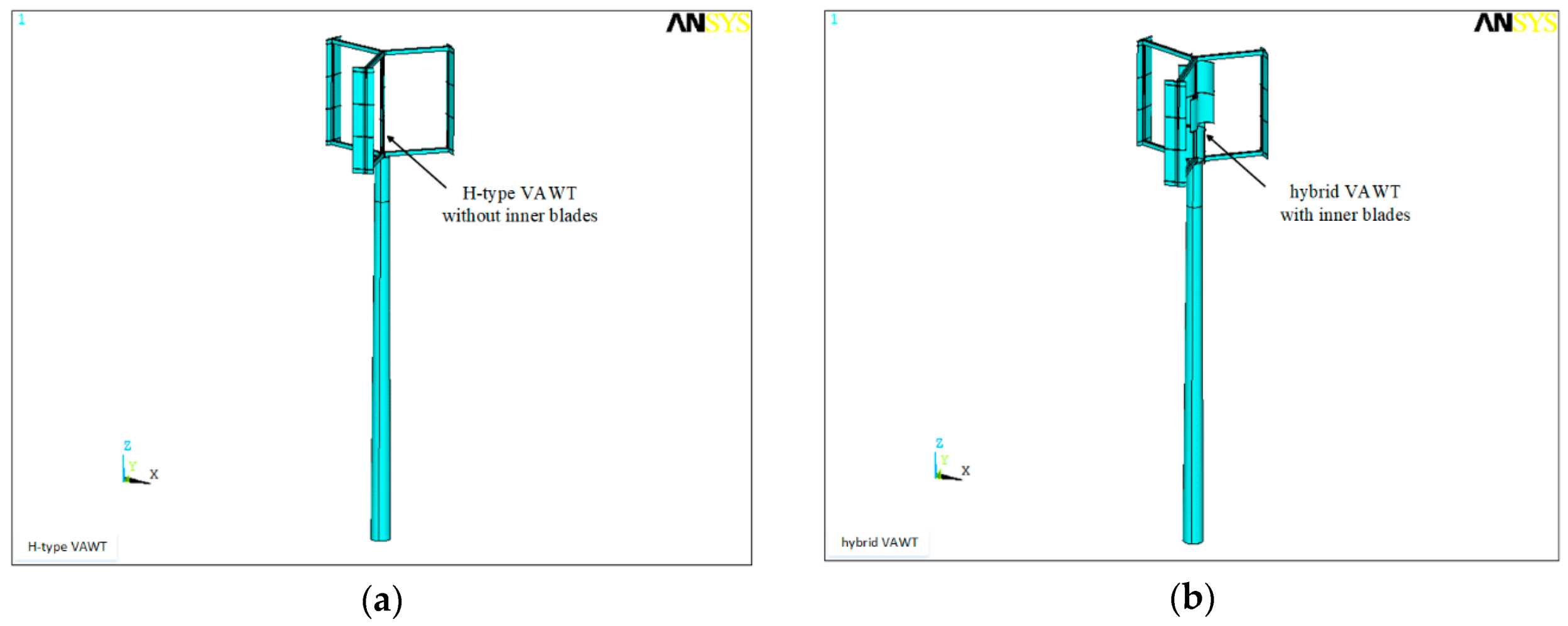
Consider the two VAWTs that have three blades, whose mill diameter is 1.4 m, height is 1 m, and mill weight is 80 kg; the mast height and weight of the turbines are 4 m and 83.6 kg, respectively. The cross-section of the mast is a circle, the diameter of the mast is 0.2 m, and the wall thickness of the mast is 5 mm. The rated power generated by the two VAWTs is 300 W, the rated normal operational wind speed is 10 m/s, and the survival wind speed is 50 m/s. Shapes of the H-type and hybrid VAWTs are shown in Figure 1a,b, respectively.
Most parts of the two VAWTs are similar to each other, which include turbine blades, a turbine shaft, a generator, and the support mast. The main difference between the H-type and hybrid VAWTs is that there are inner blades installed on the shaft of the hybrid VAWT, which can provide a better self-starting capability of the VAWT [7]; the H-type VAWT has no inner blades. Figure 2 shows details of this difference.
3. Free Vibration Analysis of the Two VAWTs
3.1. SDOF Model
Consider an undamped continuous VAWT system that includes a cantilevered mast with the mass per unit length , where is the spatial coordinate, the height , and a turbine with the concentrated mass at its top. Due to the inner blades in the hybrid VAWT, the mass of the hybrid VAWT is larger than that of the H-type VAWT. In this work, the inner blades are assumed to be made of aluminum alloy; the mass of the inner blades of the hybrid VAWT is 10.5 kg, which is 1.49% of its total mass . Therefore, the mass difference between the H-type and hybrid VAWTs is small. The H-type and hybrid VAWTs can be simplified as a cantilever beam with a concentrated mass at its top, as shown in Figure 3.
The taper mast mass can be expressed as where is the mass per unit length of the mast at the bottom, and is the slope coefficient that is given by , where and are radii of bottom and top cross-sections of the mast, respectively. The governing equation of the continuous VAWT system is
where and are Young’s modulus and the area moment of inertia of a cross-section of the mast, respectively, and is the transverse displacement of the system at the position x at time t. Assume that the cross-section of the mast is annular with a uniform thickness . Consider , which is small compared with the diameter of the cross-section of the mast; the area moment of inertia of the cross-section of the mast is
where . Boundary conditions of the system are
where a prime denotes partial differentiation with respect to . By assuming that is a product of a generalized coordinate of a SDOF model of the continuous VAWT system and a shape function :
the assumed modes method [33] is used to derive the free vibration equation of the SDOF model of the continuous system. Substituting Equation (4) into Equation (1) yields
Multiplying Equation (5) by and integrating the resulting equation over yield
Integrating the integral in the first term in Equation (6) by parts and using the first three equations in Equation (3) yield
Substituting Equation (7) into Equation (6) yields
Based on the fourth equation in Equation (3), one has
The free vibration equation of the SDOF model is
where
is the equivalent mass of the SDOF model of the continuous VAWT system, and
is the equivalent stiffness of the SDOF model. In order to select an accurate shape function , one assumes that the shape function is in direct proportion to the static deflection of a uniform cantilevered mast with the same length and any flexible rigidity , subjected to a unit lateral concentrated force at its top: [34]. Hence, one assumes that
where is the maximum displacement of the uniform mast , which yields
If one considers the mast tapering from the 200 mm diameter at the bottom to the 150 mm diameter at the top, the slope coefficient is and the equivalent mass of the mast can be calculated from Equation (11):
Substituting Equations (2) and (14) into Equation (12) yields
The natural frequency of the SDOF model of the continuous VAWT system is given by
3.2. MDOF Model
As shown in Figure 4a,b, the H-type and hybrid VAWTs mainly include three blades, support spokes, the turbine shaft, the generator, and bearings [35] that are small and not shown there. Blades are made of carbon fiber material or aluminum alloy, depending on their required strength and cost. The blades connect to the turbine shaft with several support spokes and bearings. The blades, support spokes, and the turbine shaft are rotating parts of either VAWT. The generator includes a rotor that is a rotating part of either VAWT and a stator that is a non-rotating part, and the mast is a non-rotating part of either VAWT. The rotating and non-rotating parts of either VAWT are connected by bearings.
The turbines are complex mechanical systems that need to be modeled to study their effects on the VAWTs. Use of a simplified MDOF turbine model with a few DOFs can be adequate to describe their low vibration modes. Due to low rotation speeds of the two VAWTs, rotational effects of their rotating parts are not considered in this work; rotational effects can be considered for high rotation speeds [36].
Table 1 summarizes mass and stiffness contributions of each part in the turbines to the simplified MDOF turbine model in vibration analysis. The mass of the upper support spokes and half of the mass of all the blades and the turbine shaft, which are denoted by , are gathered at the top node 1 in Figure 4c. Similarly, the mass of the lower support spokes and half of the mass of all the blades and the turbine shaft, which is denoted by , is gathered at node 2 in Figure 4c. The mass of the generator denoted by is assigned to node 3 in Figure 4c. The stiffness of the turbines comes from the bending stiffness of the turbine shaft; the bending stiffness of beam 1 is that of the turbine shaft between nodes 1 and 2, and the bending stiffness of beam 2 is that of the turbine shaft between nodes 2 and 3. Mass and stiffness values of the simplified MDOF turbine model are listed in Table 1. As indicated earlier, the mass difference between the H-type and hybrid VAWTs is 10.5 kg, which is small, but there is much stiffness difference between the two VAWTs. The MDOF model of the VAWTs is shown in Figure 5. Based on the above discussions, the continuous VAWT system that consists of the taper mast and turbine can be discretized into a number of elements, which can be seen as short beams [28]. There are ten nodes in the MDOF model for the two VAWTs in this study: seven elements for the mast and two elements for the turbines, as shown in Figure 5.
Masses of the two VAWTs are distributed throughout their heights, but are modeled to be concentrated at their ten nodes. The turbines have been modeled by their simplified model shown in Figure 5. There are two DOFs at each node, i.e., the lateral displacement and rotation angle . Stiffness matrices of the VAWTs can be established by applying unit displacements and rotations to their DOFs. For convenience, a simpler model that has only three nodes is shown in Figure 6, and the associated stiffness matrix is calculated below.
By applying unit displacements and rotations, force and moment balance equations for all the elements are established:
where are Young’s moduli of all the elements, are area moments of inertia of cross-sections of all the elements, are lengths of all the elements, are displacements of all the nodes, are rotation angles of all the nodes, are internal forces at all the nodes, and are internal moments at all the nodes. Equations (18)–(23) can be written in the matrix form:
where is the force vector, is the moment vector, is the displacement vector, is the rotating angle vector, and four block matrices in the stiffness matrix are given by
For the MDOF model of the two VAWTs with 10 nodes and 20 DOFs, one can use the same method to derive the force-displacement relationship and the stiffness matrix of the MDOF model [28]:
where
in which are Young’s moduli of all the elements, are moments of inertia of all the elements, are length of all the elements, are displacements of all the nodes, are rotating angles of all the nodes, are forces at all the nodes, and are moments at all the nodes.
Based on Ref. [33], undamped free vibration equations of the MDOF can be written as
where m is the mass matrix that is given by
in which are masses of the 10 elements in the MDOF model, is the stiffness matrix whose block matrices are given earlier, and is the displacement vector.
Natural frequencies and mode shapes of the MDOF model of the two VAWTs for different mast heights can be obtained by solving the eigenvalue problem associated with Equation (35). Natural frequencies are obtained from
where is the nth natural frequency.
3.3. BEM
By employing the commercial software ANSYS, the BEM of the two VAWTs is built to analyze their free vibrations. Pipe-16 beam elements are used in the BEM, and there are 20 elements and 21 nodes in the model. Each node has two DOFs, which are the horizontal displacement and rotation angle. The fixed constraint of the BEM is located at the bottom node, which is consistent with the SDOF and MDOF models of a cantilever beam. Hence, the BEM has 42 DOFs.
A beam model of the mast has two types of modeling methods. In the first method, the mass of the mast is not considered in beam elements, but is assigned at nodes of the beam model, as shown in Figure 7a, while in the second method, the mass of the mast is assigned on beam elements, as shown in Figure 7b; the second method is used in this work. To obtain natural frequencies and mode shapes of the two VAWTs, seven methods can be used for modal analysis in ANSYS: Block Lanczos, Subspace, Power dynamics, Reduced, Unsymmetric, Damped, and Quick response damped. The method of Block Lanczos has fast convergence and is suitable for symmetrical mass and stiffness matrices of large structures, which is adopted in this work. The results are shown in Section 5.3.1.
3.4. SEM
In order to compare with the BEM, SEMs of the two VAWTs are built. The element type of the SEMs is solid-45 in ANSYS. The SEMs of the two VAWTs are built with two steps. The first step is to build 3D geometric models of the two VAWTs. The second step is to mesh the geometric models with the solid-45 element type. A 3D geometric model consists of the mast, blades, support spokes, and the shaft. The mast is a tapered cylindrical tube. The shape of the blades is defined by the airfoil NACA0015 cross-section. The blades are supported by two straight spokes, which are connected to the central shaft. The shaft combines the mast and blades to become a whole VAWT 3D geometric model. The generator is modeled as a mass point located at the joint of the mast and shaft. After the 3D geometric model is built, the second step is taken by meshing the 3D geometric models into the SEMs.
For the H-type VAWT, there are 131,546 nodes and 112,000 elements in its SEM. For the hybrid VAWT, there are 145,154 nodes and 118,615 elements in its SEM. Differences between the two SEMs for the H-type and hybrid VAWTs are at their inner blades. The hybrid VAWT model has inner blades and has 13,608 more nodes and 6165 more elements than the H-type VAWT model. Two types of materials, i.e., aluminum alloy and steel, are used in the SEMs to model different parts of the two VAWTs. For the blades and support spokes in the two VAWTs, aluminum alloy is used because it has a light density and high strength. Hence, it is suitable to make blades since blades should be light and easily rotated by wind. The density of this material is and its Young’s modulus is . Steel is used for the mast and shaft in the two VAWTs because it has a very high strength, which can endure bending moments produced by wind loads. The density of steel is and its Young’s modulus is . For the SEMs of the two VAWTs, a fixed constraint is applied at the bottom of the mast, which can simulate connections of the VAWTs with the ground. The method of Block Lanczos is adopted to obtain natural frequencies and mode shapes of the two VAWTs with modal analysis in ANSYS. The results are shown in Section 5.4.1.
4. Forced Vibration Analysis of the Two VAWTs
4.1. Harmonic Response Analysis
Based on the BEM of the H-type and hybrid VAWTs, their harmonic response analysis can be analyzed by ANSYS. Harmonic response analysis is to apply a series of sinusoidal excitations with different frequencies to a linear system and analyze its steady-state responses under sinusoidal excitations without considering transient responses when the excitations are initially added to the system. Amplitude- and phase-frequency characteristics of the two VAWTs at different nodes can be obtained from their harmonic response analysis based on their BEM, as shown in Section 5.3.2.
4.2. Forced Vibration Analysis
Based on the BEM and SEMs of the H-type and hybrid VAWTs, their forced transient responses can be obtained from ANSYS. Forced transient responses of the two VAWTs consist of two parts. One part is transient responses, which decay as time increases, and the other part is steady-state responses. Forced transient response analysis is called transient dynamic analysis in ANSYS. Three methods can be used for transient dynamic analysis: full method, reduced method, and modal superposition method. Use of complete system matrices to calculate transient response is called the full method, which is used here. This method has no matrix reduction and is the most powerful of the three methods, allowing various nonlinear characteristics to be accounted for. Forces applied to the BEM and SEMs of the two VAWTs are aerodynamic loads obtained from CFD simulation in Section 4.3. To obtain forced transient responses of the two VAWTs, the time-varying aerodynamics loads from CFD simulation are applied to the BEM and SEMs. By choosing the Newmark algorithm in ANSYS and setting structural damping factors α = 0.001 and β = 0.0005, displacement responses of the two VAWTs are obtained.
4.3. Time-Varying Aerodynamic Loads on the Two VAWTs
Time-varying aerodynamic loads on the H-type and hybrid VAWTs are calculated from high-fidelity unsteady Reynolds averaged Navier-Stokes (URANS) CFD simulation [7], which calculates aerodynamic loads on the two VAWTs. Aerodynamic loading is important to the performance of the VAWTs. The URANS model is simulated using the ANSYS® Fluent® 15.0 high-performance computing software. For pressure-velocity coupling, the semi-implicit method for pressure-linked equations (SIMPLE) algorithm with a second-order upwind spatial discretization scheme is utilized to solve the URANS equations. A second-order implicit transient formulation is selected to ensure the accuracy of time integration. The inlet turbulence viscosity ratio is set to 10 to give a reasonable estimation of the free stream turbulence. Additionally, for each inner iteration, the residual convergence criterion is fixed at for better converged results. The Reynolds number based on the diameter of the two VAWTs is approximately . The numerical setup is summarized in Table 2 and more details can be found in Ref. [7]. In the simulation, the angular velocity of the two VAWTs is set to 16.625 rad/s when the wind speed is 5 m/s at the steady operational status and the corresponding TSR is 2.3. Time histories of aerodynamic loads on three outer blades (i.e., blades 1, 2, and 3) of the two VAWTs and inner blades of the hybrid VAWT are shown in Figure 8. Note that the free stream direction is denoted as the X-direction, and the direction perpendicular to the free stream and within the cross-sectional plane of a turbine is denoted as the Y-direction. The Z-direction is defined from X- and Y-directions by the right-hand rule. The aerodynamic loads at any specific time are calculated via integration of both the pressure and viscous forces over blade surfaces. In Figure 8, blue solid lines, black dashed lines, and red dotted lines represent forces on the three outer blades, green two-dot chain lines represent forces on the three inner blades of the hybrid VAWT, and navy-blue solid lines represent resultant forces on all the blades of the two VAWTs. All these forces periodically vary with time. Instantaneous vorticity fields around the H-type VAWT from CFD simulation are shown in Figure 9a and those around the hybrid VAWT are shown in Figure 9b.
5. Numerical Results and Discussions
5.1. SDOF Results
Mast parameters of the SDOF model of the H-type and hybrid VAWTs are listed in Table 3. For different mast parameters with the mast height varying from 1 to 4 m and the mast diameter varying from 66.7 to 200 mm, natural frequencies of the SDOF model of the H-type and hybrid VAWTs are obtained from Equation (17), as shown in Table 4, where cross-section dimensions, lengths, and densities of each element of the mast of the two VAWTs are specified. The natural frequency decreases with the mast height for both the H-type and hybrid VAWTs.
5.2. MDOF Results
Geometric properties of the MDOF model of the H-type and hybrid VAWTs with different mast heights are listed in Table 5. Table 6 shows the first three natural frequencies of the H-type VAWT with different mast heights. Natural frequencies of the MDOF model of the VAWTs decrease with the mast height. More specifically, the first natural frequency drops from 3.73 to 2.07 Hz, the second natural frequency drops from 399.4 to 50.0 Hz, and the third natural frequency drops from 1004 to 150.5 Hz when the mast height increases from 1 to 4 m. There is 3.67% difference between the first natural frequencies of the SDOF and MDOF models for the 1 m-mast height; the differences are 3.12% for the second natural frequencies and 3.50% for the third natural frequencies. Similar results are obtained for the 2 and 4 m-mast heights.
Table 7 shows the first three natural frequencies of the MDOF model of the hybrid VAWT. Natural frequencies of the MDOF model decrease with the mast height. More specifically, the first natural frequency drops from 3.98 to 2.05 Hz, the second natural frequency drops from 412.4 to 69 Hz, and the third natural frequency drops from 1105 to 166.8 Hz when the mast height increases from 1 to 4 m. There is 3.25% difference between the first natural frequencies of the SDOF and MDOF models for the 1 m-mast height; the differences are 3.53% for the second natural frequencies and 3.02% for the third natural frequencies. Similar results are obtained for the 2 and 4 m-mast heights.
5.3. BEM Results
5.3.1. Free Vibration
According to Section 3.3 above, the BEM has 21 nodes and 42 DOFs for the H-type and hybrid VAWTs; this model has more DOFs than the SDOF and MDOF models, which have one DOF for the SDOF model and ten nodes and 20 DOFs for the MDOF model. With numbers of nodes and DOFs increasing, natural frequencies can be more accurately calculated from the BEM. Table 8 shows comparison between the first three natural frequencies of the MDOF model and BEM of the H-type VAWT with different mast heights. For the 1 m-mast height, there is 3.54% difference between the first natural frequencies of the SDOF and MDOF models; the differences are 3.22% for the second natural frequencies and 0.49% for the third natural frequencies. Similar results are obtained for the 2 and 4 m-mast heights. Figure 10a–c show the first, second, and third mode shapes of the BEM of the 4 m-mast H-type VAWT, respectively.
Table 9 shows comparison between the first three natural frequencies of the MDOF model and BEM of the hybrid VAWT with different mast heights. For the 1 m-mast height, there is 3.16% difference between the first natural frequencies of the SDOF and MDOF; the differences are 0.22% for the second natural frequencies and 1.92% for the third natural frequencies. Similar results are obtained for the 2 and 4 m-mast heights. The first three mode shapes of the hybrid VAWT are similar to those of the H-type VAWT shown in Figure 10.
5.3.2. Forced Vibration Results
Amplitude-frequency responses of the H-type and hybrid VAWTs can be obtained from harmonic response analysis in ANSYS. Figure 11 shows amplitude-frequency responses of the 1 m-mast H-type and hybrid VAWTs in X- and Y-directions. From Figure 11a,b, one can find that the first three resonance frequencies of the H-type VAWT are 3.6, 386.9, and 999.4 Hz, respectively, in both X- and Y-directions. The first three resonance frequencies of the hybrid VAWT in both X- and Y-directions are 3.73, 411.5, and 1084 Hz, respectively. The first resonance frequency of the H-type VAWT is 3.6% lower than that of the hybrid VAWT for the 1 m-mast height, since inner blades of the hybrid VAWT provide more overall stiffness effect than overall mass effect compared with the H-type VAWT. The first resonance frequency is the main one, and one can conclude that for the 1 m-mast height, the hybrid VAWT has better performance than the hybrid VAWT in terms of increasing its resonance frequencies. Since the mast is made of steel and inner blades are made of aluminum alloy, increase in the stiffness and natural frequencies of the hybrid VAWT is limited.
Figure 12 shows amplitude-frequency responses of the 4 m-mast H-type and hybrid VAWTs in X- and Y-directions. From Figure 12a,b, one can find that the first three resonance frequencies of the H-type VAWT are 1.9, 48.9, and 150.4 Hz, respectively, in both X- and Y-directions. The first three resonance frequencies of the hybrid VAWT in both X- and Y-directions are 1.9, 66.6, and 167.3 Hz, respectively. The first resonance frequency of the H-type VAWT is the same as that of the hybrid VAWT, and the second and third resonance frequencies of the H-type VAWT are smaller than those of the hybrid VAWT for the 4 m-mast height.
Figure 13 shows forced transient responses of the 1 m-mast H-type and hybrid VAWTs in X- and Y-directions under aerodynamic loads shown in Figure 9, where Figure 13a,b shows global forced transient responses of the two VAWTs in the X- and Y-directions, and Figure 13c,d shows forced transient responses of the two VAWTs in the X- and Y-directions at the steady state, in which points with the maximum absolute response amplitudes are connected together to better show the steady-state response amplitudes. The maximum steady-state response amplitudes of the two VAWTs are shown in Table 10. As can be seen in Table 10, the maximum steady-state response amplitudes of the H-type and hybrid VAWTs in the X-direction are and , respectively. The maximum steady-state response amplitude of the hybrid VAWT is 26.9% smaller than that of the H-type VAWT in the X-direction. The maximum steady-state response amplitudes of the H-type and hybrid VAWTs in the Y-direction are and , respectively. The maximum steady-state response amplitude of the hybrid VAWT is 22.6% smaller than that of the H-type VAWT in the Y-direction. Steady-state response amplitudes of the H-type and hybrid VAWTs in the X-direction are 11.1% and 14.9% smaller than those in the Y-direction, respectively.
Figure 14 shows forced transient responses of the 4 m-mast H-type and hybrid VAWTs in X- and Y-directions, where Figure 14a,b shows global forced transient responses of the two VAWTs in the X- and Y-directions, and Figure 14c,d shows forced transient responses of the two VAWTs in the X- and Y-directions at the steady state, in which points with the maximum absolute response amplitudes are connected together to better show the maximum steady-state response amplitudes. The maximum steady-state response amplitudes of the two VAWTs are shown in Table 11. As can be seen in Table 11, the maximum steady-state response amplitudes of the H-type and hybrid VAWTs in the X-direction are and , respectively. The maximum steady-state response amplitude of the hybrid VAWT in the X-direction is 24.6% larger than that of the H-type VAWT in the X-direction. The maximum steady-state response amplitudes of the H-type and hybrid VAWTs in the Y-direction are and , respectively. The maximum steady-state response amplitude of the hybrid VAWT is 31.6% larger than that of the H-type VAWT in the Y-direction. Steady-state response amplitudes of the H-type and hybrid VAWTs in the X-direction are 5.76% and 11.8% smaller than those in the Y-direction, respectively.
5.4. SEM Results
5.4.1. Free Vibration Results
SEM models of the 1 m-mast H-type and hybrid VAWTs are built to simulate the two VAWTs. The first three natural frequencies of the two VAWTs from their SEMs that correspond to their X-Y planar motions are shown in Table 12 and they are compared with the first three natural frequencies of the two VAWTs from their BEM there. The first three natural frequencies of the H-type VAWT from its SEM that correspond to its X-Y planar motion are 3.65, 402.5, and 1032 Hz, respectively, and those of the hybrid VAWT are 3.79, 429.2, and 1121 Hz, respectively. Since the first natural frequency of the H-type VAWT is lower than that of the H-type VAWT, the hybrid VAWT has better performance than the H-type VAWT. Differences between the first three natural frequencies of the H-type VAWT from its BEM and SEM are 1.39, 4.03, and 3.26%, respectively. Differences between the first three natural frequencies of the hybrid VAWT from its BEM and SEM are 1.61, 4.30, and 3.41%, respectively.
SEMs of the 4 m-mast H-type and hybrid VAWTs are also built to simulate the two VAWTs. The first three natural frequencies of the two 4 m-mast VAWTs from their SEMs that correspond to their X-Y planar motions are shown in Table 13 and compared with the first three natural frequencies of the two VAWTs from their BEM there. The first three natural frequencies of the H-type VAWT from their SEMs that correspond to their X-Y planar motions are 1.92, 50.2, and 154.1 Hz, respectively, and those of the hybrid VAWT are 1.90, 66.9, and 170.4 Hz, respectively. The first three mode shapes of the H-type and hybrid VAWTs that correspond to their X-Y planar motions are shown in Figure 15 and Figure 16, respectively. They are in agreement with the first three mode shapes of the H-type VAWT from its BEM in Figure 10b–d.
5.4.2. Forced vibration results
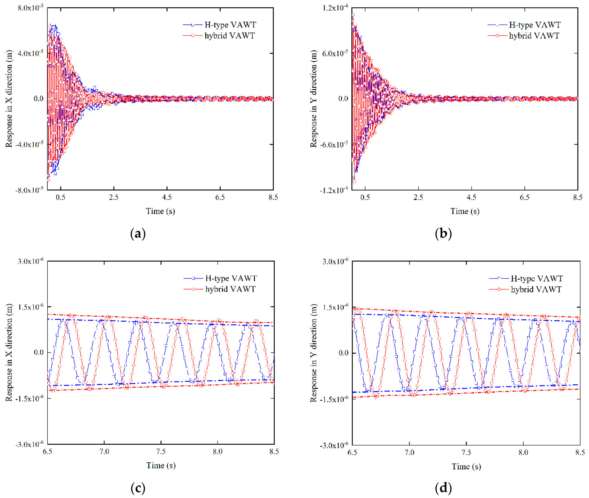
Figure 17 shows forced transient responses of the 1 m-mast H-type and hybrid VAWTs in X- and Y-directions, where Figure 17a,b shows global forced transient responses of the two VAWTs in the X- and Y-directions, and Figure 17c,d shows forced transient responses of the two VAWTs in the X- and Y-directions at the steady state, in which points with the maximum absolute response amplitudes are connected together to better show the steady-state response amplitudes. The maximum steady-state response amplitudes of the two VAWTs are shown in Table 14. As can be seen in Table 14, the maximum steady-state response amplitudes of the H-type and hybrid VAWTs in the X-direction are and , respectively. The maximum steady-state response amplitude of the hybrid VAWT is 23.8% smaller than that of the H-type VAWT in the X-direction. The maximum steady-state response amplitudes of the H-type and hybrid VAWTs in the Y-direction are and , respectively. The maximum steady-state response amplitude of the hybrid VAWT is 20.5% smaller than that of the H-type VAWT in the Y-direction. Steady-state response amplitudes of the H-type and hybrid VAWTs in the X-direction are 17.4% and 20.1% smaller than those in the Y-direction, respectively.
Figure 18 shows forced transient responses of the 4 m-mast H-type and hybrid VAWTs in X- and Y-directions, where Figure 17a,b shows global forced transient responses of the two VAWTs in the X- and Y-directions, and Figure 18c,d shows forced transient responses of the two VAWTs in the X- and Y-directions at the steady state, where points with the maximum absolute response amplitudes are connected together to better show the steady-state response amplitudes. The maximum steady-state response amplitudes of the two VAWTs are shown in Table 15. As can be seen in Table 15, the maximum steady-state response amplitudes of the H-type and hybrid VAWTs in the X-direction are and , respectively. The maximum steady-state response amplitude of the hybrid VAWT is 22.8% larger than that of the H-type VAWT in the X-direction. The maximum steady-state response amplitudes of the H-type VAWT and hybrid VAWT in the Y-direction are and , respectively. The maximum steady-state response amplitude of the hybrid VAWT is 24.3% larger than that of the H-type VAWT in the Y-direction. Steady-state response amplitudes of the H-type and hybrid VAWTs in the X-direction are 13.8% and 15.3% smaller than those in the Y-direction, respectively.
5.5. Aerodynamic Excitation Frequency Analysis
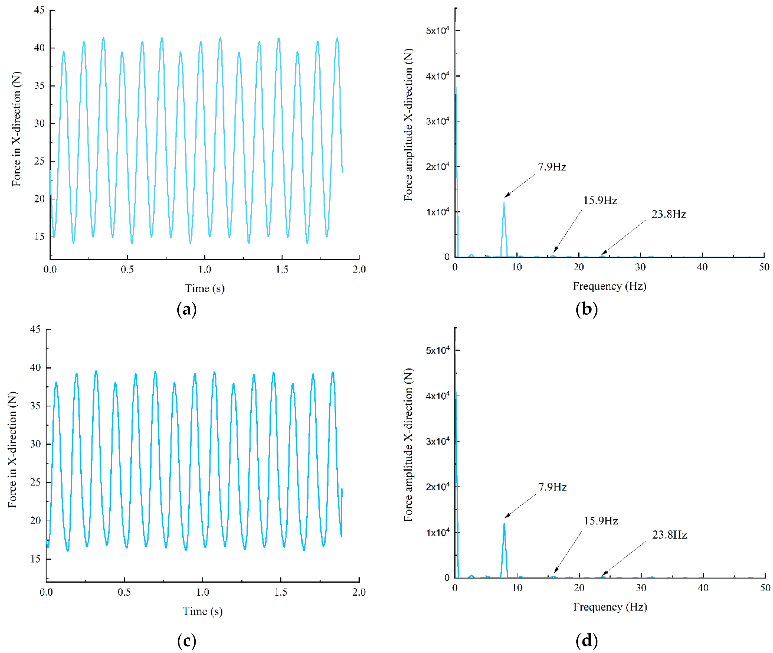
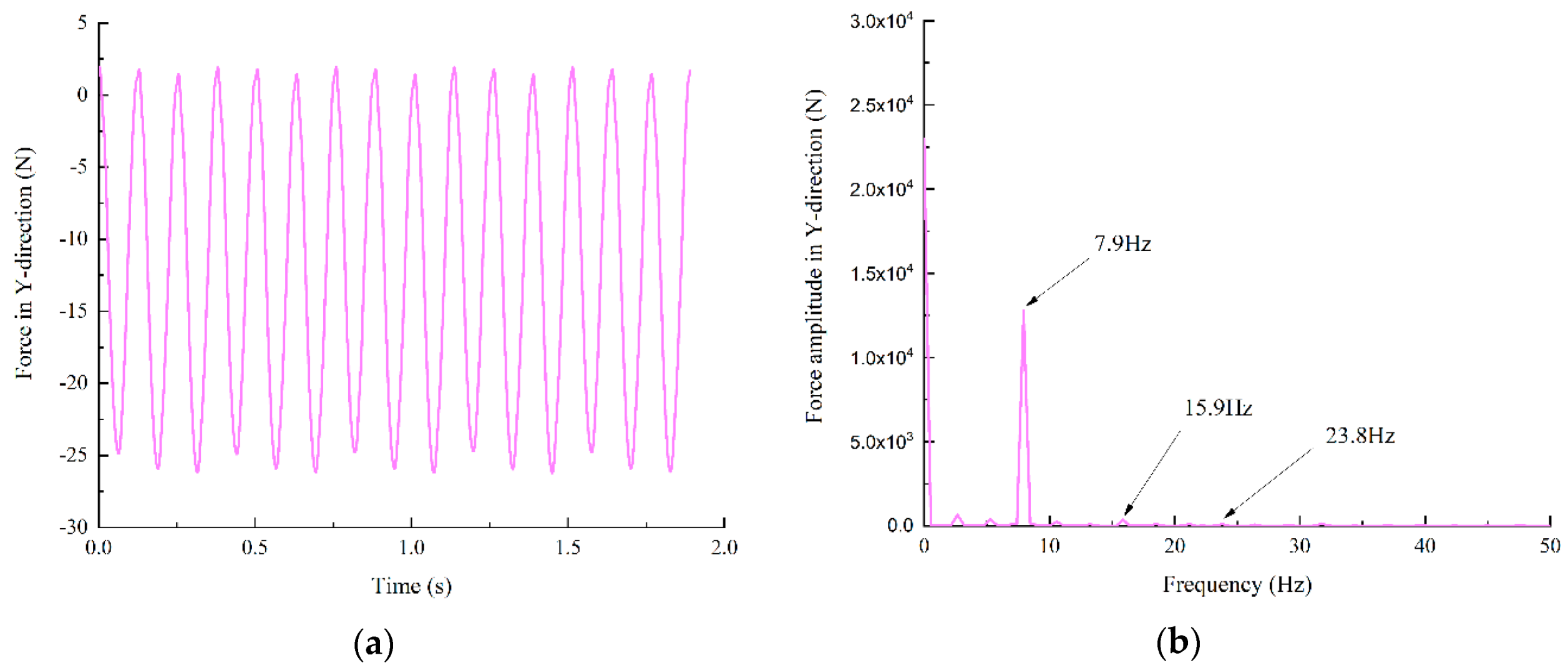
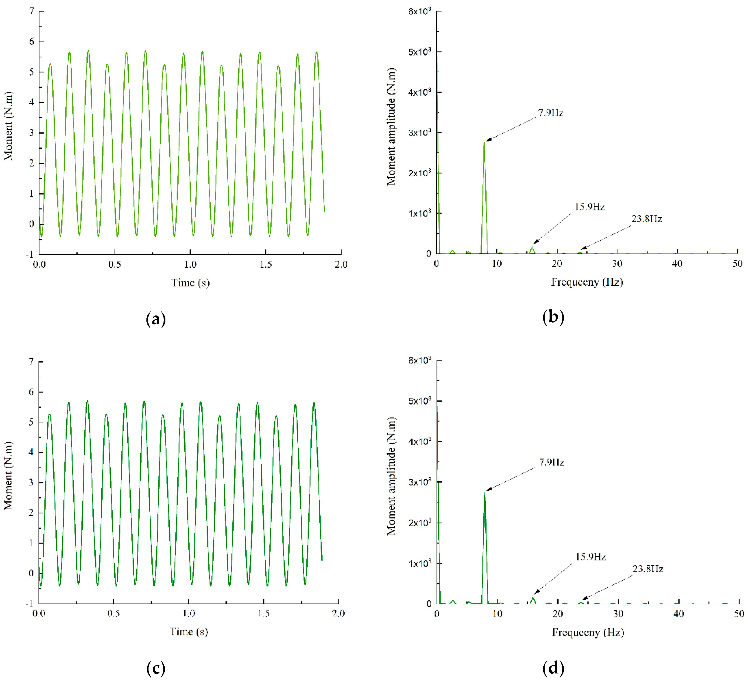
Since aerodynamic loading on the two VAWTs is a periodic excitation, resonance can occur when an excitation frequency is close to some natural frequencies of the two VAWTs. Therefore, excitation frequencies of the aerodynamic loading are determined in this section. Resultant aerodynamic loads acting on all blades of the H-type and hybrid VAWTs in the X-direction and their dominant excitation frequencies are shown in Figure 19, where the fast Fourier transform (FFT) is taken over the aerodynamic loads to find the dominant excitation frequencies. Based on the FFT analysis, dominant excitation frequencies of the resultant aerodynamic loads are 7.9 Hz, 15.9 Hz, and 23.8 Hz. Note that the higher frequencies are about twice or three times of the fundamental frequency, which confirms that the resultant aerodynamic loads have good periodicity. To ensure that aerodynamic excitation does not cause resonance, natural frequencies of the VAWTs should not be close to these excitation frequencies in their structural design. Similarly, resultant aerodynamic loads acting on all blades of the H-type and hybrid VAWTs in the Y-direction and their dominant excitation frequencies are shown in Figure 20, which also confirms that they have good periodicity. Dominant excitation frequencies of the resultant aerodynamic loads on all blades in the Y-direction are the same as those in the X-direction. Note that aerodynamic loads in X- and Y-directions are applied on turbine shafts of the two VAWTs by all their blades. Moments produced by aerodynamic loads in X- and Y-directions along the Z-direction on the two VAWTs are shown in Figure 21. As expected, the aerodynamic moments along the Z-direction have the same dominant excitation frequencies as those of the aerodynamic loads in X- and Y-directions and are hence periodic.
5.6. Power Efficiency Analysis
According to Ref. [12], the power efficiency or coefficient of the two VAWTs is defined as
where is the power output of the VAWTs, and is the power available in incoming wind flow. They are defined as
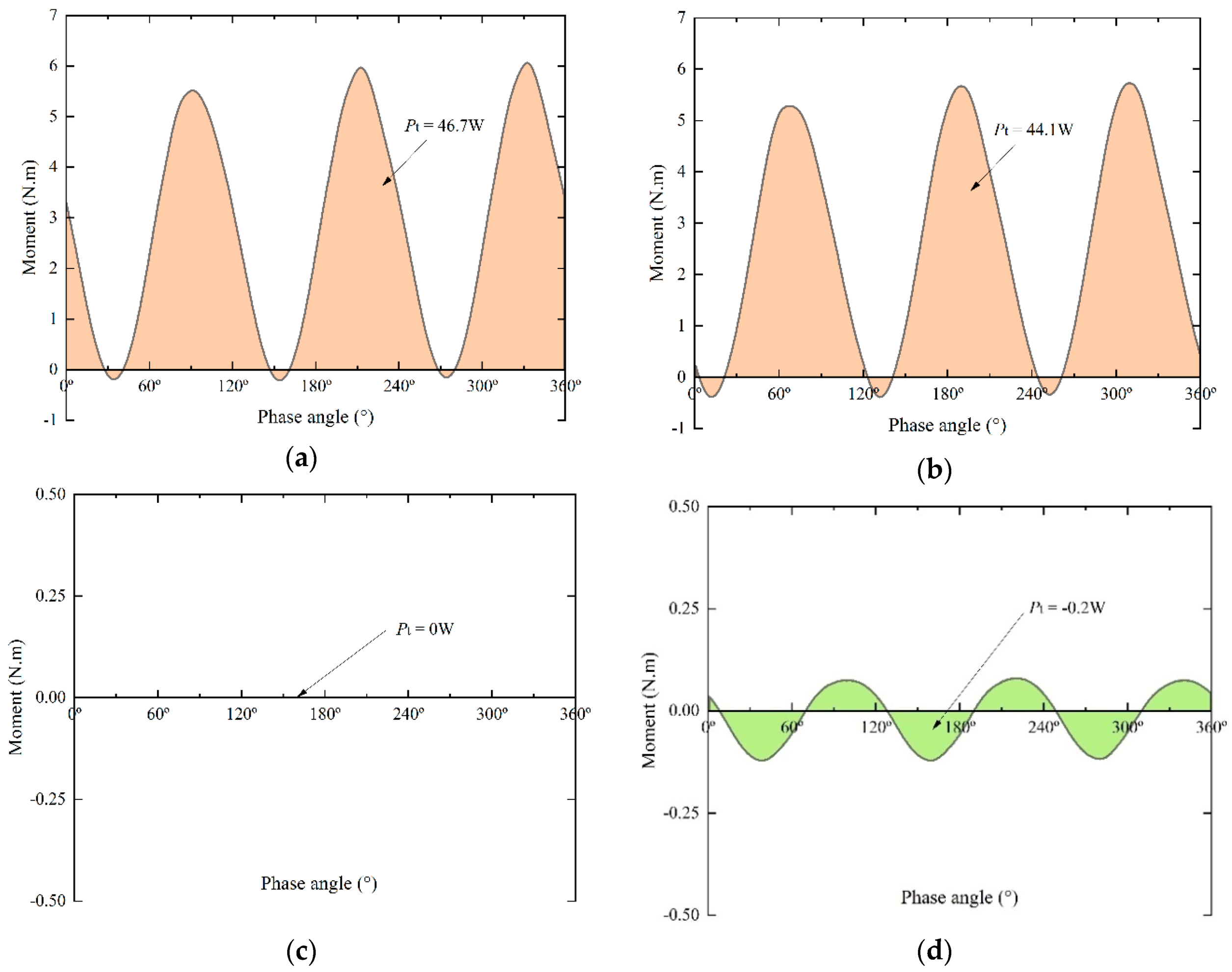
where is the angular velocity of the VAWTs, is the time-dependent moment from all blades of the VAWTs, is their rotation period, is the number of periods, is the stream density, is the free stream velocity, is the radius of the VAWTs, and is the height of their blades. In this work, , , , , , and the TSR is 2.3; hence, , and for the H-type VAWT and for the hybrid VAWT. According to CFD simulation, the power coefficient of the H-type VAWT is and that of the hybrid VAWT is . The power efficiency of the H-type VAWT is 2.6% higher than that of the hybrid VAWT.
Figure 22 shows aerodynamic moments as a function of the phase angle that varies from 0 to 360° and corresponding output powers of the H-type and hybrid VAWTs. It is seen from Figure 22 that a total of 43.9 W is generated by the hybrid VAWT, where 44.1 W is generated by its outer blades and −0.2 W by its inner blades. The outer blades play a dominant role in the power generation process of the hybrid VAWT. While the effect of the inner blades on its power generation is minimal, they can significantly enhance its self-starting capability [7].
6. Conclusions
This work studies free and forced vibrations of the H-type and hybrid VAWTs. Based on the above analysis results, some conclusions can be obtained as follows:
- (1)
- Differences between natural frequencies of the SDOF model of the H-type and hybrid VAWTs and the first natural frequencies of their MDOF model range from 3.12% to 3.67% and from 3.02% to 3.53%, respectively, when the mast height varies from 1 to 4 m, which means that the SDOF model is a useful model to analyze the first natural frequencies of the two VAWTs.
- (2)
- Differences between the first three natural frequencies of the MDOF model of the H-type and hybrid VAWTs and those of their BEM range from 0.13% to 3.54% and from 0.12% to 3.92%, respectively, when the mast height varies from 1 to 4 m, which means that the MDOF model is a useful and reasonably simplified model to analyze free vibrations of the two VAWTs.
- (3)
- Differences between the first three natural frequencies of the BEM of the H-type and hybrid VAWTs and corresponding natural frequencies of their SEMs range from 1.39% to 4.03% and from 1.61% to 4.30%, respectively, when the mast height varies from 1 and 4 m, which means that the BEM is a useful and reasonably simplified model to analyze free vibrations of the two VAWTs.
- (4)
- Based on their SEMs, for the 1 m-mast height, the first natural frequency of the H-type VAWT is 3.69% smaller than that of the hybrid VAWT. For the 4m-mast height, the first natural frequency of the H-type VAWT is 1.05% larger than that of the hybrid VAWT. For the 1 m-mast height, steady-state forced response amplitudes of the H-type VAWT are 23.8% and 20.5% larger than those of the hybrid VAWT in X- and Y-directions, respectively. For the 4 m-mast height, steady-state forced response amplitudes of the H-type VAWT are 22.8% and 24.3% smaller than those of the hybrid VAWT in X- and Y-directions, respectively. For the 1 m-mast H-type and hybrid VAWTs, the maximum steady-state response amplitudes in the X-direction are 17.4% and 20.1% smaller than those the Y-direction, respectively. For the 4m-mast H-type and hybrid VAWTs, the maximum steady-state response amplitudes in the X-direction are 13.8% and 15.3% smaller than those in the Y-direction, respectively.
- (5)
- Aerodynamic forces and moments on blades of the two VAWTs are periodic. Outer blades of the hybrid VAWT play a dominant role in its power generation process. While inner blades of the hybrid VAWT have a minimal effect on its power generation, they can significantly enhance its self-starting capability.
Author Contributions
Conceptualization, W.Z. and M.Y.; methodology, W.Z. and X.Z.; software, M.T.; validation, X.Z. and K.L.; formal analysis, X.Z.; investigation, M.T.; resources, G.L.; data curation, K.L. and G.L.; writing—original draft preparation, M.T.; writing—review and editing, W.Z. and M.Y.; visualization, K.L.; supervision, W.Z.; project administration, W.Z.; and funding acquisition, W.Z. and M.Y. All authors have read and agreed to the published version of the manuscript.
Funding
This research was funded by the Maryland Offshore Wind Energy Research Challenge Grant from the Maryland Higher Education Commission through grant number MOWER 14-03 and Maryland Innovation Initiative Grants from the Maryland Technology Development Corporation.
Acknowledgments
The authors would like to acknowledge the Maryland Higher Education Commission and Maryland Technology Development Corporation for their financial support. They would like to thank the anonymous reviewers for their comments.
Conflicts of Interest
The authors declare no conflict of interest.
References
- American Wind Energy Association (AWEA). Wind Powers America Annual Report; American Wind Energy Association (AWEA): Washington, DC, USA, 2019.
- Wilburn, D.R. Wind Energy in the United States and Materials Required for the Land-Based Wind Turbine Industry from 2010 through 2030; US Department of the Interior: US Geological Survey: Washington, DC, USA, 2011.
- Bianchini, A.; Balduzzi, F.; Di Rosa, D.; Ferrara, G. On the use of Gurney Flaps for the aerodynamic performance augmentation of Darrieus wind turbines. Energy Convers. Manag. 2019, 184, 402–415. [Google Scholar]
- Han, H.; Liu, L.; Cao, D. Dynamic modeling for rotating composite Timoshenko beam and analysis on its bending-torsion coupled vibration. Appl. Math. Modell. 2020, 78, 773–791. [Google Scholar]
- Castelli, M.R.; Giulia, S.; Ernesto, B. Numerical analysis of the influence of airfoil asymmetry on VAWT performance. World Acad. Sci. Eng. Technol. 2012, 61, 312–321. [Google Scholar]
- Bianchini, A.; Balduzzi, F.; Ferrara, G.; Ferrari, L. Virtual incidence effect on rotating airfoils in Darrieus wind turbines. Energy Convers. Manag. 2016, 111, 329–338. [Google Scholar]
- Liu, K.; Yu, M.; Zhu, W. Enhancing wind energy harvesting performance of vertical axis wind turbines with a new hybrid design: A fluid-Structure interaction study. Renew. Energy 2019, 140, 912–927. [Google Scholar]
- Zanforlin, S.; Nishino, T. Fluid dynamic mechanisms of enhanced power generation by closely spaced vertical axis wind turbines. Renew. Energy 2016, 99, 1213–1226. [Google Scholar]
- Abdalrahman, G.; Melek, W.; Lien, F.-S. Pitch angle control for a small-scale Darrieus vertical axis wind turbine with straight blades (H-Type VAWT). Renew. Energy 2017, 114, 1353–1362. [Google Scholar]
- Chen, W.-H.; Chen, C.-Y.; Huang, C.-Y.; Hwang, C.-J. Power output analysis and optimization of two straight-bladed vertical-axis wind turbines. Appl. Energy 2017, 185, 223–232. [Google Scholar]
- Joo, S.; Choi, H.; Lee, J. Aerodynamic characteristics of two-bladed H-Darrieus at various solidities and rotating speeds. Energy 2015, 90, 439–451. [Google Scholar]
- Bhargav, M.; Kishore, V.R.; Laxman, V. Influence of fluctuating wind conditions on vertical axis wind turbine using a three dimensional CFD model. J. Wind Eng. Ind. Aerodyn. 2016, 158, 98–108. [Google Scholar]
- Dessoky, A.; Lutz, T.; Bangga, G.; Krämer, E. Computational studies on Darrieus VAWT noise mechanisms employing a high order DDES model. Renew. Energy 2019, 143, 404–425. [Google Scholar] [CrossRef]
- Lositaño, I.C.M.; Danao, L.A.M. Steady wind performance of a 5 kW three-Bladed H-Rotor Darrieus Vertical Axis Wind Turbine (VAWT) with cambered tubercle leading edge (TLE) blades. Energy 2019, 175, 278–291. [Google Scholar] [CrossRef]
- Molina, A.C.; De Troyer, T.; Massai, T.; Vergaerde, A.; Runacres, M.C.; Bartoli, G. Effect of turbulence on the performance of VAWTs: An experimental study in two different wind tunnels. J. Wind Eng. Ind. Aerodyn. 2019, 193, 103969. [Google Scholar] [CrossRef]
- Vergaerde, A.; De Troyer, T.; Molina, A.C.; Standaert, L.; Runacres, M. Design, manufacturing and validation of a vertical-axis wind turbine setup for wind tunnel tests. J. Wind Eng. Ind. Aerodyn. 2019, 193, 103949. [Google Scholar] [CrossRef]
- Peng, H.; Lam, H.; Liu, H. Power performance assessment of H-Rotor vertical axis wind turbines with different aspect ratios in turbulent flows via experiments. Energy 2019, 173, 121–132. [Google Scholar] [CrossRef]
- Benner, B.M.; Carlson, D.W.; Seyed-Aghazadeh, B.; Modarres-Sadeghi, Y. Vortex-Induced Vibration of symmetric airfoils used in Vertical-Axis Wind Turbines. J. Fluids Struct. 2019, 91, 102577. [Google Scholar] [CrossRef]
- Buchner, A.; Lohry, M.W.; Martinelli, L.; Soria, J.; Smits, A.J. Dynamic stall in vertical axis wind turbines: Comparing experiments and computations. J. Wind Eng. Ind. Aerodyn. 2015, 146, 163–171. [Google Scholar] [CrossRef]
- Guo, Y.; Li, X.; Sun, L.; Gao, Y.; Gao, Z.; Chen, L. Aerodynamic analysis of a step adjustment method for blade pitch of a VAWT. J. Wind Eng. Ind. Aerodyn. 2019, 188, 90–101. [Google Scholar] [CrossRef]
- Chen, C.-C.; Kuo, C.-H. Effects of pitch angle and blade camber on flow characteristics and performance of small-size Darrieus VAWT. J. Vis. 2013, 16, 65–74. [Google Scholar] [CrossRef]
- Sengupta, A.; Biswas, A.; Gupta, R. Comparison of low wind speed aerodynamics of unsymmetrical blade H-Darrieus rotors-blade camber and curvature signatures for performance improvement. Renew. Energy 2019, 139, 1412–1427. [Google Scholar] [CrossRef]
- Yao, Y.; Tang, Z.; Wang, X. Design based on a parametric analysis of a drag driven VAWT with a tower cowling. J. Wind Eng. Ind. Aerodyn. 2013, 116, 32–39. [Google Scholar] [CrossRef]
- Maeda, T.; Kamada, Y.; Shimizu, K.; Ogasawara, T.; Nakai, A.; Kasuya, T. Effect of rotor aspect ratio and solidity on a straight-Bladed vertical axis wind turbine in three-dimensional analysis by the panel method. Energy 2017, 121, 1–9. [Google Scholar]
- Huang, D.; Zhou, S.; Han, Q.; Litak, G. Response analysis of the nonlinear vibration energy harvester with an uncertain parameter. Proc. Inst. Mech. Eng. Part K J. Multi-Body Dyn. 2020, 234, 393–407. [Google Scholar] [CrossRef]
- Han, H.; Cao, D.; Liu, L. A new approach for steady-State dynamic response of axially functionally graded and non-uniformed beams. Compos. Struct. 2019, 226, 111270. [Google Scholar] [CrossRef]
- Huan, R.; Pu, D.; Wang, X.; Wei, X. Effects of phase delay on synchronization in a nonlinear micromechanical oscillator. Appl. Phys. Lett. 2019, 114, 233501. [Google Scholar] [CrossRef]
- Verkinderen, E.; Imam, B. A simplified dynamic model for mast design of H-Darrieus vertical axis wind turbines (VAWTs). Eng. Struct. 2015, 100, 564–576. [Google Scholar] [CrossRef]
- Wang, Y.; Lu, W.; Dai, K.; Yuan, M.; Chen, S.-E. Dynamic study of a rooftop vertical axis wind turbine tower based on an automated vibration data processing algorithm. Energies 2018, 11, 3135. [Google Scholar] [CrossRef] [Green Version]
- Rahman, M.; Ong, Z.C.; Chong, W.T.; Julai, S.; Khoo, S.Y. Performance enhancement of wind turbine systems with vibration control: A review. Renew. Sustain. Energy Rev. 2015, 51, 43–54. [Google Scholar] [CrossRef]
- Mabrouk, I.B.; El Hami, A.; Walha, L.; Zghal, B.; Haddar, M. Dynamic vibrations in wind energy systems: Application to vertical axis wind turbine. Mech. Syst. Signal Process. 2017, 85, 396–414. [Google Scholar] [CrossRef]
- Yan, Y.; Wiercigroch, M. Dynamics of rotary drilling with non-uniformly distributed blades. Int. J. Mech. Sci. 2019, 160, 270–281. [Google Scholar] [CrossRef]
- Meirovitch, L. Principles and Techniques of Vibrations; Prentice Hall: Upper Saddle River, NJ, USA, 1997; Volume 1. [Google Scholar]
- Chopra, A.K. Dynamics of Structures, Theory and Applications to Earthquake Engineering; Pearson-Prentice Hall: Upper Saddle River, NJ, USA, 2012. [Google Scholar]
- Xie, Z.; Liu, H. Experimental research on the interface lubrication regimes transition of water lubricated bearing. Mech. Syst. Signal Process. 2020, 136, 106522. [Google Scholar] [CrossRef]
- Chen, W.; Rajan, S.; Nelson, H.; Rajan, M. Application of nonlinear programming for balancing rotor systems. Eng. Optim. 1991, 17, 79–90. [Google Scholar] [CrossRef]
Figure 1.
Shapes of the (a) H-type and (b) hybrid VAWTs, where the hybrid VAWT has inner blades and the H-type VAWT does not have them.
Figure 1.
Shapes of the (a) H-type and (b) hybrid VAWTs, where the hybrid VAWT has inner blades and the H-type VAWT does not have them.

Figure 2.
Details of blades of the (a) H-type and (b) hybrid VAWTs.
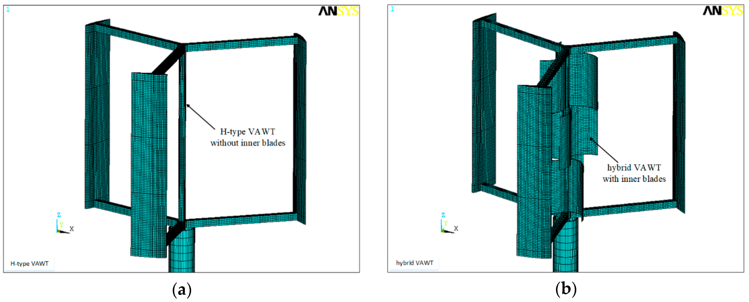
Figure 3.
Continuous VAWT system that is modeled as a cantilever beam with a concentrated mass at its top.
Figure 3.
Continuous VAWT system that is modeled as a cantilever beam with a concentrated mass at its top.
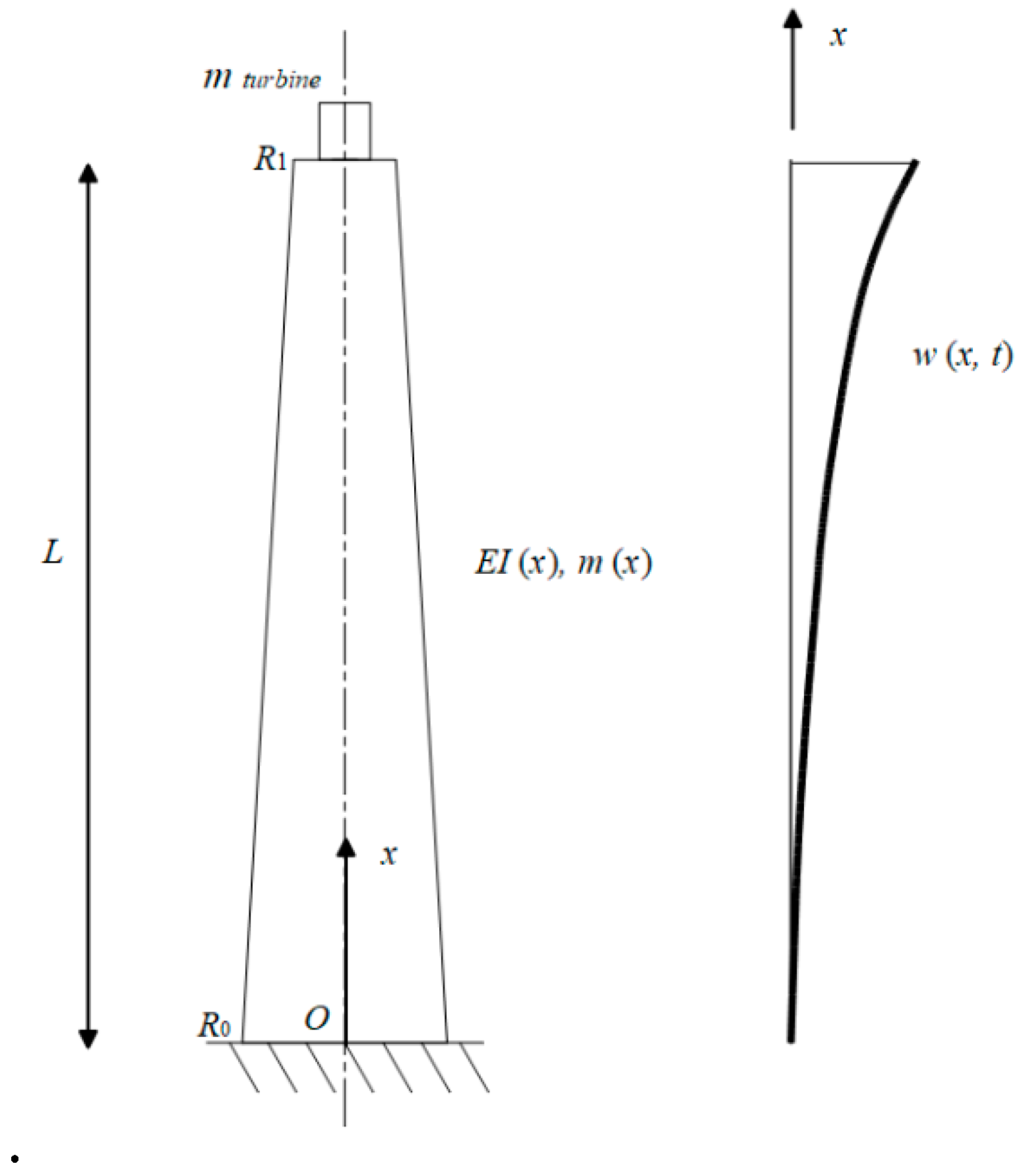
Figure 4.
Main parts of the (a) H-type and (b) hybrid VAWTs and (c) their MDOF model; (d) an H-type VAWT shaft cross-section and (e) hybrid VAWT shaft and inner blade cross-sections.
Figure 4.
Main parts of the (a) H-type and (b) hybrid VAWTs and (c) their MDOF model; (d) an H-type VAWT shaft cross-section and (e) hybrid VAWT shaft and inner blade cross-sections.
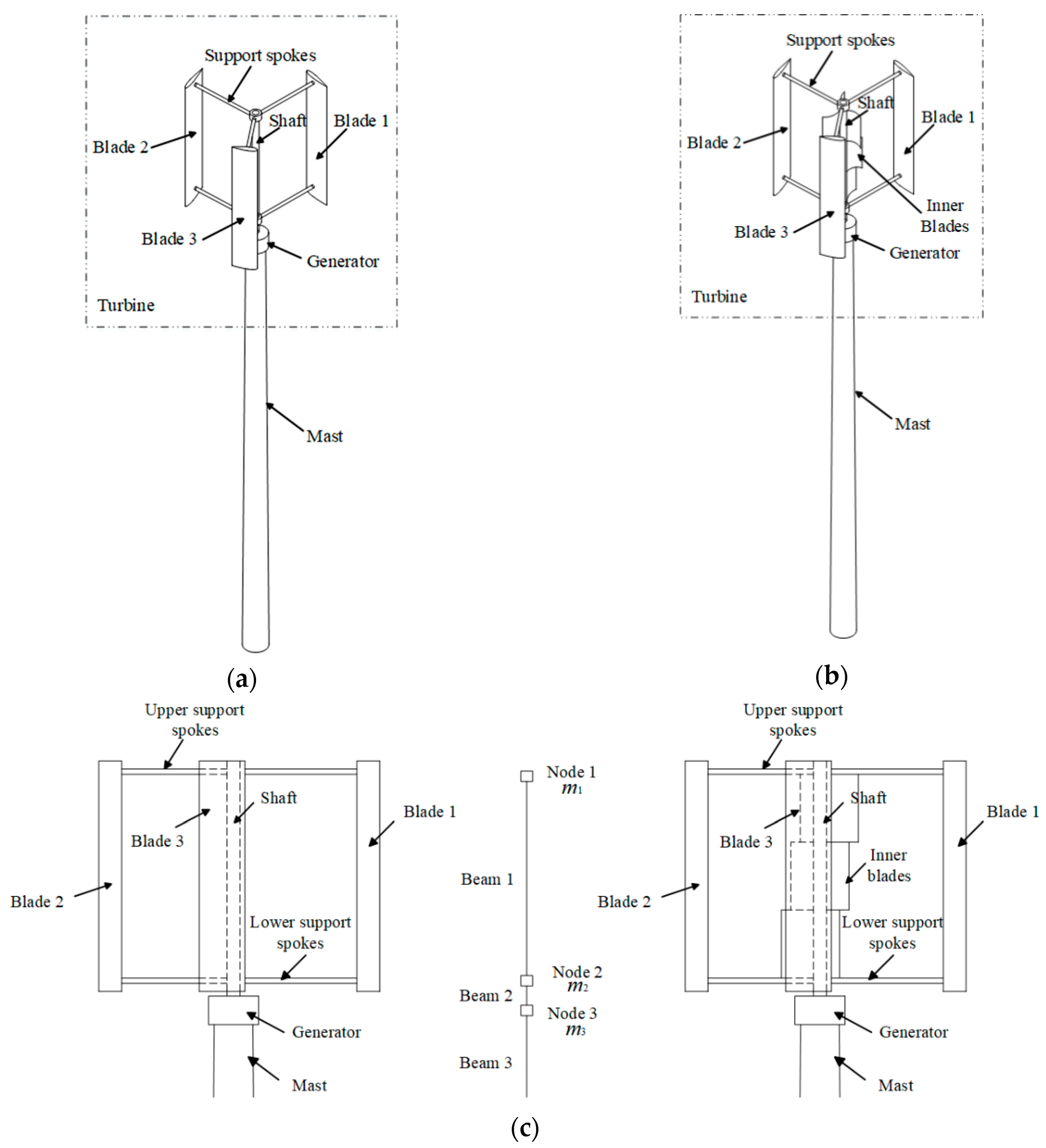
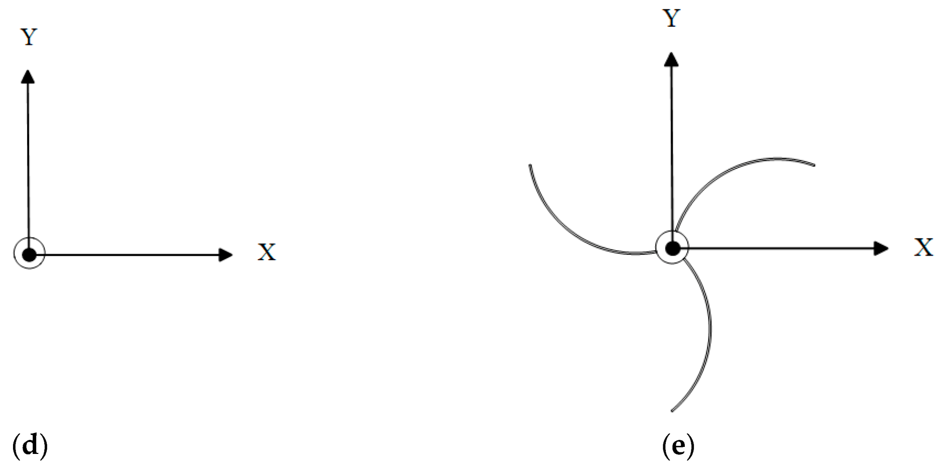
Figure 5.
Schematic of the MDOF model of the two VAWTs.
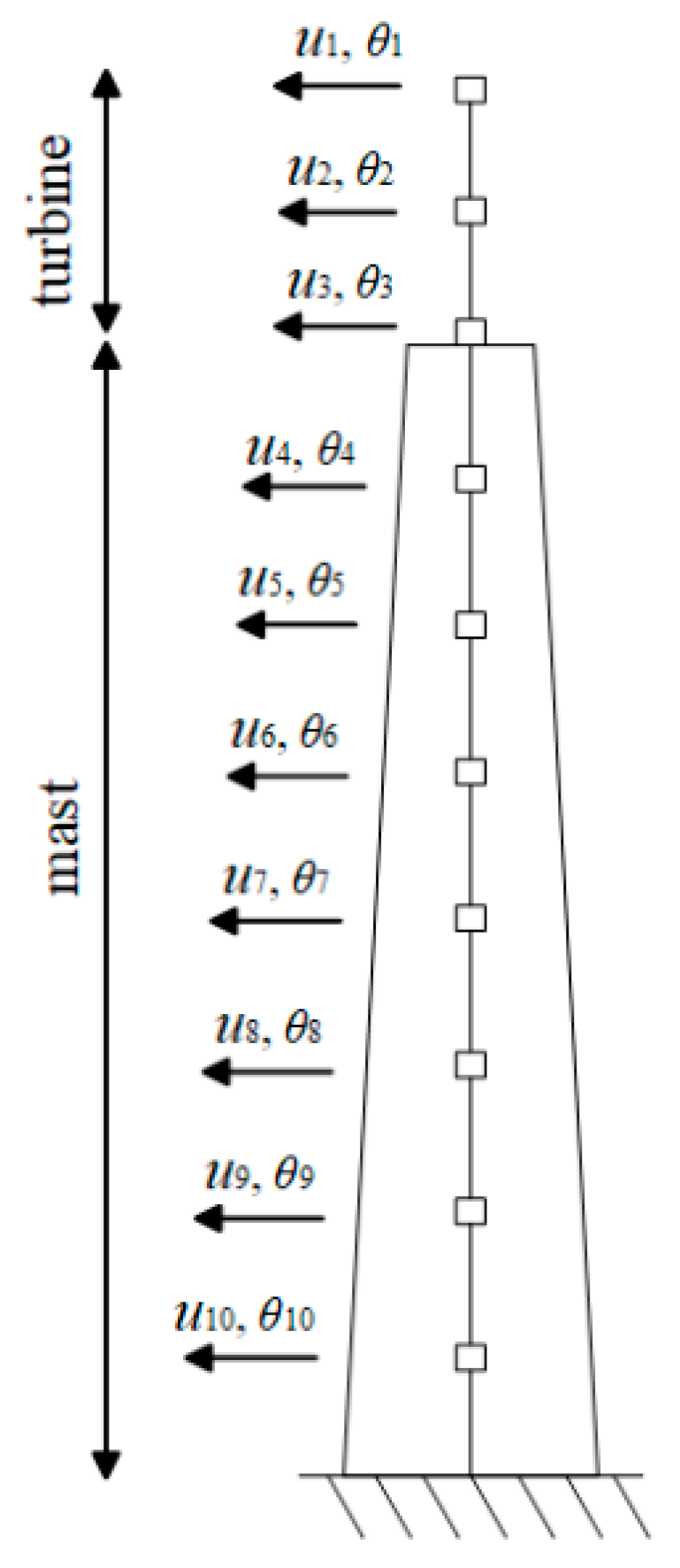
Figure 6.
Simpler MDOF model of the VAWTs with only three nodes.
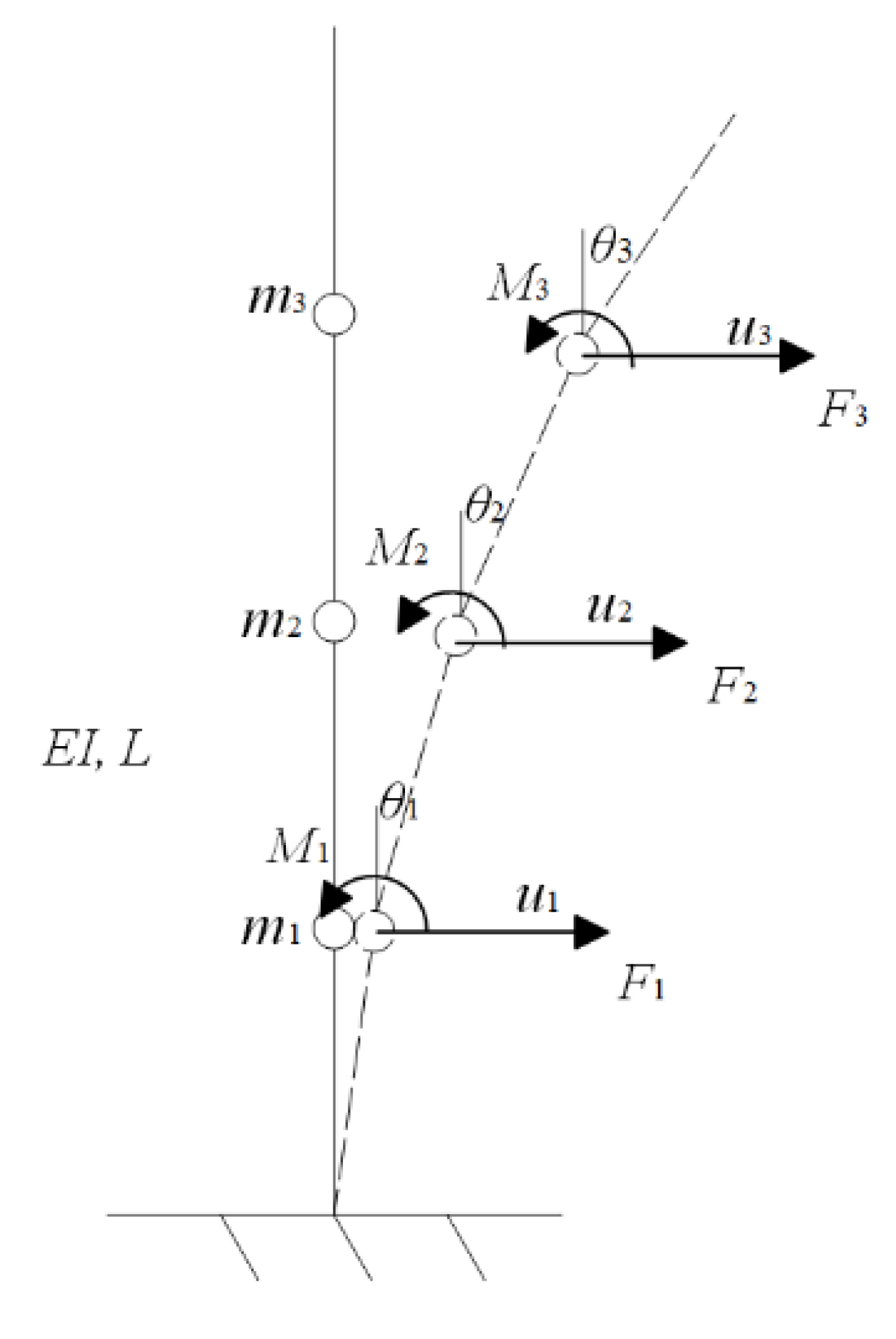
Figure 7.
Schematic of the two BEMs of the two VAWTs: (a) the mass of the mast is assigned at nodes of beam elements; and (b) the mass of the mast is assigned on beam elements.
Figure 7.
Schematic of the two BEMs of the two VAWTs: (a) the mass of the mast is assigned at nodes of beam elements; and (b) the mass of the mast is assigned on beam elements.
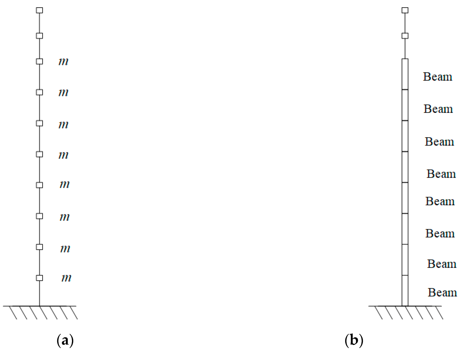
Figure 8.
Aerodynamic loads acting on different VAWT blades in X- and Y-directions: (a) H-type VAWT in the X-direction; (b) H-type VAWT in the Y-direction; (c) hybrid VAWT in the X-direction; and (d) hybrid VAWT in the Y-direction.
Figure 8.
Aerodynamic loads acting on different VAWT blades in X- and Y-directions: (a) H-type VAWT in the X-direction; (b) H-type VAWT in the Y-direction; (c) hybrid VAWT in the X-direction; and (d) hybrid VAWT in the Y-direction.
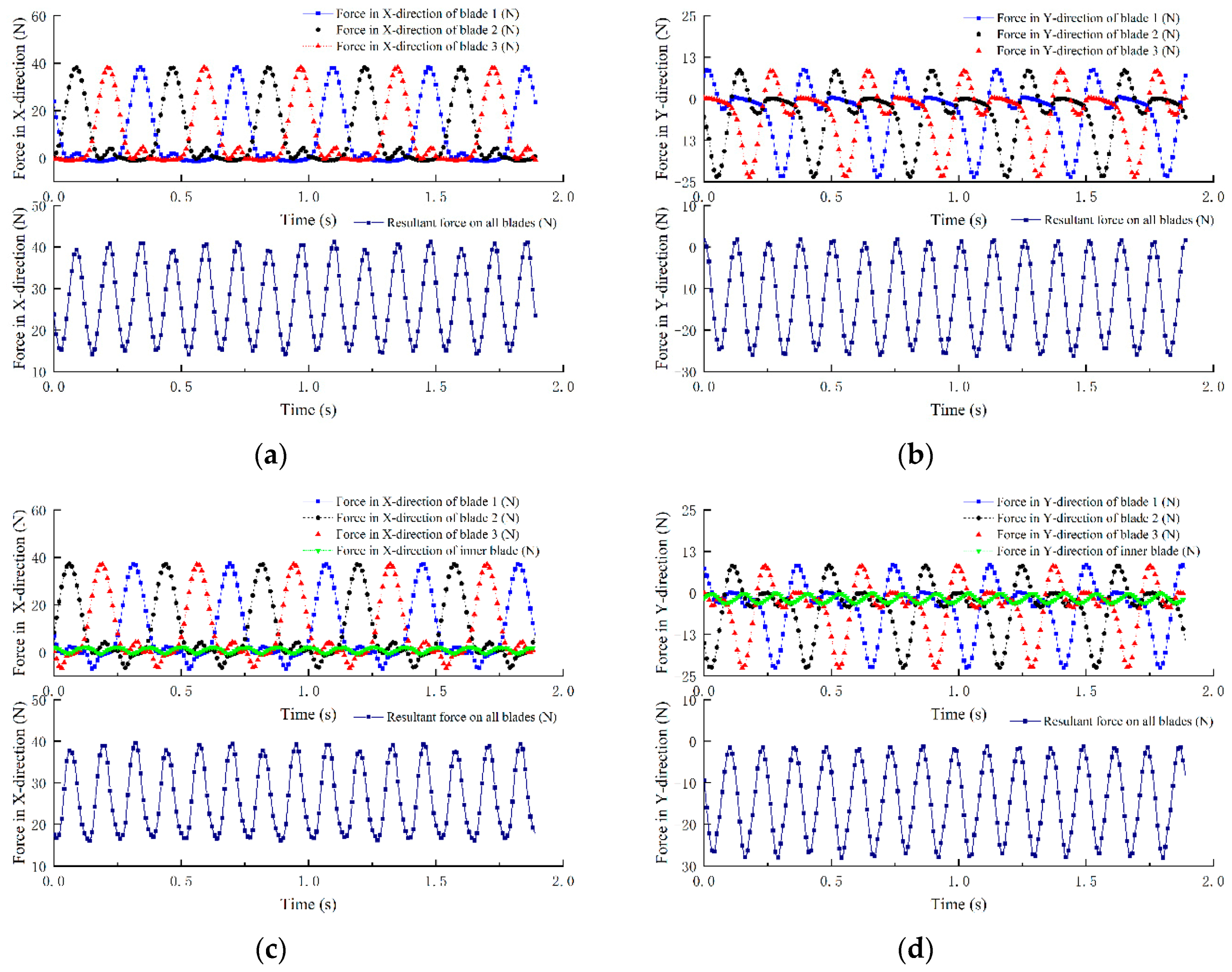
Figure 9.
Instantaneous vorticity fields around the (a) H-type and (b) hybrid VAWTs.
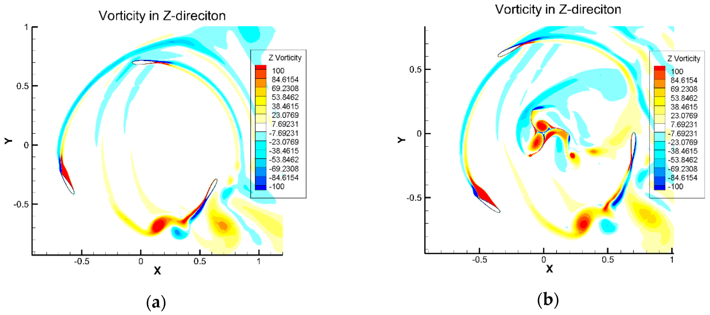
Figure 10.
(a) BEM and (b–d) the first three mode shapes of the 4 m-mast H-type VAWT in the X-Y plane: (b) the first mode shape with the natural frequency of 1.941 Hz, (c) the second mode shape with the natural frequency of 48.556 Hz, and (d) the third mode shape with the natural frequency of 150.54 Hz.

Figure 11.
(a) Amplitude-frequency responses of the 1 m-mast H-type and hybrid VAWTs in (a) X and (b) Y directions.
Figure 11.
(a) Amplitude-frequency responses of the 1 m-mast H-type and hybrid VAWTs in (a) X and (b) Y directions.
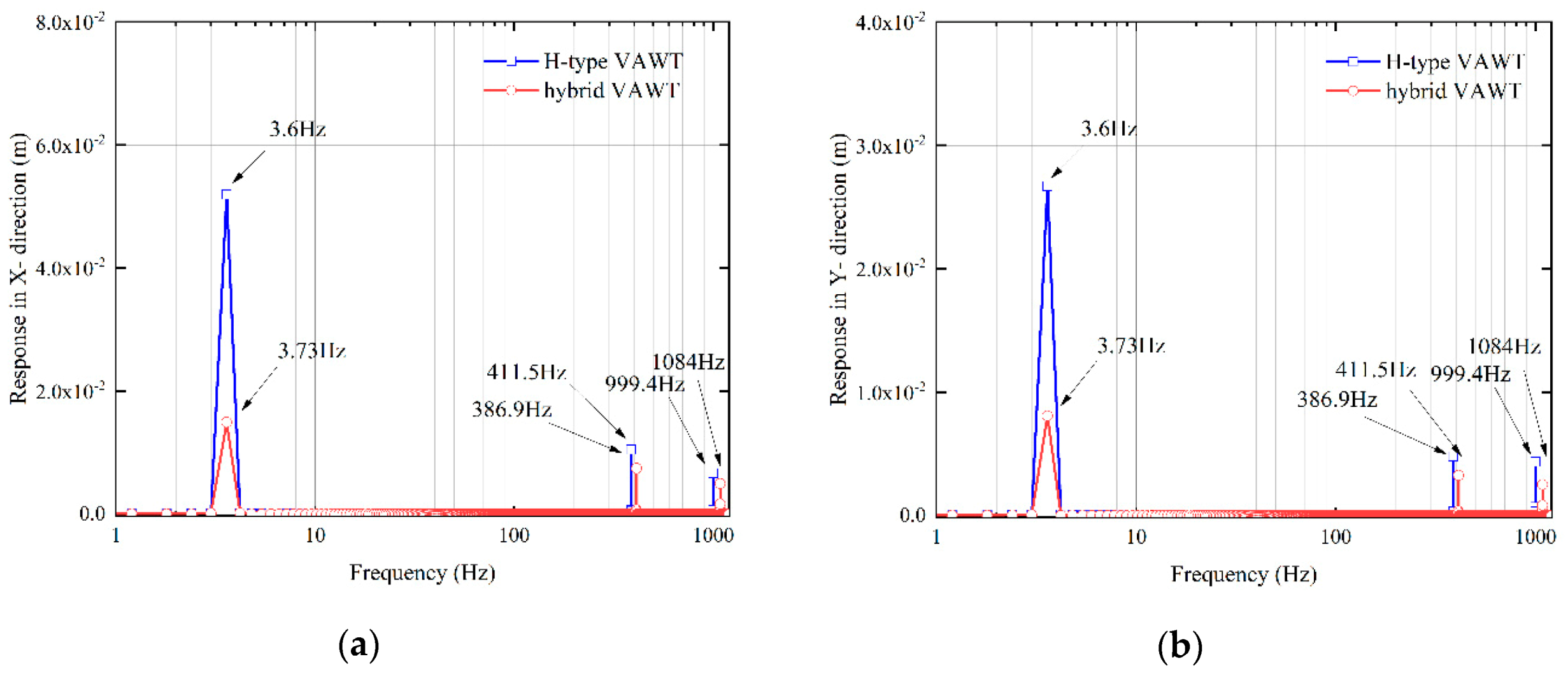
Figure 12.
(a) Amplitude-frequency responses of the 4 m-mast H-type and hybrid VAWTs in (a) X and (b) Y directions.
Figure 12.
(a) Amplitude-frequency responses of the 4 m-mast H-type and hybrid VAWTs in (a) X and (b) Y directions.
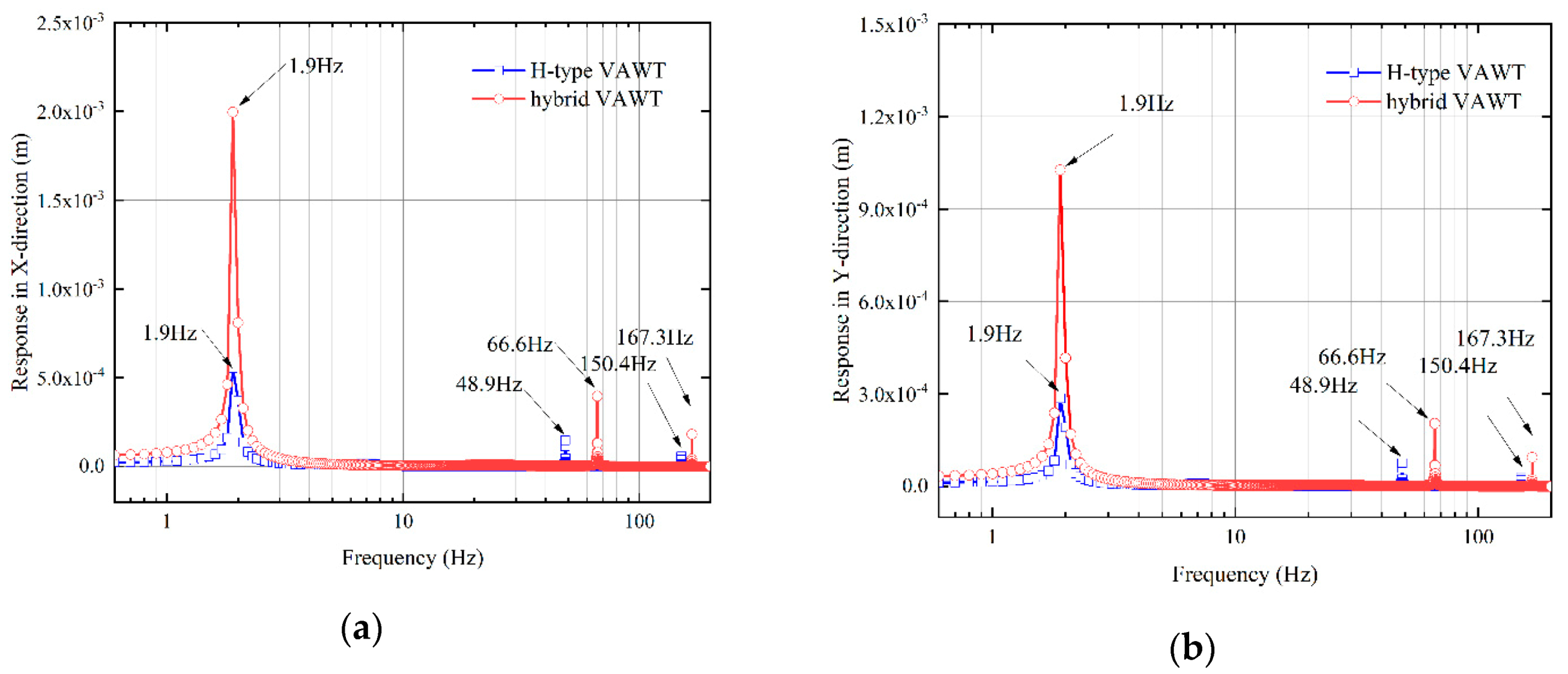
Figure 13.
Forced transient responses of the 1 m-mast H-type and hybrid VAWTs in (a) X- and (b) Y-directions, and their steady-state responses in the (c) X- and (d) Y-directions from 6.5 to 8.5 s.
Figure 13.
Forced transient responses of the 1 m-mast H-type and hybrid VAWTs in (a) X- and (b) Y-directions, and their steady-state responses in the (c) X- and (d) Y-directions from 6.5 to 8.5 s.

Figure 14.
Forced transient responses of the 4 m-mast H-type and hybrid VAWTs in (a) X- and (b) Y-directions, and their steady-state responses in the (c) X- and (d) Y-directions from 6.5 to 8.5 s.
Figure 14.
Forced transient responses of the 4 m-mast H-type and hybrid VAWTs in (a) X- and (b) Y-directions, and their steady-state responses in the (c) X- and (d) Y-directions from 6.5 to 8.5 s.
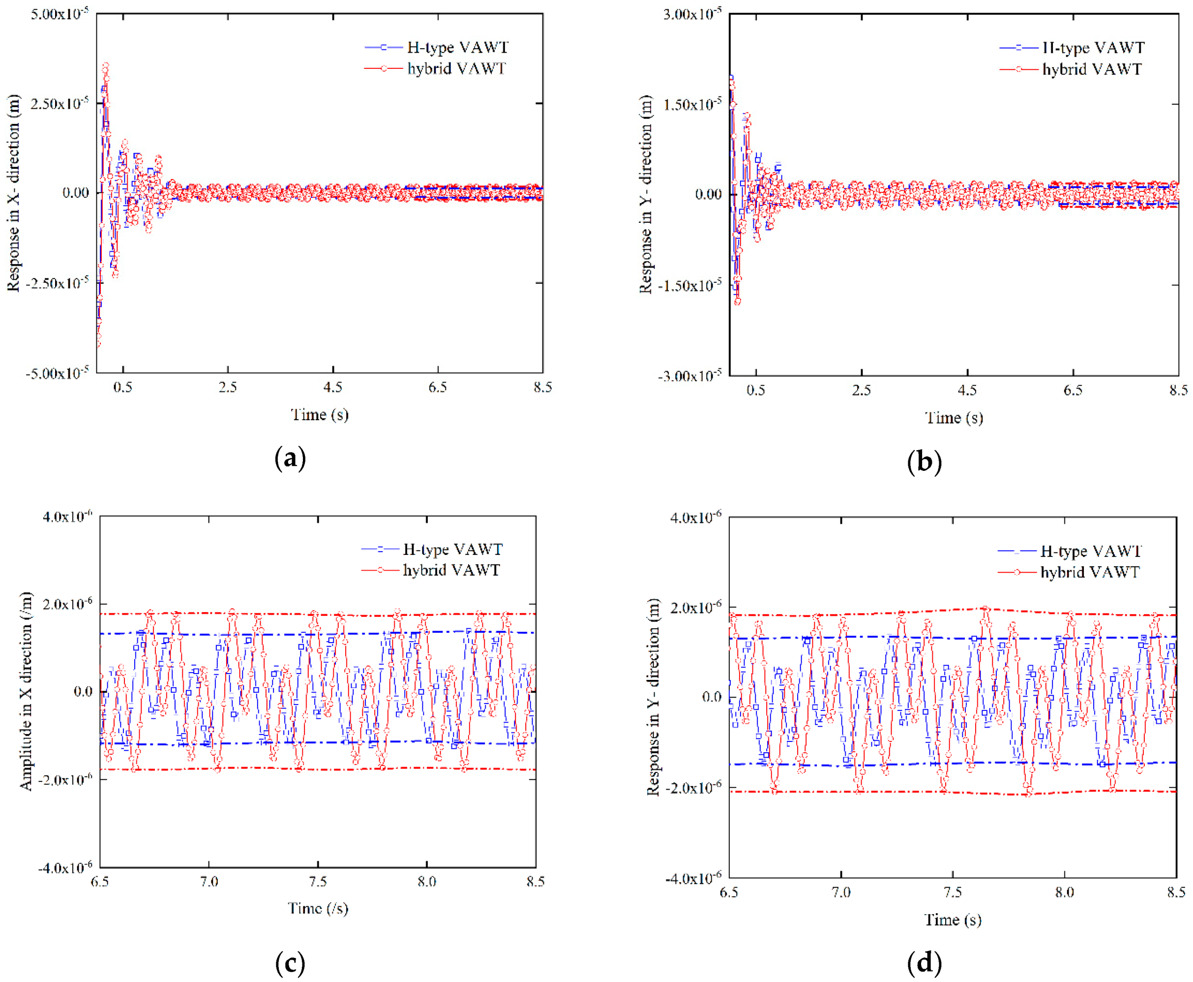
Figure 15.
First three mode shapes of the H-type VAWT from its SEM that correspond to its X-Y planar motion: (a) the first mode shape with the natural frequency 1.92 Hz; (b) the second mode shape with the natural frequency 50.2 Hz; and (c) the third mode shape with the natural frequency 154.1 Hz.
Figure 15.
First three mode shapes of the H-type VAWT from its SEM that correspond to its X-Y planar motion: (a) the first mode shape with the natural frequency 1.92 Hz; (b) the second mode shape with the natural frequency 50.2 Hz; and (c) the third mode shape with the natural frequency 154.1 Hz.
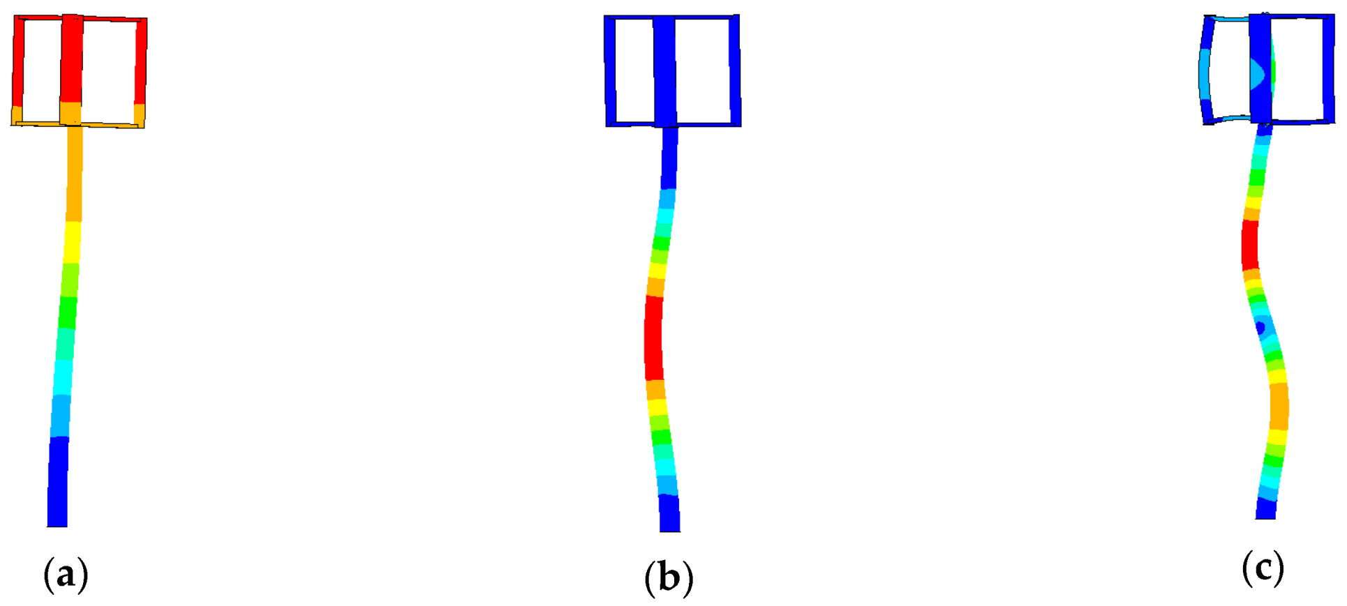
Figure 16.
First three mode shapes of the hybrid VAWT from its SEM that correspond to its X-Y planar motion: (a) the first mode shape with the natural frequency 1.90 Hz; (b) the second mode shape with the natural frequency 66.9 Hz; and (c) the third mode shape with the natural frequency 170.4 Hz.
Figure 16.
First three mode shapes of the hybrid VAWT from its SEM that correspond to its X-Y planar motion: (a) the first mode shape with the natural frequency 1.90 Hz; (b) the second mode shape with the natural frequency 66.9 Hz; and (c) the third mode shape with the natural frequency 170.4 Hz.
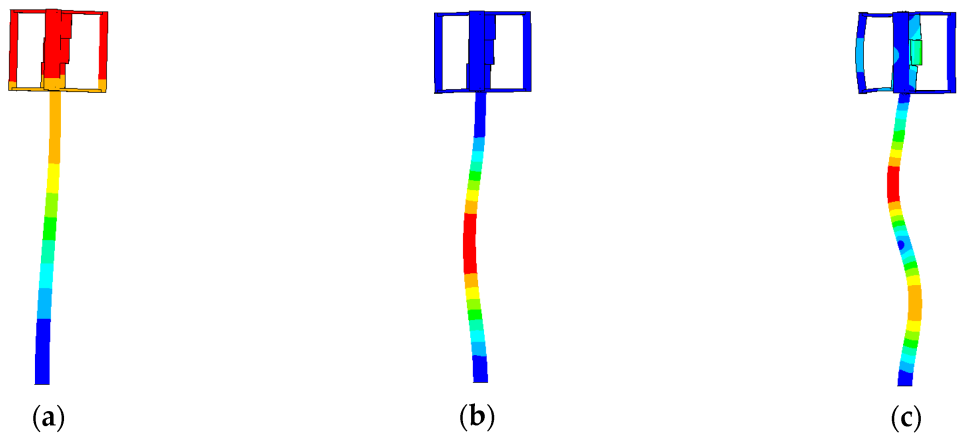
Figure 17.
Forced transient responses of the 1 m-mast H-type and hybrid VAWTs in (a) X- and (b) Y-directions, and their steady-state responses in the (c) X- and (d) Y-directions from 6.5 to 8.5 s.
Figure 17.
Forced transient responses of the 1 m-mast H-type and hybrid VAWTs in (a) X- and (b) Y-directions, and their steady-state responses in the (c) X- and (d) Y-directions from 6.5 to 8.5 s.
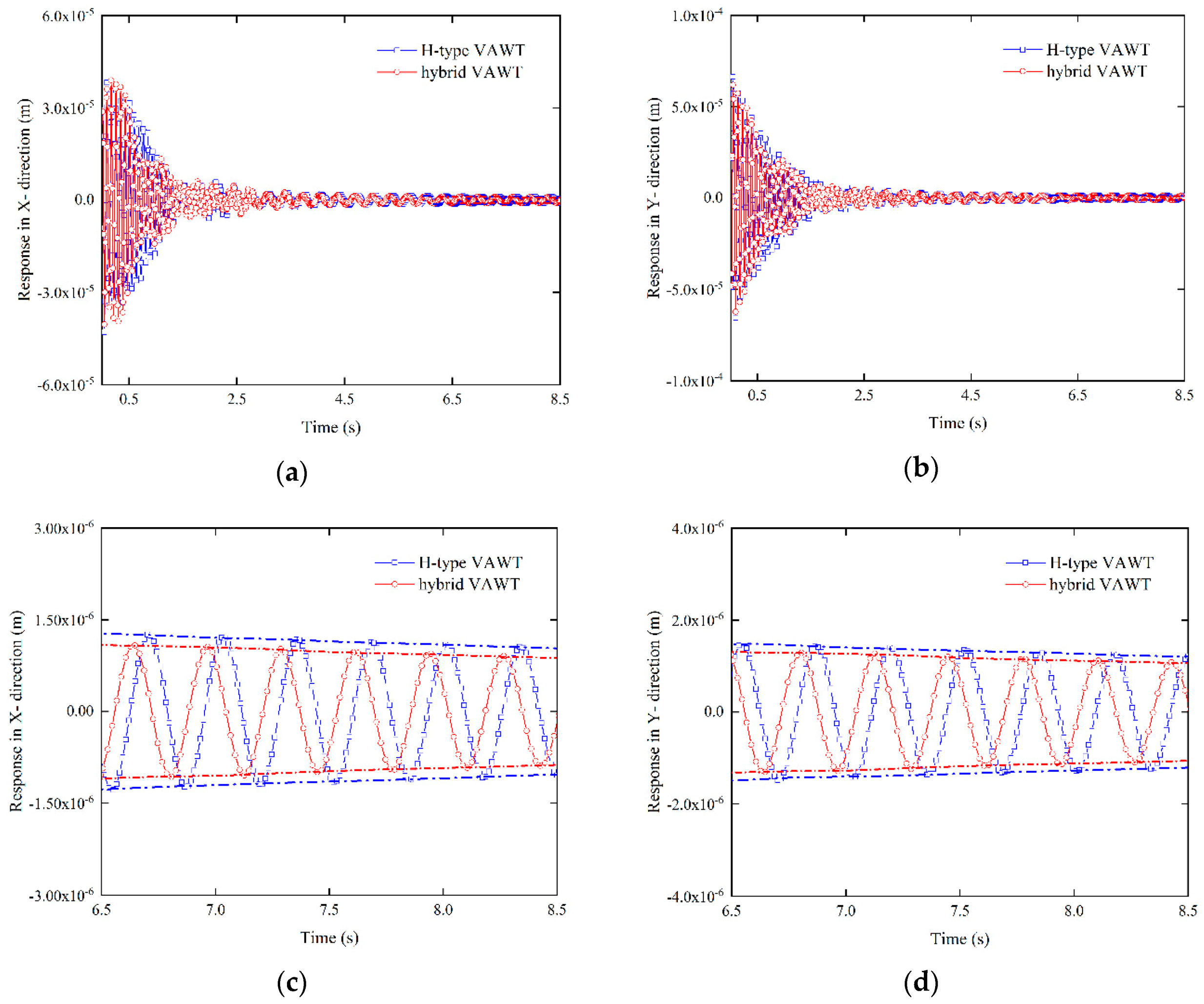
Figure 18.
Forced transient responses of the 4 m-mast H-type and hybrid VAWTs in (a) X- and (b) Y-directions, and their steady-state responses in the (c) X- and (d) Y-directions from 6.5 to 8.5 s.
Figure 18.
Forced transient responses of the 4 m-mast H-type and hybrid VAWTs in (a) X- and (b) Y-directions, and their steady-state responses in the (c) X- and (d) Y-directions from 6.5 to 8.5 s.

Figure 19.
Aerodynamic loads acting on blades of the (a) H-type and (c) hybrid VAWTs in the X-direction and their dominant excitation frequencies for the (b) H-type and (d) hybrid VAWTs.
Figure 19.
Aerodynamic loads acting on blades of the (a) H-type and (c) hybrid VAWTs in the X-direction and their dominant excitation frequencies for the (b) H-type and (d) hybrid VAWTs.

Figure 20.
Aerodynamic loads acting on blades of the (a) H-type and (c) hybrid VAWTs in the Y-direction and their dominant excitation frequencies for the (b) H-type and (d) hybrid VAWTs.
Figure 20.
Aerodynamic loads acting on blades of the (a) H-type and (c) hybrid VAWTs in the Y-direction and their dominant excitation frequencies for the (b) H-type and (d) hybrid VAWTs.


Figure 21.
Moments produced by aerodynamic loads in X- and Y-directions along the Z-direction on the (a) H-type and (c) hybrid VAWTs and their dominant excitation frequencies for the (b) H-type and (d) hybrid VAWTs.
Figure 21.
Moments produced by aerodynamic loads in X- and Y-directions along the Z-direction on the (a) H-type and (c) hybrid VAWTs and their dominant excitation frequencies for the (b) H-type and (d) hybrid VAWTs.

Figure 22.
Aerodynamic moments and output powers of the H-type and hybrid VAWTs in one rotation period: (a,b) output powers from outer blades of the H-type and hybrid VAWTs, respectively; (c,d) output powers from inner blades of the H-type and hybrid VAWTs, respectively; and (e,f) output powers from both outer and inner blades of the H-type and hybrid VAWTs, respectively.


Table 1.
Mass and stiffness values of the simplified MDOF turbine model.
| Model Part | Mass | Stiffness | Value | |||
|---|---|---|---|---|---|---|
| H-type Mass | Hybrid Mass | H-type Stiffness | Hybrid Stiffness | |||
| Node 1 | Upper spokes + 50% of blades and shaft | / | 44.9 | 50.2 | 0 | 0 |
| Beam 1 | No mass | Shaft between nodes 1 and 2 | 0 | 0 | ||
| Node 2 | Lower spokes + 50% of blades and shaft | / | 44.9 | 50.2 | 0 | 0 |
| Beam 2 | No mass | Shaft between nodes 2 and 3 | 0 | 0 | ||
| Node 3 | Generator | / | 604.5 | 604.5 | 0 | 0 |
Table 2.
Summary of parameters in CFD simulation.
| Input Variable | Value/Setting |
|---|---|
| Turbulence Model | Spalart-Allmaras model |
| Pressure-velocity coupling | SIMPLE |
| Spatial discretization scheme | Second-order upwind |
| Time integration | Second-order implicit |
| Inlet turbulence viscosity ratio | 10 |
| Convergence criterion for residuals | 10−5 |
| Reynolds number | 4.9 × 10⁵ |
Table 3.
Mast parameters of the SDOF model of the two VAWTs.
| Parameter | Value |
|---|---|
| Mast height | |
| Outer diameter of the cross-section | |
| Mast thickness | |
| Inertia of the cross-section | |
| Mast mass | |
| Turbine mass for the H-type VAWT | |
| Turbine mass for the hybrid VAWT | |
| Young’s modulus | |
| Material density of steel |
Table 4.
Natural frequencies of the SDOF model of the H-type and hybrid VAWTs with different mast parameters.
Table 4.
Natural frequencies of the SDOF model of the H-type and hybrid VAWTs with different mast parameters.
| Case | (Hz) | (Hz) | ||||||
|---|---|---|---|---|---|---|---|---|
| Case 1 | 1 | 88.9 | 66.7 | 5 | 0.25 | 1.38 × 10⁶ | 3.87 | 3.98 |
| Case 2 | 2 | 133 | 100 | 5 | 0.25 | 4.62 × 10⁶ | 2.96 | 2.99 |
| Case 3 | 4 | 200 | 150 | 5 | 0.25 | 1.57 × 10⁷ | 2.07 | 2.05 |
Table 5.
Geometric properties of the MDOF model of the H-type and hybrid VAWTs.
| Element No. | 1 | 2 | 3 | 4 | 5 | 6 | 7 | 8 | 9 | 10 | |
|---|---|---|---|---|---|---|---|---|---|---|---|
| 1 m | 40 | 40 | 66.7 | 69.8 | 72.9 | 76.0 | 79.1 | 82.2 | 85.3 | 88.9 | |
| 20 | 20 | 5 | 5 | 5 | 5 | 5 | 5 | 5 | 5 | ||
| 900 | 100 | 125 | 125 | 125 | 125 | 125 | 125 | 125 | 125 | ||
| H-type m (kg) | 44.9 | 44.9 | 604.5 | 1.3 | 1.3 | 1.3 | 1.3 | 1.3 | 1.3 | 1.3 | |
| Hybrid m (kg) | 50.2 | 50.2 | 604.5 | 1.3 | 1.3 | 1.3 | 1.3 | 1.3 | 1.3 | 1.3 | |
| 2 m | 40 | 40 | 100 | 105 | 109 | 114 | 119 | 123 | 128 | 133 | |
| 20 | 20 | 5 | 5 | 5 | 5 | 5 | 5 | 5 | 5 | ||
| 900 | 100 | 250 | 250 | 250 | 250 | 250 | 250 | 250 | 250 | ||
| H-type m (kg) | 44.9 | 44.9 | 604.5 | 3.9 | 3.9 | 3.9 | 3.9 | 3.9 | 3.9 | 3.9 | |
| Hybrid m (kg) | 50.2 | 50.2 | 604.5 | 3.9 | 3.9 | 3.9 | 3.9 | 3.9 | 3.9 | 3.9 | |
| 4 m | 40 | 40 | 150 | 157 | 164 | 171 | 178 | 185 | 192 | 200 | |
| 20 | 20 | 5 | 5 | 5 | 5 | 5 | 5 | 5 | 5 | ||
| 900 | 100 | 500 | 500 | 500 | 500 | 500 | 500 | 500 | 500 | ||
| H-type m (kg) | 44.9 | 44.9 | 604.5 | 12.0 | 12.0 | 12.0 | 12.0 | 12.0 | 12.0 | 12.0 | |
| Hybrid m (kg) | 50.2 | 50.2 | 604.5 | 12.0 | 12.0 | 12.0 | 12.0 | 12.0 | 12.0 | 12.0 | |
Table 6.
First three natural frequencies of the SDOF and MDOF models of the H-type VAWT.
| Mast Height | Mode | SDOF | MDOF | Difference |
|---|---|---|---|---|
| 1 m | 1 | 3.87 | 3.73 | 3.67% |
| 2 | 399.4 | |||
| 3 | 1004 | |||
| 2 m | 1 | 2.96 | 2.87 | 3.12% |
| 2 | 145.1 | |||
| 3 | 399.2 | |||
| 4 m | 1 | 2.07 | 2.00 | 3.50% |
| 2 | 50.0 | |||
| 3 | 150.5 |
Table 7.
First natural frequencies of the SDOF and MDOF models of the hybrid VAWT.
| Mast Height | Mode | SDOF | MDOF | Difference |
|---|---|---|---|---|
| 1 m | 1 | 3.98 | 3.85 | 3.25% |
| 2 | 412.4 | |||
| 3 | 1105 | |||
| 2 m | 1 | 2.99 | 2.89 | 3.53% |
| 2 | 170.5 | |||
| 3 | 417.9 | |||
| 4 m | 1 | 2.05 | 1.99 | 3.02% |
| 2 | 69.0 | |||
| 3 | 166.8 |
Table 8.
First three natural frequencies of the MDOF model and BEM of the H-type VAWT with different mast heights.
Table 8.
First three natural frequencies of the MDOF model and BEM of the H-type VAWT with different mast heights.
| Mast Height | Mode | MDOF | BEM | Difference |
|---|---|---|---|---|
| 1 m | 1 | 3.73 | 3.60 | 3.54% |
| 2 | 399.4 | 386.9 | 3.22% | |
| 3 | 1004 | 999.4 | 0.49% | |
| 2 m | 1 | 2.87 | 2.78 | 3.09% |
| 2 | 145.1 | 141.0 | 2.88% | |
| 3 | 399.2 | 398.7 | 0.13% | |
| 4 m | 1 | 2.00 | 1.94 | 3.09% |
| 2 | 50.0 | 48.6 | 2.88% | |
| 3 | 150.5 | 150.3 | 0.13% |
Table 9.
First three natural frequencies of the MDOF model and BEM of the hybrid VAWT with different mast heights.
Table 9.
First three natural frequencies of the MDOF model and BEM of the hybrid VAWT with different mast heights.
| Mast Height | Mode | MDOF | BEM | Difference |
|---|---|---|---|---|
| 1 m | 1 | 3.85 | 3.73 | 3.16% |
| 2 | 412.4 | 411.5 | 0.22% | |
| 3 | 1105 | 1084 | 1.92% | |
| 2 m | 1 | 2.89 | 2.80 | 3.11% |
| 2 | 170.5 | 164.1 | 3.92% | |
| 3 | 417.9 | 417.4 | 0.12% | |
| 4 m | 1 | 1.99 | 1.93 | 3.11% |
| 2 | 69.0 | 66.4 | 3.92% | |
| 3 | 166.8 | 167.0 | 0.12% |
Table 10.
Comparison of the maximum steady-state response amplitudes of the 1 m-mast H-type and hybrid VAWTs in X- and Y-directions.
Table 10.
Comparison of the maximum steady-state response amplitudes of the 1 m-mast H-type and hybrid VAWTs in X- and Y-directions.
| Direction | H-type VAWT (m) | Hybrid VAWT (m) | Difference |
|---|---|---|---|
| X-direction | 26.9% | ||
| Y-direction | 22.6% | ||
| Difference | 11.1% | 14.9% |
Table 11.
Comparison of the maximum steady-state response amplitudes of the 4 m-mast H-type and hybrid VAWTs in X- and Y-directions.
Table 11.
Comparison of the maximum steady-state response amplitudes of the 4 m-mast H-type and hybrid VAWTs in X- and Y-directions.
| Direction | H-type VAWT (m) | Hybrid VAWT (m) | Difference |
|---|---|---|---|
| X-direction | 24.6% | ||
| Y-direction | 31.6% | ||
| Difference | 5.76% | 11.8% |
Table 12.
Comparison of the first three natural frequencies of the 1 m-mast H-type and hybrid VAWTs from their SEMs that correspond to their X-Y planar motions and the first natural frequencies of the two VAWTs from their BEM.
Table 12.
Comparison of the first three natural frequencies of the 1 m-mast H-type and hybrid VAWTs from their SEMs that correspond to their X-Y planar motions and the first natural frequencies of the two VAWTs from their BEM.
| Mode | H-type VAWT BEM (Hz) | H-type VAWT SEM (Hz) | Difference | Hybrid VAWT BEM (Hz) | Hybrid VAWT SEM (Hz) | Difference |
|---|---|---|---|---|---|---|
| 1 | 3.60 | 3.65 | 1.39% | 3.73 | 3.79 | 1.61% |
| 2 | 386.9 | 402.5 | 4.03% | 411.5 | 429.2 | 4.30% |
| 3 | 999.4 | 1032 | 3.26% | 1084 | 1121 | 3.41% |
Table 13.
Comparison of the first three natural frequencies of the 4 m-mast H-type and hybrid VAWTs from their SEMs that correspond to their X-Y planar motions and the first natural frequencies of the two VAWTs from their BEM.
Table 13.
Comparison of the first three natural frequencies of the 4 m-mast H-type and hybrid VAWTs from their SEMs that correspond to their X-Y planar motions and the first natural frequencies of the two VAWTs from their BEM.
| Mode | H-type VAWT BEM (Hz) | H-type VAWT SEM (Hz) | Difference | Hybrid VAWT BEM (Hz) | Hybrid VAWT SEM (Hz) | Difference |
|---|---|---|---|---|---|---|
| 1 | 1.94 | 1.92 | 1.04% | 1.93 | 1.90 | 1.58% |
| 2 | 48.6 | 50.2 | 3.31% | 64.4 | 66.9 | 3.97% |
| 3 | 150.3 | 154.1 | 2.53% | 167.0 | 170.4 | 2.02% |
Table 14.
Comparison of the maximum steady-state response amplitudes of the 1 m-mast H-type and hybrid VAWTs in X- and Y-directions from their SEMs.
Table 14.
Comparison of the maximum steady-state response amplitudes of the 1 m-mast H-type and hybrid VAWTs in X- and Y-directions from their SEMs.
| Mode | H-type VAWT (m) | Hybrid VAWT (m) | Difference |
|---|---|---|---|
| X-direction | 23.8% | ||
| Y-direction | 20.5% | ||
| Difference | 17.4% | 20.1% |
Table 15.
Comparison of the maximum steady-state response amplitudes of the 4 m-mast H-type and hybrid VAWTs in X- and Y-directions from their SEMs.
Table 15.
Comparison of the maximum steady-state response amplitudes of the 4 m-mast H-type and hybrid VAWTs in X- and Y-directions from their SEMs.
| Mode | H-type VAWT (m) | Hybrid VAWT (m) | Difference |
|---|---|---|---|
| X-direction | 22.8% | ||
| Y-direction | 24.3% | ||
| Difference | 13.8% | 15.3% |
Publisher’s Note: MDPI stays neutral with regard to jurisdictional claims in published maps and institutional affiliations. |
© 2020 by the authors. Licensee MDPI, Basel, Switzerland. This article is an open access article distributed under the terms and conditions of the Creative Commons Attribution (CC BY) license (http://creativecommons.org/licenses/by/4.0/).
Share and Cite
MDPI and ACS Style
Tong, M.; Zhu, W.; Zhao, X.; Yu, M.; Liu, K.; Li, G. Free and Forced Vibration Analysis of H-type and Hybrid Vertical-Axis Wind Turbines. Energies 2020, 13, 6747. https://doi.org/10.3390/en13246747
AMA Style
Tong M, Zhu W, Zhao X, Yu M, Liu K, Li G. Free and Forced Vibration Analysis of H-type and Hybrid Vertical-Axis Wind Turbines. Energies. 2020; 13(24):6747. https://doi.org/10.3390/en13246747
Chicago/Turabian StyleTong, Minhui, Weidong Zhu, Xiang Zhao, Meilin Yu, Kan Liu, and Gang Li. 2020. "Free and Forced Vibration Analysis of H-type and Hybrid Vertical-Axis Wind Turbines" Energies 13, no. 24: 6747. https://doi.org/10.3390/en13246747
Note that from the first issue of 2016, this journal uses article numbers instead of page numbers. See further details here.