Effect of EGR and Fuel Injection Strategies on the Heavy-Duty Diesel Engine Emission Performance under Transient Operation

1
The State Key Laboratory of Automotive Simulation and Control, Jilin University, Changchun 130025, China
2
SAIC, Shanghai 201201, China
3
Shanghai Volkswagen Automotive Co., Ltd., Shanghai 201805, China
*
Author to whom correspondence should be addressed.
Energies 2020, 13(3), 566; https://doi.org/10.3390/en13030566
Submission received: 12 November 2019
/
Revised: 15 January 2020
/
Accepted: 15 January 2020
/
Published: 24 January 2020
Abstract
:To reduce the smoke and nitrogen oxide (NOx) emissions; a detailed study concerned with exhaust gas recirculation (EGR) and diesel injection strategy was conducted on a two-stage series turbocharging diesel engine under transient operating condition. One transient process based on the constant speed of 1650 r/min and load increases linearly from 10% to 100% within 5 s was tested in this study. The effect of the EGR valve control strategy on engine transient performance was examined. The results show that better air-fuel mixing quality can be obtained with the optimized the EGR valve open loop control strategy and the smoke opacity peak decreased more than 64%. Under the EGR valve close loop control strategy; the smoke opacity peak was lower than with open loop control strategy; but higher than without EGR. The effect of fuel injection strategy on engine transient performance was examined with the EGR valve close loop control. The results show that sectional-stage rail pressure (SSRP) strategy (increasing injection pressure from a turning point load to 100% load) and optimizing fuel injection timing can improve the engine emission performance. The satisfactory results can be obtained with lower NOx (382 ppm) emissions and the smoke opacity peak (3.8%), when the turning point load is set to 60% with the injection timing delay 6° CA.
1. Introduction
Diesel vehicles operate in transient conditions in most cases. The transient feature is the delay of boundary condition response compared to steady state [1,2,3,4], which leads to deterioration of fuel economy and pollutant emission [5,6,7,8]. In addition, in order to meet the requirements of increasingly stringent emissions regulations, many transient performances and optimization methods have been studied in recent years. The reduction of oxygen concentration caused by air intake delay decreases the nitrogen oxide (NOx) emission. Furthermore, the lack of oxygen leads to an increase of the goal equivalence ratio which causes a poor smoke emission [9,10,11,12,13]. Filipi et al. [14] claimed soot emission increases rapidly when the load has a sudden increase from idle state. Moreover, the more quickly the load increases, the bigger the average particulate size is. Glewen et al. [15] found the main reason of deviation between transient performance and steady performance in light-duty diesel engine is the in-cylinder temperature of intake valve close timing and the extra oxygen concentration in exhaust gas recirculation (EGR).
Two-stage series turbocharging can expand the range of air inflow at the designed speed, so it is suitable to solve the problem of air supply delay in theory. Choi et al. claimed the performance of tandem type two-stage series turbocharging is better than the variable geometry turbocharger (VGT) [16]. In addition, the tandem type two-stage series turbocharging can not only expend the power threshold of the diesel engine, but promote the torque in early-stage transient process. Winkler et al. [17] used the twin-entry turbocharger as the high pressure stage and VGT as the low pressure stage respectively in the two-stage series turbocharging system, which obtained better transient response performance and low smoke emission. Furthermore, when we maintained the full opening of VGT during the transient process, the speed of the high pressure stage turbine could be elevated.
From the perspective of injection parameters, Raghu et al. [18] studied the effect of injection pressure on the spray state through high-speed imaging, during which they found the injection pressure has a big impact on spray pattern (the spray cone angle, spray tip penetration, spraying area). The data displayed that when the injection pressure increases from 180 bar to 240 bar, the droplet size decreases nearly 60%. Therefore, the fuel atomization state and air-fuel mixing efficiency is improved. Eagle et al. researched the transient performance of spray in high injection pressure by constant volume combustion bomb and high-speed imaging [19]. The result of which showed that as the injection pressure increases from 1000 bar to 2000 bar, the spray broken time shortens about 45%. In addition, at early spray stage, the nozzle fluctuates significantly. Tamaki et al. and Sun et al. found the cavitation can accelerate the speed up atomization [20,21]. Octavio et al. obtained the data of air, evaporation of fuel and combustion products by a zero-dimensional thermodynamics diagnosis model and successfully described the transient combustion performance. The strategy has a great potential in close loop control field. Agarwal et al. claimed the injection pressure and injection timing are important factors that affect the performance of combustion and pollution. The test on a signal cylinder diesel engine showed a bigger injection pressure (1000 bar) or an earlier injection timing cause a large combustion cycle fluctuation. However, due to the extension of combustion duration, smoke emission decreases. The emission performance and fuel economy is better by combining a smaller injection pressure and earlier injection timing [22,23,24].
In the field of transient EGR research, Hebbar et al. concluded that EGR is an effective measure to reduce NOx emissions, but due to the deterioration of combustion caused by the EGR [25], hydrocarbon (HC)/ carbon monoxide (CO) emissions are higher. Park et al. and Heuwetter et al. and Nam et al. discussed the effect of the selection about the EGR circuit and try method on fuel economy and smoke emission [26,27,28]. The result showed that the response of the high pressure stage is quicker. Moreover, the differential pressure has little effect on the low pressure stage, so the EGR ratio is not easy to overshoot. Serrano et al. found that if the EGR valve opens quickly, the EGR ratio overshoots and causes smoke emission increasing [29]. Therefore, the strategy to set the EGR valve opens step by step and is important for controlling the EGR ratio and smoke emission. Wang et al. declared the combustion process can obtain both long premix time and low combustion temperature by delaying the injection timing and using a cool EGR, thereby guaranteeing low emissions of particulate matter (PM) and NOx [30]. Darlington et al. developed an air-path model to observe the gas component in-cylinder [31]. NOx emission could be reduced when they kept the burned fraction above threshold by controlling the EGR valve position. Furthermore, the soot formation was reduced by restricting the fuel quantity. Jia et al. realized the premix and low temperature combustion by advancing the injection timing and increasing the EGR ratio, thus getting a compromise among NOx, PM and brake specific fuel consumption (BSFC) [32]. Jung et al. achieved the combustion mode of premixed charge compression ignition (PCCI) by combining 50% ethanol mixed fuel and a 20% EGR ratio [33]. Therefore, the emissions of PM and NOx are limited.
The purpose of our research is to restrain the deterioration of smoke emission. The experiment was performed on a two-stage series turbocharging heavy-duty diesel engine with high pressure common rail, which was under the transient processing in which speed was kept at 1650 r/min, and the load was linearly increased from 10% to 100% within 5 s. Firstly, the optimization methods of the EGR valve open loop control on diesel transient performance were studied. Secondly, the effect of the EGR valve close loop control on transient performance was researched. Finally, in the basis of close loop control based on exhaust oxygen concentration, the optimization methods of diesel transient performance by combining the sectional-stage rail pressure (SSRP) strategies and full-stage injection timing (FSIT) strategies were continually studied.
2. Experimental Work
2.1. Experimental Setup
Primarily, Figure 1 shows a schematic diagram of the measurement and control system in the experiment. As shown in Figure 1, a high-pressure EGR was selected for the experiment. First, the exhaust gas is extracted before the high turbine (turbocharged, that is, increased air intake). The exhaust then passes through an EGR cooling unit (to cool the exhaust) and an EGR valve (to control the exhaust flow). Finally, the exhaust is directed behind the compressor.
As shown in Table 1, the test engine was equipped with a high-pressure common rail injection system and a two-stage series turbocharging (HOLSET400, Hunan TYEN Machinery Co., Ltd, Hengyang, Hunan Province, China). And Table 2 lists the main instruments and accuracy in the transient measurement and control process. During the experiment, we use high-response sensors and high-speed analog-to-digital converter (ADC) acquisition cards (milliseconds) to collect inlet and outlet speed, torque, temperature and pressure. On a common rail platform, the final control signal for the state of the diesel engine is the throttle voltage. Furthermore, based on the advantage of single chip with high response rate and accuracy, the topical transient process can be reproduced.
The EGR rate is calculated by EGR5230 (Engine Control and Monitoring, Los Altos, CA, USA) in the experiment, the calculation method of which is similar to that of traditional CO2 tracer. The EGR5230 analyzer calculates the EGR rate by directly measuring the amount of oxygen, oxides, and pressure in the engine’s intake and exhaust. We use O2 volume concentration to calculate the EGR rate by EGR5230. At the same time, the EGR5230 has automatic calibration function which can guarantee the calculation response rate. The equation of EGR rate is shown as follows:
where (O2)atm, (O2)ext, and (O2)int are the O2 concentration in the atmosphere, exhaust pipe and intake pipe which are collected by EGR5230.
2.2. Test Cases and Procedure
In the experiment, we use a dSPACE platform to produce accelerator voltage signal and achieve the control of EGR valve, the collection of EGR rate, temperature, pressure etc. The development process of dSPACE showed in Figure 2 is to begin with MATLAB/Simulink/Stateflow, which can realize the pre-design of the project. Then, we get the object code through TargetLink, we are going to get the object code downloaded in the real-time hardware Micro AutoBoxII 1401. Consultively, the software control DESK can achieve the monitoring and regulation of the diesel performance.
The topical transient operation (based on a constant speed of 1650 r/min and an increasing load linearly from 10% to 100% over a 5 s transition time) is realized by adjusting the accelerator voltage. The accelerator voltage program is accomplished in Simulink. The signal of accelerator voltage is output by dSPACE. Figure 3 shows the variation of the accelerator voltage over time. Then the voltage signal is output through the dSPACE DAC module. Moreover, ECU adjusts cycle injected fuel quantity by judging the voltage signal.
Therefore, the eddy current dynamometer can maintain the constant speed and increase torque.
The electronic control EGR valve based on ControLLer Area Net-work Bus (CANBus) with the feedback program used in the experiment is manufactured by Mitsubishi Electric Corp. The real-time control of the EGR valve is realized by dSPACE during the experiment. The software of the EGR valve control system is designed in Simulink. The close loop feedback control program of the EGR valve is realized by a proportion, integration, differentiation (PID) algorithm. The PID control program of the EGR valve is shown as Figure 4. From Figure 4, the feedback control system mainly contains three sections. Firstly, calculate the deviation e(t) between the feedback exhaust oxygen concentration value c(t) which is collected by EGR5230 and target value r(t) that has been set up in Simulink. Secondly, correct the response of the system through the deviation e(t) and obtain the output value u(t). Thirdly, change the EGR valve opening according the output value u(t), and then achieve the control of feedback value c(t).
In the close loop control system, the output value u(t) is obtained by the calculation of proportion, integration and differentiation. So the PID (proportion, integration, differentiation) controller plays an important role in the feedback control process.
PID controller is a linear regulator. The equation between output value u(t) and input value e(t) are shown as follows:
where Kp, Ki, Kd and u0 represent the proportion coefficient, integration constant, differentiation constant and the baseline of the controlled quantity respectively.
In addition, Kp, Ki and Kd are determined by the “cut-and-try” method. For example, increasing Kp can accelerate the response rate and it is helpful to remove the static errors when there exists static errors, which, however, maybe cause the overshoot of feedback value. Increasing Ki can reduce overshoot and vibration, so the system can be more stable. Increasing Kd can also accelerate the response rate, decrease overshoot and improve the stability. Follow the process of proportion firstly, integration secondly and differentiation finally when using the “cut-and-try” method. The deviation between the target value and feedback output value can be controlled in a small range.
Aimed at the transient process that based on the constant speed of 1650 r/min and the load increases linearly from 10% to 100% within 5 s, on a two-stage series turbocharging heavy-duty diesel engine with high pressure common rail, the experiment firstly studies the optimization method of the EGR valve open loop control on diesel transient performance. Secondly, research the effect of the EGR valve close loop control on transient performance. Finally, under the close loop control strategy based on exhaust gas oxygen concentration feedback, continually study the optimization of diesel transient performance by combining the sectional-stage rail pressure (SSRP) strategy and full-stage injection timing (FSIT) strategy. The corresponding trial protocols are showed in the below section.
3. Results and Discussion
3.1. Effect of EGR Valve Open Loop Control Strategy on Diesel Transient Performance
Studies have shown that due to the air delay in two-stage series turbocharging diesel, the constant opening of the EGR valve leads to overshooting of the EGR rate in the middle and late stages of the transition process [34]. In order to solve the problem of NOx emissions, this section sets different EGR valve states (pre-open, mid-close, and post-open) for different stages of the transient process. Although the air-fuel ratio was lower than the steady state early in the transition process, the absolute value was still high. Therefore, we considered the strategy of opening the EGR valve at the first stage during the transition and closing the EGR valve at the middle stage. Moreover, the in-cylinder and intake air delays in the thermodynamic state are improved late in the transition process, so the EGR valve can be opened again later. Finally, an open-loop control method is formed in which the EGR valve is opened at first stage during the transition, closed at the middle stage, and then opened again at the late stage.
3.1.1. Effect of Different EGR Valve-off Time on Diesel Transient Performance
The opening of the EGR valve is fixed at 10% by using dSPACE during the transient process. The start time of the transient process is considered as 0 s. Then set the valve-off time at 1.0 s, 1.5 s, 2.0 s, 2.5 s and 3.0 s respectively, and compare the transient performance to the original diesel engine which is with the two-stage series turbocharging system and fixed valve opening at 10%. Figure 5 shows the effect of different EGR valve-off times on emission performance. From the experimental results, the smoke emission decreases and the NOx emission increases after the EGR valve closed. Compared to the original performance (fixed valve opening), the reduction of smoke opacity is 67.0% (from 19.4% to 6.4%) when setting the valve-off time at 1.5 s. From Figure 5b, the EGR rate quickly reduces to 0 as the EGR valve closed. In addition, as the EGR valve-off time increasing, the smoke opacity peak reduces and NOx emission increases. There are two reasons for the phenomenon, firstly, the earlier the EGR valve closes, the lower EGR rate is, which causes the reduction of specific heat capacity in-cylinder. Therefore, the combustion temperature in-cylinder increases, and the late oxidation of smoke is improved. Secondly, the intake oxygen concentration is higher, which can cause a better air-fuel mixture quantity. Furthermore, it results in a growing ratio of dilution mixture and reduction of concentrated mixture rate. So the heating effect and dilution effect cause the improvement of smoke emission as the EGR valve-off time advances.
3.1.2. Effect of Different EGR Valve-Reopen Time on Diesel Transient Performance
When the EGR valve-off time is set to 1.5 s, the smoke emission is improved, but leads to a deterioration of NOx emission. Next, aiming to decrease the NOx emission, we delved into the effect of EGR valve-reopen times on transient performance. We set the EGR valve-reopen time at 2.5 s, 3.0 s, 4.0 s and 4.5 s, which is on the basis of the EGR valve-off time at 1.5 s. Moreover, the opening of the EGR valve-reopen is fixed at 10%.
Because of the smoke opacity cannot express the whole transient process sometimes, in order to express the smoke emission more intuitive under different EGR valve-reopen times, we define the cumulative smoke proportion. That is to say, the original cumulative smoke proportion is defined as 100%. The other cumulative smoke proportion is the cumulative smoke ratio between different valve-reopen times and the original engine performance. The equation of cumulative smoke is shown as follows:
where t1 is the start time of transient process; t2 is the end time of transient process; N is the real-time smoke emission.
We obtained data by implementing multiple sets of experiments (3 sets), and finally, only one set of experimental data was selected for analysis and discussion. Through the above analysis, we use Figure 6 to show the effect of different EGR valve-reopen times on transient emission performance, and Figure 7 to show the effect of different EGR valve-reopen times on cumulative smoke proportion. Here, 2.5 s, 3.0 s, 4.0 s and 4.5 s represent EGR valve-reopen time. As shown in Figure 6, as the EGR valve opens again, the EGR rate increases rapidly, because the concentrated mixture rate increases in-cylinder, so the NOx emission decreases obviously and smoke emission appears the second peak. When setting the valve-reopen time at 4 s, compared to the original performance (fixed valve opening), the reduction of smoke opacity peak is 64.4% (from 19.4% to 6.9%), and the increase of NOx is 34.9% (from 506 ppm to 683 ppm). Moreover, the cumulative smoke gets the best optimization (60.3%) to reopen EGR valve at 4.0 s. In addition, the later the EGR valve-reopen time is, the better the thermodynamic state are and the air inflow delay is well improved, so the smoke opacity peak is lower.
3.2. Performance Study of EGR Valve Close Loop Control Strategy under Transient Process
During the operation of a diesel engine, speed and load frequently changes due to changes in road conditions. In order to achieve control more conveniently, this test continuously studies the effect of closed-loop control strategies on the transient performance of diesel engines.
PID feedback control requires that the feedback variation can not only reflect to the current condition in time, but has the characteristics of quick response and accurate measurement. Based on above, the experiment chooses exhaust oxygen concentration as the feedback variation. Moreover, set the transient exhaust oxygen concentration of no EGR (the transient performance of two-stage series turbocharging diesel engine without the EGR) as target value. Through the “cut-and-try” method, determine the parameters of PID controller (Kp = 1.5, Ki = 0.005, Kd = 0.002).
Figure 8 shows the transient performance of close loop control. Figure 9 shows the deviation degree of exhaust oxygen concentration between test value and target valve. Deviation degree is the index to evaluate correlation between two curves. The equation is shown as follows:
where P is deviation degree, is target valve, is test valve.
As shown in Figure 8, the black line represents the EGR rate at different torques at a fixed EGR valve opening, and the green and purple lines represent the EGR valve opening and the corresponding EGR rate under different torques under the EGR control strategy used in this paper. The change of the EGR rate is similar to the open loop control strategy under the closed loop control strategy. They all reached 0 in the middle stage of the transition process, so compared to the original performance, the peak smoke opacity was reduced by 18.6% (from 19.4% to 15.8%), and NOx emissions were increased by 8.3% (from 506 ppm to 548 ppm). From Figure 9, there exists deviation degree between the target valve and test valve. Firstly, in the close loop control strategy, the PID controller calculates and revises the deviation between the target value and test value, and then it controls the opening of the EGR valve, which exist a time delay during the process. Secondly, the change of EGR opening exists as a delay. These two reasons cause the exhaust oxygen concentration under the close loop control strategy which cannot completely follow the target exhaust oxygen concentration. In addition, the EGR valve changes frequently in the late stage, so the deviation degree is larger in the late stage of transient process. Compared with no EGR, NOx emissions are reduced, with a peak of 548 ppm, but the peak value of the smoke opacity is higher.
In conclusion, it is the delay of the feedback control and EGR valve which causes a deviation between the test exhaust oxygen concentration and the target exhaust oxygen concentration. So the smoke opacity peak is higher than no EGR (the transient performance of two-stage series turbocharging diesel engine without EGR). However, on the other hand, the feedback control has the advantage of adjustment and automatic correction for the deviation of controlled variation. Therefore, the feedback control has more extensive application.
3.3. Optimization Method of Injection Parameters on Diesel Transient Performance
Many articles have shown that the oxygen concentration is the main impact parameter for smoke emission [35]. Adjusting the injection parameters can compensate for the negative effects of EGR valve delay and air inflow effectively. Next, based on the closed loop control strategy, we studied the optimization method of the injection parameters to the transient performance of the diesel engine.
3.3.1. Effect of Sectional-Stage Rail Pressure (SSRP) Strategy on Transient Performance
A lot of studies have shown that an increase in injection pressure can improve the injection rate and air-fuel mixing quality, but in the early stages of the transition process, when the injection pressure is increased, the smoke emission is not obvious. Moreover, increasing the injection pressure at small load would cost energy to drive turbocharged, which results in reduced thermal efficiency [36]. Therefore, based on the closed loop control strategy based on the oxygen concentration of the exhaust gas, the effect of the SSRP strategy on the transient performance was further studied.
Figure 10 shows the test plan. First, we select a turning point load, and keep the injection pressure at the original pressure before the turning point load, then increase the injection pressure by 20 MPa. For example, “30% load” means that the injection pressure is increased by 20 MPa after a 30% load, and the performance is compared with the closed-loop performance (a closed loop control strategy based on the exhaust oxygen concentration).
As can be seen from Figure 11 and Figure 12, after turning point load, the SSRP strategy resulted in an increase in Pmax (maximum cylinder pressure), and both CA10 (crank angle position with combustion mass of 10%) and CA50 (crank angle position with combustion mass of 50%) were advanced. Increasing injection pressure can reduce the duration of fuel injection, which increases the air-fuel mixing energy. So the fuel beam movement speed, the air disturbance and the broken, atomized, and evaporated oil droplets are elevated. Furthermore, the increased energy promotes the formation of homogeneous mixture, so the combustion ratio increases and the combustion is more complete. As can be seen from Figure 11b, when 40%, 50%, 60%, and 70% are selected as the turning point loads, the peak value of the opacity of the smoke can be effectively reduced. In addition, the maximum drop rate reached 31.8% If the cumulative smoke ratio increases the injection pressure after 60% load, it reaches 76.8% (according to Figure 13). And here we investigate the reasons. First, when the turning point load is increased during the transition operation, the exhaust gas energy and the turbocharger speed are both high, thereby reducing the intake delay. Moreover, under small loads, increased rail pressure may cause “wall wetness”. For the above reasons, we temporarily select 60% load as the best SSRP strategy.
3.3.2. Effect of Full-Stage Injection Timing (FSIT) Strategy on Transient Performance
From several studies, we found the delay of CA10 and CA50 would cause the deterioration of combustion performance. Agarwal et al. have stated that adjusting the injection timing is the most effective method to control the combustion phase.
We further investigate the optimization measure of transient performance based on the 60% SSRP strategy under the EGR close loop control strategy with advance or delay the injection timing for 6° CA, 4° CA and 2° CA respectively on the basis of original injection timing. Moreover, we defined that the timing ahead of injection was recorded as “+”, and “−” represented the delay of the injection timing. Figure 14 and Figure 15 respectively show the effect of the FSIT strategy on diesel emission and combustion performance. Compare the performance with the close loop performance (close loop control strategy based on exhaust oxygen concentration).
Based on the above results, both CA10 and CA50 are advanced because of having the injection timing ahead. It is helpful for the completeness of combustion and homogeneous mixing of fuel and air, resulting in more constant volume combustion, so the NOx emission increases. However, the fact of the increasing smoke opacity does not conform to the theory that advancing the injection timing can improve the combustion. Therefore, it is not sufficient to analyze the smoke emissions only during the combustion process. First of all, considering that the shape of the experimental diesel combustor is bendable, compression at the top center will form strong turbulence. This promotes uniform mixing of fuel and air. We should notice that the advance of the injection timing causes combustion to start before the top dead center. Secondly, due to the advancement of injection timing, the combustion temperature decreases during the later stages of the combustion process, which will prevent subsequent oxidation of the flue gas. Third, the early spray time may cause “wall wetting” phenomenon. Therefore, we chose “−6° CA” as the optimal injection timing. Under the “−6° CA” strategy, compared with the closed-loop control strategy, the maximum reduction in NOx reached 28.2% (from 532 ppm to 382 ppm), the peak value of smoke opacity was 3.8%, and the reduction reached 80.4%.
(1) We compared the experimental results with those of other authors, and got the following Table 3:
Table 3 shows the experimental results obtained by using EGR to reduce emissions in different articles. Daniel Alberer, et al. [37] and David Heawetter et al. respectively used EGR positioning and premixed charge compression ignition (PCCI) to decrease the NOx and smoke emission of engine. From the Table 3, we can come to a conclusion that the results of our studies are impressive, especially for the smoke emission of combustion [38].
4. Conclusions
In this paper, the optimization methods which are including EGR valve open loop control strategy, EGR valve close loop control strategy and the close loop control strategy combined injection parameters strategy are presented under the transient process. The main conclusions can be summarized as follows:
- (1).
- Aimed at different stage of transient process, the open loop control strategy is put forward. By setting the valve-off at 1.5 s, valve-reopen at 4.0 s, compared to the original performance (fixed valve opening), the EGR rate is restrained at the middle stage of transient process, and the mixing quality of air and fuel is improved. The reduction of smoke opacity peak is 64.4% (from 19.4% to 6.9%), and the increase of NOx is 34.9% (from 506 ppm to 683 ppm) which can achieve the compromise between NOx and smoke emissions preliminarily.
- (2).
- Choose exhaust oxygen concentration as the feedback variable which has the advantages of rapid, working and measurement reliably. Moreover, the exhaust oxygen concentration of “no EGR” (the transient performance of two-stage series turbocharging diesel engine without EGR) is taken as a reference. The variation of EGR rate is similar to EGR valve open loop control strategy, so the smoke emission is reduced 18.6% (from 19.4% to 15.8%). However, because of the time delay of feedback control and EGR valve, the smoke opacity peak is higher than “no EGR”, furthermore, the NOx emission decreases, and is lower than 600 ppm during the transient process.
- (3).
- The injection parameters have great influence on increasing air-fuel mixing which can compensate the air-fuel mixing quantity deterioration caused by air inflow delay. Combining sectional-stage rail pressure (SSRP) strategy (increasing injection pressure from a turning point load to 100% load) and full-stage injection timing (FSIT) strategy (decreasing injection timing from 10% load to 100% load) based on the close loop control strategy, the biggest drop of NOx reaches 28.2% (from 532 ppm to 382 ppm), the smoke opacity peak is reduced to 3.8% and the reduction reaches to 80.4% compared to close loop control strategy. At last, it achieves the optimization of transient performance.
Author Contributions
F.Z., Z.W., J.T. and K.Y. conceived and designed the experiments; F.Z. and L.L. performed the experiments; F.Z., L.L. and K.Y. analyzed the data; F.Z., L.L. and K.H. wrote the paper. All authors have read and agreed to the published version of the manuscript.
Funding
This work was supported by the National Key R&D Program of China (Grant No.2017YFB0103503), Natural Science Foundation of Jilin Province, China (Grant No.20190201101JC) and the National Natural Science Foundation of China (Grant No.51676083).
Conflicts of Interest
All authors declare no conflict of interest.
References
- Serrano, J.R.; Arnau, F.J.; Dolz, V.; Piqueras, P. Methodology for characterisation and simulation of turbocharged diesel engines combustion during transient operation. Part 1: Data acquisition and post-processing. Appl. Therm. Eng. 2009, 29, 142–149. [Google Scholar] [CrossRef]
- Serrano, J.R.; Climent, H.; Guardiola, C.; Piqueras, P. Methodology for characterisation and simulation of turbocharged diesel engines combustion during transient operation. Part 2: Phenomenological combustion simulation. Appl. Therm. Eng. 2009, 29, 150–158. [Google Scholar] [CrossRef]
- Tan, C.; Xu, H.; Ma, H.; Tian, J.; Ghafourian, A. A Study of Methodology for the Investigation of Engine Transient Performance; SAE Paper No. 2010-01-2201; SAE Technical Paper: Michigan, MI, USA, 2010. [Google Scholar] [CrossRef]
- Selmanaj, D.; Waschl, H.; Schinnerl, M.; Savaresi, S.; del Re, L. Dynamic Injection Adaptation by Input Shaping for Low NOx Emissions during Transients; SAE Paper No. 2014-01-1161; SAE Technical Paper: Michigan, MI, USA, 2014. [Google Scholar] [CrossRef]
- Vafaie, M.H.; Dehkordi, B.M.; Moallem, P.; Kiyoumarsi, A. A new predictive direct torque control method for improving both steady-state and transientstate operations of the PMSM. IEEE Trans. Power Electron. 2016, 31, 3738–3753. Available online: https://ieeexplore.ieee.org/document/7169583 (accessed on 18 July 2018). [CrossRef]
- Khalek, I.A.; Spears, M.; Charmley, W. Particle size distribution from a heavy-duty diesel engine: Steady-state and transient emission measurement using twodilution systems and two fuels. SAE Trans. 2003, 112, 137–147. [Google Scholar] [CrossRef]
- Hanson, R.; Reitz, R. Experimental Investigation of Engine Speed Transient Operation in a Light Duty RCCI Engine. SAE Paper No. 2014-01-1323. SAE Int. J. Engines 2014, 7, 888–901. [Google Scholar] [CrossRef]
- Yang, R.; Lou, D.; Tan, P.; Hu, Z.; Ren, H. Fuel Economy and Emissions of a 7L Common Rail Diesel Engine during Torque Rise Transient Process; SAE Paper No. 2015-01-1068; SAE Technical Paper: Michigan, MI, USA, 2015. [Google Scholar] [CrossRef]
- Nilsson, T.; Froberg, A.; Aslund, J. Optimal Operation of a Turbocharged Diesel Engine during Transients. SAE Paper No. 2012-01-0711. SAE Int. J. Engines 2012, 5, 571–578. [Google Scholar] [CrossRef]
- Jin, H.; Choi, S.; Jung, H. Simplified Multiple Sliding Mode Transient Control with VGT and EGR Diesel Engine; SAE Paper No. 2013-01-0345; SAE Technical Paper: Michigan, MI, USA, 2013. [Google Scholar] [CrossRef]
- Spessa, E.; D’ambrosio, S.; Iemmolo, D.; Mancarella, A.; Vitolo, R.; Hardy, G. Steady-State and Transient Operations of a Euro VI 3.0L HD Diesel Engine with Innovative Model-Based and Pressure-Based Combustion Control Techniques. SAE Int. J. Engines 2017, 10, 1080–1092. [Google Scholar] [CrossRef]
- Gupta, S.; Hillman, G.; El-Hannouny, E.; Sekar, R. Transient particulate emission measurements in diesel engine exhausts. SAE Trans. 2003, 112, 2269–2273. [Google Scholar] [CrossRef]
- Khalek, I.A. Characterization of Particle Size Distribution of a Heavy-Duty Diesel Engine during FTP Transient Cycle Using ELPI; SAE Paper No. 2000-01-2001; SAE Technical Paper: Michigan, MI, USA, 2000. [Google Scholar] [CrossRef]
- Filipi, Z.; Hagena, J.; Fathy, H. Investigating the impact of in-vehicle transients on diesel soot emissions. Therm. Sci. 2008, 12, 53–72. [Google Scholar] [CrossRef]
- Glewen, W.; Heuwetter, D.; Foster, D.; Andrie, M.; Krieger, R. Analysis of Deviations from Steady State Performance during Transient Operation of a Light Duty Diesel Engine. SAE Int. J. Engines 2012, 5, 909–922. [Google Scholar] [CrossRef]
- Choi, H.; Kwon, S.; Cho, S. Development of Fuel Consumption of Passenger Diesel Engine with Two-Stage Turbocharger; SAE Paper No. 2006-01-0021; SAE Technical Paper: Michigan, MI, USA, 2006. [Google Scholar] [CrossRef]
- Winkler, N.; Ångström, H.E. Simulations and Measurements of a Two-Stage Turbocharged Heavy-Duty Diesel Engine Including EGR in Transient Operation; SAE Paper No. 2008-01-0539; SAE Technical Paper: Michigan, MI, USA, 2008. [Google Scholar] [CrossRef]
- Raghu, P.; Nallusamy, N.; Pitchandi, K. Spray characteristics of diesel and derivatives in direct injection diesel engines with varying injection pressures. J. Mech. Sci. Technol. 2015, 29, 4465–4471. [Google Scholar] [CrossRef]
- Eagle, W.E.; Morris, S.B.; Wooldridge, M.S. High speed imaging of transient diesel spray behavior during high pressure injection of a multi-hole fuel injector. Fuel 2014, 116, 299–309. [Google Scholar] [CrossRef]
- Tamaki, N.; Shimizu, M.; Nishida, K.; Hiroyasu, H. Effects of Cavitation and Internal Flow on Atomization of a Liquid Jet. Anat. Sprays 1998, 8, 179–197. [Google Scholar] [CrossRef]
- Sun, Z.Y.; Li, G.X.; Yu, Y.S.; Gao, S.C.; Gao, G.X. Numerical investigation on transient flow and cavitation characteristic within nozzle during the oil drainage process for a high-pressure common-rail DI diesel engine. Energy Convers. Manag. 2015, 98, 507–517. [Google Scholar] [CrossRef]
- Agarwal, A.K.; Dhar, A.; Gupta, J.G.; Kim, W.I.; Choi, K.; Lee, C.S.; Park, S.W. Effect of fuel injection pressure and injection timing of Karanja biodiesel blends on fuel spray, engine performance, emissions and combustion characteristics. Energy Convers. Manag. 2015, 91, 302–314. [Google Scholar] [CrossRef]
- Agarwal, A.K.; Dhar, A.; Gupta, J.G.; Kim, W.I.; Lee, C.S.; Park, S.W. Effect of fuel injection pressure and injection timing on spray characteristics and particulate size number distribution in a biodiesel fuelled common rail direct injection diesel engine. Appl. Energy 2014, 130, 212–221. [Google Scholar] [CrossRef]
- Agarwal, A.K.; Srivastava, D.K.; Dhar, A.; Maurya, R.K.; Shukla, P.C.; Singh, A.P. Effect of fuel injection timing and pressure on combustion, emissions and performance characteristics of a single cylinder diesel engine. Fuel 2013, 111, 374–383. [Google Scholar] [CrossRef]
- Hebbar, G.S.; Bhat, A.K. Control of NOx from a DI diesel engine with hot EGR and ethanol fumigation: An experimental investigation. Int. J. Automot. Technol. 2013, 14, 333–341. [Google Scholar] [CrossRef]
- Park, J.; Lee, K.S.; Song, S.; Chun, K.M. Numerical study of a light-duty diesel engine with a dual-loop EGR system under frequent engine operating conditions using the doe method. Int. J. Automot. Technol. 2010, 11, 617–623. [Google Scholar] [CrossRef]
- Heuwetter, D.; Glewen, W.; Meyer, C.; Foster, D.E.; Andrie, M.; Krieger, R. Effects of Low Pressure EGR on Transient Air System Performance and Emissions for Low Temperature Diesel Combustion; SAE Paper No. 2011-24-0062; SAE Technical Paper: Michigan, MI, USA, 2011. [Google Scholar] [CrossRef]
- Nam, K.; Yu, J.; Cho, S. Improvement of Fuel Economy and Transient Control in a Passenger Diesel Engine Using Low Pressure EGR; SAE Paper No. 2011-24-0062; SAE Technical Paper: Michigan, MI, USA, 2011. [Google Scholar] [CrossRef]
- Serrano, J.R.; Arnau, F.J.; Dolz, V.; Tiseira, A.; Lejeune, M.; Auffret, N. Analysis of the capabilities of a two-stage turbocharging system to fulfill the US2007 anti-pollution directive for heavy duty diesel engines. Int. J. Automot. Technol. 2008, 9, 277–288. [Google Scholar] [CrossRef]
- Wang, Z.; Chen, W.; Wang, D.; Tan, M.; Liu, Z.; Dou, H. A novel combustion evaluation method based in-cylinder pressure traces for diesel/natural gas dual fuel engines. Energy 2016, 115, 1130–1137. Available online: www.elsevier.com/locate/energy (accessed on 18 October 2019). [CrossRef]
- Darlington, A.; Glover, K.; Collings, N. A Simple Diesel Engine Air-Path Model Topredict the Cylinder Charge during Transients: Strategies for Reducing Transient Emissions Spikes; SAE Paper No. 2011-24-0062; SAE Technical Paper: Michigan, MI, USA, 2006. [Google Scholar] [CrossRef]
- Jia, H.; Yin, B.; Wang, J.; Chen, L. Visualizations of combustion and emissions characteristics in a light-duty diesel engine with achieved premixed low temperature combustion. Int. J. Automot. Technol. 2015, 16, 201–209. Available online: https://link.springer.com/article/10.1007%2Fs12239-015-0022-5 (accessed on 11 July 2018). [CrossRef]
- Jung, S.; Ishida, M.; Yamamoto, S.; Ueki, H.; Sakaguchi, D. Enhancement of NOx-PM trade-off in a diesel engine adopting bio-ethanol and EGR. Int. J. Automot. Technol. 2010, 11, 611–616. Available online: https://link.springer.com/article/10.1007%2Fs12239-010-0073-6 (accessed on 5 June 2018). [CrossRef]
- Kamran, P.; Rahim, K.S.; Ehsan, A.; Khoshbakht, I.B.; Mehdi, S.; Jeffery, D.N. Effect of diesel injection strategies on natural gas/diesel RCCI combustion characteristics in a light duty diesel engine. Appl. Energy 2017, 199, 430–446. [Google Scholar] [CrossRef]
- Tian, J. Research on Ultra-Low Emission Based on EGR Coupled Multi-Stage Injection Strategies. Ph.D. Thesis, Jilin University, Jilin, China, 2010. Available online: https://www.scholarmate.com/S/JnmhuS (accessed on 18 October 2018).
- Kirchen, P.; Obrecht, P.; Boulouchos, K. Soot emission measurements and validation of a mean value soot model for common-rail diesel engines during transient operation. SAE Int. J. Engines 2009, 2, 1663–1678. [Google Scholar] [CrossRef]
- Alberer, D.; Re, L.D. On-Line Abatement of Transient NOx and PM Diesel Enginee Missions by Oxygen Based Optimal Control; SAE Paper No. 2010-01-2201; SAE Technical Paper: Michigan, MI, USA, 2010. [Google Scholar] [CrossRef]
- Armas, O.; Ballesteros, R.; Cardenas, M.D. Thermodynamic diagnosis of diesel and biodiesel combustion processes during load-increase transient sequences. Appl. Energy 2012, 97, 558–568. [Google Scholar] [CrossRef]
Figure 1.
Schematic diagram of transient measurement and control platform.

Figure 2.
The development process of dSPACE.

Figure 3.
Accelerator voltage changes with time.

Figure 4.
The PID control program of exhaust gas recirculation (EGR) value. PID: proportion, integration, differentiation.
Figure 4.
The PID control program of exhaust gas recirculation (EGR) value. PID: proportion, integration, differentiation.

Figure 5.
Effect of different EGR valve-off time on diesel transient performance: (a) EGR rate; (b) NOx; (c) Smoke opacity; (d) Intake oxygen concentration.
Figure 5.
Effect of different EGR valve-off time on diesel transient performance: (a) EGR rate; (b) NOx; (c) Smoke opacity; (d) Intake oxygen concentration.
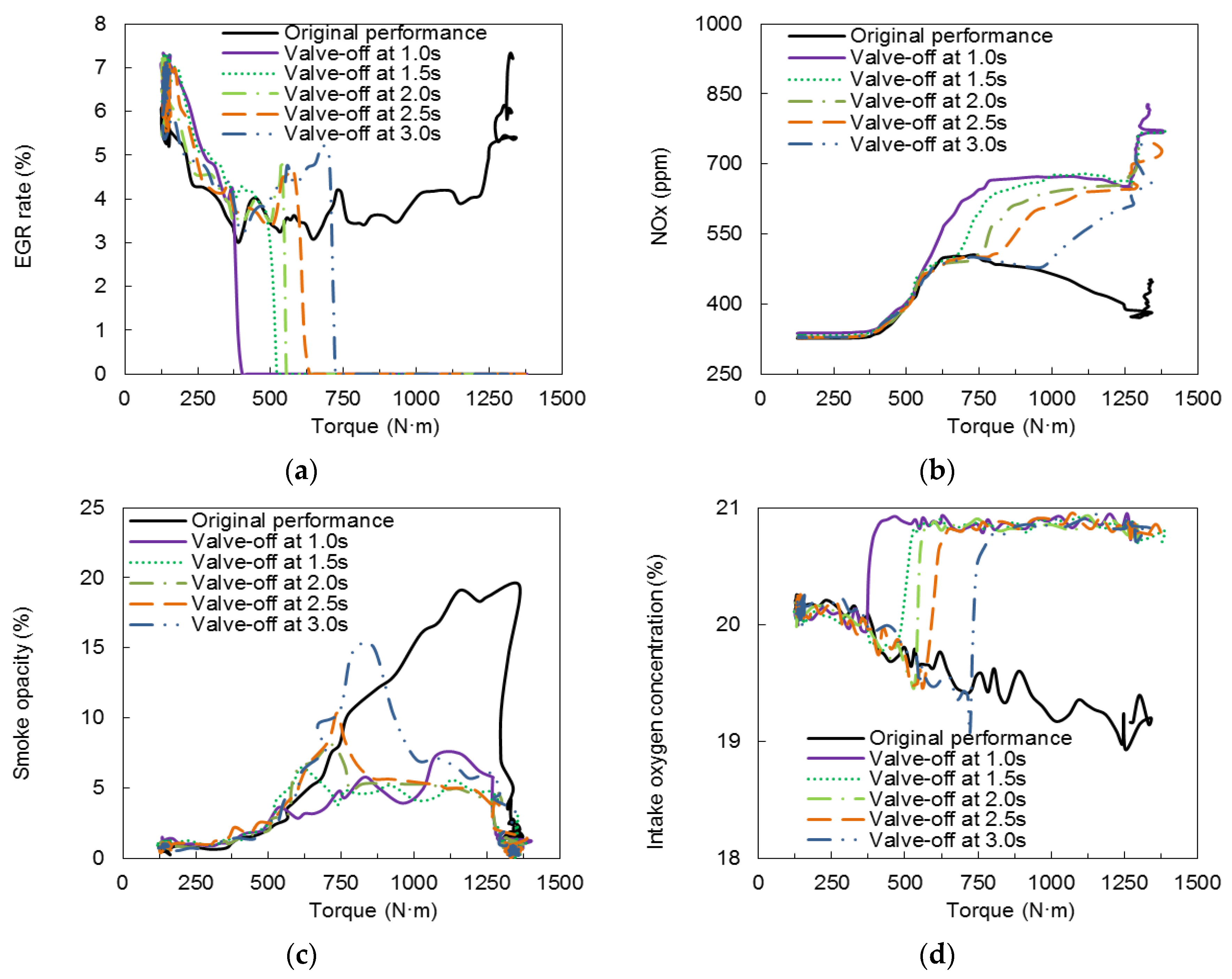
Figure 6.
Effect of different EGR valve-reopen time on diesel emission performance: (a) EGR rate; (b) NOx; (c) Smoke opacity.
Figure 6.
Effect of different EGR valve-reopen time on diesel emission performance: (a) EGR rate; (b) NOx; (c) Smoke opacity.
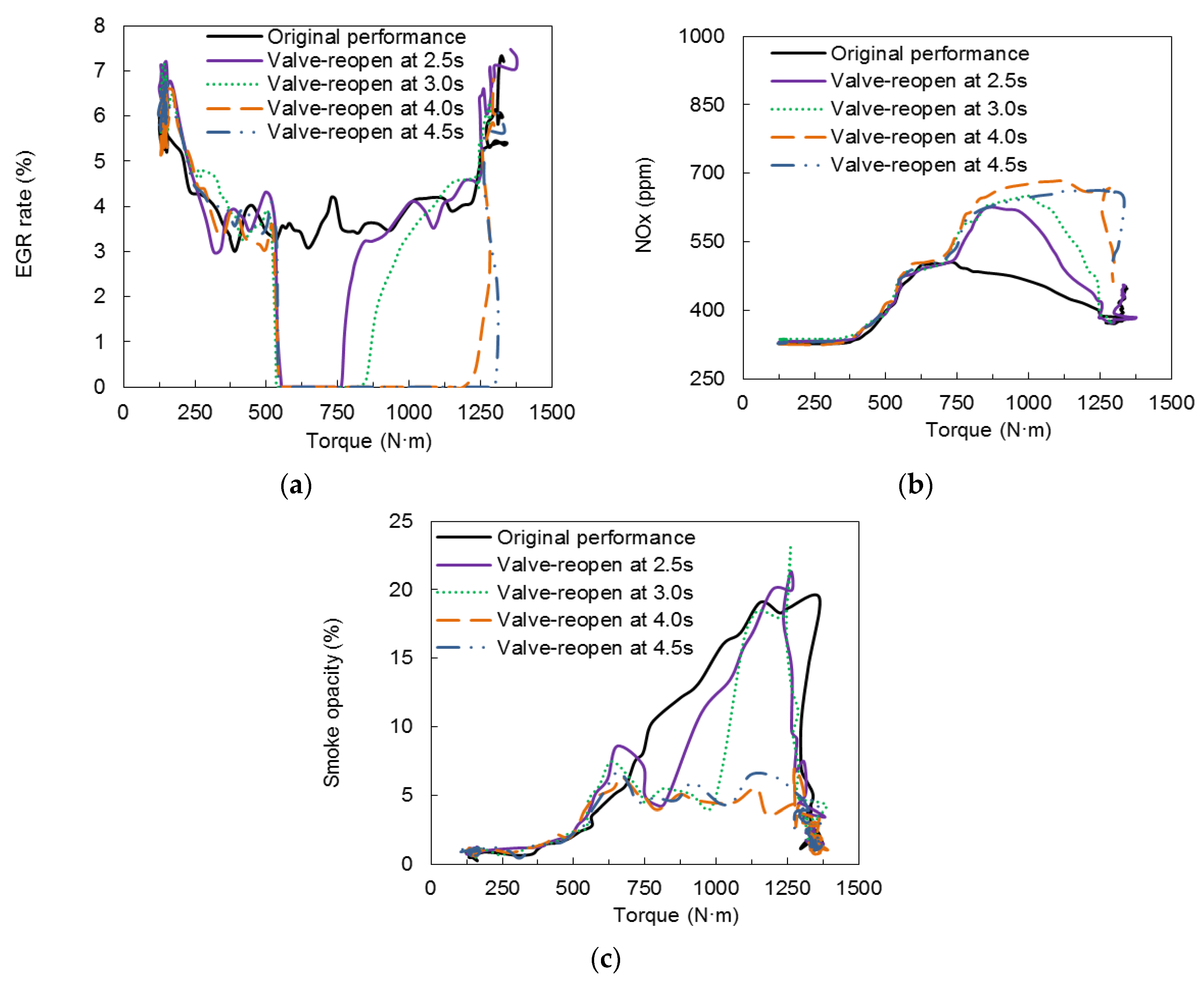
Figure 7.
Effect of different EGR valve reopened time on cumulative smoke proportion.
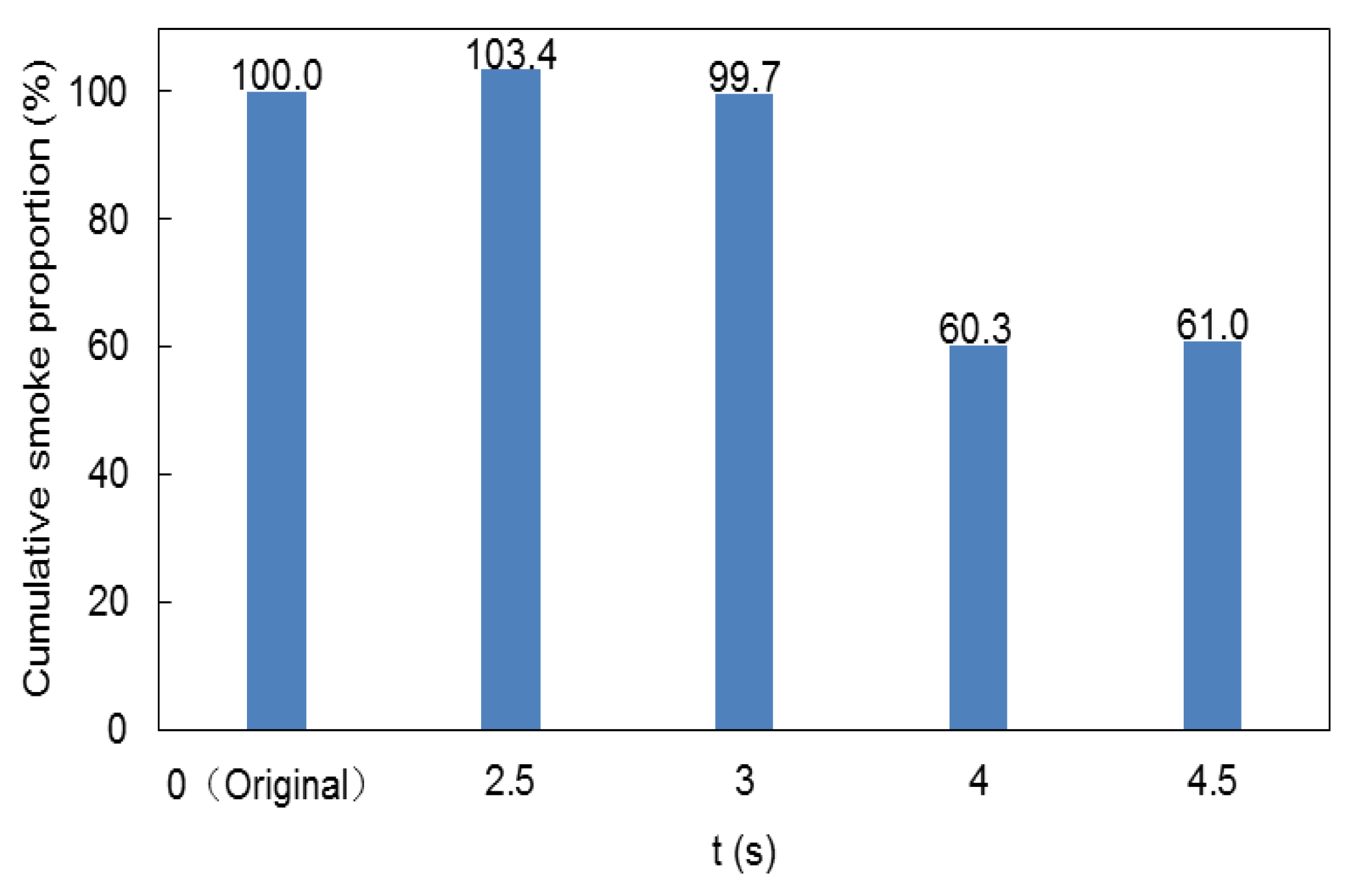
Figure 8.
Effect of close loop control strategy on transient performance: (a) EGR opening and EGR rate; (b) exhaust oxygen concentration; (c) NOx; (d) smoke opacity; (e) Air inflow concentration.
Figure 8.
Effect of close loop control strategy on transient performance: (a) EGR opening and EGR rate; (b) exhaust oxygen concentration; (c) NOx; (d) smoke opacity; (e) Air inflow concentration.

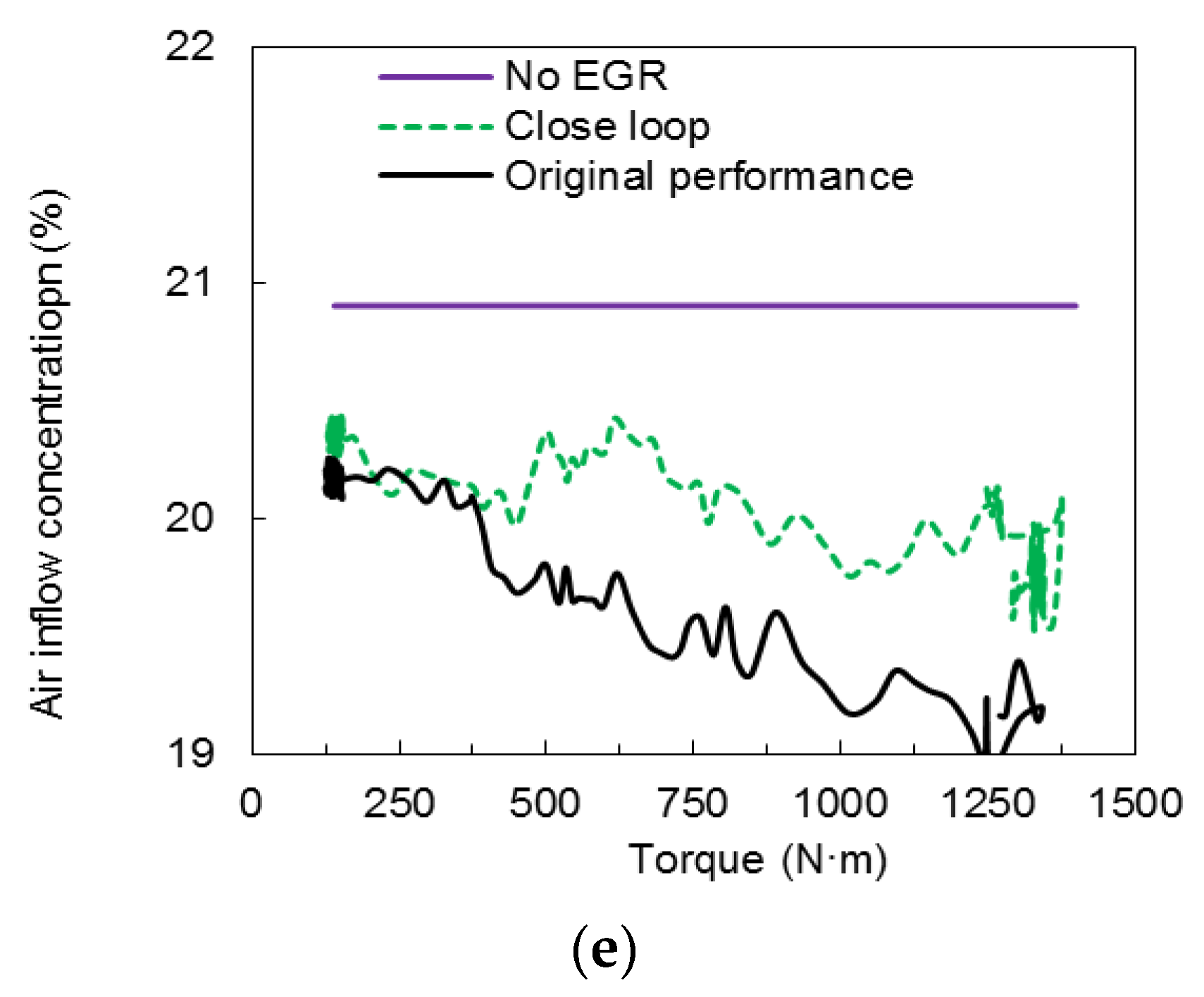
Figure 9.
Deviation degree of exhaust oxygen concentration.
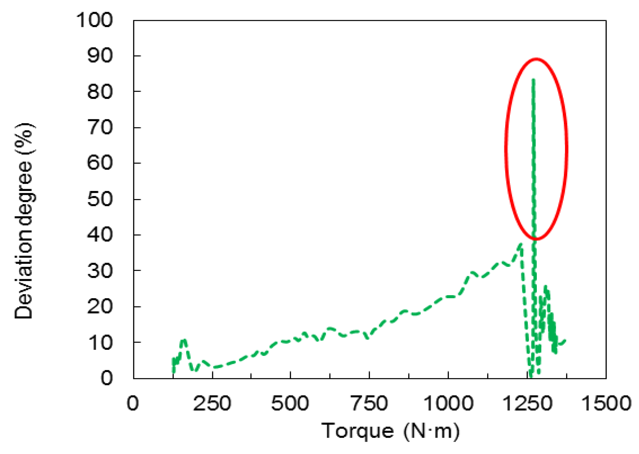
Figure 10.
Test plan of sectional-stage rail pressure (SSRP) strategy.
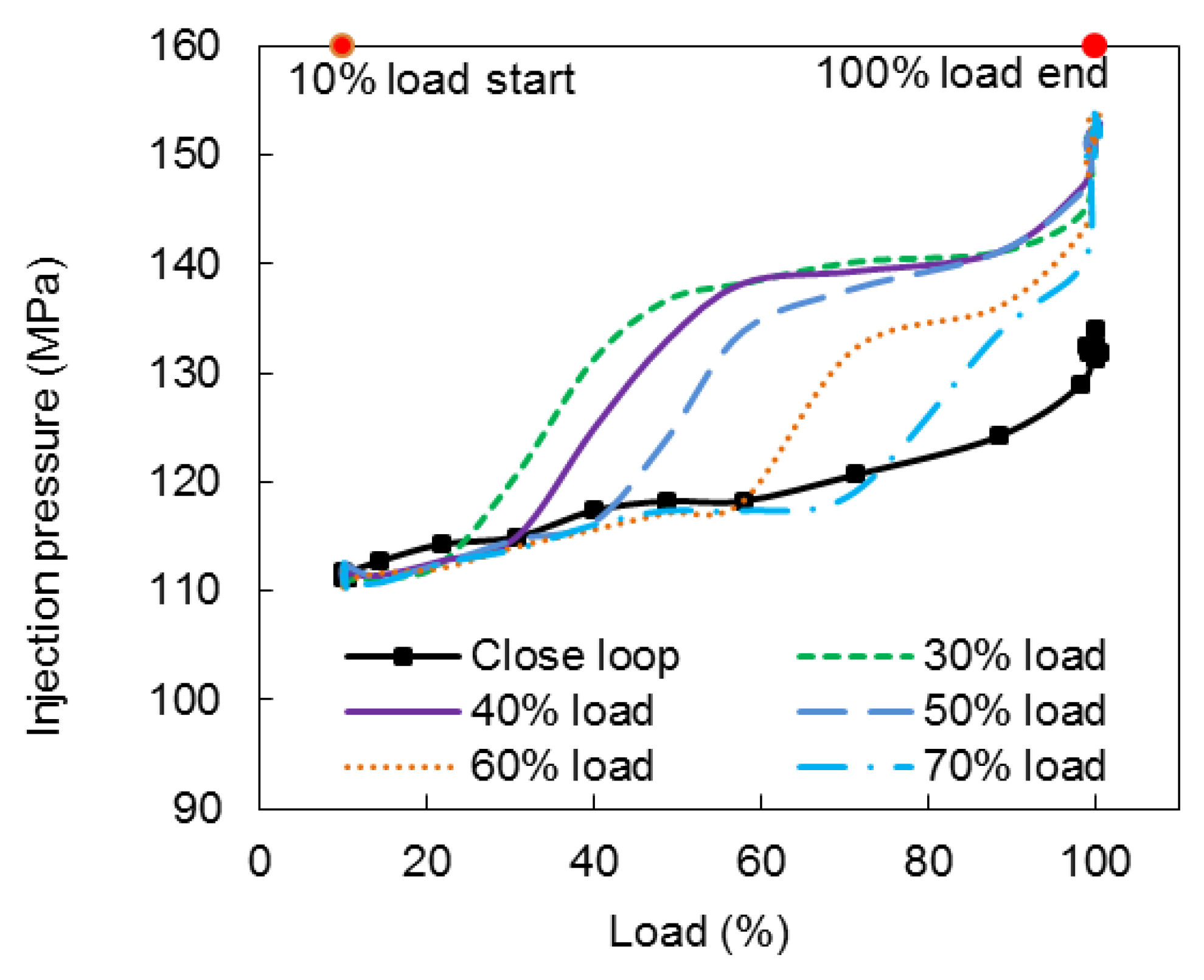
Figure 11.
Effect of SSRP strategy on combustion performance: (a) CA10; (b) CA50; (c) Pmax.
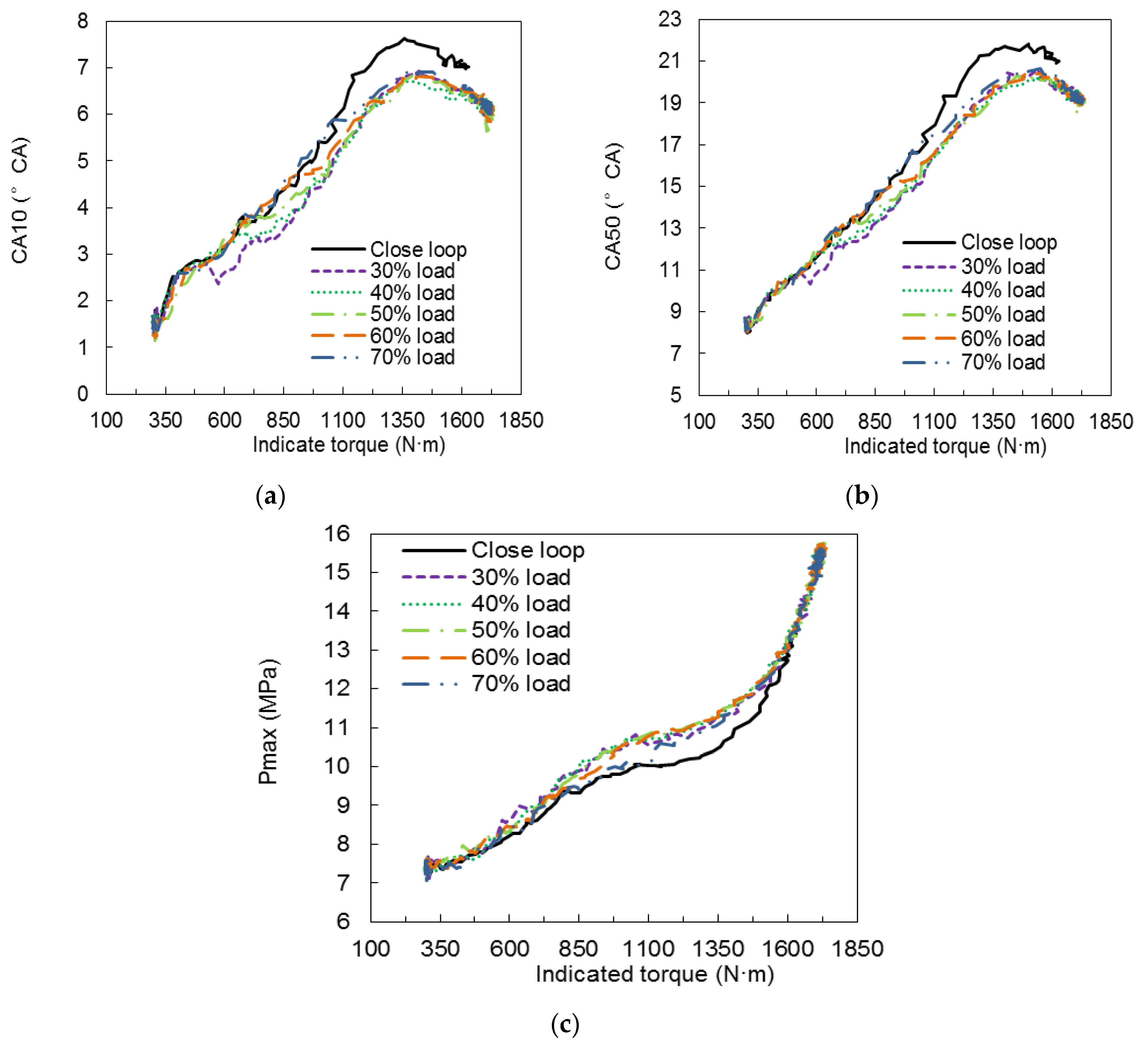
Figure 12.
Effect of SSRP strategy on transient performance: (a) NOx; (b) smoke opacity.
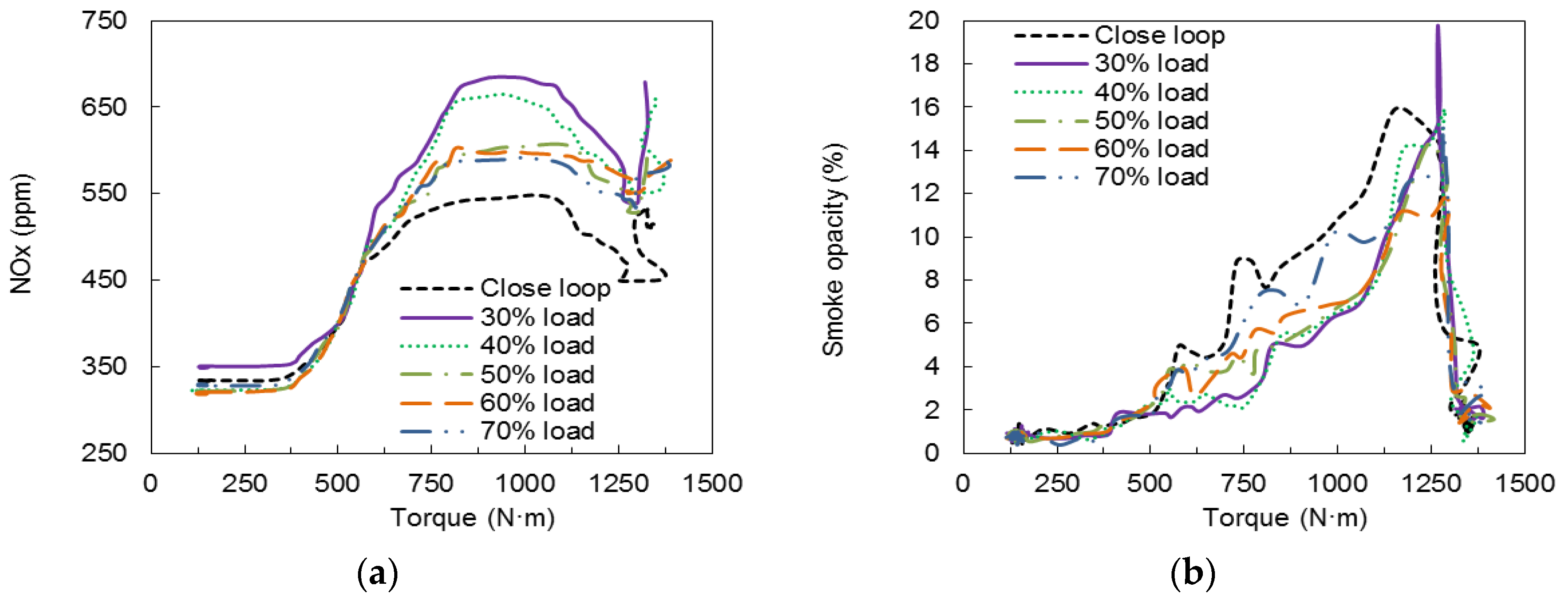
Figure 13.
Effect of SSRP strategy on cumulative smoke proportion.

Figure 14.
Effect of full-stage injection timing (FSIT) strategy on transient performance: (a) NOx; (b) smoke opacity.
Figure 14.
Effect of full-stage injection timing (FSIT) strategy on transient performance: (a) NOx; (b) smoke opacity.
Figure 15.
Effect of FSIT strategies on combustion performance: (a) CA10; (b) CA50.

Table 1.
Specifications of the basic engine.
| Item | Value |
|---|---|
| Engine Type | inline six-cylinder four-valve two-stage turbocharged with inter-cooling |
| Bore (mm) × Stroke (mm) | 112 × 145 |
| Rated power/(kW) | 257 at 2100 r/min |
| Displacement/(L) | 8.6 |
| Compression ratio | 17.0:1 |
| Turbocharged | HOLSET400 |
| Injection system | The 2nd generation of common-rail (Bosch) |
| Combustion chamber shape | ω-type |
Table 2.
The main instruments and accuracy.
| Equipment | Type | Accuracy |
|---|---|---|
| Eddy current dynamometer | CW440 | Speed: ±1 r/min |
| Torque: ±0.2~0.3%FS | ||
| EGR value | KNE-071-11 | 10 mm/60 step |
| In-cylinder pressure sensor | Kistler 6125 C | ±0.4%FS |
| Combustion analyzer | DEWE-2010 | Resolution: 0.2° CA |
| Air flow meter | AVL1000 | ±1.0%FS |
| Opacimeter | AVL439 | ±0.1%FS |
| NOx sensor | 5WK9-6614H | ±0.2%FS |
| Fuel mass flow meter | ToCeiL-CMFD/G | ±0.4%FS |
| Exhaust-gas analyzer | MEXA-7200DEGR | ±1.0%FS |
| dSPACE | MicroAutoBoxII 1401 | ADC: 12-bit |
| DAC: 12-bit |
Table 3.
Comparison of experimental results by different authors.
| Authors | Fangyuan Zhang, et al. | Daniel Alberer, et al. | David Heuwetter, et al. | |
|---|---|---|---|---|
| Qauntity | ||||
| NOx | 28.2% | 67.6% | 54.8% | |
| Smoke | 80.4% | 66.8% | 13.2% | |
© 2020 by the authors. Licensee MDPI, Basel, Switzerland. This article is an open access article distributed under the terms and conditions of the Creative Commons Attribution (CC BY) license (http://creativecommons.org/licenses/by/4.0/).
Share and Cite
MDPI and ACS Style
Zhang, F.; Wang, Z.; Tian, J.; Li, L.; Yu, K.; He, K. Effect of EGR and Fuel Injection Strategies on the Heavy-Duty Diesel Engine Emission Performance under Transient Operation. Energies 2020, 13, 566. https://doi.org/10.3390/en13030566
AMA Style
Zhang F, Wang Z, Tian J, Li L, Yu K, He K. Effect of EGR and Fuel Injection Strategies on the Heavy-Duty Diesel Engine Emission Performance under Transient Operation. Energies. 2020; 13(3):566. https://doi.org/10.3390/en13030566
Chicago/Turabian StyleZhang, Fangyuan, Zhongshu Wang, Jing Tian, Linlin Li, Kaibo Yu, and Kunyi He. 2020. "Effect of EGR and Fuel Injection Strategies on the Heavy-Duty Diesel Engine Emission Performance under Transient Operation" Energies 13, no. 3: 566. https://doi.org/10.3390/en13030566
Note that from the first issue of 2016, this journal uses article numbers instead of page numbers. See further details here.