Effective Permeability of Multi Air Gap Ferrite Core 3-Phase Medium Frequency Transformer in Isolated DC-DC Converters

 , , , and
Abstract
:
1. Introduction
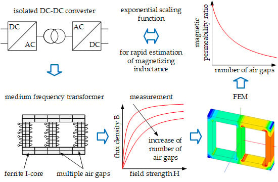
- Determination of the equivalent B(H) and the equivalent magnetic permeability in a three-phase multi air gap ferrite core MFT.
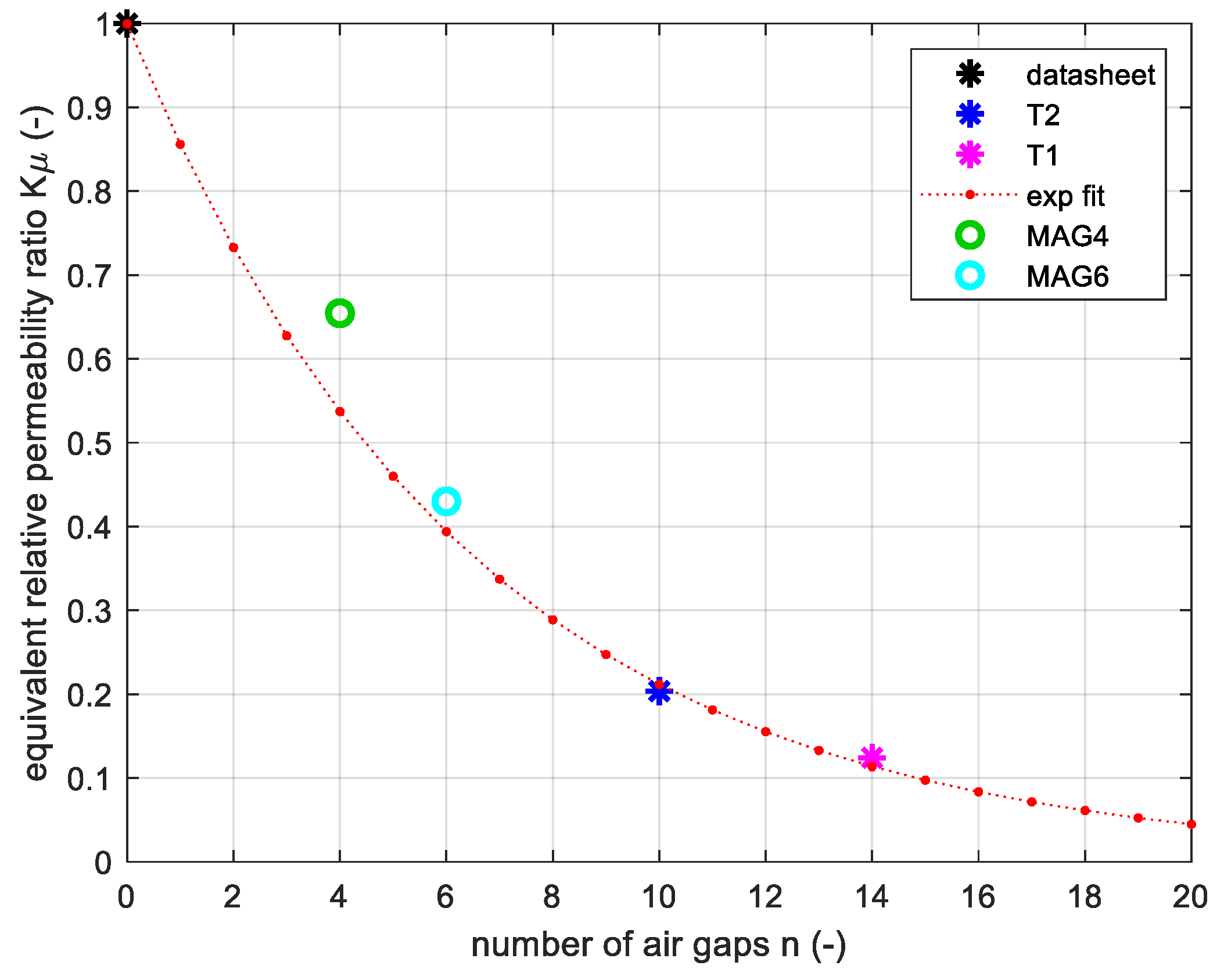
- Demonstration that the equivalent magnetic permeability and the average air gap length of the multi air gap ferrite core MFT are nonlinear functions of the number of air gaps.
- Proposal of an exponential scaling function, enabling a rapid estimation of the magnetizing inductance based on the ferrite material datasheet only.
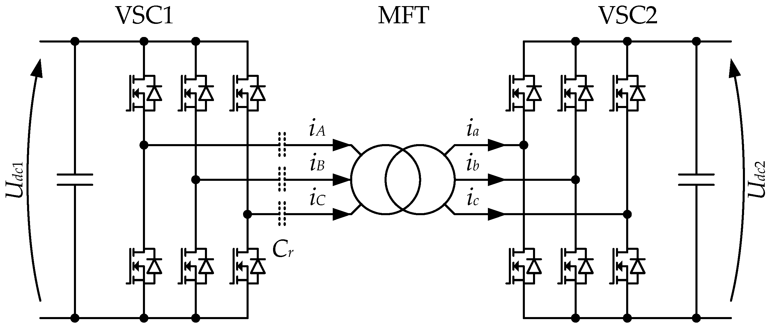
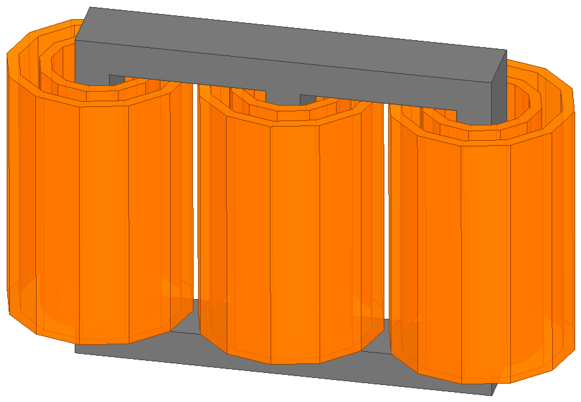
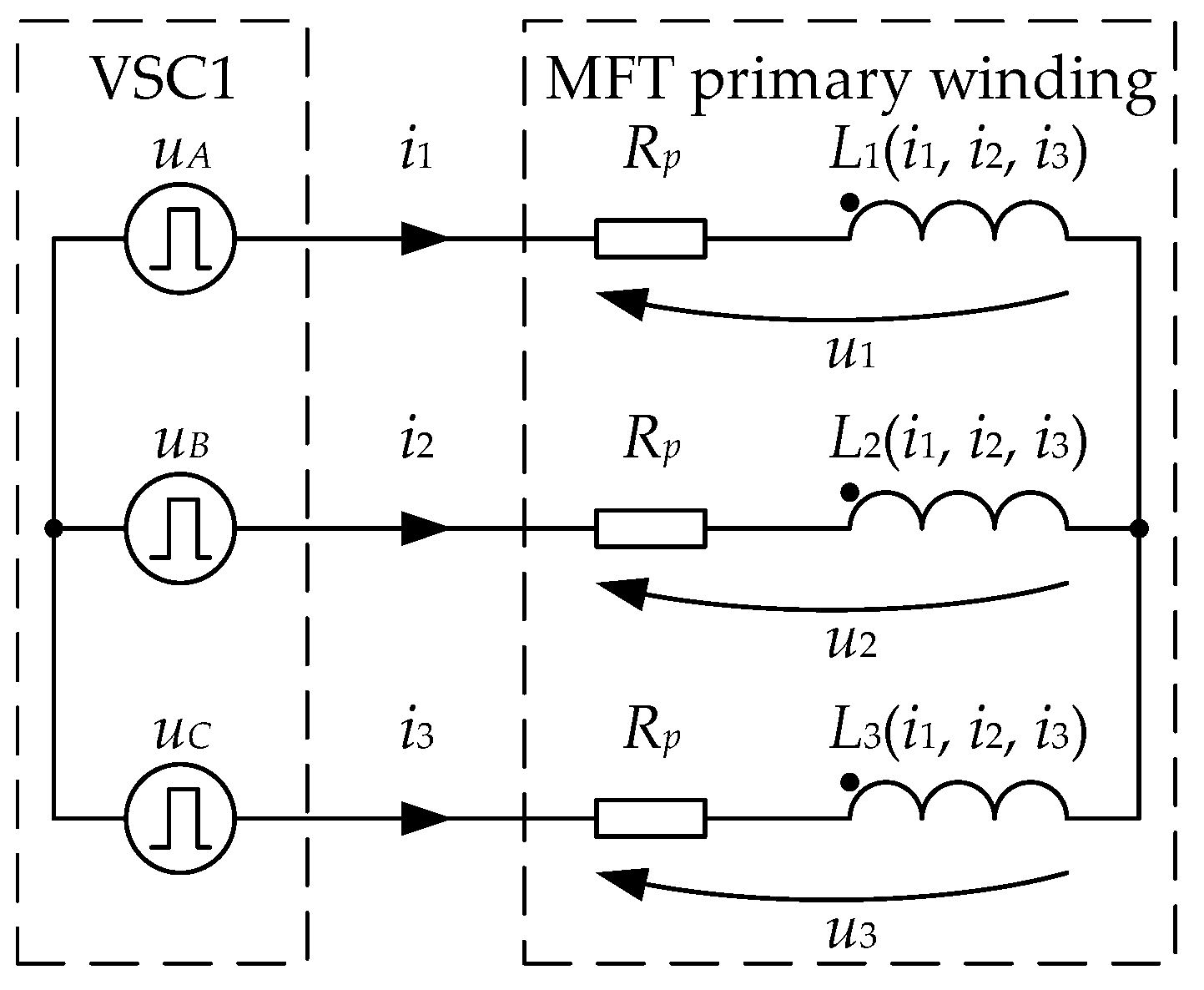
2. High Power Medium Frequency Transformer
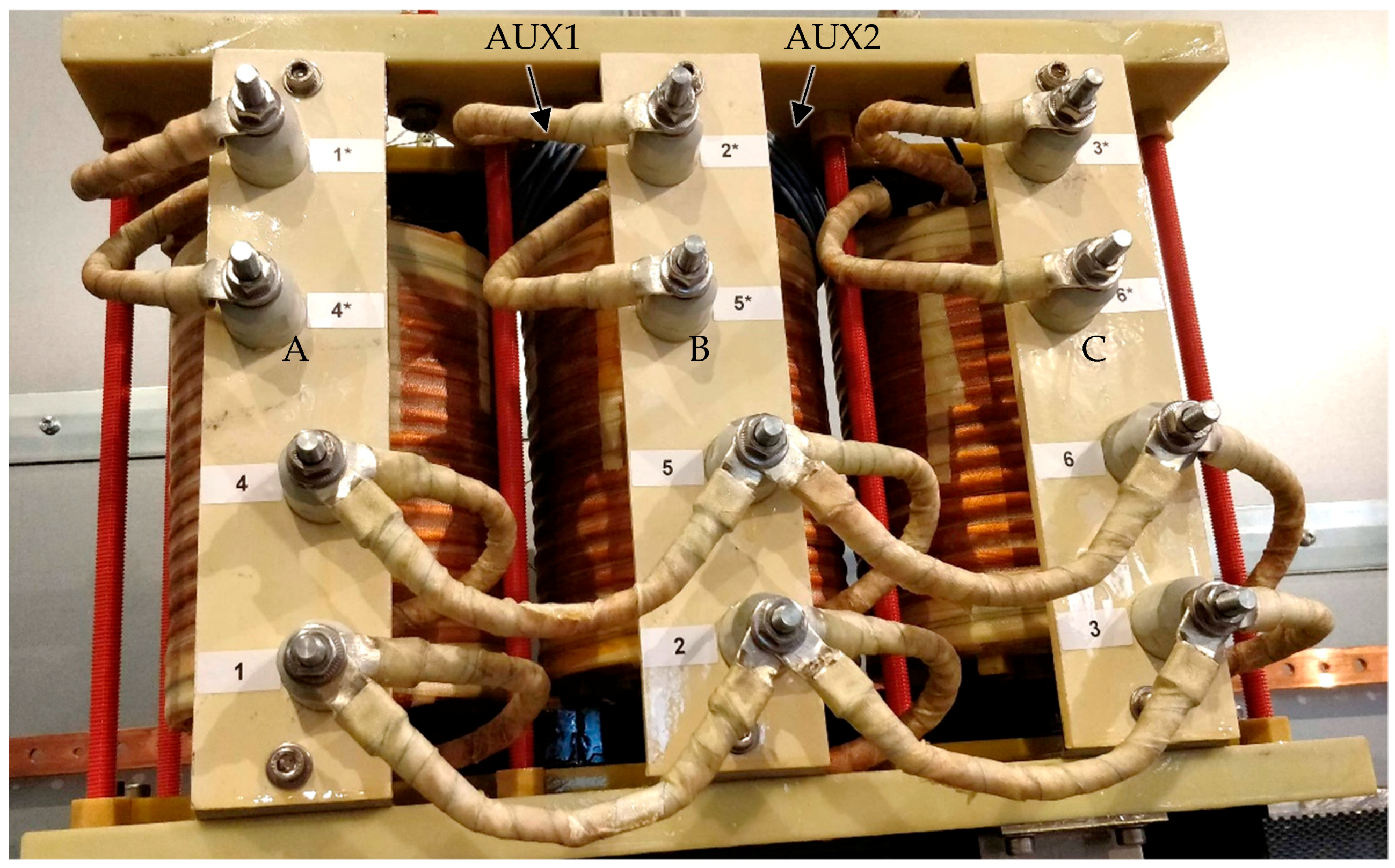
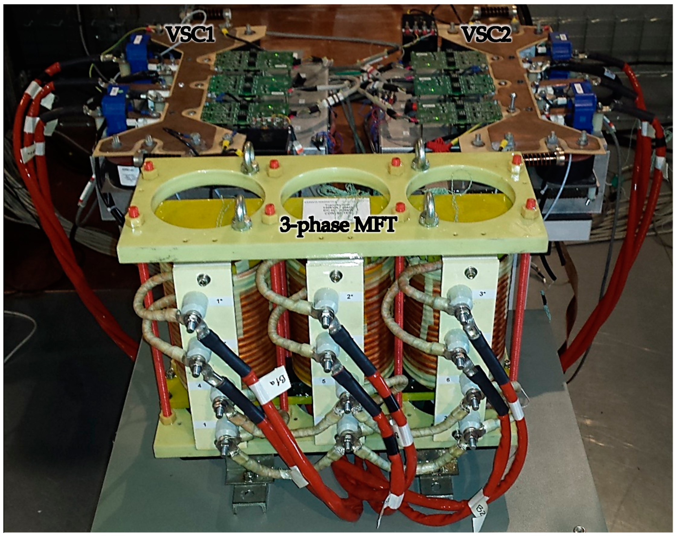
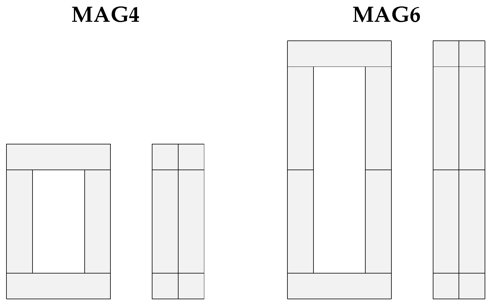
2.1. MFT Prototypes
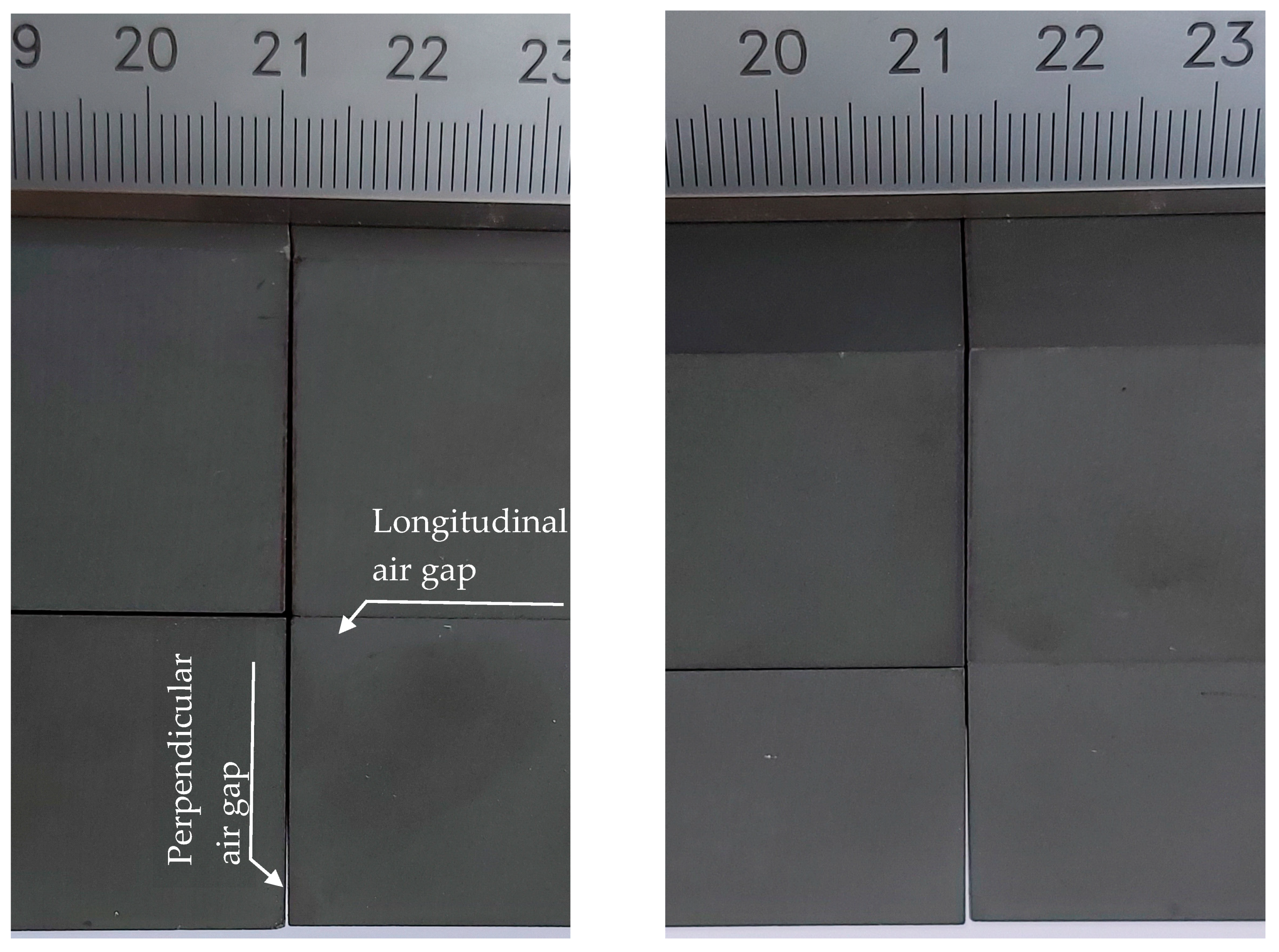
2.2. Magnetic Core
3. Equivalent B(H) Measurement
3.1. Measurement Setup
3.2. Measurement Results
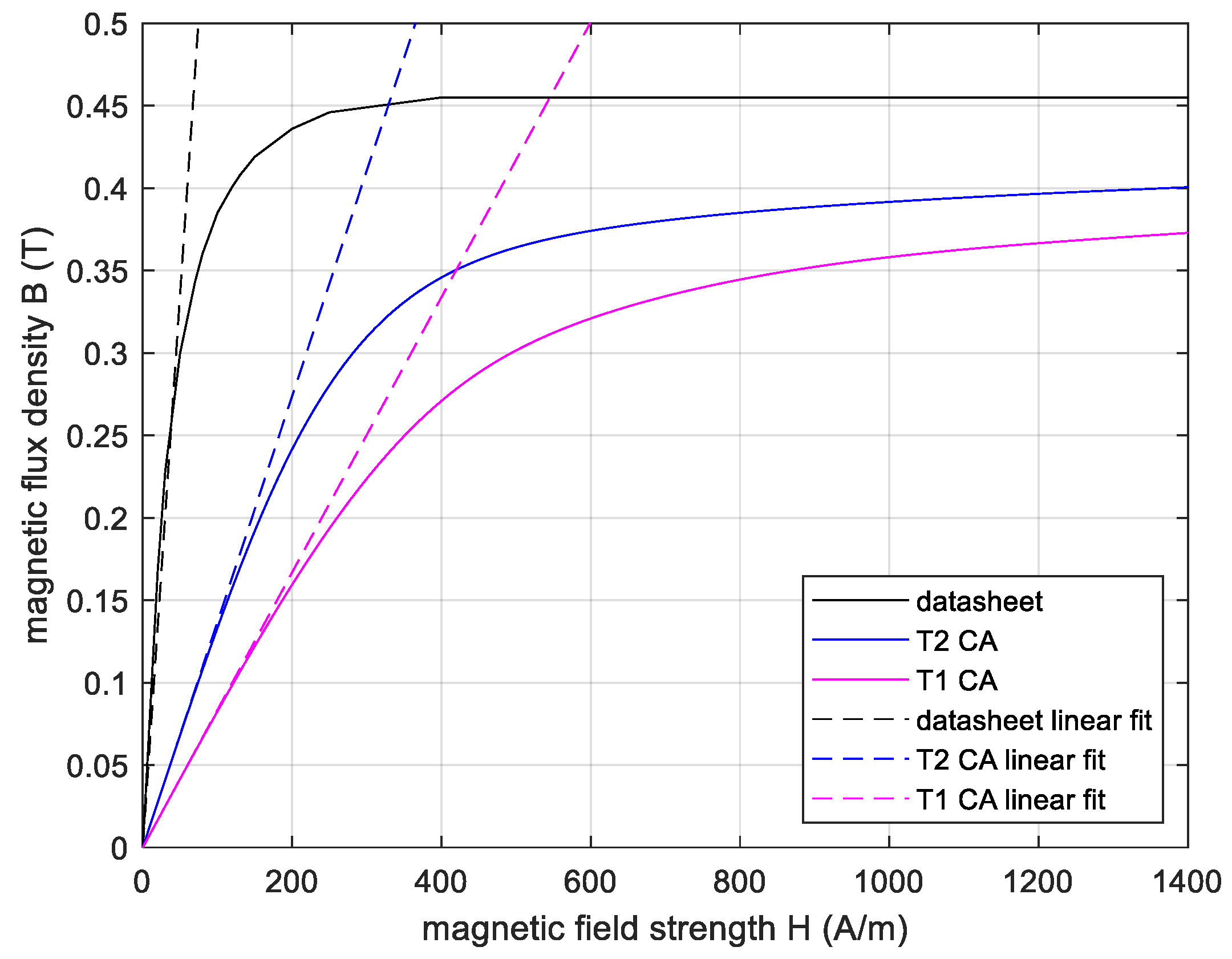
3.3. Synthesis of Equivalent B(H) Measurement
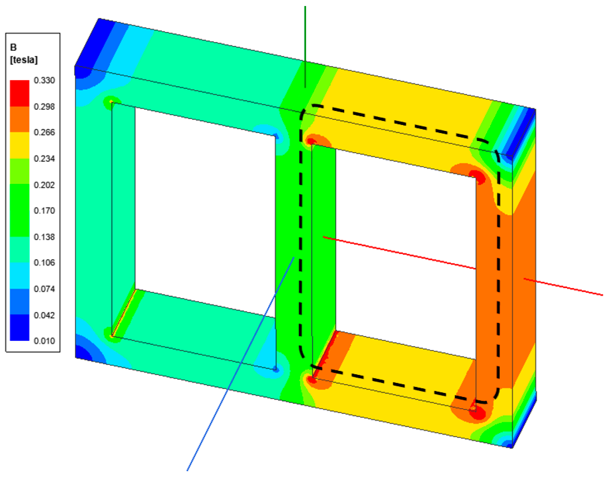
4. Finite Element Simulation
4.1. Finite Element Model
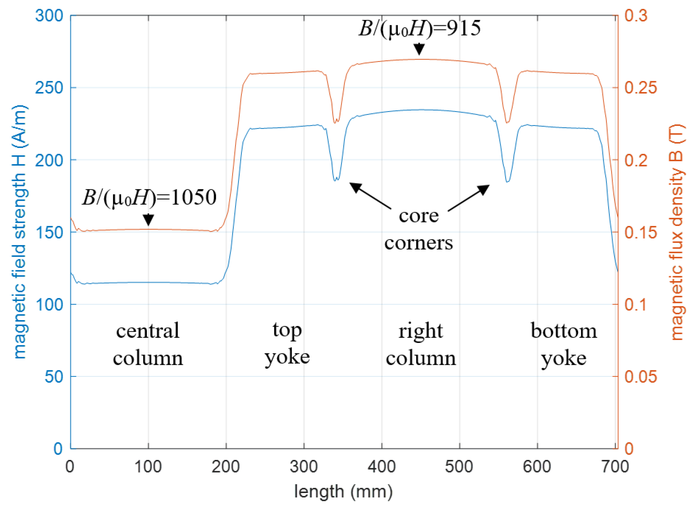
4.2. Magnetic Simulations
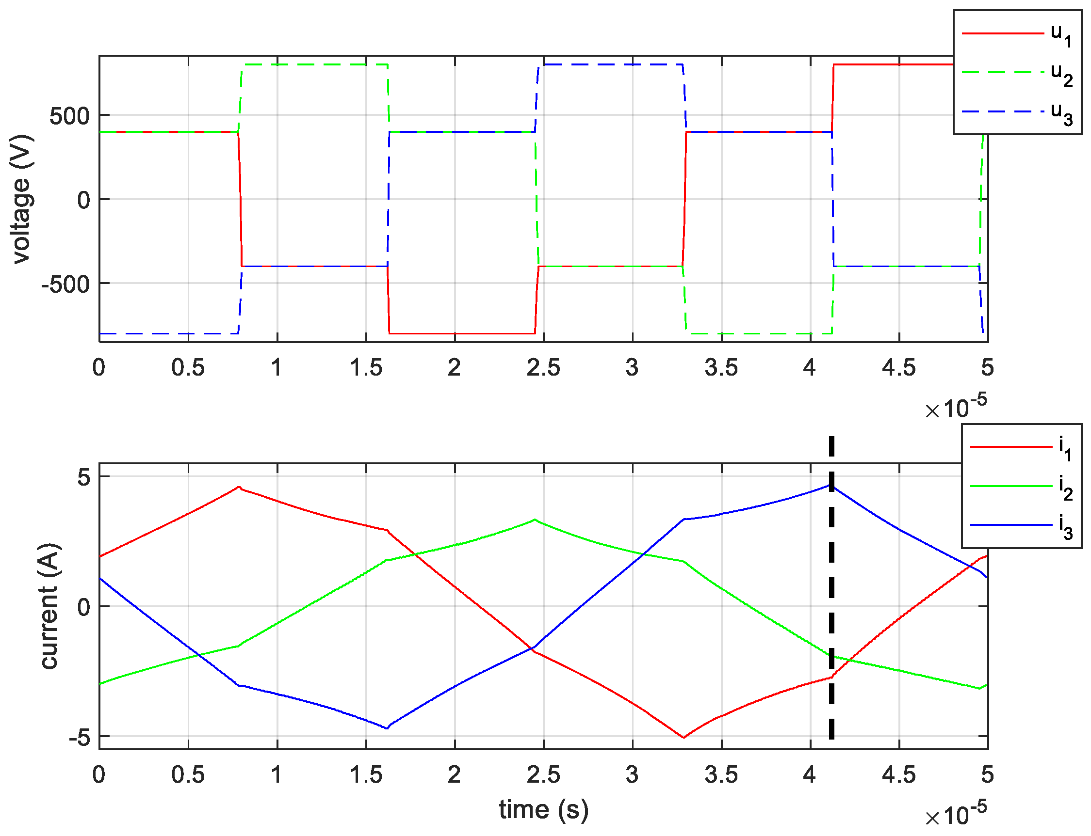
5. Experimental Verifications
5.1. Converter Test Bench
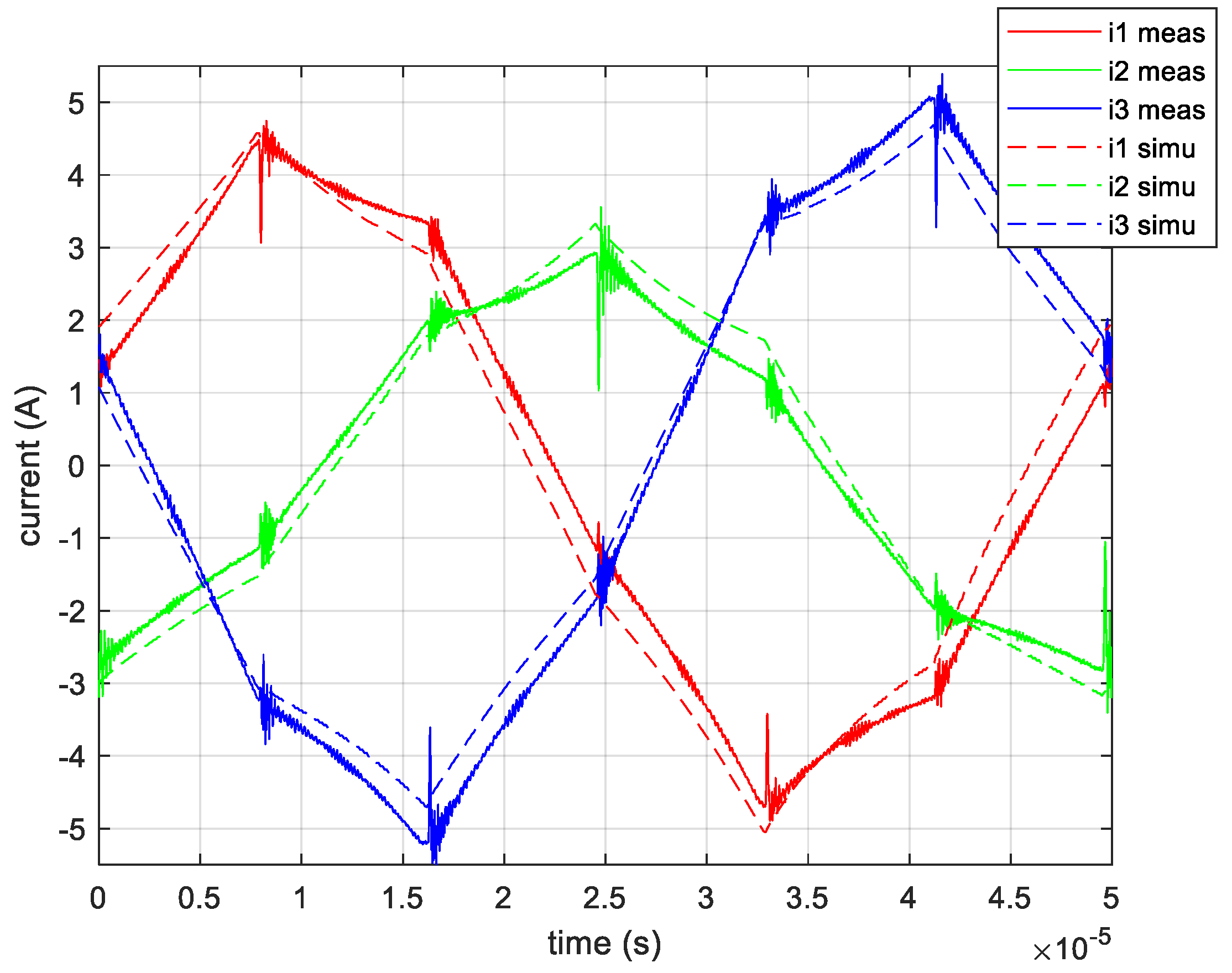
5.2. No Load Test Experimental Results
6. Scaling of Relative Permeability
7. Conclusions
Author Contributions
Funding
Acknowledgments
Conflicts of Interest
Appendix A

Appendix B

References
- Yang, B.; Lee, F.C.; Zhang, A.J. Guisong Huang LLC resonant converter for front end DC/DC conversion. In Proceedings of the APEC. Seventeenth Annual IEEE Applied Power Electronics Conference and Exposition (Cat. No.02CH37335), Dallas, TX, USA, 10–14 March 2002; Volume 2, pp. 1108–1112. [Google Scholar]
- De Doncker, R.W.A.A.; Divan, D.M.; Kheraluwala, M.H. A three-phase soft-switched high-power-density DC/DC converter for high-power applications. IEEE Trans. Ind. Appl. 1991, 27, 63–73. [Google Scholar] [CrossRef]
- Schwarz, F.C.; Klaassens, J.B. A Controllable 45-kW Current Source for DC Machines. IEEE Trans. Ind. Appl. 1979, IA-15, 437–444. [Google Scholar] [CrossRef]
- Mweene, L.H.; Wright, C.A.; Schlecht, M.F. A 1 kW 500 kHz front-end converter for a distributed power supply system. IEEE Trans. Power Electron. 1991, 6, 398–407. [Google Scholar] [CrossRef]
- Adamowicz, M. Power Electronics Building Blocks for implementing Smart MV/LV Distribution Transformers for Smart Grid. Acta Energetica 2014, 4, 6–13. [Google Scholar] [CrossRef]
- Walker, G.R.; Sernia, P.C. Cascaded DC-DC converter connection of photovoltaic modules. IEEE Trans. Power Electron. 2004, 19, 1130–1139. [Google Scholar] [CrossRef]
- Dincan, C.G.; Kjaer, P.; Chen, Y.-H.; Sarrá-Macia, E.; Munk-Nielsen, S.; Bak, C.L.; Vaisambhayana, S. Design of a High-Power Resonant Converter for DC Wind Turbines. IEEE Trans. Power Electron. 2019, 34, 6136–6154. [Google Scholar] [CrossRef]
- Du, Y.; Lukic, S.; Jacobson, B.; Huang, A. Review of high power isolated bi-directional DC-DC converters for PHEV/EV DC charging infrastructure. In Proceedings of the 2011 IEEE Energy Conversion Congress and Exposition, Phoenix, AZ, USA, 17–22 September 2011; pp. 553–560. [Google Scholar]
- Ruffo, R.; Khalilian, M.; Cirimele, V.; Guglielmi, P.; Cesano, M. Theoretical and experimental comparison of two interoperable dynamic wireless power transfer systems for electric vehicles. In Proceedings of the 2017 IEEE Southern Power Electronics Conference (SPEC), Puerto Varas, Chile, 4–7 December 2017; pp. 1–6. [Google Scholar]
- Garcia-Bediaga, A.; Villar, I.; Rujas, A.; Etxeberria-Otadui, I.; Rufer, A. Analytical Models of Multiphase Isolated Medium-Frequency DC–DC Converters. IEEE Trans. Power Electron. 2017, 32, 2508–2520. [Google Scholar] [CrossRef]
- Lagier, T. Convertisseurs Continu-Continu Pour Les Réseaux d’électricité à Courant Continu. Doctoral Thesis, INPT, Toulouse, France, 2016. [Google Scholar]
- Xue, J.; Wang, F.; Boroyevich, D.; Shen, Z. Single-phase vs. three-phase high density power transformers. In Proceedings of the 2010 IEEE Energy Conversion Congress and Exposition, Atlanta, GA, USA, 12–16 September 2010; pp. 4368–4375. [Google Scholar]
- Lee, Y.; Vakil, G.; Watson, A.J.; Wheeler, P.W. Geometry optimization and characterization of three-phase medium frequency transformer for 10 kVA Isolated DC-DC converter. In Proceedings of the 2017 IEEE Energy Conversion Congress and Exposition (ECCE), Cincinnati, OH, USA, 1–5 October 2017; pp. 511–518. [Google Scholar]
- Noah, M.; Kimura, S.; Endo, S.; Yamamoto, M.; Imaoka, J.; Umetani, K.; Martinez, W. A novel three-phase LLC resonant converter with integrated magnetics for lower turn-off losses and higher power density. In Proceedings of the 2017 IEEE Applied Power Electronics Conference and Exposition (APEC), Tampa, FL, USA, 26–30 March 2017; pp. 322–329. [Google Scholar]
- Soltau, N.; Stagge, H.; De Doncker, R.W.; Apeldoorn, O. Development and demonstration of a medium-voltage high-power DC-DC converter for DC distribution systems. In Proceedings of the 2014 IEEE 5th International Symposium on Power Electronics for Distributed Generation Systems (PEDG), Galway, Ireland, 24–27 June 2014; pp. 1–8. [Google Scholar]
- Kim, E.-S.; Oh, J.-S. High-Efficiency Bidirectional LLC Resonant Converter with Primary Auxiliary Windings. Energies 2019, 12, 4692. [Google Scholar] [CrossRef] [Green Version]
- Bouvier, Y.E.; Serrano, D.; Borović, U.; Moreno, G.; Vasić, M.; Oliver, J.A.; Alou, P.; Cobos, J.A.; Carmena, J. ZVS Auxiliary Circuit for a 10 kW Unregulated LLC Full-Bridge Operating at Resonant Frequency for Aircraft Application. Energies 2019, 12, 1850. [Google Scholar] [CrossRef] [Green Version]
- Morel, F.; Stackler, C.; Ladoux, P.; Fouineau, A.; Wallart, F.; Evans, N.; Dworakowski, P. Power electronic traction transformers in 25 kV/50 Hz systems: Optimisation of DC/DC Isolated Converters with 3.3 kV SiC MOSFETs. In Proceedings of the PCIM Europe 2019; International Exhibition and Conference for Power Electronics, Intelligent Motion, Renewable Energy and Energy Management, Nuremberg, Germany, 7–9 May 2019; pp. 1–8. [Google Scholar]
- Dujic, D.; Steinke, G.K.; Bellini, M.; Rahimo, M.; Storasta, L.; Steinke, J.K. Characterization of 6.5 kV IGBTs for High-Power Medium-Frequency Soft-Switched Applications. IEEE Trans. Power Electron. 2014, 29, 906–919. [Google Scholar] [CrossRef]
- Huber, J.E.; Rothmund, D.; Wang, L.; Kolar, J.W. Full-ZVS modulation for all-SiC ISOP-type isolated front end (IFE) solid-state transformer. In Proceedings of the 2016 IEEE Energy Conversion Congress and Exposition (ECCE), Milwaukee, WI, USA, 18–22 September 2016; pp. 1–8. [Google Scholar]
- Mogorovic, M.; Dujic, D. Medium Frequency Transformer Design and Optimization. In Proceedings of the PCIM Europe 2017; International Exhibition and Conference for Power Electronics, Intelligent Motion, Renewable Energy and Energy Management, Nuremberg, Germany, 16–18 May 2017; pp. 1–8. [Google Scholar]
- Everts, J. Design and Optimization of an Efficient (96.1%) and Compact (2 kW/dm3) Bidirectional Isolated Single-Phase Dual Active Bridge AC-DC Converter. Energies 2016, 9, 799. [Google Scholar] [CrossRef] [Green Version]
- Mogorovic, M.; Dujic, D. 100 kW, 10 kHz Medium-Frequency Transformer Design Optimization and Experimental Verification. IEEE Trans. Power Electron. 2019, 34, 1696–1708. [Google Scholar] [CrossRef] [Green Version]
- Villar, I.; Mir, L.; Etxeberria-Otadui, I.; Colmenero, J.; Agirre, X.; Nieva, T. Optimal design and experimental validation of a Medium-Frequency 400 kVA power transformer for railway traction applications. In Proceedings of the 2012 IEEE Energy Conversion Congress and Exposition (ECCE), Raleigh, NC, USA, 15–20 September 2012; pp. 684–690. [Google Scholar]
- Ortiz, G.; Biela, J.; Bortis, D.; Kolar, J.W. 1 Megawatt, 20 kHz, isolated, bidirectional 12 kV to 1.2 kV DC-DC converter for renewable energy applications. In Proceedings of the 2010 International Power Electronics Conference—ECCE ASIA, Sapporo, Japan, 21–24 June 2010; pp. 3212–3219. [Google Scholar]
- Villar, I.; Garcia-Bediaga, A.; Viscarret, U.; Etxeberria-Otadui, I.; Rufer, A. Proposal and validation of medium-frequency power transformer design methodology. In Proceedings of the 2011 IEEE Energy Conversion Congress and Exposition, Phoenix, AZ, USA, 17–22 September 2011; pp. 3792–3799. [Google Scholar]
- Hurley, W.G.; Merkin, T.; Duffy, M. The Performance Factor for Magnetic Materials Revisited: The Effect of Core Losses on the Selection of Core Size in Transformers. IEEE Power Electron. Mag. 2018, 5, 26–34. [Google Scholar] [CrossRef]
- Ruiz-Robles, D.; Ortíz-Marín, J.; Venegas-Rebollar, V.; Moreno-Goytia, E.; Granados-Lieberman, D.; Rodríguez-Rodriguez, J. Nanocrystalline and Silicon Steel Medium-Frequency Transformers Applied to DC-DC Converters: Analysis and Experimental Comparison. Energies 2019, 12, 2062. [Google Scholar] [CrossRef] [Green Version]
- Ruiz-Robles, D.; Venegas-Rebollar, V.; Anaya-Ruiz, A.; Moreno-Goytia, E.L.; Rodríguez-Rodríguez, J.R. Design and Prototyping Medium-Frequency Transformers Featuring a Nanocrystalline Core for DC–DC Converters. Energies 2018, 11, 2081. [Google Scholar] [CrossRef] [Green Version]
- Bahmani, M.A. Design considerations of medium-frequency power transformers in HVDC applications. In Proceedings of the 2017 Twelfth International Conference on Ecological Vehicles and Renewable Energies (EVER), Monte Carlo, Monaco, 11–13 April 2017; pp. 1–6. [Google Scholar]
- Stojadinović, M.; Biela, J. Modelling and Design of a Medium Frequency Transformer for High Power DC-DC Converters. In Proceedings of the 2018 International Power Electronics Conference (IPEC-Niigata 2018 -ECCE Asia), Niigata, Japan, 20–24 May 2018; pp. 1103–1110. [Google Scholar]
- Stackler, C.; Morel, F.; Ladoux, P.; Fouineau, A.; Wallart, F.; Evans, N. Optimal sizing of a power electronic traction transformer for railway applications. In Proceedings of the IECON 2018—44th Annual Conference of the IEEE Industrial Electronics Society, Washington, DC, USA, 21–23 October 2018; pp. 1380–1387. [Google Scholar]
- Keuck, L.; Schafmeister, F.; Boecker, J.; Jungwirth, H.; Schmidhuber, M. Computer-Aided Design and Optimization of an Integrated Transformer with Distributed Air Gap and Leakage Path for LLC Resonant Converter. In Proceedings of the PCIM Europe 2019; International Exhibition and Conference for Power Electronics, Intelligent Motion, Renewable Energy and Energy Management, Nuremberg, Germany, 7–9 May 2019; pp. 1–8. [Google Scholar]
- Noah, M.; Endo, S.; Kimura, S.; Yamamoto, M.; Imaoka, J.; Umetani, K.; Hiraki, E. An investigation into a slight-variation of the transformer effective permeability in LLC resonant converter. In Proceedings of the 2017 19th European Conference on Power Electronics and Applications (EPE’17 ECCE Europe), Warsaw, Poland, 11–14 September 2017. [Google Scholar]
- Ayachit, A.; Kazimierczuk, M.K. Sensitivity of effective relative permeability for gapped magnetic cores with fringing effect. IET Circuits Devices Syst. 2017, 11, 209–215. [Google Scholar] [CrossRef]
- Salas, R.A.; Pleite, J. Simulation of the Saturation and Air-Gap Effects in a POT Ferrite Core With a 2-D Finite Element Model. IEEE Trans. Magn. 2011, 47, 4135–4138. [Google Scholar] [CrossRef]
- Balakrishnan, A.; Joines, W.T.; Wilson, T.G. Air-gap reluctance and inductance calculations for magnetic circuits using a Schwarz-Christoffel transformation. IEEE Trans. Power Electron. 1997, 12, 654–663. [Google Scholar] [CrossRef]
- Stenglein, E.; Albach, M. A Novel Approach to Calculate the Reluctance of Air-Gaps in Ferrite Cores. In Proceedings of the PCIM Europe 2017; International Exhibition and Conference for Power Electronics, Intelligent Motion, Renewable Energy and Energy Management, Nuremberg, Germany, 16–18 May 2017; pp. 1–8. [Google Scholar]
- Ayachit, A.; Kazimierczuk, M.K. Steinmetz Equation for Gapped Magnetic Cores. IEEE Magn. Lett. 2016, 7, 1–4. [Google Scholar] [CrossRef]
- Komma, T.; Gueldner, H. The effect of different air-gap positions on the winding losses of modern planar ferrite cores in switch mode power supplies. In Proceedings of the Automation and Motion 2008 International Symposium on Power Electronics, Electrical Drives, Ischia, Italy, 11–13 June 2008; pp. 632–637. [Google Scholar]
- Albach, M.; Rossmanith, H. The influence of air gap size and winding position on the proximity losses in high frequency transformers. In Proceedings of the 2001 IEEE 32nd Annual Power Electronics Specialists Conference (IEEE Cat. No.01CH37230), Vancouver, BC, Canada, 17–21 June 2001; Volume 3, pp. 1485–1490. [Google Scholar]
- Zurek, S. FEM Simulation of Effect of Non-Uniform Air Gap on Apparent Permeability of Cut Cores. IEEE Trans. Magn. 2012, 48, 1520–1523. [Google Scholar] [CrossRef]
- Stenglein, E.; Kuebrich, D.; Albach, M. Analytical calculation of the current depending inductance of a stepped air gap inductor. In Proceedings of the 2016 18th European Conference on Power Electronics and Applications (EPE’16 ECCE Europe), Karlsruhe, Germany, 5–9 September 2016; pp. 1–10. [Google Scholar]
- Lesniewska, E.; Jalmuzny, W. Influence of the number of core air gaps on transient state parameters of TPZ class protective current transformers. IET Sci. Meas. Technol. 2009, 3, 105–112. [Google Scholar] [CrossRef]
- Nakata, T.; Takahashi, N.; Kawase, Y. Magnetic performance of step-lap joints in distribution transformer cores. IEEE Trans. Magn. 1982, 18, 1055–1057. [Google Scholar] [CrossRef]
- Pietruszka, M.; Napieralska-Juszczak, E. Lamination of T-joints in the transformer core. IEEE Trans. Magn. 1996, 32, 1180–1183. [Google Scholar] [CrossRef]
- Hihat, N.; Napieralska-Juszczak, E.; Lecointe, J.-P.; Sykulski, J.K.; Komeza, K. Equivalent Permeability of Step-Lap Joints of Transformer Cores: Computational and Experimental Considerations. IEEE Trans. Magn. 2011, 47, 244–251. [Google Scholar] [CrossRef] [Green Version]
- Gyselinck, J.; Melkebeek, J. Two-dimensional finite element modelling of overlap joints in transformer cores. COMPEL Int. J. Comput. Math. Electr. Electron. Eng. 2001, 20, 253–268. [Google Scholar] [CrossRef]
- Shin, P.S.; Lee, J. Magnetic field analysis of amorphous core transformer using homogenization technique. IEEE Trans. Magn. 1997, 33, 1808–1811. [Google Scholar] [CrossRef]
- Hollaus, K.; Schöbinger, M. Multiscale finite element method for perturbation of laminated structures. In Proceedings of the 2017 International Conference on Electromagnetics in Advanced Applications (ICEAA), Verona, Italy, 11–15 September 2017; pp. 1262–1263. [Google Scholar]
- Hauck, A.; Ertl, M.; Schöberl, J.; Kaltenbacher, M. Accurate magnetostatic simulation of step-lap joints in transformer cores using anisotropic higher order FEM. COMPEL Int. J. Comput. Math. Electr. Electron. Eng. 2013, 32, 1581–1595. [Google Scholar] [CrossRef]
- Da Luz, M.V.F.; Dular, P.; Leite, J.V.; Kuo-Peng, P. Modeling of Transformer Core Joints via a Subproblem FEM and a Homogenization Technique. IEEE Trans. Magn. 2014, 50, 1009–1012. [Google Scholar] [CrossRef]
- Penin, R.; Parent, G.; Lecointe, J.-P.; Brudny, J.-F.; Belgrand, T. Impact of Mechanical Deformations of Transformer Corners on Core Losses. IEEE Trans. Magn. 2015, 51, 1–5. [Google Scholar] [CrossRef]
- Lagier, T.; Chédot, L.; Ghossein, L.; Wallart, F.; Lefebvre, B.; Dworakowski, P.; Mermet-Guyennet, M.; Buttay, C. A 100 kW 1.2 kV 20 kHz DC-DC converter prototype based on the Dual Active Bridge topology. In Proceedings of the 2018 IEEE International Conference on Industrial Technology (ICIT), Lyon, France, 20–22 February 2018; pp. 559–564. [Google Scholar]
- Dworakowski, P.; Wilk, A.; Michna, M.; Lefebvre, B.; Lagier, T. 3-phase medium frequency transformer for a 100 kW 1.2 kV 20 kHz Dual Active Bridge converter. In Proceedings of the IECON 2019—45th Annual Conference of the IEEE Industrial Electronics Society, Lisbon, Portugal, 14–17 October 2019; Volume 1, pp. 4071–4076. [Google Scholar]
- Fuchs, E.F.; You, Y. Measurement of λ-1 characteristics of asymmetric three-phase transformers and their applications. IEEE Power Eng. Rev. 2002, 22, 69–70. [Google Scholar] [CrossRef]
- Ferroxcube 3C90 Material Specification. Available online: https://www.ferroxcube.com/upload/media/product/file/MDS/3c90.pdf (accessed on 19 January 2020).
- Wilk, A.; Michna, M.; Dworakowski, P.; Lefebvre, B. Influence of air gap size on magnetizing current and power losses in ferrite core transformers—Experimental investigations. In Proceedings of the EPNC 2018 Twenty-Fifth Symposium on Electromagnetic Phenomena in Nonlinear Circuits, Arras, France, 26–29 June 2018. [Google Scholar]


| Parameter | T1 Dd | T1 Yy | T2 Yy |
|---|---|---|---|
| Phase voltage (V) | 980 | 566 | 566 |
| Phase current (A) | 36 | 65 | 65 |
| Core flux density (T) | 0.22 | 0.15 | 0.27 |
| Winding current density (A/mm2) | 1.2 | 2.1 | 2.1 |
| Dimensions of active parts (cm) | 67 × 20 × 35 | 45 × 20 × 30 | |
| Total weight (kg) | 57 | 36 | |
| us | uaux | u0 | Magnetic Flux Path |
|---|---|---|---|
| A + B | AUX1 | C |  |
| B + C | AUX2 | A |  |
| C + A | AUX1 or AUX2 | B |  |
© 2020 by the authors. Licensee MDPI, Basel, Switzerland. This article is an open access article distributed under the terms and conditions of the Creative Commons Attribution (CC BY) license (http://creativecommons.org/licenses/by/4.0/).
Share and Cite
Dworakowski, P.; Wilk, A.; Michna, M.; Lefebvre, B.; Sixdenier, F.; Mermet-Guyennet, M. Effective Permeability of Multi Air Gap Ferrite Core 3-Phase Medium Frequency Transformer in Isolated DC-DC Converters. Energies 2020, 13, 1352. https://doi.org/10.3390/en13061352
Dworakowski P, Wilk A, Michna M, Lefebvre B, Sixdenier F, Mermet-Guyennet M. Effective Permeability of Multi Air Gap Ferrite Core 3-Phase Medium Frequency Transformer in Isolated DC-DC Converters. Energies. 2020; 13(6):1352. https://doi.org/10.3390/en13061352
Chicago/Turabian StyleDworakowski, Piotr, Andrzej Wilk, Michal Michna, Bruno Lefebvre, Fabien Sixdenier, and Michel Mermet-Guyennet. 2020. "Effective Permeability of Multi Air Gap Ferrite Core 3-Phase Medium Frequency Transformer in Isolated DC-DC Converters" Energies 13, no. 6: 1352. https://doi.org/10.3390/en13061352