A Novel Approach on the Unipolar Axial Type Eddy Current Brake Model Considering the Skin Effect
by
 ,
,
Hery Tri Waloyo
1,2, 
U Ubaidillah
1,3 ,
,
Dominicus Danardono Dwi Prija Tjahjana
1,3,*,
Muhammad Nizam
3,4 and 
Muhammad Aziz
5
1
Mechanical Engineering Department, Faculty of Engineering, Universitas Sebelas Maret, Surakarta 57126, Indonesia
2
Mechanical Engineering Department, Faculty of Science and Technology, Universitas Muhammadiyah Kalimantan Timur, Samarinda 75124, Indonesia
3
National Center for Sustainable Transportation Technology (NCSTT) ITB, Bandung 40132, Indonesia
4
Electrical Engineering Department, Faculty of Engineering, Universitas Sebelas Maret, Surakarta 57126, Indonesia
5
Institute of Industrial Science, The University of Tokyo, Tokyo 153-8505, Japan
*
Author to whom correspondence should be addressed.
Energies 2020, 13(7), 1561; https://doi.org/10.3390/en13071561
Submission received: 29 January 2020
/
Revised: 16 March 2020
/
Accepted: 23 March 2020
/
Published: 27 March 2020
(This article belongs to the Special Issue Optimal Design and Control of Transportation Energy Saving and Energy Management System)
Abstract
:The braking torque mathematical modelling in electromagnetic eddy current brake (ECB) often ignores the skin effect that occurrs during operation. However this phenomenon can not be simply neglected. Therefore, this paper presents a mathematical model of braking torque for a unipolar axial type of ECB system with a non-magnetic disk, which considers the skin effects. The use of mathematical models that consider the existence of skin effects is significant in approaching the braking torque according to the actual condition. The utilization of generic calculations to the model of the ECB braking torque leads to invalid results. Hence, in this paper, the correction factor was added to improve the braking torque calculation as a comparator to the proposed equation. However, the modification and addition of the correction factor were only valid to estimate the low-speed regimes of torque, but very distant for the high-speed condition. From the comparison of calculated values using analytical and 3D modelling, the amount of braking torque at a low speed was found to have an average error for the equation using a correction factor of 1.78 Nm, while after repairing, a value of 1.16 Nm was obtained. For the overall speed, an average error of 14.63 Nm was achieved, while the proposed equation had a small difference of 1.79 Nm. The torque difference from the calculation results of the proposed model with the measurement value in the experiment was 4.9%. Therefore, it can be concluded that the proposed equation provided a better braking torque value approach for both low and high speeds.
1. Introduction
An eddy current brake (ECB) is an electric braking system that utilizes the basic principles of eddy currents, which are generated by the primary magnetic induction formed at the conductor. As the eddy current occurs in the conductor, the ECB braking torque is strongly influenced by the type of conductor material [1]. A magnetic material with a high permeability will provide a high flux density [1], whereas an eddy current could effectively be generated if the current flows on a material with a low electrical resistance. It can usually be provided by nonmagnetic materials [2]. Besides the influence of the conductor material, the amount of braking torque generated by the ECB is proportional to the density of the magnetic field in the air gap [3,4,5]. Still, the magnetic field density can be controlled by regulating the strength of the magnetic field. In addition to the magnetic field density, the magnetic field distribution also influences the braking torque. Single poles and multi-poles will produce different magnetic field distributions. For instance, the distribution of magnetic fields in multi-pole ECB is driven by the interactions between the magnetic field sources. On the other hand, in a unipolar axial type ECB with standard pole shoes, magnetic fluxes are uniformly distributed on the surface of the conductor. Therefore, each type of ECB design has a different level of complexity. Thus, the analytical approach for each ECB type differs according to the difficulty level and complexity of the calculated variables.
The suitability regarding the choice of approach in calculating the value of the braking torque determines the level of accuracy of the resulted prediction, however, higher complexity of the system requires more detailed analysis [6]. The central aspect that is most considered in determining the torque calculation approach is the calculation of the magnetic field density in its intensity or spread [7]. The approach to predict the braking torque can also be undertaken using analytical or numerical techniques [8]. Furthermore, to observe the magnetic flux and eddy current flow, modelling can be performed using a finite element method (FEM); therefore, a more distinct picture is obtained. However, for higher accuracy, 3D numerical analysis is more appropriate, but this method requires a longer computation time along with higher specifications of processing equipment [9,10,11]. As an alternative to a more straightforward and unadorned analysis, 2D analysis affords good results, but with a lower accuracy rate [12,13]. As for the more modest ECB system, analysis can be performed employing mathematical models and an analysis of energy calculations. With the simplicity of the unipolar axial type of ECB design, the use of analytical approaches seems to be feasible for predicting the actual braking torque. However, the strategies need attention to the variables that may affect the calculation process.
Notwithstanding, several researchers have conducted studies to obtain an appropriate formula for the calculation of braking torque on a unipolar axial type ECB. The first study was carried out by Smythe [14], which assumed that all electrical energy was converted into braking force. However, the resulting formula was only valid for very low speeds. Schieber [15] investigated the braking torque for thin plates with infinite length, and stated that the braking torque was affected by the distance between the winding core and the disk edge. Moreover, Scheiber [16] continued the calculations on the disc-shape conductor disk forms of conductors, and compared them with the experiment. From the discussion, the results supported the previous research in which the location of the coil core relative to the outer radius of the disk affects the braking torque. Later, Wouterse [17] refined the previous research by proposing a correction factor given to the electrical resistance at the current turn path. Here, the correction factor, C, was used for a disc-shaped conductor and thin plates with infinite length. The equation with the correction factor was then used by Simeu [18,19] in order to construct the ECB braking torque equation to determine the braking performance. Then, the results of braking torque mapping were used as a control model. Furthermore, Lee and Park [20] offered an additional correction factor, α, stating the leakage of magnetic flux, as reported by Simeu [18,19]. However, in typing the formulation of the correction factor, there were differences due a different cross-section of the winding core. Using the same formula as Lee and Park [20], Luo [21] conducted a study to analyze and predict the braking torque in the hybrid ECB–friction braking design. The calculation results of the braking torque are close to the experiment at low speeds, then the distance between the two gets wider with the increasing speed.
Luo [21] developed a system design that combined an ECB and a friction brake; therefore, it could be applied to small vehicles. However, the results showed different definitions of the correction factor, in which it was as a result of a skin effect. It was different from the previous studies, in which the correction factor was defined as a result of electrical resistance in the eddy current turn path area. Research on other models revealed the importance of considering the skin effect, such as the analyses of the skin effects on a double side ECB [22,23,24] and cylinder ECB [25]. The discussion mentioned that a smaller depth of the skin effect would provide a lower braking torque [23]. Nevertheless, there are exceptions where, on a reasonably thin plate, the skin effect has no effect on the braking torque [26,27,28]. The peculiarity of the skin effect on this thin plate could be the basis for researchers to rule out the impact of the skin effect on the unipolar axial types of ECB. Based on this, it is essential to carry out this research in order to prove how far the skin effect influences the unipolar axial type of ECB. Based on previous studies, it can be concluded that there are no researchers who have revealed the importance of skin effects in the calculation of braking torque on the unipolar axial type of ECB.
The main contribution of this paper is to introduce the skin effect phenomenon on the mathematical modelling of braking torque in order to improve the prediction accuracy. Previous studies on axial unipolar type ECBs have not revealed or proven the effect of skin effects on braking torque calculations. Whereas in other applications, where the conductor receives high-frequency currents, the skin effect is a determining variable for the quality of electrical conductivity and electrical power. The discussion in this paper is structured as follows. The type of ECB, which is the object of this research, is presented in Section 2, followed by explaining the calculations for the braking torque and modification. In Section 3, governing equations are also defined in order to quantify the torque in the energy analysis. The discussion about the braking torque calculation is provided in three sub-sections, namely: the description of the torque calculation for the general equation, the torque calculation with correction factors, and torque calculation considering the skin effect. The performance comparison of the torque calculation is discussed in Section 4. Finally, Section 5 provides the overall conclusions based on the results and discussion in this paper.
2. Working Principle
The type of ECB discussed in this paper is an axial type with a single magnetic field source, namely, an unipolar axial type of ECB [15,29]. The unipolar axial type of ECB consist of conductor disks and magnetic field sources, with designs and components illustrated in Figure 1. The magnetic field consists of a coil and a core. The winding core is composed of layers of iron, aiming to minimize the effect of eddy current losses. When it is operating, the current flows from the voltage source of the coil, generating a magnetic field. This magnetic field is then induced and directed using an iron coil core to cut through the conductor disk. The coil core had a magnetic flux path in a loop shape, thus minimizing the leakage of magnetic flux. Given the relative motion of the conductor disk to the coil core, the magnetic field changed in the conductor, and caused the eddy currents to appear in the disk. As the magnetic field comes from two sides, the resistivity reaction for braking occurrs on both sides of the conductor.
The design factors and ECB braking torque are strongly influenced by the types of materials used for the existing components. In the conductor section, in which the eddy current occurred, the type of material used is the determining factor for the ECB braking torque mapping characteristics. Accordingly, the use of certain materials determines the amount of maximum torque, resulting in the critical speed. In the ECB conductor using magnetic substance, the braking torque is produced proportionally to the change of speed [1]. On the other hand, a non-magnetic material provides a significant increase at low-speeds, while gradually decreasing at high-speeds after reaching the critical speed [30]. The maximum torque obtained at the ECB with a non-magnetic material conductor occurs at the critical speed. The reduction of braking torque after exceeding the critical speed is due to the skin effect. The depth of the skin effect decreases because of the increase of speed [25].
The skin effect can be described as the phenomenon of electron accumulating in a conductor that is concentrated in the conductor skin. It usually occurs because of the high-frequency current [31]. The skin effect arises because of the induction from eddy current itself. Like Lenz’s law, eddy current, which has a high frequency at a particular volume, causes magnetic induction in the opposite direction to the primary magnetic field, as a result, directing the electrons to one side of the conductor [32]. Skin effects can occur in conductors used for high-frequency transmission lines [33]. Skin effects can also occur in conductors that move through the magnetic field, hence, the changes in the magnetic fields are quite significant, such as in an electric motor [34,35] or generator [35]. The existence of a skin effect results in an increase of current density in the farthest part of the conductor core [36]. The high electrical density creates considerable electrical resistance and a high temperature. The main factor influencing the magnitude of the skin effect is conductivity. With increasing the conductivity, the magnitude of the effect of the skin effect increases [37].
3. Governing Equation
The ECB is based on the eddy current principle to produce the braking torque. Hence, the amount of energy absorbed by the ECB is proportional to the power loss due to the eddy current. The power generated by the ECB can be calculated using the following equation [20]:
where ρ is the conductivity of the conductor material (Ωm), whereas j is eddy current (A), which has the same value along with the thickness of the disc, d (m). The area of the eddy current is proportional to the pole shoe cross-section, S (m2). In this paper, the pole shoe used was rectangular, in which a represents the length (m), and b is the width (m), as shown in Figure 1b. Thus, the total power loss due to eddy current, (W), is calculated based on the volume of the affected conductor area, volume = S × d (m3).
The eddy current appears in the form of loops on the conductor disk as a result of the changes in the magnetic field, whereas the difference in the magnetic field resulted from the relative velocity between the disc and winding core. The magnitude of the eddy current can be calculated using the following equation:
where σ is the resistivity of the conductor material (S/m), and R is the distance of the center point of the magnetic field to the center of the conductor disk (m), used as a constant. ɷ is the rotating speed (rad/s) and B is the magnetic field density (Wb/m2), which is a variable and the value can be adjusted during operation. The eddy current value is proportional to the rotational speed and the magnetic field density. In the same magnetic field density, increasing the rotational speed will produce more eddy currents. While the magnitude of the magnetic field density, B, is the result of the division of the magnetic flux, ɸ (Wb), with a cross-section of the magnetic field area, S (m2), (B = ɸ/S). The strength of the magnetic flux acting on the surface of the conductor depends on the source of the magnetic field, where the source of the magnetic field can be obtained from a permanent magnet or electromagnet.
In this discussion, the magnetic field for braking is produced from the electromagnetic circuit. When it is activated, an electric current flows to the coil of wire with a total number of turns of N, creating a magnetic force, F = N × i. The resulting magnetic flux is then directed using an iron coil core. As shown in Figure 1, the magnetic field produced by the coil is directed using a coil core along (m). When flowing, the magnetic flux has a material reluctance of . Therefore, the magnitude of the magnetic flux on the surface of the conductor can be calculated with , or can be expressed as the following equation:
where is the relative permeability of the material. Thus, the total braking power generated by the ECB can be calculated by substituting Equations (2) and (3) into Equation (1), resulting in Equation (4), as given below.
3.1. Braking Torque using the Correction Factor
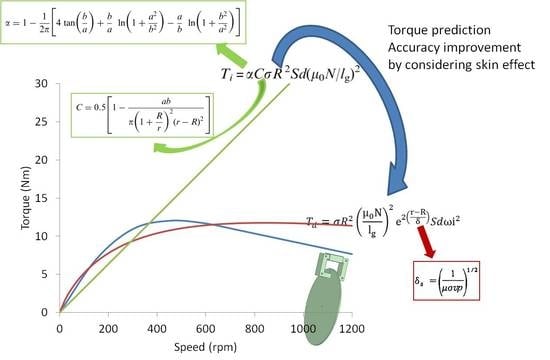
The braking torque can be determined from the power loss due to the eddy current divided by the rotating speed (). Equation (4) can only be used for the calculations under ideal conditions, in which under real circumstances, conductors have electrical resistance. As the actual braking torque is always calculated by applying this equation, it is necessary to add a correction factor that considers the eddy current turn path electrical resistance [17] and to consider it in the presence of magnetic field leakage [20]. Accordingly, the braking torque value can be calculated from the eddy current power loss using Equation (5), as given below:
where α is the effect of electrical resistance in the eddy current turn path area, and C implies that the flux leakage is a correction factor to approach the experimental value. Wouterse [17] was the first to propose a correction factor, C. This proposed work uses the same equation introduced by Lee [20], in which the cross-section of the pole shoe is rectangular. Meanwhile, the value of the correction factor can be calculated by applying the following equations [20].
3.2. Skin Effect Consideration
As reported by Lequesne [1], the braking torque at the ECB, which uses a non-magnetic material, will decrease after exceeding the critical speed, whereas in Equation (5), the relationship between the rotating speed and braking torque is linear. According to Smhyte [14], who asserted that the equation calculating torque is based on the eddy current power losses, this can only be used to calculate the torque at low speeds. At a higher speed, there will be a phenomenon of the skin effect, which causes the braking torque to change non-linearly. The skin effect is an influential factor, where the current density in the conductor will decrease exponentially in the area away from the surface [25]. With the influence of the skin, the effect will cause a decrease in the predicted torque value after exceeding the maximum torque. Therefore, by adding a skin effect variable to the braking torque calculation formula, the accuracy of the equation can be obtained. The influence of the skin effect occurs in the calculation of eddy currents generated in the induction process. The total eddy current that occurs in the volume that is affected by the skin effect can be calculated using the following equation [31]:
where is the eddy current value on the surface of the conductor, which is determined using the formula . The amount of eddy current differs along with the thickness of the conductor (d), based on Equation (8). Sharif [25] explained that the depth of the skin effect (δ) that occurs could be calculated using the equation , while the amount of braking torque can be calculated using the formula . Therefore, from Equation (4), the braking torque can be calculated by the following proposed equation.
The torque equation was previously applied to a cylindrical-shaped conductor in the magnetic field [25]. In this study, the skin effect calculation was employed on a rotating disk. The skin effects will not affect the thin conductors [26]. The eddy currents in the thick conductors will have a certain depth, and are thinner if the currents have high frequencies [38], as shown in Figure 2. For the tube conductors, the eddy currents at high current frequencies will form a mantle, as shown in Figure 2. In the next section, we will prove the effectiveness of adding skin effect factors to improve the accuracy of the braking torque calculation. In this second part of the braking torque calculation, the correction factor, which is due to the leakage of magnetic flux, was not included, because the design had a very narrow air gap. Another reason is that the ECB system design is different from that of previous studies [16], which used separate coils and winding cores. With an independent coil and core, it allows for a significant magnetic flux leakage. In this paper, the design of the coil core formed a loop with the coil core; hence, a tiny magnetic flux leakage occurred. In addition, the correction factor was not included in the calculation, because the conductors used in this paper had an excellent conductivity.
4. Methods
The main focus of the discussion in this paper is to obtain the calculation of the braking torque by observing the skin effect that is introduced in the proposed equation (refer to Equation (9)). To determine the effectiveness of the proposed equation, a comparison was carried out with the equation using the correction factor, as stated in Equation (5). The braking torque data used as a reference were the torque values obtained from 3D modelling and measurements in the experiments. The torque response generated in 3D modelling was used as a reference for comparing the result of the braking torque. The results of the torque calculation were compared with the torque from the 3D modelling results so as to determine the calculation performance of each equation. The analysis of the performance of the equation was undertaken by calculating the difference between the results using the root mean square error (RMSE). The smaller the RMSE value, the closer the approach value to the equation. Lastly, the torque value was compared using real tests so as to determine the level of closeness of the torque calculation results obtained. Details describing the settings of the 3D modelling and testing are explained in the following section.
4.1. Simulation
Modelling based on the finite element method (FEM) was conducted using the 3D modelling techniques in Maxwell software. The physical design of the ECB was undertaken using SolidWorks so as to facilitate the processing of the details, which were then imported into Maxwell 3D, as shown in Figure 1. The size and material properties used for filling the variables in the simulation can be seen in Table 1. The size determination was adjusted to suit the material available in the market. The diameter of the disc was determined based on the size of a conventional hydraulic disc brake for a two-wheeled motor. The material used was aluminum, so as to obtain high-value braking torque at low speeds. As for the coil core, it was designed using a transformer core consisting of sheets. The winding core used was made of iron (Fe). The working temperature in the disc and coil component was considered constant at a temperature of 30 °C. The modelling results are explained in the results and discussion section.
4.2. Experimental Setup
The experiments were conducted in the laboratory under controlled conditions. The ECB components were arranged in the scheme, as shown in Figure 3. The size of the design parameters was equal to the simulation parameters, as shown in Table 1. The disc was made of aluminum, while the winding core was taken from the transformer core. The mechanical energy used for braking employed an electric motor connected to a pulley. The current source used a voltage rectifier (Falcon 120E 900-Watt 120 E Inverter) with a fixed current regulation. The current flow was monitored using AC/DC clamp meters (Krisbow KW 0600491), and the braking force was measured using an aluminum single point load cell. The braking force measurement results were calculated to obtain the braking torque. Testing was performed on a controlled system. To avoid the influence of temperature, all of the data were taken shortly after the reference speed was reached.
A brushless DC electric motor (QS motor 3000 W 138 70 H) was used as the primary mover of the system. The motor drives the timing belt-pulley to move the conductor disk. In the stator section, the AC was converted to the DC using an inverter and a current regulator. During the current flows on the coil wire, magnetic flux was generated in the coil core, and it across the disc brake. The crossing magnetic flux on the disc brake generates a secondary current that causes secondary magnetic flux, with the opposite direction to the first. Therefore, an attractive force between the magnetic core and disc brake occurs. Thus, the load cell (KERN, CP 10-3PI) measured the net force produced, and the data were logged using the data acquisition (Arduino Uno, ATMEL AVR eight-bit). The braking torque was simply calculated from the measured load multiplied by the length of the stopper arm.
The data collection were conducted based on the preparation stage, followed by the setting time, in order to obtain the intended data retrieval parameters. After the retrieval of the data, a pause was initiated to restore the conditions to the initial parameters. The braking torque data were recorded for each rotational speed variation so as to avoid the effect of rising temperatures when operating. The time between collecting the data was used as a rest period or to stop, so that the uniformity of the conditions in each data collection could be obtained. The results of the torque measurements were then compared with the proposed equation, as shown in Figure 3. By simplifying and ignoring the data collection process, the torque measurements were performed on the conductor section, so the torque produced by the digester was not calculated, and the mechanical losses were not considered. The effect of temperature on the component was also neglected by shortening the adjustment time. By reducing the setpoint time, the temperature increased in the winding portion because of the material losses and discs as a result of the eddy current being ignored.
5. Result and Discussion
In this paper, a mathematical equation was used for the calculation of the braking torque using Simulink MATLAB (MathWork, Inc,. US). The calculation results were then compared with the torque values obtained by the 3D numerical analysis. Two braking torque equations were compared with the 3D models. The first equation was the calculation of the braking torque that used the correction factor, as given in Equation (5), and the equation that considered the skin effect is stated in Equation (9). To achieve an accurate mathematical model (refer to Equation (5)), which was built using Simulink MATLAB, it was compiled and tested using the data by Luo [21]. Their results were used to validate the Simulink code. Thus, the adjustment was used to predict the unstated variable so as to meet the equal value. The verified equations were then used to calculate the braking torque using the parameter model discussed in this paper. The mathematical model of the braking torque calculation was then modified by adding the effect of the skin effect, so as to obtain the proposed equation. The calculation results were then compared with the 3D modelling in order to determine the accuracy of the obtained calculation values. The design parameters used in this paper, as shown in Table 1, were determined based on the state of the braking disks available in the market.
3D Finite Element Method modelling was used as a reference (refer to Figure 1), in the form of a conductor disk and electromagnetic circuit. The design parameters were then applied, as stated in Section 4.1 of the simulation. The output data from the simulation were the braking torque with variations in speed, as shown in Figure 4. The value of the braking torque at the initial speed immediately showed a significant increase. It was because of the use of nonmagnetic materials with a low electrical resistance, so the generated eddy current was a considerable value. Here, the increase in braking torque will be smaller because of the increase in speed until obtaining the maximum torque. Even when the speed is increased, the braking torque will tend to decrease, which is due to the effect of the smaller value of the skin effect. The rotating speed of a conductor when the maximum torque is obtained is called the critical speed. To facilitate this discussion, the available speed was divided into low and high speeds, where the limit of both is critical speed.
Figure 4 shows the results of the modelling 3DFEM, which was undertaken to pass the critical speed. The maximum torque value was 12 Nm, which was obtained at the critical speed of 480 rpm. The discussion of the predictive performance obtained by the analytical equation was divided into an analysis at a low speed and an analysis on the performance of all of the conductor rotational variations. According to Wouterse [17], equations that use correction factors are only effective for braking analysis at low-speed braking. Therefore, by using analyses at low and high speeds, this will attain an overview of the results of the calculations and simulations at low speeds as well as accuracy, while the comparison of the high torque will show the deviation resulting from the calculations and consistency to produce the braking torque.
5.1. Braking Torque at Low-Speed Calculation Using a Correction Factor
The braking torque calculation in this subsection was achieved by adding the correction factor, as given in Equation (5), while the correction factor was calculated using Equations (7) and (8). In Equation (8), it can be seen that the effect of the turn path resistance is calculated using fixed design parameters. The same occurs in the calculation of Equation (7), which influences the flux leakage. As such, the equation added by the correction factor will only change linearly. Moreover, based on the calculations of Equations (7) and (8), the values of each correction factor are fixed, namely α = 6.285 and C = 0.49. In the calculation of torque (Equation (5)), it can be seen that the torque value is proportional to the magnitude of the conductor rotation, so that the change in torque is proportional to the magnitude of the change in speed, as shown in Figure 5. As the results of the equation produce a linear value, the calculation of the braking torque using the correction factor does not have maximum torque or maximum torque of infinite value. The discussion in this section is limited to low speeds only, and this is to illustrate that the use of correction factors is only effective in that area. Here, Figure 5 is limited to only 480 rpm, or to the critical speed of the results. At the initial speed, the calculated braking torque was smaller than the simulation results. When approaching the critical speed, the predicted value of the equation exceeded the value of the simulation results. Figure 5 shows that the equation using the correction factor still produces a good predictive value on low-speed torque calculations, although the calculation results obtained were linear where the resulting value was different from the reference value. This is supported by taking into account the RMSE value, which is almost the same value when compared to the proposed equation. A full explanation will be discussed in the next section.
5.2. Braking Torque at Low-Speed Calculation with Skin Effect Consideration
The calculation of the braking torque at a low speed regarding the skin effect was calculated using Equation (9). The skin effect of concern in this discussion only affected the eddy current calculation that occurred in the conductor. The eddy current, which is affected by the skin effect, was calculated using Equation (8). The rotational speed influenced the formula in the calculation of the skin effect, causing the calculation of the braking torque by paying attention to the skin effect, which produces an equation whose exponential value is shown in Figure 6. Upon reaching the maximum speed, increasing the rotational speed decreased the value of the torque produced. The value of the braking torque obtained was close to the value of the results of the 3D modelling, because the resulting graphic patterns were similar. Although it had an exponential pattern, the critical speed value obtained was greater than the modelling. Still, in Figure 6, at 480 rpm, the torque still showed a positive gradient. The braking torque that resulted from the proposed model had lower values at the initial speed, with a lower difference. The torque value increased at the higher speed, exceeding the modelling result. Compared with the computation of torque, which only considered the correction factor, the proposed equation exhibited better results.
5.3. Braking Torque Performance Comparison
A comparison of the braking torque results of Equation (5) and the proposed equation compared to the modelling at low and high speeds is discussed in this section. This result is due to the use of a non-magnetic material affecting the low critical speed, so that on its application, the ECB will also work in high-speed areas. Figure 7 shows a comparison of the braking torque using 3DFEM modeling (Ansys Maxwell, Ansys. Inc., USA) as well as the results of the mathematical analysis on all of the speed variations. Figure 7 shows the predicted value of the braking performance using Equation (5), resulting in a more significant error at both low and high speeds compared with the proposed equation. As Equation (5) produces a linear equation, the produced maximum torque will be infinite, whereas the results obtained by the proposed equation approach give the exponential value of the reference value.
Figure 7 shows a comparison of the predicted torque among three models generated by the ECB. Of the three techniques, the use of the formulations that consider the correction factor shows a difference. The formula that uses the correction factor produced a maximum infinite braking torque, so that it does not have a critical speed. However, as a reference, the 3D simulations produced a maximum torque of 12 Nm, whereas the calculation results gave a value of 11.75 Nm. On the other hand, the results of the calculations using the proposed equation gave a small difference in the calculation results of 0.25 Nm or 2.7% of the results of the 3D simulation, although there were critical speed differences produced by both. To determine the performance of both formulations, the value difference analysis was used, as listed in Table 2. The difference value was calculated at each torque value calculated against the torque of the simulation results at each speed. The smaller RMSE value indicated the smaller calculation error of the reference value.
The performance of the calculation results, as shown in Table 2, is explained next. The RMSE calculation results that were obtained were almost similar at low speeds. The equation using the correction factor is suitable for low-speed calculations, because the RMSE obtained was quite small, being 1.78 Nm. This value was not much different from the RMSE proposed equation of 1.16 Nm. The difference between the two values is tiny, only 0.62 Nm. At high speeds, Equation (5) produced significant braking torque errors with a total RMSE amount of 14.63 Nm or an increment of about 12.85 Nm compared with the total RMSE at a low speed only. It is in contrast to the proposed equation, which has an RMSE value of 1.79 Nm, or an increment of 0.63 Nm from the low-speed calculations. The difference between the two RMSE equations is 12.84 Nm. It is clear from the observations of the calculation results both in the trend calculation results and the difference in value, that the formula that uses the correction factor is only suitable for low speeds. The formulation that considers the skin effect gives a prediction that is closer to the torque for the low and high speeds. To further provide a solid foundation, experimental testing was conducted to obtain data on real measurements.
5.4. Experimental Validation
Real testing was intended to provide a real picture of the results of the calculation of the braking torque. The most important part of the data comparison was for determining the maximum torque value generated by the ECB. Tests were carried out with restrictions after obtaining the maximum torque value, for instance, considering the maximum speed that could be obtained by a motorcycle in general, and then with limited testing at speeds lower than 1000 rpm. Figure 8 shows a comparison of the braking torque by measuring the experiment and the proposed equation. The maximum value of the torque produced in the real test was 11.99 Nm, resulting in a difference of 0.25 Nm or 2.08% compared to the proposed equation. However, the resulting critical speed of the experiment was obtained at a lower value. The test results were then compared with the proposed equation, showing an RMSE value of 0.65 Nm and an average error of 4.9%.
The use of the proposed equation shows an increase in the value of accuracy that can be seen from the small difference in the maximum torque and a low RMSE. The maximum torque prediction value is very close to 2.7% when compared with the 3D modelling, and 2.08% when compared to the real testing, although there were some biases in critical speed region. A comparison of the resulting torque patterns at variations in speed was obtained using a small RMSE value. The RMSE value, when compared to the simulation, was 1.79 Nm, and even smaller when compared with the real test of 0.65 Nm. The low RMSE value indicates the close prediction value at each point produced. The use of torque calculations considering the skin effect is proven to provide better accuracy compared with the equation using only correction factors.
6. Conclusion
In this paper, braking torque prediction analysis for unipolar axial type ECB was adopted. The braking torque was calculated based on the eddy current power loss. When approaching the actual results, the braking torque equation was modified by introducing a correction factor. However, the results of the analysis showed that the performance was only good at low speeds. To improve the approach, the effect of the skin effects was added in the calculation of the braking torque. As a reference, a calculation result for adopting the braking torque using 3D modelling was used. At a low speed, the RMSE value of the equation with a correction factor was 1.76 Nm, while the equation with the skin effect was 1.16 Nm. Even for the entire calculation of the correction factor, it reached the RMSE of 14.63 Nm, while the skin effect equation was 1.79 Nm. The maximum value of the torque at the same air gap was obtained closer to the value of 12.00 Nm for the proposed equation, and 11.75 Nm with a close critical speed value. For further research, it is necessary to prove the accuracy of the equation by observing the change in temperature. It is also necessary to prove the equation for a set system with dynamic braking.
Author Contributions
Conceptualization, H.T.W.; methodology, H.T.W.; software, H.T.W.; validation, H.T.W.; formal analysis, H.T.W and U.U.; investigation, H.T.W.; resources, H.T.W.; data curation, H.T.W.; writing—original draft preparation, H.T.W.; writing—review and editing, U.U. and M.A.; visualization, H.T.W.; supervision, D.D.D.P.T. and M.N; project administration, M.N.; funding acquisition, M.N. All authors have read and agreed to the published version of the manuscript.
Funding
This work was funded by the Ministry of Research, Technology, and Higher Education of the Republic of Indonesia, through contract no. 208/SP2H/LT/DPRM/2019. This research is partially funded by the Indonesian Ministry of Research, Technology, and Higher Education, under the World Class University Program, managed by the Institute of Technology Bandung, Indonesia.
Conflicts of Interest
The authors declare no conflict of interest.
References
- Lequesne, B.; Liu, B.; Nehl, T.W. Eddy-current machines with permanent magnets and solid rotors. IEEE Trans. Ind. Appl. 1997, 33, 1289–1294. [Google Scholar] [CrossRef]
- Baharom, M.Z.; Nuawi, M.Z.; Priyandoko, G.; Harris, S.M. Eddy current braking experiment using brake disc from aluminium series of A16061 and A17075. IOP Conf. Ser. Mater. Sci. Eng. 2012, 36, 12005. [Google Scholar] [CrossRef]
- Shi, T.; Wang, D.; Li, Z.; Zheng, D. Modeling of disk-type permanent magnet eddy-current driver based on soft measurement method and performance analysis. Int. J. Appl. Electromagn. Mech. 2016, 50, 525–535. [Google Scholar] [CrossRef]
- Kou, B.; Jin, Y.; Zhang, H.; Zhang, L.; Zhang, H. Modeling and Analysis of Force Characteristics for Hybrid Excitation Linear Eddy Current Brake. IEEE Trans. Magn. 2014, 50. [Google Scholar] [CrossRef]
- Ma, J.; Zhang, B.; Huang, X.; Fang, Y.; Cao, W. Design and analysis of the hybrid excitation rail eddy brake system of high-speed trains. J. Zhejiang Univ. A 2011, 12, 936–944. [Google Scholar] [CrossRef]
- Kou, B.; Jin, Y.; Zhang, H.; Zhang, L.; Zhang, H. Analysis and Design of Hybrid Excitation Linear Eddy Current Brake. IEEE Trans. Energy Convers. 2014, 29, 496–506. [Google Scholar]
- Baran, W.K.A. Influence of Different Magnetic Field Profiles on Eddy-Current Braking. IEEE Trans. Magn. 1970, 6, 260–263. [Google Scholar] [CrossRef]
- Yazdanpanah, R.; Mirsalim, M. Analytical study of axial-flux hybrid excitation eddy current brakes. Int. J. Appl. Electromagn. Mech. 2015, 47, 885–896. [Google Scholar] [CrossRef]
- Waloyo, H.; Nizam, M.; Tiahiana, D. Parametric Design in Single Disk Axial Eddy Current Brake. In Proceedings of the 2018 5th International Conference on Electric Vehicular Technology (ICEVT), Surakarta, Indonesia, 30–31 October 2018; pp. 132–135. [Google Scholar]
- Lubin, T.; Rezzoug, A. 3-D Analytical Model for Axial-Flux Eddy-Current Couplings and Brakes Under Steady-State Conditions. IEEE Trans. Magn. 2015, 51. [Google Scholar] [CrossRef] [Green Version]
- Albertz, D.; Dappen, S.; Henneberger, G. Calculation of the 3D non-linear eddy current field in moving conductors and its application to braking systems. IEEE Trans. Magn. 1996, 32, 768–771. [Google Scholar] [CrossRef]
- ZhiDing, Y.; Long, F.Y.; Fu, X.X.; Wei, S.; Yang, C. Analysis of Two-Dimensional and Three-Dimensional Simulation of the Disc Eddy Current Braking Device. Adv. Mater. Res. 2012, 516–517, 553–557. [Google Scholar]
- Labbe, N.; Marechal, Y.; Meunier, G.; Harara, H.B. 2D nonlinear finite element modelling of electromagnetic retarders using time-stepping algorithms, and the Petrov-Galerkin method with homogenization techniques. IEEE Trans. Magn. 1996, 32, 772–775. [Google Scholar] [CrossRef]
- Smythe, W.R. On eddy currents in a rotating disk. Electr. Eng. 1942, 61, 681–684. [Google Scholar] [CrossRef]
- Schieber, D. Unipolar induction braking of thin metal sheets. Proc. Inst. Electr. Eng. 1972, 119, 1499. [Google Scholar] [CrossRef]
- Schieber, D. Braking torque on rotating sheet in stationary magnetic field. Proc. Inst. Electr. Eng. 1974, 121, 117. [Google Scholar] [CrossRef]
- Wouterse, J.H. Critical torque and speed of eddy current brake with widely separated soft iron poles. IEE Proc. B Electr. Power Appl. 1991, 138, 153. [Google Scholar] [CrossRef]
- Simeu, E. Application of NARMAX modelling to eddy current brake process. In Proceedings of the International Conference on Control Applications, Albany, NY, USA, 28–29 September 1995; pp. 444–449. [Google Scholar]
- Simeu, E.; Georges, D. Modeling and control of an eddy current brake. Control Eng. Pract. 1996, 4, 19–26. [Google Scholar] [CrossRef]
- Lee, K.; Park, K. Optimal robust control of a contactless brake system using an eddy current. Mechatronics 1999, 9, 615–631. [Google Scholar] [CrossRef]
- Luo, L.; Zhai, Q.; Li, W.; Qian, C.; Liu, H. Research on an integrated electromagnetic auxiliary disc brake device for motor vehicle. IEEJ Trans. Electr. Electron. Eng. 2017, 12, 434–439. [Google Scholar] [CrossRef]
- Singh, A. Theory of eddy-current brakes with thick rotating disc. Proc. Inst. Electr. Eng. 1977, 124, 373. [Google Scholar] [CrossRef]
- Zhang, B.; Peng, T.; Chen, Q.; Cao, Q.L.; Ji, K.; Shuang, B.; Ye, J.J.; Li, L. 3-D nonlinear transient analysis and design of eddy current brake for high-speed trains. Int. J. Appl. Electromagn. Mech. 2012, 40, 205–214. [Google Scholar] [CrossRef]
- Karakoc, K.; Suleman, A.; Park, E.J. Optimized Braking Torque Generation Capacity of an Eddy Current Brake With the Application of Time-Varying Magnetic Fields. IEEE Trans. Veh. Technol. 2014, 63, 1530–1538. [Google Scholar] [CrossRef]
- Sharif, S.; Sharif, K. Influence of skin effect on torque of cylindrical eddy current brake. In Proceedings of the 2009 International Conference on Power Engineering, Energy and Electrical Drives, Lisbon, Portugal, 18–20 March 2009; pp. 535–539. [Google Scholar]
- Conraths, H.-J. Eddy current and temperature simulation in thin moving metal strips. Int. J. Numer. Methods Eng. 1996, 39, 141–163. [Google Scholar] [CrossRef]
- Siakavellas, N.J. Two simple models for analytical calculation of eddy currents in thin conducting plates. IEEE Trans. Magn. 1997, 33, 2245–2257. [Google Scholar] [CrossRef]
- Sinha, G.; Prabhu, S.S. Analytical model for estimation of eddy current and power loss in conducting plate and its application. Phys. Rev. Spec. Top. Accel. Beams 2011, 14, 1–10. [Google Scholar] [CrossRef]
- Waloyo, H.; Ubaidillah, U.; Tjahjana, D.D.D.P.; Nizam, M.; Koga, T. Mini review on the design of axial type eddy current braking technology. Int. J. Power Electron. Drive Syst. 2019, 10, 2198. [Google Scholar] [CrossRef]
- Edwards, J.D.; Jayawant, B.V.; Dawson, W.R.C.; Wright, D.T. Permanent-magnet linear eddy-current brake with a non-magnetic reaction plate. IEE Proc. Electr. Power Appl. 1999, 146, 627. [Google Scholar] [CrossRef]
- Jhonshon, W.C. Transmission Lines and Networks; McGraw-Hill: New York, NY, USA, 1950. [Google Scholar]
- Kazimierczuk, M. High-Frequency Magnetic Components; John Wiley & Sons, Ltd.: Chichester, UK, 2013. [Google Scholar]
- Aizawa, Y.; Nakayama, H.; Kubomura, K.; Nakamura, R.; Tanaka, H. Theoretical study on lowering loss of skin effect suppressed multi-layer transmission line with positive/negative (Cu/NiFe) permeability materials for high data-rate and low delay-time I/O interface board. AIP Adv. 2020, 10, 15124. [Google Scholar] [CrossRef]
- Boglietti, A.; Cavagnino, A.; Ferraris, L.; Lazzari, M. Skin effect experimental validations of induction motor squirrel cage parameters. COMPEL Int. J. Comput. Math. Electr. Electron. Eng. 2010, 29, 1257–1265. [Google Scholar] [CrossRef]
- Akbaba, M.; Fakhro, S.Q. New model for single-unit representation of induction motor loads, including skin effect, for power system transient stability studies. IEE Proc. B Electr. Power Appl. 1992, 139, 521. [Google Scholar] [CrossRef]
- Tang, B.; Lin, Q.; Li, B. Research on Thermal Stress by Current Skin Effect in a Railgun. IEEE Trans. Plasma Sci. 2017, 45, 1689–1694. [Google Scholar] [CrossRef]
- Zhang, D. Magnetic skin effect in silicon-iron core at power frequency. J. Magn. Magn. Mater. 2000, 221, 414–416. [Google Scholar] [CrossRef]
- Jiao, S.; Liu, X.; Zeng, Z. Intensive Study of Skin Effect in Eddy Current Testing With Pancake Coil. IEEE Trans. Magn. 2017, 53, 6201608. [Google Scholar] [CrossRef]
Figure 1.
Unipolar axial type eddy current brake (ECB): (a) 3D model in general structure, (b) eddy current and design variable and (c) air gap in cross section area.
Figure 1.
Unipolar axial type eddy current brake (ECB): (a) 3D model in general structure, (b) eddy current and design variable and (c) air gap in cross section area.

Figure 2.
Skin effect illustration in low and high frequency.

Figure 3.
Experimental setup.

Figure 4.
3D finite element method (FEM) braking torque.

Figure 5.
Low-speed correction factor braking torque.

Figure 6.
Low-speed skin effect braking torque.

Figure 7.
Braking torque in total.

Figure 8.
Experimental comparison.


Table 1.
Eddy Current Brake design parameters.
| Variable | Unit | Value |
|---|---|---|
| Current (i) | A | 20 |
| Number of turns (N) | − | 360 |
| Length of pole shoe (a) | mm | 30 |
| Width of pole shoe (b) | mm | 12.5 |
| the total length of the winding core (l) | mm | 248 |
| Distance from center to pole shoe center (r) | mm | 83.5 |
| Air gap (t) | mm | 0.5 |
| Disc thickness (d) | mm | 5 |
| The radius of disk brake (R) | mm | 120 |
| Relative permeability of aluminum (μAl) | − | 1.000022 |
| Relative permeability of iron (μFe) | − | 400 |
| The conductivity of aluminum (α) | Ωm | 2.06 × 10⁻⁷ |
Table 2.
Performance comparison. RMSE—root mean square error.
| Torque Equation | Low Speed | All Speed | ||
|---|---|---|---|---|
| Average Error (Nm) | Root Mean Square Error (Nm) | Average Error (Nm) | Root Mean Square Error (Nm) | |
| Equation (5) (correction factor) | −0.73 | 1.78 | 9.95 | 14.63 |
| Proposed equation (skin effect) | −0.83 | 1.16 | 0.61 | 1.79 |
© 2020 by the authors. Licensee MDPI, Basel, Switzerland. This article is an open access article distributed under the terms and conditions of the Creative Commons Attribution (CC BY) license (http://creativecommons.org/licenses/by/4.0/).
Share and Cite
MDPI and ACS Style
Waloyo, H.T.; Ubaidillah, U.; Tjahjana, D.D.D.P.; Nizam, M.; Aziz, M. A Novel Approach on the Unipolar Axial Type Eddy Current Brake Model Considering the Skin Effect. Energies 2020, 13, 1561. https://doi.org/10.3390/en13071561
AMA Style
Waloyo HT, Ubaidillah U, Tjahjana DDDP, Nizam M, Aziz M. A Novel Approach on the Unipolar Axial Type Eddy Current Brake Model Considering the Skin Effect. Energies. 2020; 13(7):1561. https://doi.org/10.3390/en13071561
Chicago/Turabian StyleWaloyo, Hery Tri, U Ubaidillah, Dominicus Danardono Dwi Prija Tjahjana, Muhammad Nizam, and Muhammad Aziz. 2020. "A Novel Approach on the Unipolar Axial Type Eddy Current Brake Model Considering the Skin Effect" Energies 13, no. 7: 1561. https://doi.org/10.3390/en13071561
Note that from the first issue of 2016, this journal uses article numbers instead of page numbers. See further details here.