Fluid Selection of Transcritical Rankine Cycle for Engine Waste Heat Recovery Based on Temperature Match Method


1
State Key Laboratory of Engine Reliability, Weichai Power Co., Ltd., Weifang 261001, China
2
State Key Laboratory of Engines, Tianjin University, Tianjin 300072, China
3
Department of Thermal Science and Energy Engineering, University of Science and Technology of China, Hefei 230027, China
*
Author to whom correspondence should be addressed.
Energies 2020, 13(7), 1830; https://doi.org/10.3390/en13071830
Submission received: 6 March 2020
/
Revised: 7 April 2020
/
Accepted: 8 April 2020
/
Published: 10 April 2020
(This article belongs to the Section F: Electrical Engineering)
Abstract
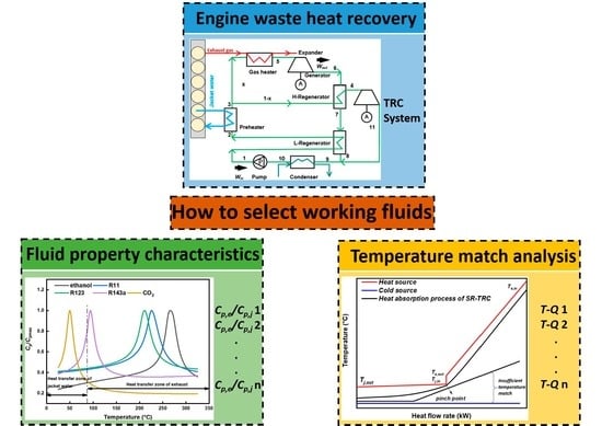
:Engines waste a major part of their fuel energy in the jacket water and exhaust gas. Transcritical Rankine cycles are a promising technology to recover the waste heat efficiently. The working fluid selection seems to be a key factor that determines the system performances. However, most of the studies are mainly devoted to compare their thermodynamic performances of various fluids and to decide what kind of properties the best-working fluid shows. In this work, an active working fluid selection instruction is proposed to deal with the temperature match between the bottoming system and cold source. The characters of ideal working fluids are summarized firstly when the temperature match method of a pinch analysis is combined. Various selected fluids are compared in thermodynamic and economic performances to verify the fluid selection instruction. It is found that when the ratio of the average specific heat in the heat transfer zone of exhaust gas to the average specific heat in the heat transfer zone of jacket water becomes higher, the irreversibility loss between the working fluid and cold source is improved. The ethanol shows the highest net power output of 25.52 kW and lowest electricity production cost of $1.97/(kWh) among candidate working fluids.
1. Introduction
Internal combustion engines (ICEs) are important power sources and are responsible for around 60% of all oil produced [1]. However, the brake thermal efficiency and fuel economy of current engines are still quite low. One of the reasons that limit further improvement is that part of the heat energy from fuel combustion is wasted to the ambient through multiple media such as exhaust gas, jacket water, turbo-charge coolant, exhaust gas recirculation coolant, etc. [2]. Hence, great potential in engine waste heat recovery has been put forward and widely concerned if the waste heat can be transformed into mechanical or electricity power. The Rankin cycle (RC) is supposed to be a promising bottoming cycle technology when engine waste heat recovery is set as the topping cycle [3].
Many researches about RCs are devoted in biomass [4], solar power plants [5], geothermal [6], industrial waste heat [7], combined heat and power generation [8], etc. As for the RCs applied to the engine waste heat recovery, the first study proposed may be traced to the 1970s when Patel et al. [9] compounded the truck diesel engine with a bottoming cycle of the subcritical organic Rankine cycle (ORC) system. A great improvement of 15% in fuel economy assumption was achieved by means of the aforementioned conceptual design. Since then, the subcritical ORC technologies were shown as exceptional and effective features for the characteristics of small volume, light weight, low cost, no invasive property compared with turbo-compounding, energy efficiency improvement, and environmental protection [10] and attracted a widespread attention. When different organic working fluids are adopted, the performances of ORCs vary. Rad et al. [11] selected potential working fluids for ORCs in industrial waste heat recovery under various heat source temperatures. It could be deduced that when the critical temperature of working fluids such as water was near the heat source temperature, the highest energy efficiency could be achieved mainly due to a lower temperature difference between the heat source and working fluid. Mikielewicz et al. [12] conducted thermodynamic performances of an ORC system with various working fluids integrated with a 900 MWe power plant. They recommended ethanol, the best-performing working fluid with the highest exergetic efficiency of 78.90%. Akbari et al. [13] focused on a newly designed systematic selection approach of the optimal working fluid in order to minimize the total thermal conductance of the system. They found that c2butene needs the smallest heat exchanger surface area compared to R600a, R601a, and R245fa. Nevertheless, the working fluids used in the conventional subcritical ORCs with their critical temperatures less than the temperature of the heat source will present poor system performances. The reason can be explained by large irreversibility between the working fluid and heat source caused by the isothermal phase change of the working fluid [14].
Various investigations have been performed in the literature for minimizing the aforementioned large irreversibility, as well as decreasing the exergy destruction of the system, which results in a higher performance. The utilization of zeotropic mixtures serves as a potential solution. It is found that a temperature glide occurs in the phase change procedure for zeotropic mixtures, which contributes to a better temperature-matching performance and the enhancement of net power and exergy efficiency. Zhi et al. [15] studied ORCs with R600a/R601a and R134a/R245fa mixtures as working fluids in engine waste heat recovery. The maximum increase of 19.78% in power output (97.95 kW) could be obtained with the mixtures of R600a/R601a (0.3/0.7) and R134a/R245fa (0.4/0.6) compared with pure working fluids. Andreasen et al. [16] conducted four different methods to make comparisons of selected 30 different pure fluids and zeotropic mixtures on heat exchanger performances and illustrated the benefits of using zeotropic mixtures. Interesting results showed that net power outputs of zeotropic mixtures could be improved by up to 13.6% compared to the best pure working fluids when the same minimum pinch point temperature differences for all fluids were taken into consideration. Similar research on zeotropic mixtures by Zühlsdorf et al. [17] in heat pumps revealed that a simultaneous improvement of thermodynamic performance and levelized specific cost could be achieved when the mixture of 30% propylene and 70% R-1234ze(Z) was adopted in the case study since the mixture showed a better temperature match with the temperature profile of the sink and source during their heat transfer. Chys et al. [18] investigated zeotropic mixtures in a geothermal power plant, and they found a great increase in energy efficiency of approximately 16% and 6% under 250 and 150°C heat source temperatures when the zeotropic mixture was compared with pure fluid. Lecompte et al. [19] conducted exergetic analysis of an ORC system considering various composition mixtures. The maximum exergetic efficiency of 32.05% could be achieved when the isobutane–isopentane with a concentration of 0.81/0.19 was selected as the optimal composition. The results were mainly ascribed to decreasing the exergy destruction in the condenser.
The transcritical Rankine cycle (TRC), another potential solution to the temperature match problem, is introduced to improve the temperature match between the working fluid and heat source. Hence, the comparison between the subcritical ORC and TRC is carried out. Hsieh et al. [20] conducted an experimental comparison of five cases when the working fluid R218 was pressurized to the subcritical or supercritical states. Apparent increases in the mass flow rate and heat absorption rate were found when the TRCs were achieved. Tian et al. [21] evaluated the performance of a TRC system considering the thermophysical properties of the working fluid and presented a selection principle of working fluids under different heat source temperatures. Shu et al. [22] conducted a theoretic analysis on a dual-loop TRC system in an engine waste heat recovery to overcome the large temperature differences between the high-temperature exhaust gas and low-temperature engine jacket water. Six candidate working fluids were compared and analyzed. Li et al. [23] proposed a novel configuration coupling the supercritical and subcritical heat absorption processes to increase the heat-power conversion efficiency and to improve the adaptability to heat sources. Meng et al. [24] conducted a thermoeconomic performance comparison between the TRC and ORC in a low-temperature heat source utilization. The authors found that the net power output could be improved by 128.5% at maximum for the TRC and considered it a great potential in low-temperature heat source recovery due to its good environmental properties.
In addition to cycle comparison and configuration modification, a key design factor of the TRCs is the working fluid selection. Recently, a growing number of scholars have devoted their efforts to selecting the best working fluid from numerous candidates in the specific application area considering various optimization objectives. On one hand, when the operation stability and compatibility with materials of different working fluids are investigated as criteria, several indicators are included, mainly considering the working fluid properties. Liu et al. [25] firstly proposed concepts of dry, wet, and isentropic working fluids classified by the positive, negative, and infinite slope of the T-s curve, respectively. Further assertion was given by Hung et al. [26] that isentropic or dry fluids were suggested to avoid liquid droplet impingement in the turbine blades during the expansion. One solution to the use of wet working fluids was given by Desai et al. [27] to ensure the superheated state at the turbine inlet. On the other hand, when the thermodynamic performances of different working fluids are studied, a brief review is also given below. The critical temperature of different working fluids showed great impacts on system thermodynamic performances. Heberle et al. [28] compared the second law of efficiency of various fluids and recommended that the working fluids with high critical temperatures like isopentane were suitable for the ORCs. Similar results could be found when the boiling temperatures of fluids were compared. Actually, the relations between the critical temperature and boiling temperature were given by Joback [29] that the boiling temperature became higher if the critical temperature became higher for the fluids in the same fluid family. Besides the critical temperature, the ratio of latent heat to sensible heat is commonly used and modified to evaluate exergetic performances of working fluids. The specific heat of a working fluid is an important property, since the direct impact is caused by different values of specific heats on the pressurization and expansion processes. Maizza and Papadopoulos et al. [30,31] believed that the lower specific heat would decrease the work consumed by the pump and increase the power output indirectly. Furthermore, a higher specific heat was better-suited to obtain large expansion work. Stijepovic et al. [32] observed that working fluids with a low ratio of latent heat to sensible heat, which would be inclined to extract more heat from the heat source, showed better performances regarding exergy efficiency. A combination of the defined Jakob number and the average temperature between the evaporation temperature and condensation temperature was deduced by Su et al. [33]. They recommended it as more favorable for system thermal efficiency when a smaller Jakob number was achieved. The molecular complexity and molecular weight of different working fluids also has an impact on the system thermodynamic performance, especially on the expansion process [34]. As for the environmental aspects, the main concerns included the ozone depletion potential (ODP), global warming potential (GWP), and the atmospheric lifetime (ALT).
After a concise literature review about different performances of working fluids in TRCs and fluid selection instructions, it is concluded that the way to improve the temperature match between working fluids and thermal sources such as zeotropic mixtures and cycle modification shows a great impact on systems’ performances. In addition, the reason why different thermodynamic performances of different working fluids are performed can be derived from the multiple properties of working fluids. Nevertheless, a current limitation of the reviewed working fluid selection is that a sufficient selection condition of what kind of properties the best working fluid possesses is proposed only after the comparison of their thermodynamic or economic performances. It seems to show a lack of active fluid selection instruction from the perspective of what kind of properties better-working fluids should possess. Additionally, the thermodynamic and economic performances of selected working fluids are served as a validation of the active fluid selection instruction. Hence, based on the temperature match method, which has been proved to be an effective and efficient way to achieve configuration modification, an optimal TRC layout is proposed to accomplish the active working fluid selection. The illustration and validation of the approach will allow the development of selecting working fluids actively from another dimension. Hence, the aim of the study is twofold: (i) set up a temperature match method-based working fluid selection instruction to obtain better working fluid properties with better temperature match performances between the bottoming system and multiple engine heat sources, as well as the cold source, and (ii) conduct a thermodynamic and economic analysis to validate the proposed method and optimize important operation parameters.
2. System Descriptions
2.1. Heat Sources
In this paper, a 6-cylinder diesel engine in-line with a 2-stage turbocharger and intercooler for heavy-duty trucks was selected for waste heat recovery [35]. The heat balance test of the diesel engine without a waste heat recovery system was conducted to investigate the amount of recoverable heat. The major parameters of the target diesel engine are listed in Table 1. The air fuel ratio for the diesel engine is usually a variable to optimize combustion, leading to the change of exhaust gas composition under different engine loads, as shown in Table 2. The constituent part and mass fraction of the exhaust compositions under the design condition of 1300rpm and 1279 N·m are set as: CO2 = 15.2%, H2O = 6.0%, N2 = 73.0%, and O2 = 5.8%. Additionally, detailed parameters of waste heat sources and engine design conditions are shown in Table 3. According to the heat balance test, the exhaust gas temperature reached 469.4°C, whereas the mass flow rate of the jacket water reached 2.42 kg/s under the operation conditions of 1300 rpm and 1279 N·m, which were dominated by various waste heat sources and should be recovered primarily.
2.2. TRC Configuration
In this research, a split dual regenerative transcritical Rankine cycle (SR-TRC) is investigated shown in Figure 1. Due to the design of split branches and two regenerators, the SR-TRC system can meet the requirement of recovering the jacket water and exhaust gas simultaneously and improve the temperature matching in the whole heat absorption process, and has been proved to be a novel cycle configuration to achieve better temperature match between the system and heat sources [36]. The concrete working process of SR-TRC is: the working fluid transferring heat from jacket water in the preheater (2-3) is split into two parts, namely, high-temperature branch (H-branch) and low-temperature branch (L-branch). The working fluid in H-branch completely absorbs waste heat from exhaust gas in the gas heater (3-5) and then generates power in the expander-generator (5-6), whereas the working fluid in L-branch streams through H-regenerator (3-4) to absorb heat after expansion and then generates power (4-11). After the working fluid of H-branch streams through the H-regenerator (6-7), there still exists recoverable heat to be utilized. Thus, the L-regenerator (7-8) is designed to heat the working fluid (1-2) after pressurization (10-1). The working fluid in both branches enters condenser (9-10) to regain the capability to work after their convergence (8-9 and 11-9).
3. Mathematical Modeling
The study is performed by means of a thermodynamic and economic analysis focusing on the energetic, exergetic, and economic performances. Several reasonable assumptions below are defined to simplify the computation process [37,38,39]: (1) each component and operating point is under equilibrium and in a steady-state condition; (2) heat losses and pressure losses are neglected in the pipes and in all components; (3) the isentropic efficiencies of the expander, pump, and generator are assumed to be 0.7, 0.8, and 0.9, respectively; (4) the changes in the kinetic and potential energy of the fluids can be neglected; (5) the pinch point temperature differences (Tpp) in the gas heater, preheater, and regenerator are set to be 30 °C, 5 °C, and 15 °C; and (6) temperatures of the condensation process and the ambient are set at 25 °C to guarantee that CO2 can be condensed stably during the phase change process. The properties of the working fluid are derived from the REFPROP-NIST [40].
3.1. Thermodynamic Analysis
Thermodynamic modeling of the combined system can be constituted by the energetic and exergetic terms. Based on the first law of thermodynamics, the energy balance equations of the system components are listed in the second column of Table 4. An exergy analysis based on the second law of thermodynamics is necessary to judge the irreversibility of each component during the investigation of the cycles. The exergy loss equations of the system components are listed in the third column of Table 4. To make full use of one heat source at least, the mass flow rate () of the working fluid is dependent on the minimum value of and , which are calculated by:
In order to ensure the stable operation of the heat exchanger, the outlet temperature of the exhaust gas from the gas heater should not be lower than the acid dew point temperature (120 °C) to prevent the corrosion of the heat exchanger [39]. In addition, the outlet temperature of the jacket water after the preheater should be higher than the returned temperature to avoid an unnecessary impact on the engine operation. Based on the aforementioned conditions, the heat recovery efficiency and system total efficiency are defined as:
3.2. Economic Analysis
Considering the characteristics of the heat exchanger-based split cycles, the heat transfer areas of the heat exchangers are calculated by:
where K is the total heat transfer coefficient of the heat exchanger, and Δt is the log mean temperature difference (LMTD) between the hot side and the cold side.
To determine the unit cost of the streams in the conversion system, the capital cost according to the economic situation in the year 2014 is expressed as:
where CEPCI2001 = 382 and CEPCI2014 = 586.77 (CEPCI means chemical engineering plant cost index).
The purchased cost Cp and the cost factor Fbm are two main parameters that affect the base investment cost of each component. Here, the Cp is calculated by the capacity of the components, and the relevant coefficient K, and the cost factors, including direct project expenses, contingency and contractor fees, indirect project expenses, and the auxiliary facilities, are taken into consideration by Fbm. The relevant investment models and coefficients according to [41] are listed in Table 5. In addition, the capital recovery (CRF) is estimated as:
where i is the interest rate, and the value is set to be 5%; time is the economic lifetime, and its value is set to 15 years. The annuity of the investment Ank can be expressed as:
The electricity production cost (EPC) can be calculated by the equation:
where fk is the operation, maintenance, and insurance cost factor, and its value is 1.65%; h is the operation hours of a year, and its value is set to be 2190 h considering the practical operation.
The aforementioned calculations were conducted through MATLAB. To help readers get a good grasp of the calculation and optimization procedure, the flow chart is given in Figure 2.
3.3. Model Validation
The model of the transcritical Rankine cycle system with a preheater and a regenerator was verified with the same operating parameters as in reference [42], and the comparison results are listed in Table 6 based on the thermodynamic analysis as follows. A 25-MW gas turbine was used as the heat source under a condensing temperature Tcond of 20 °C and a expander inlet temperature Texpander of 391 °C. The RD (relative deviation) is described as:
The results calculated in this paper are in a good agreement with those of the reference. Therefore, the models in this paper are sufficiently accurate for our investigation.
3.4. Working Fluid Screening
Working fluid selection is very important, since it directly influences performances such as net power output, thermal efficiency, and heat transfer area, etc. The choice of the working fluid is a complex problem, because it implies the selection of the appropriate working fluid among a large number of candidates. A concise literature review has been carried out in the Introduction section. In this study, 18 different and commonly used working fluids are listed in Table 7, and the primary selection was conducted by means of their pyrolytic decomposition temperatures. Considering the high temperature of the exhaust gas (469.4 °C), the candidates, which had higher pyrolytic decomposition temperatures than 300 °C, were selected and analyzed to avoid the decomposition problem. Hence, the final working fluids selected included CO2, R143a, R123, R11, and ethanol.
It is worth noting that the mentioned working fluids, such as R11 (ODP = 1, GWP = 1), R143a (ODP = 0, GWP = 3800), and R22 (ODP = 0.055, GWP = 1700), may cause severe environmental impacts, including depletion of the ozone layer and global warming, and have been banned or limited in use in future equipment by the Montreal Protocol on Substances that Deplete the Ozone Layer and Kyoto Protocol. Nevertheless, in order to give a clear explanation of the proposed method of active fluid selection, the aforementioned candidates are only used for the validation of the fluid selection method from the temperature match standpoint, despite some of them being restricted from the perspective of environmental protection.
4. Results and Discussion
4.1. Fluid Selection Indicator
An active fluid selection instruction is illustrated in this section from the point of working fluid property to achieve better temperature match performance. The novel design of SR-TRC system is characterized by improving the temperature match between the working fluid and heat sources. To further improve the temperature match between the working fluid and cold source, the inlet temperature of the working fluid of the condenser should be kept as low as possible to make full use of the waste heat and reduce the heat transported to the cold source. The principle can be explained that, when the inlet temperature of the condenser is lower, the average temperature difference between the working fluid and cold source can be reduced to get closer to the ideal heat transfer process. Concretely, the temperature of the working fluid after the L-Regenerator in the H-branch, namely, state 8, should be kept low enough. In the meantime, the expander outlet temperature in the L-branch, namely, state 11, should not be so high either.
An effective and efficient way to meet such challenges is to decrease the value of mf,e but increase the value of mf,j simultaneously. Based on the equations in Table 4, the aforementioned mass flow rate mainly depends on the specific heat . The average specific heat of the working fluid in the heat transfer zone of the jacket water is expressed as , whereas the corresponding working fluid average specific heat in the heat transfer zone of the exhaust gas is expressed as . Concretely, a higher value of average specific heat when absorbing heat from the exhaust gas and a lower value of when absorbing heat from the jacket water will increase the mf,j but decrease the mf,e simultaneously. As shown in Figure 3, the cp/cp,max of all five candidate fluids increase firstly and decrease with the increase of temperature. Nevertheless, the peak values are distributed in different heat transfer regions. It is found that the ethanol shows the highest and lowest , whereas the CO2 performs a contrary tendency. That is to say, a greater potential in temperature match between the ethanol and cold source can be achieved compared to the other fluids. In brief, a higher value of will provide a better temperature match performance between the system and cold source. The comparison of cp,max and are listed in Table 8.
Pinch analysis techniques are widely used to instruct temperature match analysis and optimize the energy conversion systems. The pinch analysis is deduced by straightforward thermodynamics, and the primary tasks are setting the energy target and approaching the target. Various system configurations and working fluids are designed and simulated to recover as much heat as possible and minimize external heating and cooling. Generally, the T-Q diagrams or T-h diagrams are utilized to visually show what kind of process is inherently capable of achieving the energy target as much as possible. In this research, the typical heat sources, including the jacket water and exhaust gas from the diesel engine, are combined into one composite curve by means of summing the heat load at each temperature. Comparison results of various working fluids are presented in Figure 4. The horizontal axis represents the heat flow rate (kW), whereas the vertical axis represents temperature (°C). Different tendencies of the heat absorption procedure can be obtained. When the fluids such as CO2 and R143a are investigated, it is found that there exists a smaller average temperature difference between the system and heat source, whereas a large temperature difference between the system and cold source is also found. The reason can be explained by the relatively lower value of illustrated before in Table 8. On the contrary, the performance of the temperature match between the system and cold source is better when R123, R11, and ethanol are studied. Specifically, the irreversibility loss in the condensation process is decreased by 24.2 kW when the ethanol is chosen as the working fluid compared to CO2.
To estimate the temperature match performance clearly, the irreversibility loss in the heat exchangers is commonly used. Hence, the comparison for various working fluids of exergy destruction in the preheater, gas heater, and condenser under the 1.1-times critical pressures are presented in Figure 5. It is observed that the maximum total exergy destruction can be obtained when CO2 is investigated as the working fluid. Moreover, the exergy destruction varies among different exchangers. The maximum destruction can be obtained in the condenser when CO2 and R143a are studied. The gas heater shows the largest irreversibility loss with R11 and R123, whereas the exergy destruction in the preheater reaches the highest with ethanol. In addition, the irreversibility loss of the system and cold source is significantly reduced in R11, R123, and ethanol, which proves that the method to select the working fluid actively with a higher value of to improve the temperature match between the system and cold source is instructive in TRCs couple with the engine waste heat recovery. In summary, the ethanol provides the best temperature match performance between the system and cold source compared with the other candidates. Although the proposed selection method of the higher value of provides effective results to improve the temperature match performance, further thermodynamic and economic analyses are also necessary to comprehensively verify the instructions.
4.2. Performance Validation of the Selection Instruction
4.2.1. Thermodynamic Analysis
In this section, the net power output and exergy destruction are selected as the thermodynamic performance indicators, which are shown in Figure 6 and Figure 7, respectively. Parametric analysis of the expander inlet temperature and pressure on the net power output is presented in Figure 6 with different map diagrams. When the working fluids of CO2 and R143a are investigated, the net power output of both fluids increases firstly and then decreases with the increase of the H-expander inlet pressure. Thus, there are optimal values of the H-expander inlet pressure. The maximum net power output of CO2 is 17.26 kW under the inlet pressure of 14.2 MPa and inlet temperature of 430 °C, whereas the inlet pressure of 4.4 MPa and inlet temperature of 370 °C are considered optimal operation parameters for R143a. Different trends of the monotonicity of both parameters are observed in R123, R11, and ethanol. The net power output decreases with the increase of both the inlet temperature and pressure, and the maximum values are 21.96 kW, 22.41 kW, and 25.52 kW, respectively.
As presented in Figure 7, an apparent reduction of exergy destruction in the condenser with the increase of the inlet pressure are found especially in CO2. The reason can be explained that the value of for CO2 increases with the increase of the expander inlet pressure, leading to the decrease of mf,j/mf,e. Hence, the temperature match between the system and cold source is improved, and the irreversibility loss is reduced by 64%. From the point of dynamic components, both working fluids perform higher exergy destructions in pressurization and expansion processes under higher inlet pressures. In addition, the temperature rise in the L-Regenerator increases, since the specific heat near the critical temperature region of both fluids increases significantly. Thus, the average temperature difference between the working fluid and jacket water in the preheater decreases, and the irreversibility loss decreases.
In brief, when the critical temperature of the working fluid is near the heat transfer zone of the jacket water, such as CO2 and R143a, the net power output of will increase firstly and then decrease with the increase of the expander inlet pressure. Contrarily, when the critical temperature is near the exhaust gas heat absorption zone, such as R123, R11, and ethanol, the net power output will decrease with the increase of the expander inlet pressure. Based on the aforementioned analyses, fluid selection with temperature match analysis is in favor of improving a system’s thermodynamic performances.
4.2.2. Economic Analysis
The distribution of the electricity production cost of different working fluids is presented in Figure 8. Similar, but not the same, the trends of EPC look like the variation of net power output, whereas the specific values are distinct slightly. When the working fluid CO2 is studied, the optimal EPC reaches $2.72/(kWh) under the expander inlet temperature and pressure of 360 °C and 12.4 MPa. The expander inlet temperature brings about a slight effect on the EPC when the expander inlet pressure is kept unchanged. Moreover, the operation parameters when the maximum net power output is achieved are different from the values when the lowest EPC can be achieved, which means that the multiobjective optimization is necessary to provide competitive instruction for the decision-maker. An optimal EPC of $2.08/(kWh) can be achieved by R143a when the expander inlet temperature and pressure is optimized under 370 °C and 4.4 MPa. For the working fluids R123, R11, and ethanol, they also present monotonicity within the preset operation ranges similar to the trend when the net power output is used as the function. The 1.1-times critical pressure is considered to be the best operation pressure with the minimum EPC of $2.06/(kWh), $2.14/(kWh), and $1.97/(kWh). Therefore, the working fluid ethanol, combining both the calculation results of the net power output and EPC, shows the best thermoeconomic performance with the highest net power output (25.52 kW) and lowest electricity production cost ($1.97/(kWh)) among the candidate working fluids.
5. Conclusions
In this work, a novel temperature match method was defined for the active working fluid selection based on the relationship between the physical property of working fluid and heat sources’ syncretizing pinch analysis techniques. The main objective of the method was to improve the temperature match between the system and cold source to achieve a higher net power output and lower exergy destruction and electricity production cost. The further fluid selection instruction and optimization procedure could be finished by means of the proposed method. In addition, the parametric analysis was presented when the expander inlet temperature and pressure were chosen to be optimized to verify whether the proposed method was effective or not. The main conclusions are listed below:
- (1)
- Considering the engine waste heat recovery, a better temperature match between the SR-TRC system and cold source could be achieved when the critical temperature of the working fluid was within or near the heat transfer zone of the exhaust gas. In addition, a new fluid selection indicator for multiple heat sources in the engine was defined. Concretely, the average specific heat of the working fluid in the heat transfer zone of the exhaust gas and jacket water were defined as and , respectively. The larger the ratio of , the smaller the irreversibility loss of the heat exchange process between the working fluid and cold source mainly attributed to a better temperature match performance, which could be an effective instruction for active working fluid selection.
- (2)
- From the point of parametric analysis, which was utilized in a validation of the proposed fluid selection method, a higher expander inlet temperature led to a higher net power output. The different trends of thermodynamic performances were caused by different properties of working fluids. Concretely, the net power output and EPC of the SR-TRC system increased firstly and then decreased with the increase of the expander inlet pressure when the critical temperature of the working fluid was within or near the jacket water heat transfer zone, such as CO2 and R143a. The net power output and EPC decreased monotonously with the increase of the expander inlet pressure if the critical temperature of the working fluid was within or near the heat transfer zone of the exhaust gas, such as R123, R11, and ethanol.
- (3)
- The results showed that the best thermodynamic and economic performances of the system could be achieved when the ethanol was utilized as the working fluid. The optimum net power output and EPC of the system reached 25.52 kW and $1.97/(kWh), which were improved by 47.86% and 27.24% compared with CO2. However, when both the objectives of the net power output and EPC are investigated, further multiobjective optimization is necessary, since the optimal operation parameters for both objectives are different from each other.
The presented fluid selection instruction and parametric analysis can be improved by further studies. On one hand, the current fluid selection standard mainly considers the temperature match performance affected by different properties of working fluids to achieve a higher net power output and lower EPC. Some important properties of working fluids from the point of environmental protection should be comprehensively evaluated. On the other hand, the multiobjective optimization to combine the thermodynamic and economic analyses is necessary to provide competitive instruction for the designers’ reference.
Author Contributions
Conceptualization, L.L.; data curation, Z.W. and L.L.; formal analysis, H.T. and L.L.; funding acquisition, L.S. and L.L.; investigation, G.S. and L.L.; methodology, Z.W., X.K., and L.L.; project administration, H.T. and L.L.; resources, G.S. and L.L.; software, G.S. and L.L.; supervision, X.K. and L.L.; validation, Z.W. and L.L.; visualization, H.T., X.K., and L.L.; writing—original draft, L.L.; and writing—review and editing, L.L. All authors have agreed to the published version of the manuscript.
Funding
This research was funded by the Key Technologies Research and Development Program of China, grant number 2017YFE0102800.
Acknowledgments
Many thanks and respects are expressed to the doctors and nurses in Wuhan, China.
Conflicts of Interest
The authors declare no conflicts of interest.
Nomenclature
| A | Heat transfer area (m2) | max | Maximum or maximized |
| c | Specific heat (J/kg-K) | net | Net |
| Exergy rate (kW) | out | Outlet | |
| h | Specific enthalpy (kJ/kg) | pp | Pinch point |
| Exergy destruction (kW) | pre | Preheater | |
| Mass flow rate (kg/s) | pump | Pump | |
| P | Pressure (MPa) | reg | Regenerator |
| Heat rate (kW) | sys | System | |
| T | Temperature (°C) | total | Total |
| Power (kW) | turb | Turbine | |
| x | Split ratio (-) |
Abbreviations
| EPC | Electricity production cost |
| GWP | Global warming potential |
| H- | High-temperature |
| L- | Low-temperature |
| ODP | Ozone depletion potential |
| ORC | Organic Rankine cycle |
| TRC | Transcritical Rankine cycle |
Subscripts
| 0 | Ambient state |
| 1~11 | State points |
| cond | Condenser |
| e | Exhaust gas |
| f | Working fluid |
| gen | Generator |
| gh | Gas heater |
| hr | Heat recovery |
| in | Inlet |
| j | Jacket water |
Greek Symbols
| Efficiency |
References
- Sprouse, C.; Depcik, C. Review of organic Rankine cycles for internal combustion engine exhaust waste heat recovery. Appl. Therm. Eng. 2013, 51, 711–722. [Google Scholar] [CrossRef]
- Zhou, F.; Joshi, S.N.; Rhote-Vaney, R.; Dede, E.M. A review and future application of Rankine Cycle to passenger vehicles for waste heat recovery. Renew. Sustain. Energy Rev. 2017, 75, 1008–1021. [Google Scholar] [CrossRef]
- Hoang, A.T. Waste heat recovery from diesel engines based on Organic Rankine Cycle. Appl. Energy 2018, 231, 138–166. [Google Scholar] [CrossRef]
- Zhu, Y.; Li, W.; Li, J.; Li, H.; Wang, Y.; Li, S. Thermodynamic analysis and economic assessment of biomass-fired organic Rankine cycle combined heat and power system integrated with CO2 capture. Energy Convers. Manag. 2020, 204, 112310. [Google Scholar] [CrossRef]
- Sachdeva, J.; Singh, O. Thermodynamic analysis of solar powered triple combined Brayton, Rankine and organic Rankine cycle for carbon free power. Renew. Energy 2019, 139, 765–780. [Google Scholar] [CrossRef]
- Wang, H.; Peterson, R.; Herron, T. Design study of configurations on system COP for a combined ORC (organic Rankine cycle) and VCC (vapor compression cycle). Energy 2011, 36, 4809–4820. [Google Scholar] [CrossRef]
- Fan, W.; Guo, S.; Han, Z. Economic analysis of Organic Rankine Cycle (ORC) and Organic Rankine Cycle with internal heat exchanger (IORC) based on industrial waste heat source constraint. Energy Procedia 2019, 158, 2403–2408. [Google Scholar]
- Garcia-Saez, I.; Méndez, J.; Ortiz, C.; Loncar, D.; Becerra, J.A.; Chacartegui, R. Energy and economic assessment of solar Organic Rankine Cycle for combined heat and power generation in residential applications. Renew. Energy 2019, 140, 461–476. [Google Scholar] [CrossRef]
- Patel, P.S.; Doyle, E.F. Compounding the Truck Diesel Engine with an Organic Rankine Cycle System. Soc. Automot. Eng. 1976, 760343, 1–12. [Google Scholar]
- Panesar, A.S. An innovative Organic Rankine Cycle system for integrated cooling and heat recovery. Appl. Energy 2017, 186, 396–407. [Google Scholar] [CrossRef]
- Amiri Rad, E.; Mohammadi, S.; Tayyeban, E. Simultaneous optimization of working fluid and boiler pressure in an organic Rankine cycle for different heat source temperatures. Energy 2020, 194, 116856. [Google Scholar] [CrossRef]
- Mikielewicz, D.; Wajs, J.; Ziółkowski, P.; Mikielewicz, J. Utilisation of waste heat from the power plant by use of the ORC aided with bleed steam and extra source of heat. Energy 2016, 97, 11–19. [Google Scholar] [CrossRef]
- Akbari, H.; Sorin, M. Thermal design and selection of the optimal working fluid for organic Rankine cycles based on the equivalent temperature concept. Appl. Therm. Eng. 2020, 168, 114860. [Google Scholar] [CrossRef]
- Xu, H.; Gao, N.; Zhu, T. Investigation on the fluid selection and evaporation parametric optimization for sub- and supercritical organic Rankine cycle. Energy 2016, 96, 59–68. [Google Scholar] [CrossRef]
- Zhi, L.-H.; Hu, P.; Chen, L.-X.; Zhao, G. Parametric analysis and optimization of transcritical-subcritical dual-loop organic Rankine cycle using zeotropic mixtures for engine waste heat recovery. Energy Convers. Manag. 2019, 195, 770–787. [Google Scholar] [CrossRef]
- Andreasen, J.G.; Kærn, M.R.; Haglind, F. Assessment of Methods for Performance Comparison of Pure and Zeotropic Working Fluids for Organic Rankine Cycle Power Systems. Energies 2019, 12, 1783. [Google Scholar] [CrossRef] [Green Version]
- Zühlsdorf, B.; Jensen, J.K.; Elmegaard, B. Heat pump working fluid selection—Economic and thermodynamic comparison of criteria and boundary conditions. Int. J. Refrig. 2019, 98, 500–513. [Google Scholar] [CrossRef]
- Chys, M.; van den Broek, M.; Vanslambrouck, B.; De Paepe, M. Potential of zeotropic mixtures as working fluids in organic Rankine cycles. Energy 2012, 44, 623–632. [Google Scholar] [CrossRef]
- Lecompte, S.; Ameel, B.; Ziviani, D.; van den Broek, M.; De Paepe, M. Exergy analysis of zeotropic mixtures as working fluids in Organic Rankine Cycles. Energy Convers. Manag. 2014, 85, 727–739. [Google Scholar] [CrossRef]
- Hsieh, J.-C.; Fu, B.-R.; Wang, T.-W.; Cheng, Y.; Lee, Y.-R.; Chang, J.-C. Design and preliminary results of a 20-kW transcritical organic Rankine cycle with a screw expander for low-grade waste heat recovery. Appl. Therm. Eng. 2017, 110, 1120–1127. [Google Scholar] [CrossRef]
- Tian, R.; An, Q.; Zhai, H.; Shi, L. Performance analyses of transcritical organic Rankine cycles with large variations of the thermophysical properties in the pseudocritical region. Appl. Therm. Eng. 2016, 101, 183–190. [Google Scholar] [CrossRef]
- Shu, G.; Liu, L.; Tian, H.; Wei, H.; Yu, G. Parametric and working fluid analysis of a dual-loop organic Rankine cycle (DORC) used in engine waste heat recovery. Appl. Energy 2014, 113, 1188–1198. [Google Scholar] [CrossRef]
- Li, J.; Ge, Z.; Duan, Y.; Yang, Z. Design and performance analyses for a novel organic Rankine cycle with supercritical-subcritical heat absorption process coupling. Appl. Energy 2019, 235, 1400–1414. [Google Scholar] [CrossRef]
- Meng, F.; Wang, E.; Zhang, B.; Zhang, F.; Zhao, C. Thermo-economic analysis of transcritical CO2 power cycle and comparison with Kalina cycle and ORC for a low-temperature heat source. Energy Convers. Manag. 2019, 195, 1295–1308. [Google Scholar] [CrossRef]
- Liu, B.-T.; Chien, K.-H.; Wang, C.-C. Effect of working fluids on organic Rankine cycle for waste heat recovery. Energy 2004, 29, 1207–1217. [Google Scholar] [CrossRef]
- Hung, T.C.; Wang, S.K.; Kuo, C.H.; Pei, B.S.; Tsai, K.F. A study of organic working fluids on system efficiency of an ORC using low-grade energy sources. Energy 2010, 35, 1403–1411. [Google Scholar] [CrossRef]
- Desai, N.B.; Bandyopadhyay, S. Process integration of organic Rankine cycle. Energy 2009, 34, 1674–1686. [Google Scholar] [CrossRef]
- Heberle, F.; Brüggemann, D. Exergy based fluid selection for a geothermal Organic Rankine Cycle for combined heat and power generation. Appl. Therm. Eng. 2010, 30, 1326–1332. [Google Scholar] [CrossRef]
- Joback, K.G. Unified Approach to Physical Property Estimation Using Multivariate Statistical Techniques. Doctoral Dissertation, Massachusetts Institute of Technology, Cambridge, MA, USA, 1984. [Google Scholar]
- Maizza, V.; Maizza, A. Working fluids in non-steady flows for waste energy recovery systems. Appl. Therm. Eng. 1995, 16, 579–590. [Google Scholar] [CrossRef]
- Papadopoulos, A.I.; Stijepovic, M.; Linke, P. On the systematic design and selection of optimal working fluids for Organic Rankine Cycles. Appl. Therm. Eng. 2010, 30, 760–769. [Google Scholar] [CrossRef]
- Stijepovic, M.Z.; Linke, P.; Papadopoulos, A.I.; Grujic, A.S. On the role of working fluid properties in Organic Rankine Cycle performance. Appl. Therm. Eng. 2012, 36, 406–413. [Google Scholar] [CrossRef]
- Su, X.; Shedd, T.A. Towards working fluid properties and selection of Rankine cycle based waste heat recovery (WHR) systems for internal combustion engines–A fundamental analysis. Appl. Therm. Eng. 2018, 142, 502–510. [Google Scholar] [CrossRef]
- Harinck, J.; Guardone, A.; Colonna, P. The influence of molecular complexity on expanding flows of ideal and dense gases. Phys. Fluids 2009, 21, 086101. [Google Scholar] [CrossRef] [Green Version]
- Shu, G.; Zhao, M.; Tian, H.; Huo, Y.; Zhu, W. Experimental comparison of R123 and R245fa as working fluids for waste heat recovery from heavy-duty diesel engine. Energy 2016, 115, 756–769. [Google Scholar] [CrossRef]
- Tian, H.; Xu, Z.; Liu, P.; Wang, X.; Shu, G. How to select regenerative configurations of CO2 transcritical Rankine cycle based on the temperature matching analysis. Int. J. Energy Res. 2020, 1, 1–20. [Google Scholar]
- Vélez, F.; Segovia, J.; Chejne, F.; Antolín, G.; Quijano, A.; Carmen Martín, M. Low temperature heat source for power generation: Exhaustive analysis of a carbon dioxide transcritical power cycle. Energy 2011, 36, 5497–5507. [Google Scholar] [CrossRef]
- Arteconi, A.; Del Zotto, L.; Tascioni, R.; Cioccolanti, L. Modelling system integration of a micro solar Organic Rankine Cycle plant into a residential building. Appl. Energy 2019, 251, 113408. [Google Scholar] [CrossRef]
- Vaja, I.; Gambarotta, A. Internal Combustion Engine (ICE) bottoming with Organic Rankine Cycles (ORCs). Energy 2010, 35, 1084–1093. [Google Scholar] [CrossRef]
- Lemmon, E.W.; Huber, M.L.; McLinden, M.O. NIST Standard Reference Database 23: Reference Fluid Thermodynamic and Transport Properties-REFPROP; Version 9.1; National Institute of Standards and Technology: Gaithersburg, MD, USA, 2013. [Google Scholar]
- Wang, T.; Zhang, Y.; Zhang, J.; Peng, Z.; Shu, G. Comparisons of system benefits and thermo-economics for exhaust energy recovery applied on a heavy-duty diesel engine and a light-duty vehicle gasoline engine. Energy Convers. Manag. 2014, 84, 97–107. [Google Scholar] [CrossRef]
- Kim, Y.M.; Sohn, J.L.; Yoon, E.S. Supercritical CO2 Rankine cycles for waste heat recovery from gas turbine. Energy 2017, 118, 893–905. [Google Scholar] [CrossRef]
Figure 1.
Configuration of the proposed split dual regenerative transcritical Rankine cycle (SR-TRC) coupled with the engine waste heat sources.
Figure 1.
Configuration of the proposed split dual regenerative transcritical Rankine cycle (SR-TRC) coupled with the engine waste heat sources.

Figure 2.
Flow chart of simulation procedure for the SR-TRC.

Figure 3.
Variation of cp/cp,max with temperatures for different fluids under critical pressure.

Figure 4.
The temperature matching diagrams: (a) CO2, (b) R143a, (c) R123, (d) R11, and (e) ethanol.
Figure 4.
The temperature matching diagrams: (a) CO2, (b) R143a, (c) R123, (d) R11, and (e) ethanol.

Figure 5.
Exergy destruction in the heat transfer process with different working fluids.

Figure 6.
Effect of the expander inlet pressure and temperature on the net power output: (a) CO2, (b) R143a, (c) R123, (d) R11, and (e) ethanol.
Figure 6.
Effect of the expander inlet pressure and temperature on the net power output: (a) CO2, (b) R143a, (c) R123, (d) R11, and (e) ethanol.

Figure 7.
Comparison of exergy destruction under different turbine inlet pressures.

Figure 8.
Effects of the expander inlet pressure and temperature on the electricity production cost: (a) CO2, (b) R143a, (c) R123, (d) R11, and (e) ethanol.
Figure 8.
Effects of the expander inlet pressure and temperature on the electricity production cost: (a) CO2, (b) R143a, (c) R123, (d) R11, and (e) ethanol.


Table 1.
Main parameters of the studied diesel engine.
| Parameters | Value |
|---|---|
| Rated power (kW) | 243 |
| Rated speed (rpm) | 2200 |
| Maximum engine torque (N·m) | 1333 (at around 1700 rpm) |
| Cylinder diameters × stroke length (mm × mm) | 113 × 140 |
| Total displacement (L) | 8.424 |
| Compression ratio (-) | 16.8 |
Table 2.
Composition of exhaust gases for the diesel engine.
| Engine Load (%) | CO2 (%) | H2O (%) | O2 (%) | N2 (%) |
|---|---|---|---|---|
| 25 | 9.1 | 3.5 | 12.8 | 74.6 |
| 50 | 12.4 | 4.8 | 9.0 | 73.8 |
| 75 | 13.9 | 5.5 | 7.2 | 73.4 |
| 100 | 15.2 | 6.0 | 5.8 | 73.0 |
Table 3.
Parameters of the engine and waste heat sources under the design conditions.
| Parameters | Value |
|---|---|
| Engine speed (rpm) | 1300 |
| Engine torque (N·m) | 1279 (at around 100% load) |
| Engine power output (kW) | 173 |
| Exhaust gas temperature (°C) | 469.4 |
| Acid dew point temperature (°C) | 120 |
| Mass flow rate of exhaust gas (kg/h) | 812.3 |
| Jacket water outlet temperature (°C) | 88.0 |
| Jacket water return temperature (°C) | 78.1 |
| Mass flow rate of jacket water (kg/s) | 2.42 |
Table 4.
Basic thermodynamic modeling. WHR: waste heat recovery.
| Components | 1st Law of Thermodynamics | 2nd Law of Thermodynamics |
|---|---|---|
| Pump | ||
| H−Expander | ||
| L-Expander | ||
| Preheater | ||
| H-Regenerator | ||
| L-Regenerator | ||
| Gas heater | ||
| Condenser | ||
| WHR system | ||
Table 5.
Calculation coefficients of the components.
| Components | K1/ K2/ K3 | C1/ C2/ C3 | B1/ B2 | FM | Fbm |
|---|---|---|---|---|---|
| Heat exchanger | K1 = 4.325 | C1 = −0.039 | B1 = 1.63 | 1.35 | / |
| K2 = −0.303 | C2 = 0.082 | B2 = 1.66 | |||
| K3 = 0.163 | C3 = −0.012 | ||||
| Pump | K1 = 3.870 | C1 = −0.245 | B1 = 1.89 | 2.35 | / |
| K2 = 0.316 | C2 = 0.259 | B2 = 1.35 | |||
| K3 = 0.122 | C3 = −0.014 | ||||
| Expander | K1 = 2.705 | / | / | / | 6.2 |
| K2 = 1.440 | |||||
| K3 = −0.177 |
Table 6.
Comparison of the results calculated in this paper with the data from reference [42]. RD: relative deviation.
Table 6.
Comparison of the results calculated in this paper with the data from reference [42]. RD: relative deviation.
| Tcond (°C) | Texpander (°C) | (kW) | η1 | ηhr | ηsys | |
|---|---|---|---|---|---|---|
| Ref. | 20 | 391 | 8129 | 0.288 | 0.692 | 0.199 |
| Est. | 20 | 391 | 8140 | 0.287 | 0.693 | 0.199 |
| RD | 0 | 0 | 0.14% | 0.35% | 0.14% | 0 |
Table 7.
Thermophysical parameters of different working fluids.
| Working Fluids | Molecular Mass (kg/mol) | Critical Temperature (°C) | Critical Pressure (MPa) | Decomposition Temperature (°C) |
|---|---|---|---|---|
| CO2 | 44.01 | 30.98 | 7.38 | 1727 |
| R41 | 34.03 | 44.13 | 5.90 | 152 |
| R125 | 120.02 | 66.02 | 3.62 | 227 |
| R143a | 84.04 | 72.71 | 3.76 | 377 |
| R32 | 52.02 | 78.11 | 5.78 | 162 |
| R1234yf | 114.04 | 94.7 | 3.38 | 137 |
| R22 | 86.47 | 96.15 | 4.99 | 277 |
| R134a | 102.03 | 101.06 | 4.06 | 182 |
| R161 | 48.06 | 102.15 | 5.09 | 127 |
| R152a | 66.05 | 113.26 | 4.52 | 227 |
| R114 | 170.92 | 145.68 | 3.26 | 234 |
| R245fa | 152.04 | 154.01 | 3.65 | 167 |
| R21 | 102.92 | 178.33 | 5.18 | 200 |
| R123 | 152.93 | 183.68 | 3.66 | 327 |
| R11 | 137.37 | 198.35 | 4.41 | 352 |
| R141b | 116.95 | 204.35 | 4.21 | 227 |
| R113 | 187.38 | 214.06 | 3.39 | 252 |
| ethanol | 46.07 | 240.75 | 6.15 | 377 |
Table 8.
Comparison of cp,max and with different fluids.
| Fluids | cp,max | |
|---|---|---|
| CO2 | 5.97 | 0.35 |
| R143a | 4.01 | 0.91 |
| R123 | 2.45 | 1.30 |
| R11 | 2.17 | 1.34 |
| ethanol | 10.75 | 1.72 |
© 2020 by the authors. Licensee MDPI, Basel, Switzerland. This article is an open access article distributed under the terms and conditions of the Creative Commons Attribution (CC BY) license (http://creativecommons.org/licenses/by/4.0/).
Share and Cite
MDPI and ACS Style
Wang, Z.; Tian, H.; Shi, L.; Shu, G.; Kong, X.; Li, L. Fluid Selection of Transcritical Rankine Cycle for Engine Waste Heat Recovery Based on Temperature Match Method. Energies 2020, 13, 1830. https://doi.org/10.3390/en13071830
AMA Style
Wang Z, Tian H, Shi L, Shu G, Kong X, Li L. Fluid Selection of Transcritical Rankine Cycle for Engine Waste Heat Recovery Based on Temperature Match Method. Energies. 2020; 13(7):1830. https://doi.org/10.3390/en13071830
Chicago/Turabian StyleWang, Zhijian, Hua Tian, Lingfeng Shi, Gequn Shu, Xianghua Kong, and Ligeng Li. 2020. "Fluid Selection of Transcritical Rankine Cycle for Engine Waste Heat Recovery Based on Temperature Match Method" Energies 13, no. 7: 1830. https://doi.org/10.3390/en13071830
Note that from the first issue of 2016, this journal uses article numbers instead of page numbers. See further details here.