Article

High Temperature Electrical Charger to Reduce Particulate Emissions from Small Biomass-Fired Boilers

1
Fine Particle and Aerosol Technology Laboratory, Department of Environmental and Biological Sciences, University of Eastern Finland, P.O. Box 1627, 70211 Kuopio, Finland
2
Aerosol Physics Laboratory, Physics Unit, Faculty of Engineering and Natural Sciences, Tampere University, 33720 Tampere, Finland
3
Department of Chemistry, University of Eastern Finland, P.O. Box 111, 80101 Joensuu, Finland
*
Authors to whom correspondence should be addressed.
Current address: Finnish Meteorological Institute, Atmospheric Research Centre of Eastern Finland, P.O. Box 1627, 70211 Kuopio, Finland.
Energies 2021, 14(1), 109; https://doi.org/10.3390/en14010109
Submission received: 16 November 2020 / Revised: 14 December 2020 / Accepted: 22 December 2020 / Published: 28 December 2020
(This article belongs to the Section B: Energy and Environment)

Abstract

:
New particulate matter (PM) filtering technologies are needed to meet the emission regulations for small combustion appliances. In this work, we investigate the performance of a novel electrical particle filtration system, the single needle shielded corona charger (SCC), which offers an advantageous solution for PM control in boilers by enhancing particulate deposition within existing boiler sections. Experiments under different operating conditions of a wood-fired boiler were performed, wherein the SCC was installed upstream of either a condensing heat exchanger (CHX) or a cyclone. PM reduction was found to be strongly affected by the SCC temperature and the following collection surface area, and reached its highest reduction efficiency of >90% at the temperature range of 400–500 °C when operating in combination with a CHX. The SCC–cyclone combination was less efficient, providing a 27% PM reduction, as a result of the low surface area and residence time in the cyclone. These results indicate that the SCC can feasibly provide particle filtration when combined with a CHX, wet scrubber, or a cyclone to meet the new emission regulation requirements. The system is best suited for small-scale boilers but can be scaled up to larger boilers by increasing the number of corona chargers.

Graphical Abstract

1. Introduction

Wood combustion is a major source of particulate and black carbon emissions in Europe [1,2], causing adverse impacts on public health and the climate. Black carbon emissions are estimated to be the second largest contributor to global warming and perhaps the largest contributor to the melting of snowpacks and glaciers in certain areas [3]. Therefore, over the past few years, there has been rising interest in particle emissions, even at the lowest scale of wood combustion devices, as awareness increases regarding the associated health and environmental issues. In Europe, the new Ecodesign Directive (EU 2015/1189) set a particle emission limit of 40 mg/m3 for automatic biomass boilers with a thermal power less than 500 kW in the beginning of 2020. For logwood-fired open and closed room heaters, the Ecodesign Directive (2015/1185) set particle emissions limits of 40 mg/m3 and 50 mg/m3, respectively, in the beginning of 2022. Further, since 2018, the medium combustion plant (MCP) directive has been in place, regulating emissions for 1–50 MW boilers (EU 2015/2193). Through improvements in the combustion process, fireplace, stove, and boiler manufacturers have been developing low-emission appliances. However, it is expected that the regulations will be further tightened (EU 2015/1189), and achieving the new Ecodesign regulation limits with only primary measures is unlikely [4,5,6]. Currently, few commercial emission after-treatment technologies exist for residential-scale combustion appliances. Furthermore, there is a need to develop an economically feasible but efficient particle filtration technique for 1–5 MW boilers regulated by the MCP directive. For boilers of this size, traditional electrostatic precipitators (ESPs) and fabric filters can be costly, but achieving the emission limits often requires effective particle filtration [7,8].
The most studied after-treatment technologies for small-scale biomass combustion are ESPs [9,10,11], cyclones [12], scrubbers and condensing heat exchangers [13,14,15,16], fabric filters [17], and catalytic combustors [18,19]. Each of these technologies has their own benefits and problems regarding cost, ease of use, efficiency, and maintenance efforts. First, many of these technologies were originally invented for large installations. Downsizing these technologies may create problems, especially regarding cost and pressure loss. To achieve high particulate matter (PM) reduction efficiencies, these devices have to be relatively large. An ESP requires an expensive high-voltage power supply and space for collection surfaces, whereas fabric filters, catalysators, and cyclones create pressure loss, necessitating more effective exhaust fans. Further, these methods require frequent maintenance. Thus, the total cost of a downsized version of these traditional technologies is likely to be relatively high compared to the cost of a small-scale biomass combustion appliance, or the particle reduction efficiency will remain low. In small-scale ESPs the challenge is that, due to a simplified design and lack of cleaning systems, there is fouling of the high-voltage electrode and its insulation surfaces [20,21]. This fouling can create an electrical short circuit from the electrode to the body of the ESP, decreasing or even disabling the efficiency of the corona discharge.
In our previous work, we studied a shielded corona charger (SCC) technology [22] as a low-cost method for the electrical charging of flue gas particles. This technology was tested in a biomass boiler by Grigonytė-Lopez Rodriguez et al. [23], by installing it upstream of the heat exchanger. The overall idea of this system is that, unlike in traditional ESPs, no additional collection surface is required. Thus, this method could be implemented in existing technologies and as retrofit systems in old boilers, thereby decreasing the investment cost. The previous study by Grigonytė-Lopez Rodriguez et al. [23] expressed particular interest in a combined SCC and condensing heat exchanger (CHX) system, because it would benefit from a natural cleansing effect by condensing water film on the collection surfaces. Together, the SCC and CHX utilize four physical phenomena to trap particles: electrostatic forces between the particles [24], thermophoretic deposition based on a high thermal gradient, diffusiophoretic deposition via water condensation, and Brownian diffusion [15].
The SCC–CHX concept differs from traditional ESPs in several ways; one is its higher charger operating temperature. Currently, the factors affecting the high-temperature charging of flue gases are not well understood. Generally, the limitation for a high-temperature ESP is the lower stability of the corona discharge due to the high kinetic energy of the gas molecules [25,26]. Furthermore, the residence time for particle charging is lower in the SCC than in the ESP. Therefore, the importance of ion production efficiency becomes pronounced.
The aim of this study was to investigate the applicability of the SCC method to improve the PM reduction efficiency of biomass boilers by electrically charging the flue gas before different boiler sections, such as heat exchangers or cyclones. This work presents a new SCC design that is simple and as maintenance-free as possible. The effects of the SCC’s operating conditions on its performance were measured, and the optimized SCC conditions were studied in two different cases: (1) SCC with a CHX and (2) SCC with a cyclone. Finally, the long-term stability and PM reduction efficiency of the SCC system were investigated under the high soot particle concentrations typical for inefficient combustion conditions.

2. Materials and Methods

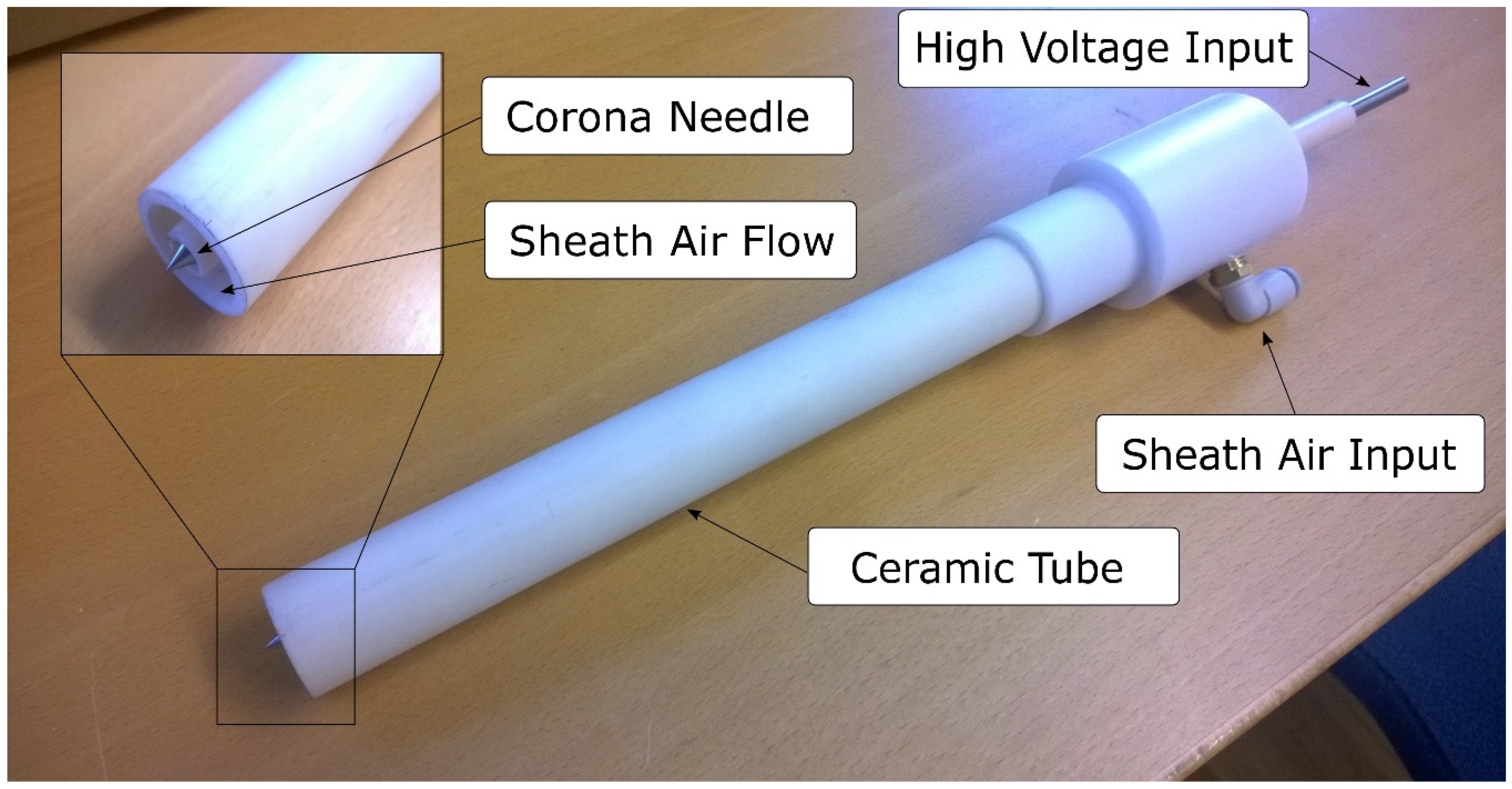
2.1. Shielded Corona Charger

The principles of the SCC have been demonstrated in a previous study [23]. Herein, new designs of the SCC and the SCC chamber were used. The SCC installation chamber design was altered to improve particle charging. The new chamber consists of a round metal tube (diameter 150 mm) to form a uniform electric field inside the chamber. This is better than the previous design, wherein the SCC is installed in a rectangular ceramic flue gas channel, which could potentially cause a problem of back corona [27] due to charge accumulation on top of the thermal insulation. In this case, the charge may fail to transfer into the collection electrode, which is the outer surface of the chamber in our experimental setup.
The new design of the SCC consisted of only one corona needle at the end point of a ceramic tube (Figure 1). Inside the ceramic tube was a high-voltage metallic rod with a sheath air channel surrounding the rod. The end point of this rod was sharpened to form a corona needle. The idea behind this design was to keep the corona discharge close to the preferred particle collection system (a CHX or cyclone), so that fewer particles were deposited before the desired collection stage. We estimated that only one corona needle would produce enough ions to charge the particles in the flue gas. Further, a single needle is easier to keep clean than multiple needles, and it requires a smaller amount of sheath air. In addition, this new design proved to be easier to maintain because the gap between the corona needle and ceramic shell was larger, in order to prevent electric breakdowns through the contaminated surface of the ceramic tube. Based on this new design, we developed two versions, each with a different-length ceramic tube and metal rod. The short version was primarily used in the experiments at flue gas temperature ranges of 300–400 and 400–500 °C (Figure 2A). The lower temperature range was achieved by removing the thermal insulation from around the SCC chamber for placement A. When the desired corona needle placement was deep inside the horizontal duct of the combustion reactor to achieve higher temperatures, the long version of the SCC became necessary. The long version was installed from the other end of the of the combustion reactor by inserting it half-way (Figure 2C), so as to have the corona needle on top of the flames. By inserting the long version by its full length (Figure 2B), the temperature around the corona needle was approximately half-way between placements A and C.
The SCC was operated by adjusting the voltage with a high-voltage power supply (HVPS, ION BLAST OY, 150 kV) and applying sheath air around the corona needle. We determined the maximum operating voltage by increasing the voltage until the corona current became unstable. Then, we decreased the voltage to 0.5–1 kV below this maximum. The HVPS also has an automatic regulation and adjustable current limit, which we set to 2.5 mA. The maximum voltage level decreased during operation, which led to the HVPS having an “overcurrent” status as the current limit was reached. In this case, the HVPS was reset, and the maximum operating voltage was sought again. Sheath air flow levels were between 20 dm3/min and 60 dm3/min, which are the minimum and maximum reasonable flow levels for the dimensions of the new SCC design, respectively.

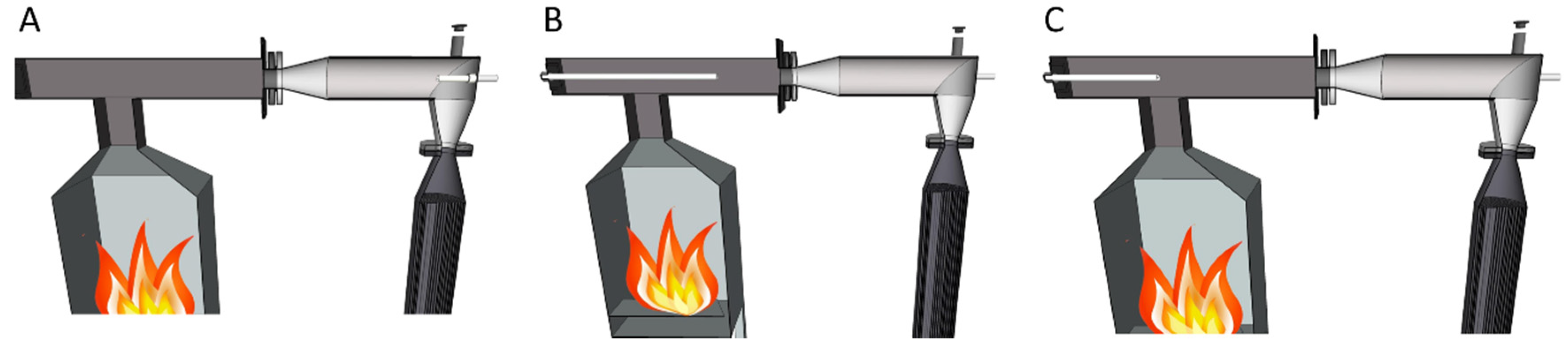
2.2. Experimental Setup

The measurements can be divided into four different campaigns (Table 1): Campaign A includes results from a previous study [23], wherein the old version of SCC in a conventional firetube heat exchanger setup is used, referred to as a reference boiler (REF). Particulate mass reduction in REF is relatively small [15], and in this work the emissions after REF are considered as the reference value, i.e., no particulate reduction efficiency is calculated for REF. In campaign B, the new SCC–CHX setup was tested at different positions, temperatures, and voltages to determine the optimal settings for reduction efficiency. The results were compared to the results from the previous study [23]. In campaign C a series of “long-term” measurements, consisting of one full day (8–12 h), including the startup phase of the reactor, were performed with the optimal settings of the SCC. The objective for this campaign was to test the SCC during the high emissions of the startup phase and stress the SCC under long-lasting contaminating circumstances, which led to problematic soot deposit formation on the SCC tubes. Finally, in campaign D, the CHX was replaced by a cyclone. In this campaign the objective was to examine the usability of SCC as a retrofitting solution in boilers equipped with cyclones. Further, the experiments of campaign D give information on the effects of collector surface area and residence time on SCC efficiency. All experiments were repeated three times, except in campaign C where the long-term measurement under the higher temperature range was taken only once, for both SCC on and SCC off cases. Further, the “SCC–CHX new” experiments were repeated 1–3 times and the amounts of replicates are indicated in Table 2 and Table 3. Each individual experiment replicate includes a substantial amount of online measurement data during stable experimental conditions.
Separate experiments regarding the temperature required for the oxidation of soot deposits were performed with SCC tubes that were coated by soot in campaign C’s lower temperature experiments. In these experiments, the soot deposited on the SCC tubes was heated as a function of temperature in a tube furnace in the presence of a simulated flue gas composition (10% O2, 10% H2O, and 80% N2). The oxidation of the soot deposits was measured as evolving CO2 and CO gases using a Fourier transform infrared spectroscopy (FTIR) gas analyzer (Gasmet DX4000, Vantaa, Finland).
The combustion device used herein was a reciprocating grate burner with a nominal fuel power of 40 kW. Details regarding the combustion reactor are presented in an earlier publication [28]. The burner was designed for miscellaneous solid fuels, and in this experiment, mixed wood chips with an average size of 30 × 30 mm from both hardwood and softwood were used as fuel. The moisture content of the fuel was approximately 30% (weight%). Combustion air in the burner was divided into primary air fed through the grate and secondary air fed above the fuel bed. Combustion air volume flows were measured with hot-wire sensors and were adjusted with control valves. The modular combustion reactor contains a burner and combustion chamber, in addition to a separate heat exchanger section (Figure 3). In measurement campaign A, reference measurements were taken using the reference boiler, while in campaigns B and C, this was replaced with the CHX. In campaigns A and B (Table 1), the combustion reactor was preheated prior to measurements to stabilize the temperatures. Meanwhile, in campaigns C and D, no preheating was done, and the SCC was placed in the flue gas channel before ignition in order to achieve faster fouling of the SCC tube.
Pressure in the combustion chamber was logic-controlled by a flue gas fan and it was set to 10 Pa under atmospheric pressure. The mass flow of fuel was adjusted to between 2.2 and 2.6 kg/h. Primary and secondary combustion air volume flows were set to 30 dm3/min and 180 dm3/min, respectively. Temperatures from water and flue gas were measured with K-type thermocouples. Flue gas temperatures were measured before and after CHX and from the aerosol sampling point (Figure 3). Water temperature for the reference boiler was kept at 60 °C, while the temperatures for the CHX were 35 °C and 30 °C at the outlet and inlet, respectively. The volume flow of the water in the CHX was kept to between 12 dm3/min and 15 dm3/min. The flue gas volume flow and air-to-fuel ratio were approximately 0.5 Nm3/min and 2.8, respectively. The emission conversion factor for the approximate conversion of emission flue gas concentration (mg/m3 at 10% O2) to an emission factor (mg/MJ) was 0.49 m3/MJ, according to standard SFS5624.
In campaign D, a stainless-steel cyclone separator was installed in the combustion reactor setup downstream of the SCC. The measurement setup was similar to that in the SCC–CHX measurements, but the cyclone replaced the CHX after the SCC chamber (Figure 4). The flue gas channel after the cyclone was not thermally insulated to cool the flue gas to be suitable for measurement devices. The cyclone was 500 mm long with an 80 mm diameter cylinder part. The particle cut size and flue gas residence time in the cyclone were calculated according to Shepherd and Lapple [29], resulting in an approximately 4 μm cut size at a flow rate of 0.5 Nm3/min at 400 °C and a 0.12 s residence time.

2.3. Flue Gas Composition and Emission Measurements and Calculation

Gaseous emission components were measured using Fourier transform infrared spectroscopy (FTIR DX-4000, Gasmet, Vantaa, Finland) from the undiluted flue gas through a heated sampling probe and sampling line (180 °C). Aerosol sampling was performed with a heated in-stack sampling probe (250 °C). The sampling setup included a pre-cut cyclone to remove coarse particles from the sample (cut-off diameter 10 µm) and a two-stage dilution system. Primary dilution was performed with a porous tube diluter (PRD) and secondary dilution with ejector diluter (ED). Particulate emissions and their size distributions were measured online from diluted flue gas with an electrical low-pressure impactor (ELPI, Dekati, Kangasala, Finland) and scanning mobility particle sizer (SMPS, TSI Inc., Minneapolis, MN, USA) (CPC model 3776, DMA model 3081, and model 3085). Further, ELPI results were used to determine emissions of fine particle mass (PM0.9) and number (PN0.9) below the particle aerodynamic diameter of 0.9 µm. Similarly, SMPS results were used to determine fine particle mass (PM0.7) and number (PN0.7) below the particle mobility diameter of 0.7 µm. This way several different metrics for fine particle emissions could be derived.
Offline samples of PM1 fractions were collected on PTFE filters for gravimetric, and quartz fiber filters for carbon, analysis [7]. Filter samples were also taken from the total suspended particles (TSP) fraction using isokinetic sampling of undiluted flue gas in a heated quartz fiber filter. Additionally, particulate emissions were measured periodically from the flue gas before the CHX with ELPI. For this sampling point, aerosol dilution was achieved using PRD.
The measured particle concentrations were multiplied by the dilution ratios used in the sampling system. The dilution ratios for aerosol sampling were calculated based on the CO2 concentrations in raw flue gas and a diluted sample with the following equation:
D R = C O 2 , F G C O 2 , B G C O 2 , D C O 2 , B G
where DR is dilution ratio, CO2,FG is the concentration in flue gas, CO2,BG is the concentration in diluted air and CO2,D is the concentration in the sample. All results were normalized to 10% flue gas oxygen concentration as follows:
c n o r m = c m · 20.9 E r e f 20.9 E m
where Cnorm is the emission concentration at 10% of oxygen, Cm is the measured emission concentration, Eref is the reference oxygen concentration (here 10%) and Em is the measured oxygen concentration. Additionally, all results have been corrected for moisture and temperature (dry, 0 °C). A factor for converting the emissions to the mg/MJ1 unit was calculated according to SFS5624 standard [30].

3. Results and Discussion

In this section, we first present a comparison of the different measurement systems in determining the particle mass reduction efficiencies. Second, we define how the SCC’s operating conditions affect its performance, the resultant PM filtration efficiency and particle size distributions upstream of the heat exchanger, and discuss the implications of these results regarding SCC-based filtration systems in biomass-fired boilers. Third, we show how SCC usage in a boiler equipped with CHX affects deposition in the heat exchanger, and evaluate the resulting particle size distributions downstream of the heat exchanger. Next, the effects of the SCC on PM emissions in different boiler setups are presented, including combinations of the SCC with (1) CHX, (2) a conventional firetube heat exchanger, and (3) a cyclone, providing insight regarding the usability and retrofitting possibilities of the method in different boiler settings. Finally, we detail how the SCC tube’s fouling under long-term operation affects its performance at different flue gas temperature ranges, by inducing accelerated fouling under sooty conditions in the boiler.
In total, three measurement campaigns were conducted as summarized in Table 1. In addition, we compared our results with those from a previous study [23]. In general, the combustion conditions in campaigns A–D represent normal automatic boiler operations with respect to CO, THC, and PM emissions [31,32]. The PM consisted mostly of ash species and elemental carbon (EC), while organic carbon (OC) contents were low, with the exception of campaigns C and D, wherein a substantial fraction of the PM consisted of carbonaceous species as a result of including the unstable combustion phases, such as the combustion reactor startup phase, in the measurements. In the following sections, the results of particle concentrations and filtration efficiencies are based on online measurements using SMPS and ELPI, and offline measurements using filter sample collections. Based on these measurements, the fine particle mass reduction efficiencies could be determined via three different measurement principles. In general, SMPS showed lower concentrations of fine particle mass (measured as PM0.7) than other measurements, and a lower mean diameter of particle sizes than the ELPI results (Figure 5B). The larger aerodynamic particle size found using ELPI in comparison to the mobility diameter measured by SMPS indicates an effective density greater, on average, than 1 g/cm3 for the particles. However, although different measurement principles resulted in different mass concentration values, the reduction efficiencies were in relatively good agreement (Figure 5A).

3.1. Effects of Operating Conditions on PM Reduction Efficiency

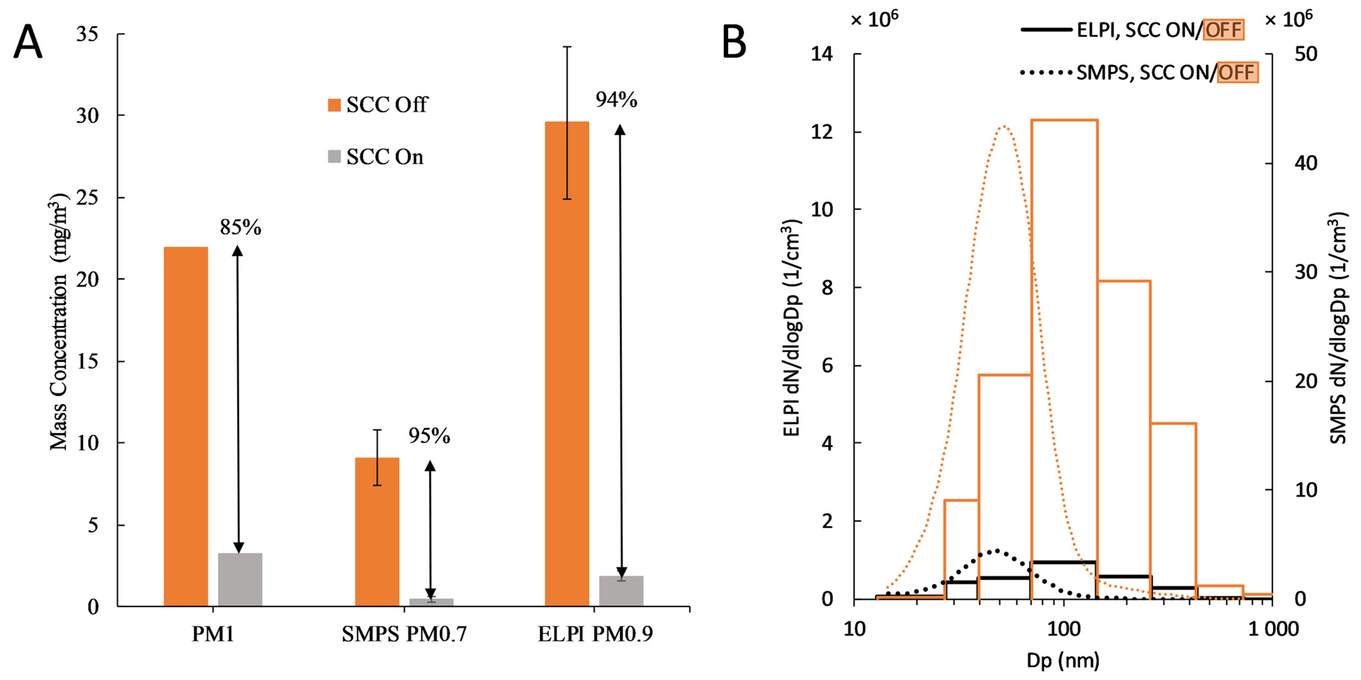
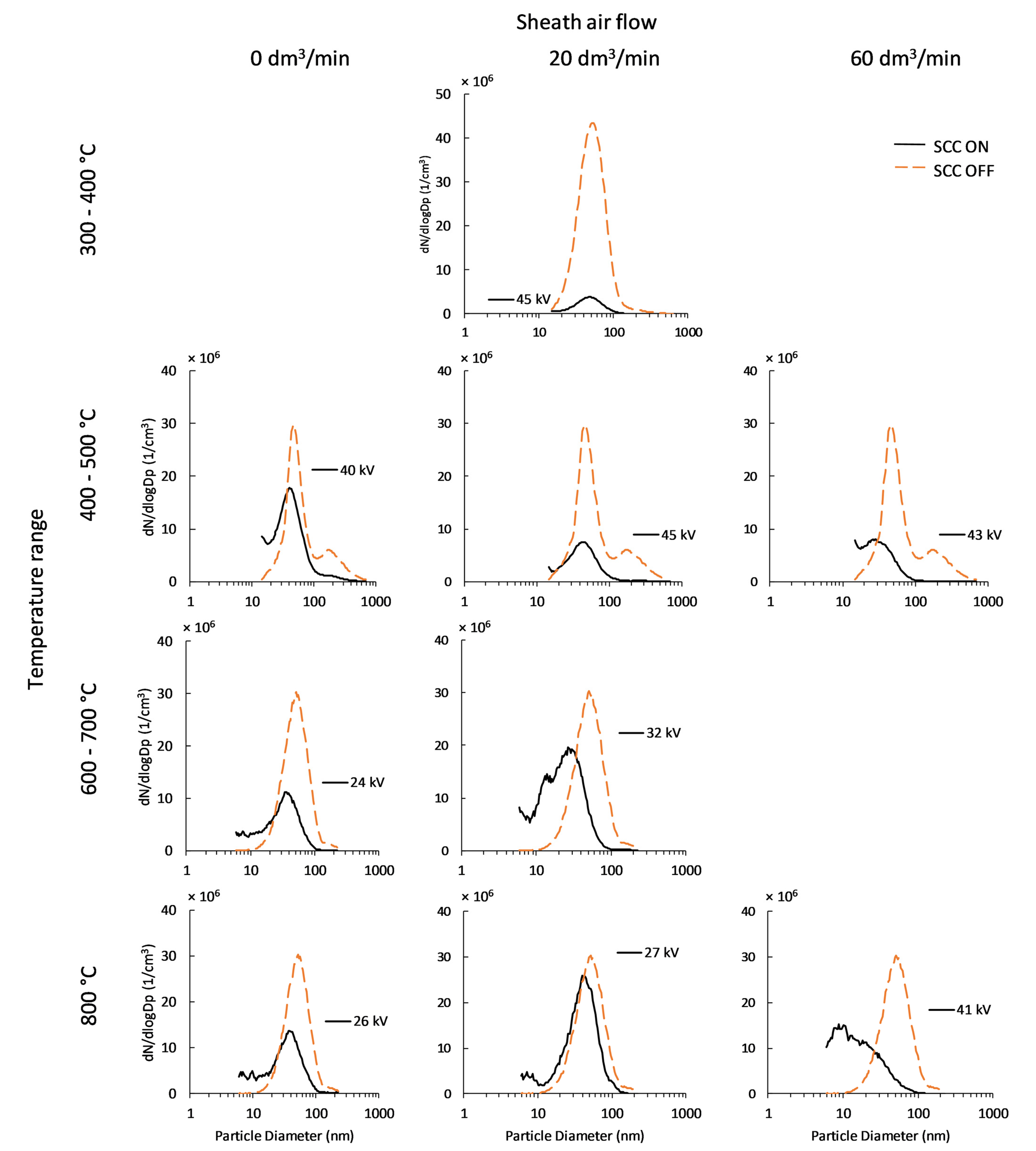
3.1.1. Effect of the SCC on Particle Concentrations and Size Distributions Upstream of the CHX

In exhaust filtration applications, wherein the SCC is installed prior to the heat exchanger, the temperatures vary depending on several factors, including the combustion chamber design, boiler load, air-to-fuel ratio, and fuel calorific value. Even within the same boiler setup using homogeneous fuel, temperatures may vary as a result of changes in heat demand leading to intermittent operation. Therefore, it is essential to know how flue gas temperature affects the SCC reduction efficiency. In addition, we found that the demand for sheath air flow to achieve a stable corona varies depending on the temperature. Table 2 lists the achieved fine PM and particle number emission reduction efficiencies of the SCC in the CHX boiler setup as a function of operation temperature.
Four different setups were used to compare the SCC performance at different temperatures. A 300–400 °C regime was achieved using the SCC chamber without thermal insulation. This temperature is below the black carbon oxidation temperature, which is approximately 470 °C according to Nevalainen et al. [33]. Therefore, high amounts of black carbon were deposited on the SCC’s dielectric cover, forming an electrically conductive layer of soot. A 400–500 °C regime was reached by adding thermal insulation around the SCC chamber. Here, the temperature was evidently high enough that some of the soot was oxidized. Next, a 600–700 °C regime was attained by installing the SCC inside the combustion chamber, in a region where already a substantial part of the heat was recovered by the combustion chamber walls. The highest temperature of approximately 800 °C was achieved by installing the SCC inside the burner chamber on top of the flames.
The surrounding temperature had a certain effect on the SCC’s maximum stable voltage, as summarized in Table 2. In the 400–500 °C temperature regime, maximum voltages of 40 kV and 45 kV were reached with sheath air off and on, respectively. However, without sheath air, the corona became unstable in a matter of minutes and the HVPS started adjusting the voltage, which resulted in a lower reduction efficiency (50% of PM0.9 mass). A sheath air flow of 20 dm3/min was sufficient to keep the corona stable, maintaining a reduction efficiency of 76%. Note that a sheath air flow of 60 dm3/min had no noticeable effect on the results. In the 600–700 °C temperature regime, the corona discharge was unstable over voltages of 24 kV and 32 kV with sheath air off and on, respectively. The corresponding PM0.9 reduction efficiencies were 57% and 41%, respectively. Here, the particle number concentration doubled (negative reduction efficiency) when the sheath air was on. Similar results were obtained at the highest temperature of 800 °C, wherein a relatively low stable corona voltage was recorded, with both no and 20 dm3/min sheath air. Nevertheless, the PM0.9 reduction efficiency at this high temperature was approximately 50%. However, a much lower or even negative reduction efficiency was measured for particle number concentration PN0.9. The negative reduction efficiency was caused by new particle formation, as is explained later in this section when we discuss the particle size distributions. A high sheath air flow of 60 dm3/min stabilized the corona up to 41 kV, thereby achieving high reduction efficiencies of 87% and 39% for PM0.9 and PN0.9, respectively.
The surrounding temperature presumably affected the corona discharge by two ways: fouling and ion mobility. A lower temperature caused more fouling on top of the SCC, creating an electrical short circuit risk, thereby preventing the use of high voltage. This could decrease the reduction efficiency or even completely prevent the formation of stable corona. At higher temperatures, fouling was not a problem. However, relatively low stable corona voltages were achieved as a result of increased ion mobility [34], thermal ionization [35], and the presence of naturally charged particles [36,37]. At high temperatures, highly mobile ions and naturally charged particles may create conducting channels for electric arcs. Thus, the difference between the corona onset voltage and the corona breakthrough voltage becomes narrow, which may prevent the formation of a stable corona discharge.
Both fouling and ion mobility could be controlled by applying sheath air near the corona needle tip. Sheath air flow prevented the flue gas particles from entering the dielectric cover, and thus, no electrically conductive layer was formed close to the corona needle tip. A high sheath air flow also decreased the temperature at the corona discharge zone, lowering the ion mobility locally, thereby preventing arcing. However, high sheath air flow is not advantageous in boilers as it negatively affects the thermal efficiency of the boiler. Therefore, the lowest possible sheath air flow rate is preferred.
The differences between the PN0.9 and PM0.9 reduction efficiencies are visible in the particle size distributions (Figure 6). In the 400–500 °C regime, the particle number concentrations decreased almost size-independently when the SCC was on. Meanwhile, at higher temperatures, there was a large increase in the number of smaller particles, which explains the negative particle number reduction efficiencies. This increase, due to the existence of very small nanoparticles in the emissions, indicates that a nucleation process occurs in the flue gas. Hypothetically, this is possible because the SCC removes the primary particles that act as seeds in a temperature regime where alkali metal vapors normally condense in the flue gas [38]. When the majority of these seeds are gone, condensable vapors, such as alkali metal chlorides, form new particles through homogeneous nucleation. Further, the addition of sheath air near the corona needle rapidly decreases gas temperatures, which may form zones that are favorable for vapor nucleation, similarly to what was observed in the study of Sippula et al. [39]. Note that in the high-temperature setup (Figure 2B,C), the corona needle is faced downstream of the flue gas. Therefore, the electric field generated by the charger conductor rail could not have trapped these nanoparticles, unlike with the other setups. Overall, the results indicate that the optimal operating conditions occurred in the lowest temperature regime, wherein relatively high reduction efficiencies were achieved at low sheath air flow rates. Good efficiency was also attained at a very high temperature when using high sheath flow. Further, a high PM reduction (49%) was achieved at a high temperature without sheath air when the corona was not stable. This could be due to the presence of naturally charged particles, which are collected in the electric field, at high temperatures, but this finding requires validation that is outside the scope of this study. Nevertheless, these results imply that even though high temperatures may occur upstream of the heat exchangers during boiler operation as a result of high load conditions, the SCC can be used to remove particles by either increasing the sheath air flow rate to achieve sufficient cooling or using the electric field during high-temperature operation phases.

3.1.2. Effect of SCC on Particle Concentrations, Size Distributions Downstream of the CHX, and Overall Filtration Efficiency of the SCC–CHX Setup

Particle number size distributions were continuously measured using SMPS under different SCC operating conditions to determine the effects of the SCC on the overall particle reduction in the SCC–CHX system. By comparing the SCC-induced filtration efficiencies upstream (Table 2) and downstream (Table 3) of the CHX, we found that a further significant reduction in particles occurs in the CHX. These measurements showed an overall increase in particle mass reduction efficiencies, reaching as high as 97% for PM0.7 under the optimal settings. The particle number reduction efficiency under the optimal settings slightly decreased when measured after the CHX, resulting in 76% for PN0.7. At high temperatures, the particle number reduction efficiency showed an overall increase, compared to the low and negative efficiencies before the CHX. This increase in reduction efficiency can be explained via several factors. First, the heat exchanger provides residence time and surface area for further deposition of the electrically charged particles. Second, particle size-independent thermophoretic losses that are caused by the temperature gradient between the flue gas and heat exchanger walls, and diffusiophoretic losses due to water vapor condensation, lead to approximately 40% of the PM losses in the CHX [23]. Finally, Brownian diffusion affects very fine nano-sized particles. By comparing particle number size distributions and reduction efficiencies by number concentration before and after the CHX (Figure 6 and Figure 7, Table 2 and Table 3), it is made clear that there are less very small particles after the CHX, which is due to either electrical forces or Brownian diffusion.
The particle charge distributions measured with the ELPI (Figure 8A) indicated that the amounts of charge-decrease in the CHX system were as expected. Calculating the number of charges per particle size (Figure 8B) revealed a 50% decrease in particle charge in the CHX. For particles below 100 nm, this decrease was 80–99%, indicating that the CHX ultrafine particles with higher than average charge rates are more easily deposited in the heat exchanger tubes. The observed particle charge distribution measured directly after the SCC is typical of a diffusion charger [22], with the exception of the losses of ultrafine particles with multiple charges, in the measurement setup used in this experiment (Figure 8B).
In total, the filtration efficiency of the SCC–CHX setup was similar to that of a traditional ESP system, with the advantage that no separate particle collection and collection plate cleaning system are necessary in the boiler setup.

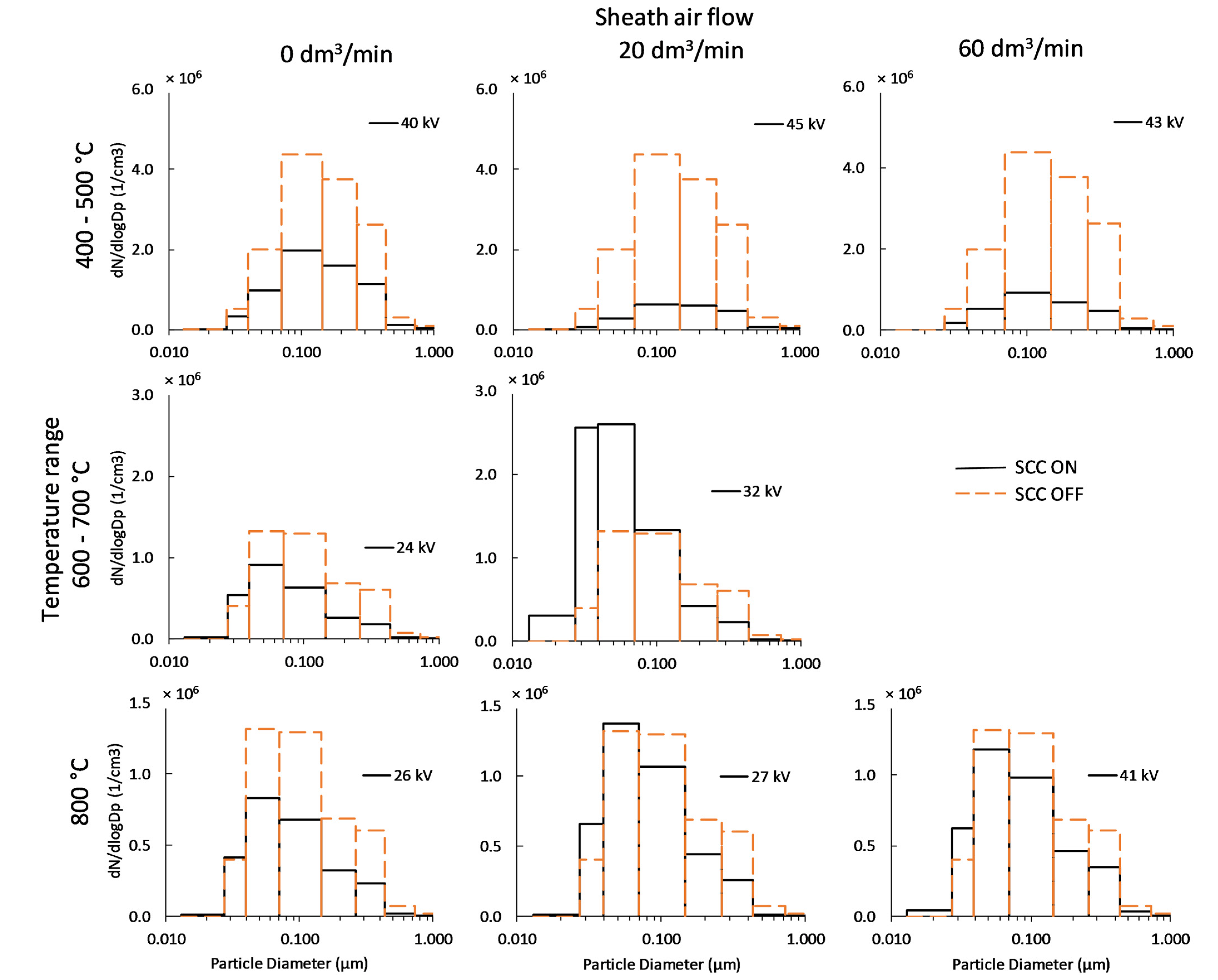
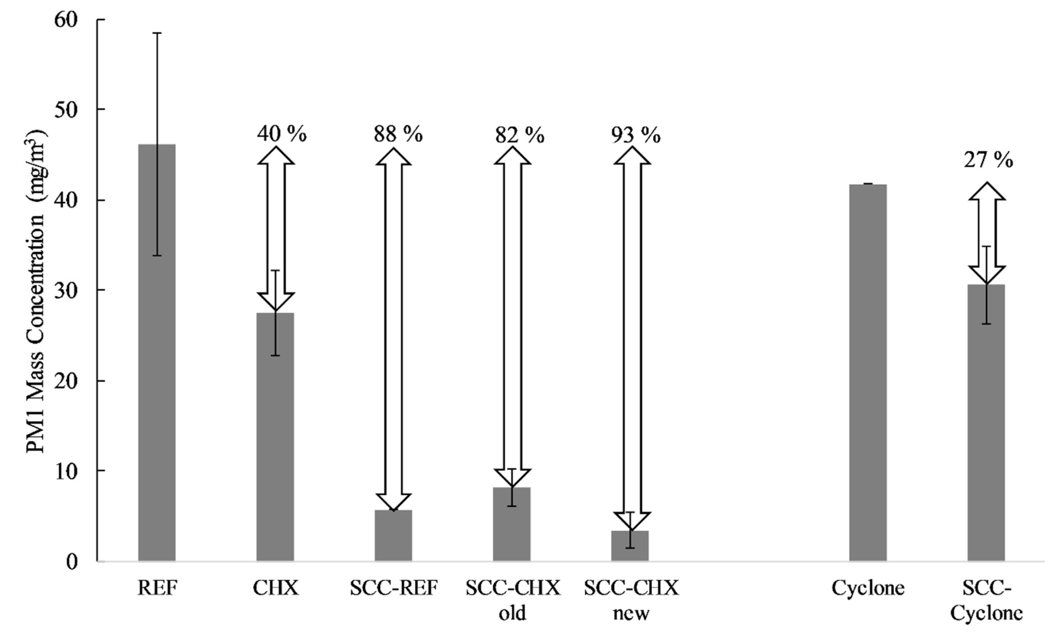
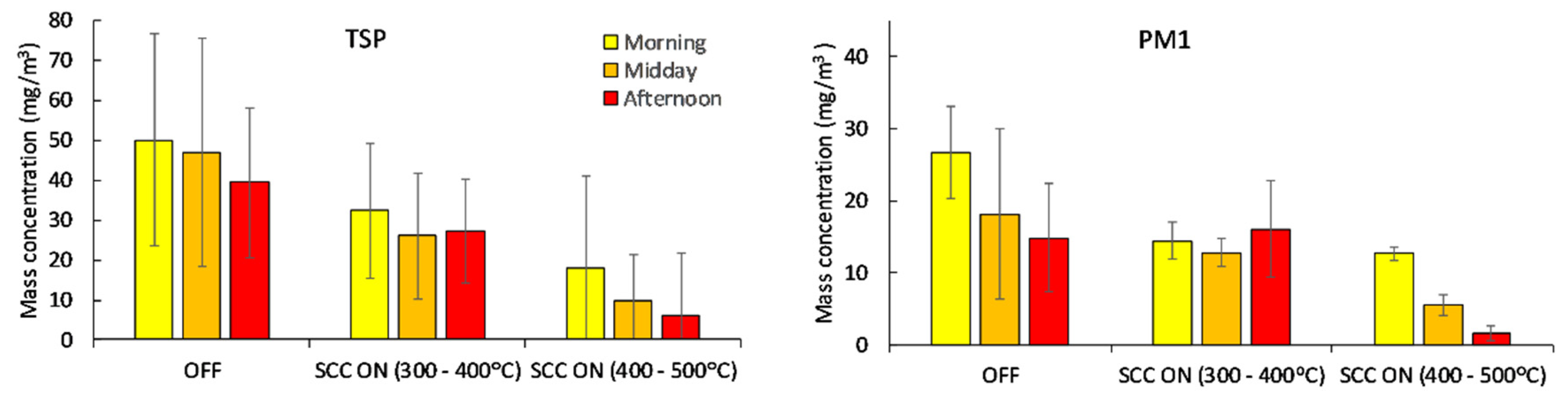
3.2. Effects of SCC on Particle Filtration Efficiencies in Different Boiler Setups

To further study the applicability of SCC in reducing particle emissions in different boiler setups, the SCC was also studied upstream of a cyclone. In addition, experiments from a previous study using the SCC upstream of a conventional firetube heat exchanger are included in the comparison. The SCC operating temperature was 400–500 °C, which was observed to be the most favorable temperature in terms of PM reduction (Table 3). Overall, this comparison helps us to understand the retrofitting possibilities of SCC in existing boilers.
The new SCC system, which is located in the optimized charging chamber, resulted in a somewhat higher overall PM1 reduction efficiency in combination with the CHX (89%) when compared to the previous system (82%), which was located in the ceramic flue gas channel (Figure 9). Interestingly, the SCC system upstream of the conventional firetube boiler was slightly more efficient (88%) than the system combined with the CHX, although this difference is not significant, especially when considering measurement uncertainties and result deviations. Nevertheless, this slight difference might be due to the considerably higher residence time in the firetube heat exchanger (>1.5 s) as compared to that of the CHX (0.5–0.6 s), although the CHX has a higher particle thermophoretic deposition than the firetube heat exchanger [15]. Residence time is essential for the electrical deposition of charged particles in the absence of an external electrical field, because in these cases the particle drifting velocities can be low. On the other hand, the benefits of the CHX are its compact size and its ability to self-clean via flue gas water condensation, which prevents fouling of the heat exchanger tubes. The results of the SCC–CHX system also indicate that the SCC system could be placed upstream of conventional flue gas scrubbers (which typically have long flue gas residence times and large surface areas), where moisture caused by flue gas condensation and scrubbing water feeding provide a cleaning solution.
The effect of the SCC upstream of the cyclone was less pronounced, removing approximately 27% of PM1 (Figure 9). This lower PM1 reduction, as compared with the SCC operation upstream of the heat exchangers, could be the result of various factors. First, the flue gas residence time in the cyclone is only 0.12 s. Second, highly turbulent flow conditions occur in the cyclone, which weakens the particle drift caused by the space charge force to the surfaces, while the flow conditions in the CHX are laminar. Despite the moderate PM reduction efficiency of the SCC–cyclone setup, the SCC could still be useful if operated upstream of the cyclones in small- to medium-sized boilers that have problems fulfilling the legislative emission limits, but do not require very high particle emission reduction improvements. When higher PM reduction efficiencies are required, either traditional particle filtration systems, such as ESPs or fabric filters, must be considered, or, if possible, the SCC system can be used upstream of the heat exchangers. However, as we previously mentioned, the SCC’s operating conditions, such as temperature, affect its efficiency, and the applicability of the SCC system in existing boiler designs is case-specific.
Overall, retrofitting the SCC to be before heat exchangers, flue gas scrubbers, or cyclones could provide a low-cost solution for small heating plants that need to be upgraded to meet tightening emission regulations. Currently, in Finland, this is especially an issue as many existing 1–5 MW biomass boilers regulated by the MCP directive are not equipped with efficient particulate filters [7]. Thus, their PM emissions often exceed the MCP limit values (EU Regulation 2015/2193). For smaller boiler sizes in the range of 0–1000 kW, emissions are regulated by the Ecodesign directive. For example, for automatically fired 0–500 kW boilers, the PM emission limit is 40 mg/m3. This is in the range of the typical emissions of automatic pellet and wood chip boilers without particle filtration systems operating under stable combustion conditions with good-quality fuels [40,41]. This range is also just slightly below the PM emission range of the grate combustion setup in this study (46 mg/m3 with the REF boiler). In these scenarios, using an SCC upstream of the heat exchangers or cyclone could be an economically attractive solution that ensures that the boilers meet the emission limits when operating with lower-quality wood fuels, or if emission limits are tightened in the future.

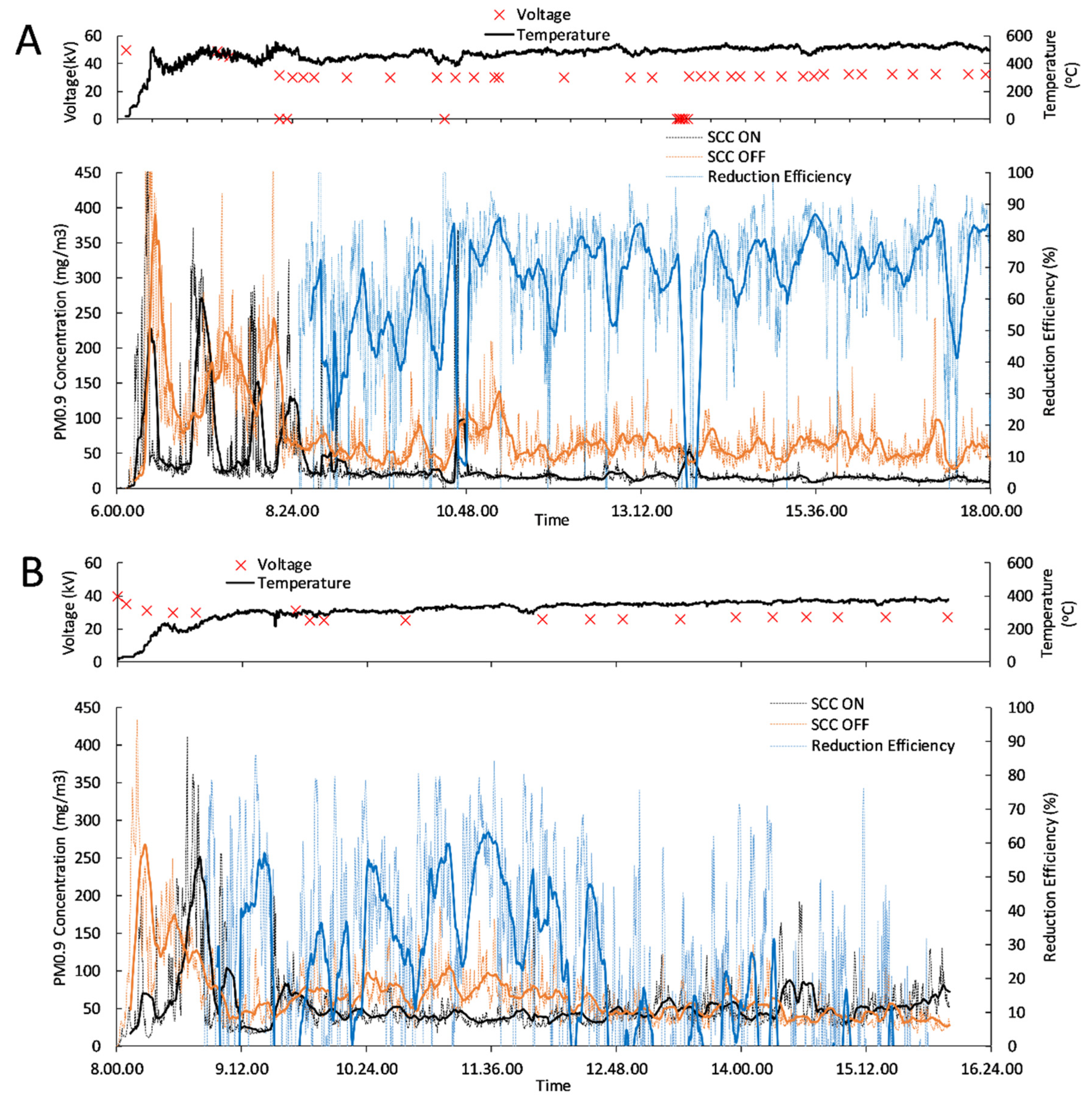
3.3. Long-Term SCC Performance under Sooty Conditions

In real-world usage, boilers operate under highly varying conditions for long periods, including phases with relatively high PM emissions, such as the startup phase, low-load conditions, and intermittent operation. These conditions can lead to momentary high concentrations of soot particles and organics that may cause fouling of the SCC tube. To understand how SCC performs under these conditions, experiments wherein the PM and soot concentrations were increased by creating incomplete combustion conditions were conducted. Further, the SCC was operated in two different temperature-stabilized situations: 300–400 °C and 400–500 °C.
The start of this experiment was characterized by high PM emissions and fluctuating emission concentrations, which is typical for the ignition and heating phases of a combustion boiler system. During these phases, the calculated reduction efficiency fluctuates significantly. When the combustion conditions stabilized, the reduction efficiency converged to approximately 75% when operated at 400–500 °C (Figure 10A), and there were no signs of decreased filtration efficiency due to SCC fouling. At an operating temperature range of 300–400 °C (Figure 10B), the highest reduction efficiency achieved was approximately 60%. Here, the voltage had to be reduced to avoid electrical breakthrough, causing the PM reduction efficiency to decrease after reaching the maximum, apparently due to the fouling of the SCC tube. The long-term performance of the SCC was evaluated by collecting filter samples in the morning, midday, and afternoon of the measurement day (Figure 11), which correspond to ignition, intermittent, and stable combustion conditions, respectively, as the combustion reactor warms up to its stable temperature. The respective PM concentrations were the highest for the ignition phase and lowest for the stable combustion conditions. In the morning, the filter samples showed increased concentrations of particle mass, but the SCC was able to reduce it greatly. In the afternoon, the SCC in the 300–400 °C setup did not noticeably reduce the PM concentration, whereas in the 400–500 °C setup, the SCC decreased the TSP and PM1 concentrations, on average, 84% and 89%, respectively. Thus, a higher temperature range is required for the oxidation of soot deposits from the SCC tube in order to maintain the constant operation of SCC at high soot loads. At lower temperatures, the SCC requires further optimization to lower the leakage current.
Further experiments regarding the temperature required for soot oxidation were performed separately with SCC tubes that were coated by soot in the lower temperature experiments. The results indicate that at least 430 °C is required for the oxidation of the wood combustion soot (Figure 12), which agrees well with the observed differences in soot accumulation during the long-term grate reactor experiments. To improve the soot oxidation of the SCC tubes, the tubes could be coated with a soot oxidation catalyst. For example, aluminum oxide-supported silver catalysts have displayed reasonably low temperature soot oxidation performance, and could be utilized to clean the tubes at a temperature as low as 310 °C [33,42].

4. Conclusions

The SCC operating temperature considerably affected the PM and PN reduction efficiencies. The highest PM reduction efficiency was achieved at 400–500 °C, while lower temperatures led to a higher PN reduction efficiency, but impaired the SCC’s long-term operation as a result of soot deposits on the SCC tube. Using the proposed setup, these soot deposits were found to be problematic as they form an electrically conductive layer that leads to electric current leakage and possible breakthroughs. Thus, a temperature range of 400–500 °C was required because at this range, the soot deposits are continuously oxidized. At lower temperatures, the SCC design would need further development to avoid current leakage. Meanwhile, SCC operation at higher temperatures led to a decrease in the PM and PN reduction efficiencies due to unstable corona discharge and the formation of new particles, which is caused by the nucleation of condensable vapors, wherein the SCC removes seed particles from the flue gas, thereby promoting new particle formation. However, relatively high PM reduction efficiencies were achieved at high temperatures when using high sheath air flow rates in the SCC.
SCC technology is beneficial as it can be utilized upstream of many different boiler components that contain surface areas for particle collection, such as heat exchangers, cyclones, or wet scrubbers. Thus, the SCC technology offers options for existing boiler plants to decrease their particle emissions by retrofitting without the need for extensive investments and additional space, which are necessary for traditional EPSs and fabric filters. Further, the SCC offers a cost-efficient solution for manufacturers to meet the emission regulations of small-scale boilers. The system can be scaled up to larger boilers by increasing the number of corona chargers, as long as there is sufficient residence time and surface area available for particle deposition.
The SCC was found to yield a moderate (27%) reduction efficiency when operated upstream of a cyclone. As most small-scale biomass boilers above 0.5 MW power are equipped with cyclones, this could be an attractive low-cost solution for improving emission control in existing boiler plants. When the SCC was operated either upstream of a conventional firetube heat exchanger or a CHX, there was a significant PM reduction (80–90%) as a result of the higher residence times than in a cyclone. Thus, SCC installed in combination with a heat exchanger can be an alternative to a traditional ESP in small- to medium-sized boilers. A similar efficiency can be expected when the SCC is utilized with a wet scrubber, which often have a relatively high surface area and residence time, and which are widely used in medium-sized boilers [43,44]. In the scrubbers as well as the CHX, the collected particles are flushed with the condense/scrubber water. Therefore, no additional dust removal systems are required. The online electrical charge measurements taken before and after the CHX further confirmed that the charged particles were efficiently deposited in the heat exchanger tubes.

Author Contributions

Conceptualization, H.S., O.S., A.L. and J.T.; methodology, H.S., A.L., O.S., M.K., M.I., N.K. and J.J.; investigation, H.S., M.K., P.Y.-P., H.K., P.T., N.K. and O.S.; data curation, H.S.; writing—original draft preparation, H.S. and O.S.; writing—review and editing, H.S., A.L., M.K., N.K., O.S., H.K., P.T. and M.I.; visualization, H.S.; supervision, O.S., J.T., J.J. and M.S.; project administration, O.S.; funding acquisition, O.S., J.J. and M.S. All authors have read and agreed to the published version of the manuscript.

Funding

This work was financially supported by the European Regional Development Fund, Fortum heat and power, Savon voima, and Ramboll as part of the Pyreus project (Grant A70994), as well as the doctoral school of the University of Eastern Finland.

Data Availability Statement

Data is contained within the article. Part of the data presented in this study are available with more details in Grigonytė-Lopez Rodriguez et al. [23]. Full data files of this study are available on request from the corresponding author.

Acknowledgments

We thank Mika Räihä from Tassu ESP for technical and material support.

Conflicts of Interest

The authors declare no conflict of interest.

References

  1. Denier Van Der Gon, H.A.C.; Bergström, R.; Fountoukis, C.; Johansson, C.; Pandis, S.N.; Simpson, D.; Visschedijk, A.J.H. Particulate emissions from residential wood combustion in Europe—Revised estimates and an evaluation. Atmos. Chem. Phys. 2015, 15, 6503–6519. [Google Scholar] [CrossRef] [Green Version]
  2. Savolahti, M.; Karvosenoja, N.; Tissari, J.; Kupiainen, K.; Sippula, O.; Jokiniemi, J. Black carbon and fine particle emissions in Finnish residential wood combustion: Emission projections, reduction measures and the impact of combustion practices. Atmos. Env. 2016, 140, 495–505. [Google Scholar] [CrossRef]
  3. Ramanathan, V.; Carmichael, G. Global and regional climate changes due to black carbon. Nat. Geosci. 2008, 1, 221–227. [Google Scholar] [CrossRef]
  4. Villeneuve, J.; Palacios, J.H.; Savoie, P.; Godbout, S. A critical review of emission standards and regulations regarding biomass combustion in small scale units (<3 MW). Bioresour. Technol. 2012, 111, 1–11. [Google Scholar] [CrossRef]
  5. Nussbaumer, T. Combustion and Co-combustion of Biomass: Fundamentals, Technologies, and Primary Measures for Emission Reduction. Energy Fuels 2003, 17, 1510–1521. [Google Scholar] [CrossRef]
  6. Morán, J.C.; Míguez, J.L.; Porteiro, J.; Patiño, D.; Granada, E. Low-quality fuels for small-scale combustion boilers: An experimental study. Energy Fuels 2015, 29, 3064–3081. [Google Scholar] [CrossRef]
  7. Sippula, O.; Hokkinen, J.; Puustinen, H.; Yli-Pirilä, P.; Jokiniemi, J. Particle emissions from small wood-fired district heating units. Energy Fuels 2009, 23, 2974–2982. [Google Scholar] [CrossRef]
  8. Sippula, O.; Huttunen, K.; Hokkinen, J.; Suhonen, H.; Kajolinna, T.; Kortelainen, M.; Karhunen, T.; Jalava, P.; Uski, O.; Yli-Piril, P.; et al. Emissions from a fast-pyrolysis bio-oil fired boiler: Comparison of health-related characteristics of emissions from bio-oil, fossil oil and wood. Environ. Pollut. 2019, 248, 888–897. [Google Scholar] [CrossRef]
  9. Jaworek, A.; Krupa, A.; Czech, T. Modern electrostatic devices and methods for exhaust gas cleaning: A brief review. J. Electrostat. 2007, 65, 133–155. [Google Scholar] [CrossRef]
  10. You, C.; Wang, X.; Liu, R.; Yang, R. Simultaneous effects of electrostatic field and thermophoresis on inhalable particulate matter removal. Powder Technol. 2010, 202, 95–100. [Google Scholar] [CrossRef]
  11. Carroll, J.; Finnan, J. Use of electrostatic precipitators in small-scale biomass furnaces to reduce particulate emissions from a range of feedstocks. Biosyst. Eng. 2017, 163, 94–102. [Google Scholar] [CrossRef]
  12. Erol, H.I.; Turgut, O.; Unal, R. Experimental and numerical study of Stairmand cyclone separators: A comparison of the results of small-scale and large-scale cyclones. Heat Mass Transf. 2019, 55, 2341–2354. [Google Scholar] [CrossRef]
  13. Gröhn, A.; Suonmaa, V.; Auvinen, A.; Lehtinen, K.E.J.; Jokiniemi, J. Reduction of fine particle emissions from wood combustion with optimized condensing heat exchangers. Env. Sci. Technol. 2009, 43, 6269–6274. [Google Scholar] [CrossRef] [PubMed]
  14. Messerer, A.; Niessner, R.; Pöschl, U. Miniature pipe bundle heat exchanger for thermophoretic deposition of ultrafine soot aerosol particles at high flow velocities. Aerosol Sci. Technol. 2004, 38, 456–466. [Google Scholar] [CrossRef]
  15. Grigonyte, J.; Nuutinen, I.; Koponen, T.; Lamberg, H.; Tissari, J.; Jokiniemi, J.; Sippula, O. Evaluation of a heat exchanger designed for efficient fine particle precipitation in small-scale wood combustion. Energy Fuels 2014, 28, 6058–6065. [Google Scholar] [CrossRef]
  16. Bianchini, A.; Pellegrini, M.; Rossi, J.; Saccani, C. Theoretical model and preliminary design of an innovative wet scrubber for the separation of fine particulate matter produced by biomass combustion in small size boilers. Biomass Bioenergy 2018, 116, 60–71. [Google Scholar] [CrossRef]
  17. Brandelet, B.; Pascual, C.; Debal, M.; Rogaume, Y. A cleaner biomass energy production by optimization of the operational range of a fabric filter. J. Clean. Prod. 2020, 253, 119906. [Google Scholar] [CrossRef]
  18. Mirjam, M.; Ingo, H.; Joachim, S.; Dirk, E. Characterization and integration of oxidation catalysts at small-scale biomass combustion furnaces. E3S Web Conf. 2017, 19, 01006. [Google Scholar] [CrossRef] [Green Version]
  19. Bindig, R.; Butt, S.; Hartmann, I.; Matthes, M.; Thiel, C. Application of heterogeneous catalysis in small-scale biomass combustion systems. Catalysts 2012, 2, 223. [Google Scholar] [CrossRef] [Green Version]
  20. Patiño, D.; Crespo, B.; Porteiro, J.; Villaravid, E.; Granada, E. Experimental study of a tubular-type ESP for small-scale biomass boilers: Preliminary results in a diesel engine. Powder Technol. 2016, 288, 164–175. [Google Scholar] [CrossRef]
  21. Migliavacca, G.; Morreale, C.; Hugony, F.; Tombolato, I. Reduction of PM Emissions from Biomass Combustion Appliances: Evaluation of Efficiency of Electrostatic Precipitators. Chem. Eng. Trans. 2014, 37, 25–30. [Google Scholar]
  22. Laitinen, A.; Keskinen, J. Performance of a sonic jet-type charger in high dust load. J. Electrostat. 2016, 83, 1–6. [Google Scholar] [CrossRef] [Green Version]
  23. Grigonytė-Lopez Rodriguez, J.; Suhonen, H.; Laitinen, A.; Tissari, J.; Kortelainen, M.; Tiitta, P.; Lähde, A.; Keskinen, J.; Jokiniemi, J.; Sippula, O. A novel electrical charging condensing heat exchanger for efficient particle emission reduction in small wood boilers. Renew. Energy 2020, 145, 521–529. [Google Scholar] [CrossRef]
  24. Xi, J.; Si, X.; Longest, W. Electrostatic charge effects on pharmaceutical aerosol deposition in human nasal-laryngeal airways. Pharmaceutics 2014, 6, 26–35. [Google Scholar] [CrossRef] [PubMed] [Green Version]
  25. Xiao, G.; Wang, X.; Zhang, J.; Ni, M.; Gao, X.; Cen, K. Characteristics of DC discharge in a wire-cylinder configuration at high ambient temperatures. J. Electrostat. 2014, 72, 13–21. [Google Scholar] [CrossRef]
  26. Yan, P.; Zheng, C.; Zhu, W.; Xu, X.; Gao, X.; Luo, Z.; Ni, M.; Cen, K. An experimental study on the effects of temperature and pressure on negative corona discharge in high-temperature ESPs. Appl. Energy 2016, 164, 28–35. [Google Scholar] [CrossRef]
  27. Ni, M.; Wang, X.; Xiao, G.; Qiu, K.; Yang, G.; Gao, X.; Cen, K. Development of back corona discharge in a wire-cylinder electrostatic precipitator at high temperatures. Powder Technol. 2015, 286, 789–797. [Google Scholar] [CrossRef]
  28. Leskinen, J.; Tissari, J.; Uski, O.; Virén, A.; Torvela, T.; Kaivosoja, T.; Lamberg, H.; Nuutinen, I.; Kettunen, T.; Joutsensaari, J.; et al. Fine particle emissions in three different combustion conditions of a wood chip-fired appliance—Particulate physico-chemical properties and induced cell death. Atmos. Environ. 2014, 86, 129–139. [Google Scholar] [CrossRef]
  29. Shepherd, C.B.; Lapple, C.E. Flow Pattern and Pressure Drop in Cyclone Dust Collectors: Cyclone without Inlet Vane. Ind. Eng. Chem. 1940, 32, 1246–1248. [Google Scholar] [CrossRef]
  30. Reda, A.A.; Czech, H.; Schnelle-Kreis, J.; Sippula, O.; Orasche, J.; Weggler, B.; Abbaszade, G.; Arteaga-Salas, J.M.; Kortelainen, M.; Tissari, J.; et al. Analysis of gas-phase carbonyl compounds in emissions from modern wood combustion appliances: Influence of wood type and combustion appliance. Energy Fuels 2015, 29, 3897–3907. [Google Scholar] [CrossRef]
  31. Schmidl, C.; Luisser, M.; Padouvas, E.; Lasselsberger, L.; Rzaca, M.; Ramirez-Santa Cruz, C.; Handler, M.; Peng, G.; Bauer, H.; Puxbaum, H. Particulate and gaseous emissions from manually and automatically fired small scale combustion systems. Atmos. Environ. 2011, 45, 7443–7454. [Google Scholar] [CrossRef]
  32. Lamberg, H.; Tissari, J.; Jokiniemi, J.; Sippula, O. Fine particle and gaseous emissions from a small-scale boiler fueled by pellets of various raw materials. Energy Fuels 2013, 27, 7044–7053. [Google Scholar] [CrossRef]
  33. Nevalainen, P.; Kinnunen, N.; Suvanto, M. Developmental Study of Soot-Oxidation Catalysts for Fireplaces: The Effect of Binder and Preparation Techniques on Catalyst Texture and Activity. Catalysts 2019, 9, 957. [Google Scholar] [CrossRef] [Green Version]
  34. Czech, T.; Sobczyk, A.T.; Jaworek, A.; Krupa, A. Corona and back discharges in flue-gas simulating mixture. J. Electrostat. 2012, 70, 269–284. [Google Scholar] [CrossRef]
  35. Fialkov, A.B. Investigations on ions in flames. Prog. Energy Combust. Sci. 1997, 23, 399–528. [Google Scholar] [CrossRef]
  36. Kim, S.H.; Woo, K.S.; Liu, B.Y.H.; Zachariah, M.R. Method of measuring charge distribution of nanosized aerosols. J. Colloid. Interface Sci. 2005, 282, 46–57. [Google Scholar] [CrossRef]
  37. Sgro, L.A.; D’Anna, A.; Minutolo, P. Charge Distribution of Incipient Flame-Generated Particles. Aerosol Sci. Technol. 2010, 44, 651–662. [Google Scholar] [CrossRef] [Green Version]
  38. Sippula, O.; Hytönen, K.; Tissari, J.; Raunemaa, T.; Jokiniemi, J. Effect of wood fuel on the emissions from a top-feed pellet stove. Energy Fuels 2007, 21, 1151–1160. [Google Scholar] [CrossRef]
  39. Sippula, O.; Koponen, T.; Jokiniemi, J. Behavior of alkali metal aerosol in a high-temperature porous tube sampling probe. Aerosol Sci. Technol. 2012, 46, 1151–1162. [Google Scholar] [CrossRef] [Green Version]
  40. Lamberg, H.; Nuutinen, K.; Tissari, J.; Ruusunen, J.; Yli-Pirilä, P.; Sippula, O.; Tapanainen, M.; Jalava, P.; Makkonen, U.; Teinilä, K.; et al. Physicochemical characterization of fine particles from small-scale wood combustion. Atmos. Environ. 2011, 45, 7635–7643. [Google Scholar] [CrossRef]
  41. Sippula, O.; Lamberg, H.; Leskinen, J.; Tissari, J.; Jokiniemi, J. Emissions and ash behavior in a 500 kW pellet boiler operated with various blends of woody biomass and peat. Fuel 2017, 202, 144–153. [Google Scholar] [CrossRef]
  42. Shromova, O.A.; Kinnunen, N.M.; Pakkanen, T.A.; Suvanto, M. Promotion effect of water in catalytic fireplace soot oxidation over silver and platinum. RSC Adv. 2017, 7, 46051–46059. [Google Scholar] [CrossRef] [Green Version]
  43. Mussatti, D.; Hemmer, P. Wet Scrubbers for Particulate Matter. In EPA Air Pollution Control Cost Manual; US EPA: Triangle Park, NC, USA, 2002; Chapter 2; Section 6. [Google Scholar]
  44. Laitinen, A.; Hautanen, J.; Keskinen, J. Effect of the space charge precipitation on wet scrubber fine particle removal efficiency. J. Aerosol Sci. 1997, 28, S287–S288. [Google Scholar] [CrossRef]
Figure 1. Design of the shielded corona charger (SCC).
Energies 14 00109 g001
Figure 2. Shielded corona charger (SCC) design and installation locations at (A) 300–400 °C and 400–500 °C when SCC chamber was not insulated and with insulation, respectively, (B) 600–700 °C, and (C) 800 °C.
Energies 14 00109 g002
Figure 3. Experimental setup in the shielded corona charger–condensing heat exchanger (SCC–CHX) measurements.
Energies 14 00109 g003
Figure 4. Experimental setup in the shielded corona charger (SCC) –Cyclone measurements.
Energies 14 00109 g004
Figure 5. (A) Fine particle mass concentrations and (B) particle size distributions downstream of the condensing heat exchanger (CHX) in a short-term measurement using the SCC at a flue gas temperature of 400–500 °C, voltage 45 kV DC, and sheath air 20 dm3/min.
Energies 14 00109 g005
Figure 6. Particle number size distributions measured by an electrical low-pressure impactor (ELPI) upstream of the heat exchangers at different temperatures surrounding the shielded corona charger (SCC) and with different sheath air flow rates.
Energies 14 00109 g006
Figure 7. Particle number size distributions measured by scanning mobility particle sizer (SMPS) in different scenarios of sheath air through the shielded corona charger (SCC) and surrounding temperature at the SCC’s location inside the reactor.
Energies 14 00109 g007
Figure 8. (A) Comparison of particle number and charge size distributions before and after the condensing heat exchanger (CHX) with particle charging on and off and (B) single particle charge distribution.
Energies 14 00109 g008
Figure 9. Reduction efficiencies of fine particle (PM1) mass of different setups, at shielded corona charger (SCC) operating temperatures of 400–500 °C, in comparison to the reference boiler (REF) and condensing heat exchanger (CHX). Note that the results originate from different sets of experiments, and therefore the original particle concentration before the deposition systems is likely to be different.
Energies 14 00109 g009
Figure 10. Shielded corona charger (SCC)-induced reduction efficiency in long-term experiment at temperature ranges of (A) 400–500 °C and (B) 300–400 °C for particulate matter PM0.9 measured by electrical low-pressure impactor (ELPI).
Energies 14 00109 g010
Figure 11. Total suspended particle (TSP) and fine particle (PM1) mass concentrations of flue gases in the long-term experiments with and without usage of a shielded corona charger (SCC) at two different temperature ranges.
Energies 14 00109 g011
Figure 12. CO2 and CO concentrations emitted by the oxidation of soot (deposited on the SCC-tube) as a function of temperature. A gas mixture of 10% O2, 10% H2O and 80% N2 was used in the measurement with a total gas flowrate of 1.2 dm3/min. Soot loading in the measurement was about 8 mg and it was mixed together with alumina powder.
Energies 14 00109 g012
Table 1. Measurement campaigns with different shielded corona charger (SCC) and condensing heat exchanger (CHX) setups. Campaign A includes experiments with a conventional boiler setup and with CHX setup, in which the effects of SCC were studies as described in a previous study [23]. Campaign B, “SCC–CHX new”, consists of a series of measurements where the effects of the SCC operating conditions were studied. Campaign C includes a series of long-term experiments with CHX and CHX–SCC setups. In campaign D the effect of SCC on the particle reduction efficiency of a cyclone was studied. The data are reported as averages with standard deviations, or as a range of typical values if the variance is excessive.
Campaign A: Reference Boiler (REF)Campaign B: Condensing Heat Exchanger (CHX)Campaign C: Long-TermCampaign D: Cyclone
REFShielded Corona Charger (SCC) -REFCHXSCC–CHX OldSCC–CHX New *CHXSCC–CHX NewCycloneSCC–Cyclone
Temperature in the charging section°C616–635 616–635300–400;
400–500;
600–700;
800
300–400;
400–500
400–500
Residence time inside the collection devices>1.50.5–0.60.5–0.60.12
Collection surface aream23.052.282.280.15
SCC voltagekV02002025–45025–34.5028–35
Fine particles (PM1)mg/m346.3 ± 12.35.7 27.6 ± 4.78.2 ± 2.03.5 ± 1.99–342–244231
Organic carbon (OC)mg/m33.3 ± 4.50.1 ± 0.40.4 ± 0.1-0.8 ± 0.60–30–4--
Elemental carbon (EC)mg/m34.1 ± 4.30.6 ± 2.74.7 ± 0.20.4 ± 0.42.7 ± 1.67–383–27--
COmg/m360.4 ± 24.660.0 ± 15.142.7 ± 47.545.6 ± 14.992.8 ± 25.466–1488591–307236303003
* consists of different combustion and SCC charging conditions.
Table 2. Shielded corona charger (SCC)-induced reduction efficiencies of particulate matter (PM) and particle number emissions measured upstream of the heat exchanger at different operating conditions. N is the number of repeated individual experiments. The result of each individual experiment is averaged over a measurement time varying between 10 and 35 min under stable conditions.
Reduction Efficiency by Number Concentration, Electrical Low-Pressure Impactor (ELPI) PN0.9
400–500 °C600–700 °C800 °C
No sheath56 ± 31% @ 40 kV * (N = 2)27% @ 24 kV (N = 1)25% @ 26 kV (N = 1)
20 dm3/min sheath85% @ 45 kV ** (N = 1)−100% @ 32 kV (N = 1)−13% @ 27 kV (N = 1)
60 dm3/min sheath80 ± 8% @ 43 kV (N = 2) 39% @ 41 kV (N = 1)
Reduction Efficiency by Mass Concentration, ELPI PM0.9
400–500 °C600–700 °C800 °C
No sheath50 ± 42% @ 40 kV * (N = 2)57% @ 24 kV (N = 1)49% @ 26 kV (N = 1)
20 dm3/min sheath76% @ 45 kV ** (N = 1)41% @ 32 kV (N = 1)46% @ 27 kV (N = 1)
60 dm3/min sheath78 ± 4% @ 43 kV (N = 2) 87% @ 41 kV (N = 1)
* Unstable corona during the measurement. ** Optimal settings selected for long-term testing.
Table 3. Shielded corona charger (SCC)-induced particulate matter (PM) and particle number reduction efficiencies measured downstream of the condensing heat exchanger (CHX) in different SCC operating conditions. N is the number of repeated individual experiments. The result of each individual experiment is averaged over a measurement time varying between 10 and 40 min under stable conditions.
Reduction Efficiency by Number Concentration, Scanning Mobility Particle Sizer (SMPS) PN0.7
300–400 °C400–500 °C600–700 °C800 °C
No sheath 33 ± 3% @ 40 kV * (N = 2)58% @ 24 kV (N = 1)48% @ 26 kV (N = 1)
20 dm3/min sheath91 ± 1% @ 45 kV (N = 2)76% @ 45 kV ** (N = 1)17% @ 32 kV (N = 1)18% @ 27 kV (N = 1)
60 dm3/min sheath 70 ± 15% @ 43 kV (N = 2) 34% @ 41 kV (N = 1)
Reduction Efficiency by Mass Concentration, SMPS PM0.7
300–400 °C400–500 °C600–700 °C800 °C
No sheath 71 ± 38% @ 40 kV * (N = 2)87% @ 24 kV (N = 1)77% @ 26 kV (N = 1)
20 dm3/min sheath95 ± 1% @ 45 kV (N = 2)97% @ 45 kV ** (N = 1)86% @ 32 kV (N = 1)65% @ 27 kV (N = 1)
60 dm3/min sheath 95 ± 1% @ 43 kV (N = 2) 95% @ 41 kV (N = 1)
* Unstable corona during the measurement. ** Optimal settings selected for long-term testing.
Publisher’s Note: MDPI stays neutral with regard to jurisdictional claims in published maps and institutional affiliations.

