Analysis of the Impact of Stator Inter-Turn Short Circuits on PMSM Drive with Scalar and Vector Control


Department of Electrical Machines, Drives and Measurements, Wroclaw University of Science and Technology, wyb. Wyspianskiego 27, 50-370 Wroclaw, Poland
*
Author to whom correspondence should be addressed.
Energies 2021, 14(1), 153; https://doi.org/10.3390/en14010153
Submission received: 9 December 2020
/
Revised: 23 December 2020
/
Accepted: 25 December 2020
/
Published: 30 December 2020
(This article belongs to the Special Issue Fault Diagnosis in Electric Motors Ⅱ)
Abstract
:Permanent Magnet Synchronous Motor (PMSM) failures are currently widely discussed in the literature, but the impact of these failures on the operation of control systems and the ability to detect selected failures despite the compensating effect of control algorithms being relatively rarely analyzed. The article presents the impact of damage to the stator winding of a PMSM motor on the operation of two frequency control structures, scalar and vector control. The mathematical model of PMSM that takes into account the influence of a different number of shorted turns in the stator winding phase was presented, and its experimental verification was performed. Then, the influence of various degrees of damage to the stator winding on the waveforms of the motor state variables in an open scalar control structure and in a closed field-oriented control structure was analyzed. Based on the analysis of phase currents and rotational speed of the motor as well as the influence of the PMSM motor operating conditions, the basic techniques of extracting the symptoms of stator winding inter-turn short-circuits were analyzed, and the failure indicators were developed, which enable simple diagnostics of the stator winding.
1. Introduction
The popularity of alternating current (AC) electric motors in industry has resulted in increased requirements for their energy efficiency, reliability and operating costs [1]. Permanent magnet synchronous motors (PMSM), which offer high efficiency, wide range of rotational speed control, high torque overload, low rotor inertia, as well as simple structure, fit well with the above-mentioned requirements [2].
Despite the aforementioned advantages of PMSMs, they are prone to damage occurring during their normal operation. This issue is particularly important from the economic point of view of production processes. Unplanned downtimes and failures of the drive systems lead to production losses, in most cases exceeding the cost of purchasing new machines. You can reduce the likelihood of damage to the equipment by applying regular maintenance. Nevertheless, these procedures do not eliminate the causes of faults in electric motors.
Typical failures of PMSM motors include electrical, mechanical, and magnetic failures. Inter-turn short-circuits of the stator winding belonging to electrical defects are the second most common type of damage to electric motors, accounting for about 36% of all failures [3]. Inter-turn short-circuits cause the flow of currents reaching amplitudes with values several times greater than the rated one [4,5]. As a result, the windings heat up at the point of damage, which results in overheating of the insulation and spreading of the failure to successive coils of the stator windings. Short circuits are considered to be one of the most difficult failures to detect, especially in the initial phase of failure. Moreover, their local action is very destructive and usually leads to unplanned drive system downtime and the necessity of its immediate repair or modernization, which often generates high costs.
Obtaining information about the actual technical condition of the drive system is necessary to enable early overhaul of the machine, and to avoid serious failures and long downtimes. Detecting faults and diagnostics of electric motors is an important issue and is constantly being developed by many research centers in the world [5,6,7,8,9].
The currently used methods of diagnosing defects in electrical machines can be divided into three main categories: diagnostics based on mathematical models of the examined objects [10,11,12], diagnostics using measurement signal analysis methods [12,13,14], and diagnostic methods based on artificial intelligence techniques [15,16,17,18].
One of the goals of diagnostics based on mathematical models is to develop a simulation model for the motor that allows the analysis of changes occurring in the machine during the failure with a specific accuracy. Such models can be used to generate diagnostic symptoms or to analyze the impact of motor damage on its operation and to develop and test the fault indicators. An additional advantage of this approach is the model itself, which can be used to check various diagnostic methods.
The most popular method used for the diagnosis of inter-turn short-circuits is the spectral analysis of the stator current [19,20] in which the components of the stator current spectrum obtained from the short-circuit PMSM model are analyzed for the extraction of short-circuit symptoms. Since the application of fast Fourier transform (FFT) requires the stationarity of the analyzed signals, the other fault indicators are sought. In the work [21], authors proposed a diagnostic indicator created directly from the PMSM control system. In [22], the authors present the impact of a coil short-circuit on the field-oriented control (FOC) structure, also presenting the possibility of torque ripple compensation. However, the literature lacks an analysis of the impact of the shorted turn of the PMSM stator windings on the operation of the open-loop scalar control of the PMSM drive.
The main goal of this article was to present the impact of damage to the stator winding of a PMSM motor on the operation of two frequency control structures, scalar and vector control. The mathematical model of PMSM that takes into account the influence of a different number of shorted turns in the stator winding phase was presented, and its experimental verification was performed. Then, the influence of various degrees of damage to the stator winding on the waveforms of the motor state variables in an open scalar control (SC) structure and in a closed FOC structure was analyzed. Based on the analysis of phase currents and rotational speed of the motor as well as the influence of the PMSM motor operating conditions, the basic techniques of extracting the symptoms of stator winding inter-turn short-circuits were analyzed and the failure indicators were developed, which enable simple diagnostics of the stator winding.
Diagnostic methods based on diagnostic indicators to detect short-circuits in PMSM are described in the literature [21,23,24]. In the article [23], the authors propose a simple fault indicator defined as a sum of the absolute values of the differences between the amplitudes the successive fundamental components of the stator currents. However, this fault indicator requires calculation of these amplitudes using some frequency-tracking algorithm, which is quite complicated to compute. In [24], the method based on the zero-sequence components was proposed. In this work, the amplitudes and initial phase angles of the zero-sequence components are both analyzed. Two fault indicators were defined, depending on the type of the stator windings connection. Moreover, the signals coming from the PMSM control-loop were used in the detection of inter-turn short circuits [21]. The information from the control structure was transformed using the Park transform to extract the second harmonic of the signals. All of the described cases are successfully used in the process of PMSM stator damaging detection.
The article is divided into six sections. After the introduction, Section 2 presents the mathematical model of the PMSM motor in the absence of damage and with a short circuit in the stator windings. The simulation results for the undamaged motor and the modelled inter-turn short circuit were compared with the measurements on the real PMSM. In the next section, theoretical issues related to the scalar (open-loop) and FOC methods are presented. Section 4 presents the results of simulation tests for an undamaged motor in the case of using both analyzed control structures and next the impact of the inter-turn short-circuits of the stator winding on the waveforms of state variables and the operation of the PMSM drive controlled in the open-loop scalar structure and in the closed-loop FOC system. In Section 5, the fault indicator is presented, which can be used not only for the detection of inter-turn short circuit in the motor for different load torques, but also the damaged phase of the winding can be detected. The article ends with a short summary.
2. Mathematical Model of the Permanent Magnet Synchronous Motor and Its Verification
2.1. Modeling of a Healthy PMSM
The mathematical modeling of PMSM motors requires the use of a number of simplifying assumptions, similar to those in the case of an induction motors [25]:
- -
- the stator winding is symmetrical, three-phase, with concentrated parameters,
- -
- resistance and inductance parameters are assumed to be constant,
- -
- magnetic circuits are linear, isotropic (saturation, eddy currents, and hysteresis are ignored),
- -
- the air gap of the machine is regular along the entire circumference,
- -
- only the fundamental harmonic of the field distribution in the air gap is taken into account,
- -
- a sinusoidal distribution of magnetic induction in the air gap is assumed,
- -
- no winding in the rotor due to the use of permanent magnets.
Using the presented assumptions for the mathematical description of the PMSM, Equations (1) and (2), for the stator voltage and for the stator flux are obtained, respectively, in the natural ABC reference frame.
where: , .
The rotor flux ΨPM in the Equation (2) depends on the amplitude of the flux generated by permanent magnets, ΨPM, as well as on the actual position of the rotor in relation to the stator, θe. The position of the rotor in relation to the stator windings determines the electrical angle defined as:
In a machine with sinusoidal field distribution, the rotor flux ΨPM can be represented as follows:
The electromagnetic torque of the motor is described by Equation (5):
where the three-phase voltage vector induced by the stator flux linkage is:
The mathematical model of PMSM is complemented by the classic equation of motion for a single-mass drive system described by Equation (7):
2.2. Modeling of the PMSM with Fault in the Stator Finding
The occurrence of a turn short circuit in any phase of the stator winding causes motor asymmetry by creating an additional circuit through which the short-circuit current If flows (Figure 1). The fault degree of the winding is described by the parameter µ = Nsf/N defined as the ratio of the number of shorted turns to all turns in the tested phase winding.
In the case of an inter-turn turn short-circuit in any phase winding, this winding can be divided into two parts: the undamaged part, marked (1–µ), and the damaged part µ, through which the short-circuit current If flows (Figure 1).
Similarly, as in the case of an undamaged machine, the following equations for stator voltage and flux of the PMSM motor can be written [26]:
where: , , .
A short-circuit current flows through the additional circuit, depending on the degree of damage µ and the resistance of the short-circuit point Rf. The short-circuit Equation (11) can be thus represented as follows:
where: Lf = [Ls Ms Ms].
2.3. Experimental Verification of the Simulation Model
The experimental verification of the PMSM model was carried out on the specially prepared stand, enabled making a short circuit of the proper number of turns in each phase of the stator. A group of coils was led out to the terminal board, and the inter-turn short circuit was physically modeled through a metallic connection. The measurement data acquisition was conducted using industrial computer NI PXI 8186 (National Instruments, Austin, TX, USA) equipped with DAQ NI PXI–4472 measurement card with very high resolution. The phase currents and voltages signals were measured with the sampling frequency 8192 Hz using LEM transducers. In Figure 2, the comparison of the phase B current coming from the measurement on the real object and from the PMSM mathematical model was presented. The comparison was made for phase B due to the fact that, in the experimental motor, it was possible to perform a short-circuit only in phase B. On the other hand, the mathematical model enables the modeling of intern-turn short-circuits in each of the three phases, as shown in Section 5. The analysis of Figure 2 shows both the influence of the short circuit on the phase current waveforms as well as the accuracy of the phenomena reflection by the applied mathematical model. The increase of the current amplitude due to the short circuit is shown in the left figure (Figure 2a) between 0.8 s and 2.4 s, respectively. The figure on the right side (Figure 2b) presents a zoom for the moment of a short circuit occurring in the stator winding, and it was added to show the precision of the PMSM mathematical model used.
The analysis of the simulated and measured phase currents in the time domain in the case of an occurrence of instantaneous short-circuits of three stator turns (incipient fault; 1.2% of total number of winding turns), presented in Figure 2, confirms the good accuracy of the mathematical model used.
The reaction of the PMSM simulation model to the appearance of a shorted turns, despite the use of simplifying assumptions, largely reflects the real nature of this phenomenon. The differences in the amplitudes of the phase current signals obtained from the model and the measurement on the real object do not exceed 2% of their nominal values. In order to thoroughly analyze the correctness of the PMSM mathematical model, the phase currents in a steady state were subjected to spectral analysis and results of FFT (Fast Fourier Transformation) are demonstrated in Figure 3.
3. Open and Closed-Loop Speed Control of PMSM—Structures and Modeling
The impact of a short circuit in the stator winding on the operation of the drive system was investigated in two PMSM motor control structures, modified scalar control and rotor flux-oriented control (FOC), described in the following subsections.
3.1. Open-Loop Scalar Control of PMSM
Scalar control of the PMSM motor consists of controlling the quantities characteristic only for the steady state. The operating conditions of the drive system are determined by the synchronous speed set-point, on the basis of which the value of the supply voltage is regulated. The advantage of scalar control in an open system is a simple control concept, while the hardware implementation does not require the use of systems with high computing power. The disadvantage of this method is the need to use motors of a special design (with damper windings in the rotor), enabling synchronization of the control system with the machine rotor. In the absence of this winding, there are problems with the stability of the drive controlled in an open circuit under load at lower frequencies. The PMSM motor control method analyzed in this article uses an algorithm that ensures stable operation of the drive with a PMSM motor without damping windings, in the entire range of speed and torque changes [27]. The algorithm used consists of determining the set value of the stator voltage amplitude ensuring compensation of the voltage drop across the stator winding resistance and generation of the stator flux synchronized with the rotor flux in steady states. This condition is met when the value of the stator voltage is calculated from the relationship:
where —set value of the rotor position.
In order to determine the correct value of the control voltage , information on the value of the voltage drop across the resistance Rs is required, which needs the calculation of the actual value of the real component Isα of the stator current vector, based on the vector diagram of the PMSM motor for the steady state (Figure 4).
This component, Isα, can be obtained directly from the definition of the spatial current vector based on phase stator currents [25]. Thus, we obtain:
where: Is—magnitude of the stator current calculated as follows:
with .
Assuming that the stabilized value of the stator flux is to be equal to the flux from permanent magnets, the steady-state electromotive force generated in the stator winding, necessary to calculate the stator voltage amplitude according to (12), for the given frequency fs takes the value:
However, to obtain the stable operation of the PMSM controlled in an open-loop under changeable load torque, the compensation of the load torque influence must be done. In [27], a loop stabilizing the motor speed during load torque changes was proposed, which uses disturbances in the input power due to changes in the motor load angle δ:
Since in the scalar control system there is no access to the stator current vector components in the coordinate system rotating with the rotor (field) speed, the value of the input power changes can be determined at the output of the high-pass filter, on which the electric power value is supplied, calculated on the basis of the set control voltage amplitude (12) and expression (13):
Therefore, the signal that compensates for the impact of power changes due to changes in the engine load, to stabilize the system operation, is determined from the relationship:
where kp=c1/Ωs—proportional gain.
Figure 5 presents the scalar control scheme used in further studies, with the control voltage measurement loop and the PMSM motor speed stabilization loop compensating for the impact of the motor load torque.
3.2. Field Oriented Control of PMSM
The field-oriented FOC method was chosen to control the PMSM motor. The FOC structure allows for the distinction of two control paths: the path responsible for controlling the amplitude of the rotor flux and the path for the motor torque control. The structure of field-oriented control according to the strategy δ = π/2 (Isd = 0) is presented in Figure 6.
The control system consists of three PI regulators with anti-windup mechanism, coordinate frame transformations, and the SVM modulator. According to the adopted control strategy δ = π/2 (where δ—angle between the stator current vector and the permanent magnet flux), the stator current vector reference component in d–axis, determining the maintenance of the constant (rated) value of the rotor flux is set zero. This value is compared with the actual value of the current vector component Isd. The difference between these components create the input of the current regulator RIsd. In the second control path, the current motor speed Ωm is obtained from the resolver according to Equation (8).
The actual value of the measured speed Ωm is compared with the reference value. The calculated speed control error constitutes the input of the RΩm controller. The speed controller output defines the reference value for the current controller RIsq in the q–axis. The calculated values of the voltage components after the d–q/α–β transformation constitute the input signals of the SVM modulator. For Park transformations α–β/d–q and d– q/α–β, information about the electrical angle θe is necessary. This value is obtained in accordance with the dependence θe =pp θm.
4. Analysis of the Influence of Shorted Turns to the Operation of the PMSM Control Structures
4.1. Simulation Studies of the Control Structures of PMSM with Healthy Stator Winding
This subsection presents the results of PMSM simulation studies for two analyzed control structures. The simulation models of the control systems as well as the PMSM motor model with stator damage were made using Matlab-Simulink software. The simulation tests were performed using the Euler method with a sampling step of 1 × 10⁻⁶ s, so as to obtain the most accurate representation of the real system (quasi-continuous model). The parameters of the Lenze PMSM MSC14H15 machine used in the simulation tests are presented in Table A1, in Appendix A. The criterion for selecting the parameters of the discussed control structures was the stability of the system operation in the full range of changes in rotational speed and load torque.
Figure 7 presents the operation of the analyzed control methods: scalar control (Figure 7a,c,e) and field-oriented control (Figure 7b,d,f).
The results of the simulation tests show the motor start-up to the set value of the synchronous speed in the frequency range fs = (20–100) Hz. Then, after achieving a steady state, the motor was loaded with a torque in the range TL = (0–1)TN with a step of 0.2 TN. The phase currents are presented in Figure 7b,c, and the motor torque is presented in Figure 7e,f, respectively. At the moment of increasing the load torque in the scalar control structure, there are temporary dips and oscillations of the rotor speed and ripples of the phase current until the moment of re-synchronization. The discussed ripples are also visible on the waveforms of the electromagnetic moment transients presented in Figure 7e.
The obtained results clearly show that the FOC structure ensures the elimination of the above-mentioned oscillations of the motor current, torque, and speed (Figure 7b,d,f) under the load torque change, because the regulators in the control system ensure full, independent control of the motor current vector components in d–q axes. An important difference between the above-mentioned control systems is the way of the assessment of the rotor angle, θe. In the FOC structure, this angle corresponds to the actual value of the rotor position angle (measured in a real system using a resolver), while in the open-loop scalar control structure this angle is estimated (with some limited accuracy, resulting from approximate expressions) on the basis of the set value of the rotor speed and the electric power consumed by the motor during changes of the load torque. Information about the value, θe, is necessary in the FOC structure for Park’s transformation of the stator current components, while in the scalar structure the set value θe, required by the VSI modulator, has to be corrected according to the influence of the load torque changes, to ensure stable operation (synchronization) of the PMSM drive. On the other hand, increasing the load torque causes a temporary de-synchronization of the PMSM in the scalar structure, but, thanks to the previously described method of compensating this influence, the scalar control system returns to stable operation.
4.2. Analysis of the Impact of Inter-Turn Short-Circuits in the Stator Windings of the PMSM Motor on the Operation of Control Structures
The next stage of the research was the analysis of the impact of an inter-turn short-circuit in any phase of the stator winding emulated in the discussed mathematical model of the PMSM on the operation of the analyzed control structures. The occurrence of a shorted turn was modeled when the values of the motor speed and the load torque reached steady-state operation. The impact of short-circuits of only a small number of turns in the stator A phase (incipient fault) was analyzed, in the range 1–5 and eight shorted turns, which corresponds to the degree of damage (0.4–2; 3.2)%. An example of the stator current transients for fs = 100 Hz and TL = 0.2 TN, during a sudden short-circuit of five turns, is presented in Figure 8.
During the inter-turn short-circuit, a slight increase in the amplitude of the stator current in both structures is visible. In addition, the DFOC control structure also shows the effect of the damage on the remaining phases of the motor winding, an increase in the value in phase B and a decrease in phase C. In the scalar control structure, there is no visible influence beyond the phase A in which the failure occurred.
The obtained waveforms of phase currents were transformed into the stationary α-β coordinate system and are presented in the form of hodographs in Figure 9. The occurrence of an inter-turn short circuit deforms the current hodograph, as it was expected. The damaged motor hodograph resembles an ellipse for each failure, especially in the scalar control structure. However, in the FOC drives, the influence of damage compensation by the control structure can be seen, especially in the range of low load torque values. Along with the increase of the load torque value, a slight deformation of the hodograph is still visible. The winding short circuit occurring in the PMSM winding also influences the generated electromagnetic torque.
Figure 10 summarizes the waveforms of the electromagnetic torque for both control structures, in case of the short-circuit Nsf = 8, at rated supply frequency.
The occurrence of the inter-turn short circuit causes oscillations of the electromagnetic torque not only during transients, but also in steady-state. In the scalar control structure, these ripples in steady state are around 0.02 Nm; on the contrary, in FOC structure, they are about 10 times bigger and reach up to 0.2 Nm. It must be explained that the difference between load torque and average value of the motor torque results from the friction torque taken into account in the motion equation of the drive.
The rest of the simulation tests included the recording of nine-second steady-state signal sections for various load torque values. The signal was sampled at the frequency fp = 16384 (214) Hz. The collected stator current signals were transformed using FFT, which enabled the analysis of the fundamental component of the stator current (Figure 11) and its third harmonic (Figure 12). The values of the fundamental current component in the scalar control are slightly bigger than in the FOC structure; especially for TL > 0.4TN, the difference at the rated load torque is approximately 0.3 A. However, the values of this component do not change significantly due to the increase in the number of shorted turns. Therefore, the analysis of the fundamental component of the stator current cannot be used in the diagnostics of PMSM winding failures.
The occurrence of an inter-turn short circuit in the PMSM motor generates an increase in the 3rd harmonic of the fundamental component, the amplitude of which increases with increasing damage level. It can be seen that the lower the load torque value for the scalar control, the lower the value of the amplitude of analyzed harmonic 3fs for the analyzed incipient fault level of the stator winding.
The value of the 3fs harmonic amplitude varies by approximately 46%, in the full range of the motor load torque changes. However, in the case of FOC structure, the amplitude of this component practically does not change with the load torque (this is only about 6%), which can be used for diagnostics of damages to the stator winding of in case of the field-oriented control method of PMSM.
Apart from the influence on the current harmonics, the influence of the damage on stator winding of PMSM can also be noticed in the analysis of the rotational speed of the motor. The observed increase in the third harmonic of the current corresponds to the formation of the second harmonic of the rotational speed of the PMSM motor. The suitable results are demonstrated in Figure 13. With appropriately selected operating conditions and precise measurement of the rotational speed, this signal can also be used for diagnostics of inter-turn faults, but only for the FOC structure, as in the case of the analysis of the stator current.
Therefore, one of the goals of this research was to find a damage indicator of the stator winding inter-turn short-circuits that could be used not only in the vector control strategy but also in scalar control of the PMSM motor drive.
5. Diagnostic Indicator for the Detection of Shorted Turns for PMSM of Open and Closed-Loop Control Structures
In the absence of damage, sinusoidal phase currents flow in the stator phase windings of the PMSM motor supplied from the frequency converter. When an inter-turn short circuit occurs, the current in the damaged phase increases, both in the field-oriented structure (Figure 8a) and in the open-loop scalar control structure (Figure 8b). The phase current imbalance increases with the propagation of the inter-turn short circuit in the stator winding of the PMSM.
Based on the spectral analysis of the current signal and the magnitude of the current harmonic with the frequency 3fs, we obtain information about the occurrence of a shorted turn in the stator winding. However, the analysis of the signal spectrum requires collecting a few seconds of measurement, performing a time-consuming FFT (which requires meeting the condition of stationarity of the analyzed signal), and then referencing the obtained values against the known unfaulty state in order to compare the technical condition. Moreover, the analysis of the 3rd harmonics is effective only in closed-loop structure, not in open-loop, as was shown in the previous section.
Based on the observation of current signals after a short-circuit in a selected phase winding, characteristic changes in the amplitudes of the stator current were noticed (Figure 8). On this basis, a simple fault indicator was formulated that allows us to define the technical condition of the machine, revealing possible damage to the PMSM motor with an accuracy for the stator winding phase. The failure index was defined based on the signal of the measured stator phase currents described by the following relationship:
where the individual components of the Equation (19) are described as follows:
with T = 1/2πfs.
It should also be noted that the proposed components of the diagnostic indicator are only true under stationary working conditions.
Figure 14 shows the results of simulation tests of the proposed diagnostic indicator for the scalar control structure and the FOC structure, for the supply frequency fs = 100 Hz and three values of the load. The proposed diagnostic index depends on the value of the load torque; with increasing load value, the value of the indicator decreases.
Figure 15 shows the results of simulation tests of the proposed failure index to changes of the VSI frequency for the scalar control structure and the FOC structure. The presented indicators correspond to the no-load situation when, as shown in Figure 14, the value of the diagnostic indicator fi is the highest. The index value changes with the voltage frequency although the trend of its increase with the rising number of shorted turns is still visible.
Figure 16 shows the change of the analyzed index on the load torque equal to 0.6TN and 1.0TN for the field-oriented control. Figure 15b shows a certain stabilization of the fault index value with increasing VSI frequency in the FOC structure. However, as the load torque increases in Figure 16, a gradation with the change of the voltage frequency is visible. It seems that the proposed diagnostic indicator in conjunction with the neural network should effectively serve for the detection and classification of damage.
Damage detection with the use of the proposed indicator is possible after setting an appropriate failure indicator threshold. The adopted threshold should depend both on the operating conditions of the motor and the permissible state of damage before the drive system is turned off.
Additionally, by analyzing the values of the fAB, fBC, fCA phase indicators, it is possible to identify the damage phase by finding the lowest indicator value:
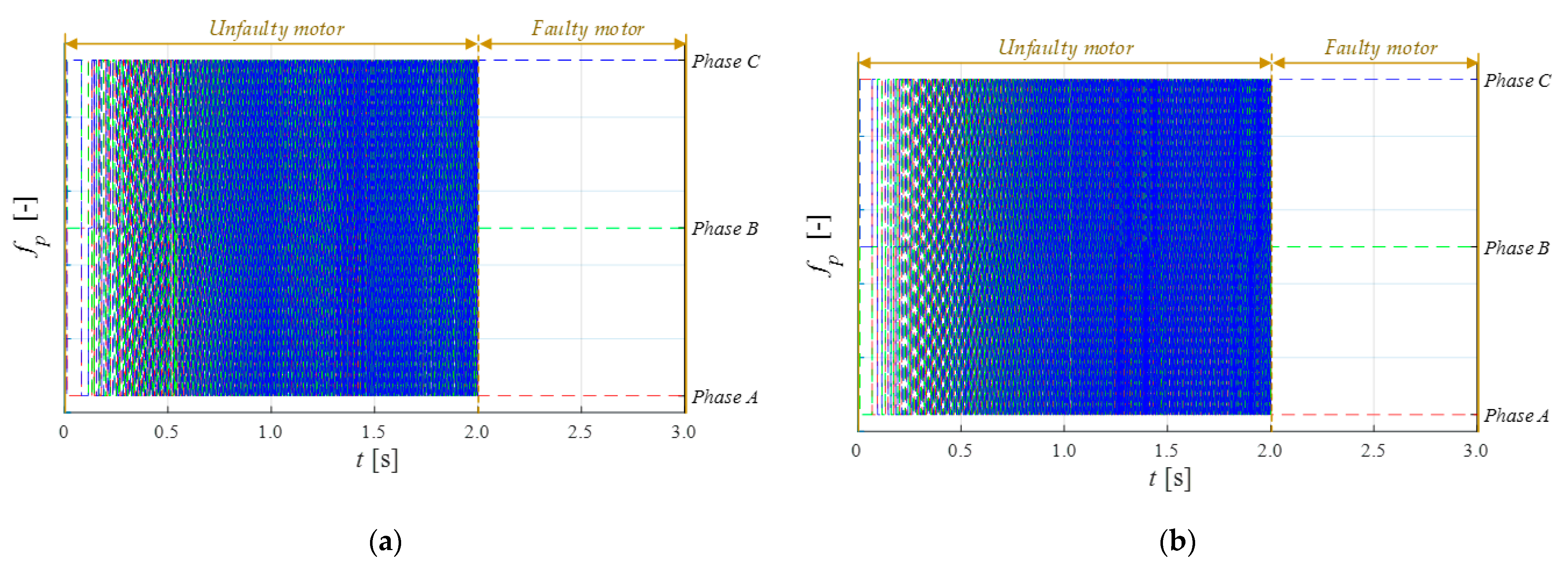
The minimum value found will correspond to an undamaged motor phase. Examples of simulation results are presented in Figure 17.
It should be emphasized that both the coil damage indicator fi and the damaged phase detector fp require calculations during the steady state of the drive system operation.
6. Conclusions
The article presents a detailed analysis of the impact of an inter-turn short circuit in the stator winding of a PMSM motor on the operation of the drive in a closed and open-loop control structure. The developed simulation model makes it possible to study the effects of inter-turn short-circuit in the PMSM motor for any phase of the stator winding, as well as to model the damage to the turn insulation. Based on the analysis of the simulation test results, it was shown that the impact of damage to the stator of the PMSM motor operating in the scalar and vector control structures is clearly visible. Based on the analysis of the stator current vector in the α-β stationary reference system, the compensatory effect of the closed control structure on the diagnostic signals during the occurrence of shorted turn was confirmed. However, the compensatory effect of the fundamental component of the stator current in the closed-loop control structure causes an increase in the third harmonic component of the stator current, 3fs, whose amplitudes achieve much greater values than in the open-loop scalar control structure. Nevertheless, the analysis of the stator current spectrum showed that the observation of the third harmonic amplitude of the fundamental component of the phase current provides information about the inter-turn short-circuit faults in the closed-loop control structure, even in the case of an incipient stage of the failure, regardless of the value of the motor load torque. The same conclusions apply to the harmonic component of the speed signal with the frequency of 2fs. The amplitude values of these harmonics can be used, for example, to train neural networks and to develop neural detectors of PMSM stator windings.
However, due to the requirement of signal stationarity during the FFT analysis and the complex process of neural detector design and training, an alternative may be the use of the proposed fault indicator, fi, which allows the detection of a few short turns (incipient fault) in the stator phase winding, as well as allows the detection of a damaged phase, fp, both in the vector and scalar PMSM control structure, under different loads.
Author Contributions
All of the authors contributed equally to the concept of the paper, and proposed the methodology; investigation and formal analyses, M.K., T.O.-K., and M.S.; software and data curation, M.K.; measurements, M.K. and M.S.; writing—original draft preparation, M.K. and T.O.-K.; writing—review and editing, T.O.-K.; supervision, project administration and funding acquisition, T.O.-K. All authors have read and agreed to the published version of the manuscript.
Funding
This research was funded by the National Science Centre Poland under Grant No. 2017/27/B/ST7/00816 and in part by statutory funds of the Department of Electrical Machines Drives and Measurements of Wroclaw University of Science and Technology.
Data Availability Statement
Not applicable.
Conflicts of Interest
The authors declare no conflict of interest.
Nomenclature
| Us | stator three-phase voltage vector of a healthy motor, |
| Usf | stator three-phase voltage vector of a motor with stator winding fault, |
| Us | magnitude of the stator voltage, |
| Is | stator three-phase current vector of a healthy motor, |
| Isf | stator three-phase current vector of a motor with stator winding fault, |
| Is | magnitude of the stator current, |
| If | current circulating in the shorted turns, |
| Rs | stator resistance matrix of a healthy stator winding, |
| Rsf | stator resistance matrix of a faulty stator winding, |
| Rs | stator phase resistance, |
| Ls | stator inductance matrix of a healthy stator winding, |
| Ls | stator phase self-inductance, |
| Ms | mutual inductance between stator phases, |
| Es | three-phase voltage vector induced by the stator flux linkage, |
| Es | magnitude of the voltage vector induced by the stator flux linkage, |
| Ψs | stator three-phase magnetic flux vector of a healthy motor, |
| ΨPM | stator three-phase magnetic flux vector due to permanent magnets, |
| ΨPM | permanent magnet flux, |
| Pe | input power, |
| Te | electromagnetic torque, |
| TL | load torque, |
| B | viscous friction coefficient, |
| J | drive system inertia, |
| fs | synchronous frequency, |
| pp | number of pole pairs, |
| N | total number of turns in a motor phase, |
| Nsf | number of shorted turns, |
| µ | coefficient of shorted turns (Nsf /N), |
| Ωm | mechanical speed of the motor, |
| θe | rotor electrical position, |
| θm | rotor mechanical position, |
| δ | load angle, |
| φ | angle between the stator voltage and current space vectors (power-factor angle), |
| fi | index of the failure in stator phases, |
| fp | index of the damaged phase, |
| PMSM | permanent magnet synchronous motor, |
| LPF | low pass filter, |
| HPF | high pass filter. |
Appendix A

Table A1.
The nominal parameters of the tested PMSM.
| Parameter | Symbol | Value | Unit |
|---|---|---|---|
| Nominal power | PN | 2500 | [W] |
| Nominal torque | TN | 16 | [Nm] |
| Nominal voltage | UN | 325 | [V] |
| Nominal current | IN | 6.6 | [A] |
| Nominal frequency | fN | 100 | [Hz] |
| Stator resistance | Rs | 1.206 | [Ω] |
| Stator inductance | Ls | 27.58 | [mH] |
| Mutual inductance | Ms | 7.02 | [mH] |
| Nominal speed | nN | 1500 | [rpm] |
| Number of pole pairs | pp | 4 | [-] |
| Total turns number in phase | Ns | 250 | [-] |
| Drive inertia | J | 1.42 | [kg∙cm2] |
References
- Commission Regulation (EU) 2019/1781 of 1 October 2019 laying down ecodesign requirements for electric motors and variable speed drives pursuant to Directive 2009/125/EC of the European Parliament and of the Council, amending Regulation (EC) No 641/2009 with regard to ecodesign requirements for glandless standalone circulators and glandless circulators integrated in products and repealing Commission Regulation (EC) No 640/2009. Off. J. Eur. Union 2019, 62, 74–94.
- Liu, W.; Chen, S.; Huang, H. Adaptive Nonsingular Fast Terminal Sliding Mode Control for Permanent Magnet Synchronous Motor Based on Disturbance Observer. IEEE Access 2019, 7, 153791–153798. [Google Scholar] [CrossRef]
- He, J.; Somogyi, C.; Strandt, A.; Demerdash, N.A. Diagnosis of stator winding short-circuit faults in an interior permanent magnet synchronous machine. In Proceedings of the 2014 IEEE Energy Conversion Congress and Exposition (ECCE), Pittsburgh, PA, USA, 14–18 September 2014; pp. 3125–3130. [Google Scholar]
- Maraaba, L.S.; Al-Hamouz, Z.M.; Abido, M.A. Mathematical Modeling, Simulation and Experimental Testing of Interior-Mount LSPMSM Under Stator Inter-Turn Fault. IEEE Trans. Energy Convers. 2019, 34, 1213–1222. [Google Scholar] [CrossRef]
- Nandi, S.; Toliyat, H.A.; Li, X. Condition Monitoring and Fault Diagnosis of Electrical Motors—A Review. IEEE Trans. Energy Convers. 2005, 20, 719–729. [Google Scholar] [CrossRef]
- Henao, H.; Demian, C.; Capolino, G.A. A frequency-domain detection of stator winding faults in induction machines using an external flux sensor. IEEE Trans. Ind. Appl. 2003, 39, 1272–1279. [Google Scholar] [CrossRef]
- Cruz, S.M.A.; Cardoso, A.J.M. Stator Winding Fault Diagnosis in Three-Phase Synchronous and Asynchronous Motors, by the Extended Park’s Vector Approach. IEEE Trans. Ind. Appl. 2001, 37, 1227–1233. [Google Scholar] [CrossRef]
- Wolkiewicz, M.; Tarchała, G.; Orłowska-Kowalska, T.; Kowalski, C.T. Online stator interturn short circuits monitoring in the DFOC induction-motor drive. IEEE Trans. Ind. Electron. 2016, 63, 2517–2528. [Google Scholar] [CrossRef]
- Rosero, J.A.; Romeral, L.; Ortega, J.A.; Rosero, E. Short-circuit detection by means of empirical mode decomposition and Wigner–Ville distribution for PMSM running under dynamic condition. IEEE Trans. Ind. Electron. 2009, 56, 4534–4547. [Google Scholar] [CrossRef]
- Usman, A.; Joshi, B.M.; Rajpurohit, B.S. Review of fault modelling methods for permanent magnet synchronous motors and their comparison. In Proceedings of the 2017 IEEE 11th International Symposium on Diagnostics for Electrical Machines, Power Electronics and Drives (SDEMPED), Tinos, Greece, 29 August–1 September 2017. [Google Scholar]
- Mazzoletti, M.A.; Bossio, G.R.; De Angelo, C.H.; Espinoza-Trejo, D.R. A model-based strategy for interturn short-circuit fault diagnosis in PMSM. IEEE Trans. Ind. Electron. 2017, 64, 7218–7228. [Google Scholar] [CrossRef]
- Gao, Z.; Cecati, C.; Ding, S.X. A survey of fault diagnosis and fault-tolerant techniques—Part I: Fault diagnosis with model-based and signal-based approaches. IEEE Trans. Ind. Electron. 2015, 62, 3757–3767. [Google Scholar] [CrossRef] [Green Version]
- Capolino, G.A.; Romary, R.; Hénao, H.; Pusca, R. State of the Art on Stray Flux Analysis in Faulted Electrical Machines. In Proceedings of the 2019 IEEE Workshop on Electrical Machines Design, Control and Diagnosis (WEMDCD), Athens, Greece, 22–23 April 2019. [Google Scholar]
- Ebrahimi, B.M.; Faiz, J. Feature Extraction for Short-Circuit Fault Detection in Permanent-Magnet Synchronous Motors Using Stator-Current Monitoring. IEEE Trans. Power Electron. 2010, 25, 2673–2682. [Google Scholar] [CrossRef]
- Skowron, M.; Wolkiewicz, M.; Orlowska-Kowalska, T.; Kowalski, C.T. Application of Self-Organizing Neural Networks to Electrical Fault Classification in Induction Motors. Appl. Sci. 2019, 9, 616. [Google Scholar] [CrossRef] [Green Version]
- Wen, L.; Li, X.; Gao, L.; Zhang, Y. A New Convolutional Neural Network-Based Data-Driven Fault Diagnosis Method. IEEE Trans. Ind. Electron. 2018, 65, 5990–5998. [Google Scholar] [CrossRef]
- Kao, I.; Wang, W.; Lai, Y.; Perng, J. Analysis of Permanent Magnet Synchronous Motor Fault Diagnosis Based on Learning. IEEE Trans. Instrum. Meas. 2019, 68, 310–324. [Google Scholar] [CrossRef]
- Skowron, M.; Orlowska-Kowalska, T.; Wolkiewicz, M.; Kowalski, C.T. Convolutional Neural Network Based Incipient Stator Fault Detection of Inverter-Fed Induction Motor Using Stator Current Measurement. Energies 2020, 13, 1475. [Google Scholar] [CrossRef] [Green Version]
- Gandhi, A.; Corrigan, T.; Parsa, L. Recent advances in modelling and online detection of stator interturn faults in electrical motors. IEEE Trans. Ind. Electron. 2010, 58, 1564–1575. [Google Scholar] [CrossRef]
- Haddad, R.Z.; Strangas, E.G. On the accuracy of fault detection and separation in permanent magnet synchronous machines using MCSA/MVSA and LDA. IEEE Trans. Energy Convers. 2016, 31, 924–934. [Google Scholar] [CrossRef]
- Boileau, T.; Leboeuf, N.; Nahid-Mobarakeh, B.; Meibody-Tabar, F. Synchronous demodulation of control voltages for stator interturn fault detection in PMSM. IEEE Trans. Power Electron. 2013, 28, 5647–5654. [Google Scholar] [CrossRef]
- Zhang, J.; Zhan, W.; Ehsani, M. Fault-Tolerant Control of PMSM With Inter-Turn Short-Circuit Fault. IEEE Trans. Energy Convers. 2019, 34, 2267–2275. [Google Scholar] [CrossRef]
- Hang, J.; Ding, S.; Zhang, J.; Cheng, M.; Chen, W.; Wang, Q. Detection of interturn short-circuit fault for PMSM with simple fault indicator. IEEE Trans. Energy Convers. 2016, 31, 1697–1699. [Google Scholar] [CrossRef]
- Hang, J.; Zhang, J.; Cheng, M.; Huang, J. Online interturn fault diagnosis of permanent magnet synchronous machine using zero-sequence components. IEEE Trans. Power Electron. 2015, 30, 6731–6741. [Google Scholar] [CrossRef]
- Vas, P. Sensorless Vector and Direct Torque Control; Oxford University Press: London, UK, 1998; pp. 5–81. [Google Scholar]
- Romeral, L.; Urresty, J.C.; Riba Ruiz, J.R.; Garcia Espinosa, A. Modelling of surface-mounted permanent magnet synchronous motors with stator winding interturn faults. IEEE Trans. Ind. Electron. 2011, 58, 1576–1585. [Google Scholar] [CrossRef]
- Perera, P.D.C.; Blaabjerg, F.; Pedersen, J.K.; Thogersen, P. A sensorless, stable V/f control method for permanent-magnet synchronous motor drives. IEEE Trans. Ind. Appl. 2003, 39, 783–791. [Google Scholar] [CrossRef]
Figure 1.
Equivalent circuit of the PMSM stator winding with shorted turns in phase A.
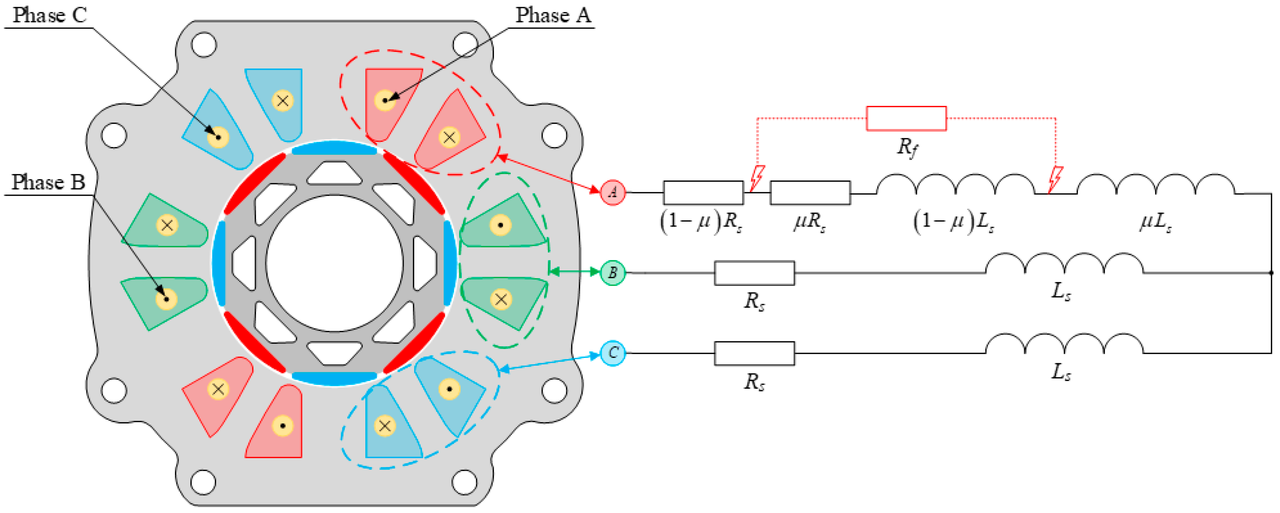
Figure 2.
Experimental verification of the proposed mathematical model of PMSM with short circuits in the stator winding: (a) instantaneous occurring of the shorted turns; (b) instantaneous occurring of the shorted turns—zoom; TL = TN, fs = 100 Hz.
Figure 2.
Experimental verification of the proposed mathematical model of PMSM with short circuits in the stator winding: (a) instantaneous occurring of the shorted turns; (b) instantaneous occurring of the shorted turns—zoom; TL = TN, fs = 100 Hz.
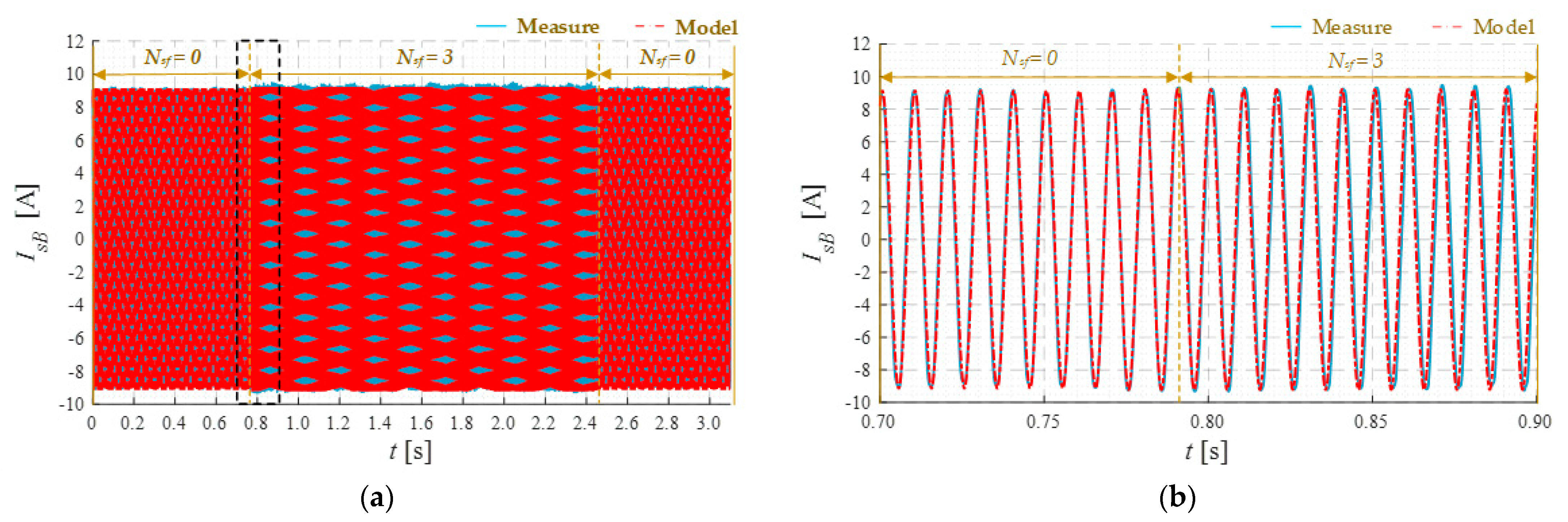
Figure 3.
The spectral analysis of the PMSM stator current in phase B: (a) simulation results; (b) experimental results; TL = TN, fs = 100 Hz.
Figure 3.
The spectral analysis of the PMSM stator current in phase B: (a) simulation results; (b) experimental results; TL = TN, fs = 100 Hz.

Figure 4.
Vector diagram of PMSM for steady-state.
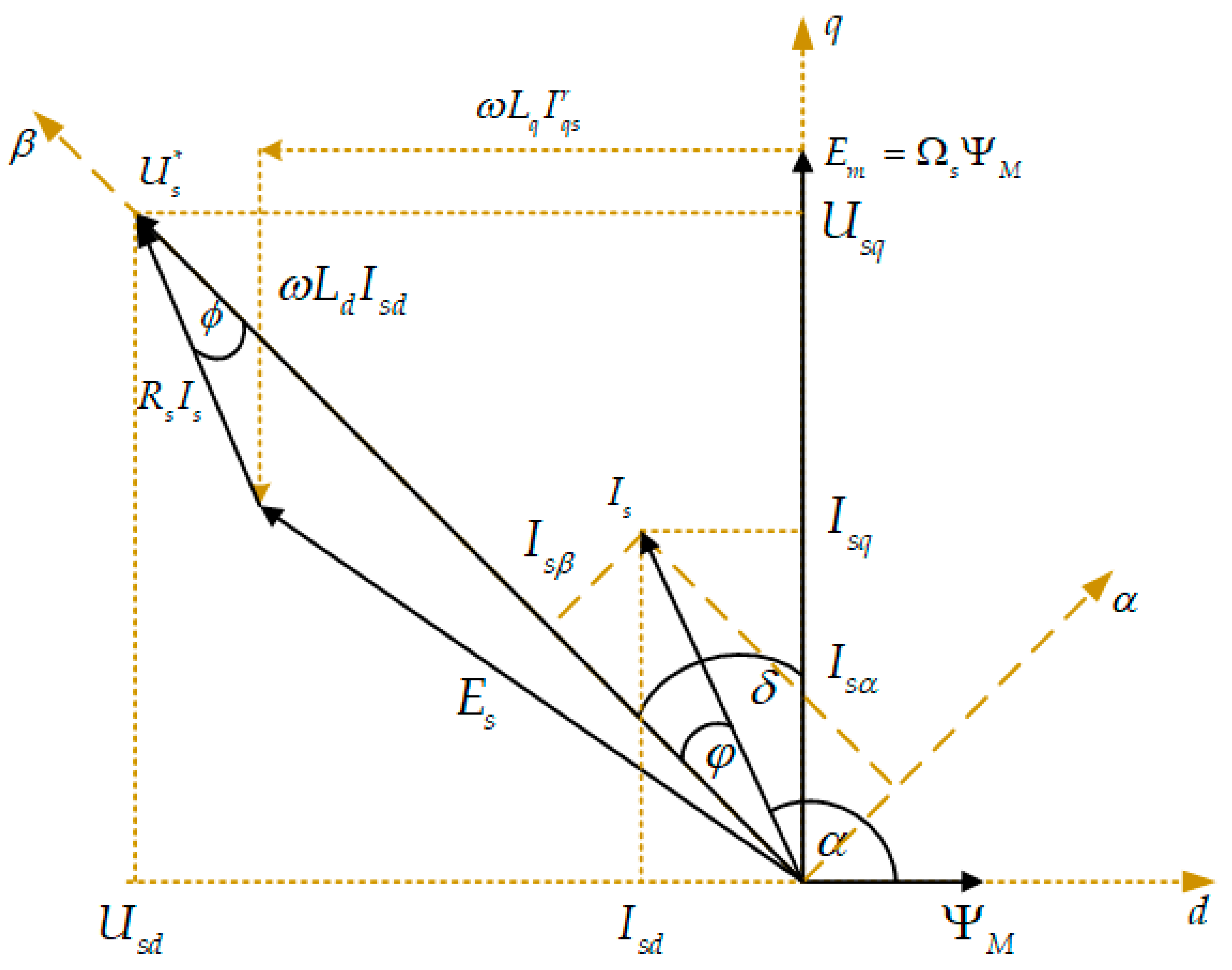
Figure 5.
Stator voltage calculation with Rs—voltage drop and load torque compensation.

Figure 6.
Scheme of the field-oriented control of the PMSM drive.
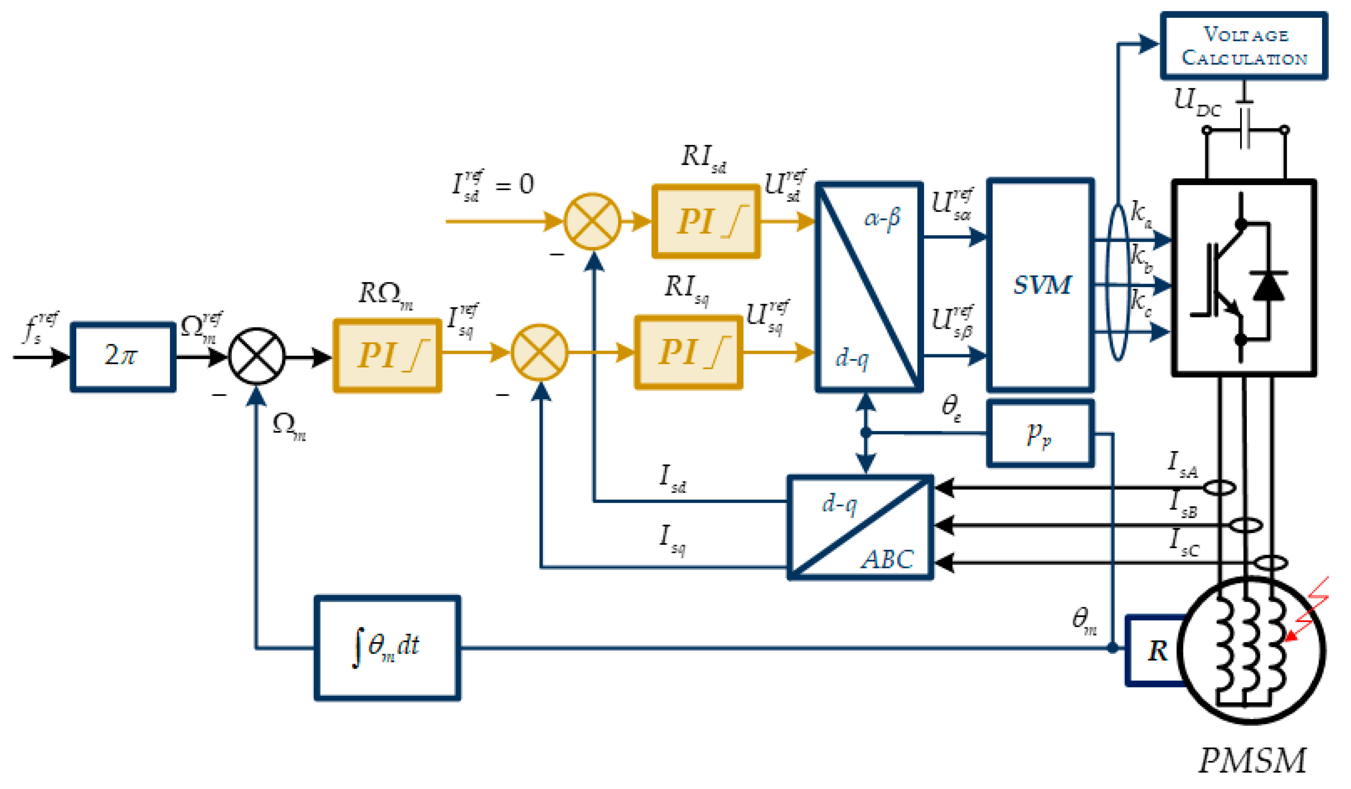
Figure 7.
Waveforms of undamaged motor state variables for different values of the load torque, TL = (0–1)TN and for fs = 100 Hz in the scalar control structure (open system with load torque compensation): (a,c,e) and in the field-oriented control structure: (b,d,f). Transients of the rotor speed (a,b), phase current (c,d), electromagnetic, and load torques (e,f).

Figure 8.
Phase current waveforms at the moment of short-circuit Nsf=5 turns in the PMSM motor for fs = 100 Hz, TL = 0.2 TN: scalar control (open system with load torque compensation) (a), field-oriented control (b).
Figure 8.
Phase current waveforms at the moment of short-circuit Nsf=5 turns in the PMSM motor for fs = 100 Hz, TL = 0.2 TN: scalar control (open system with load torque compensation) (a), field-oriented control (b).
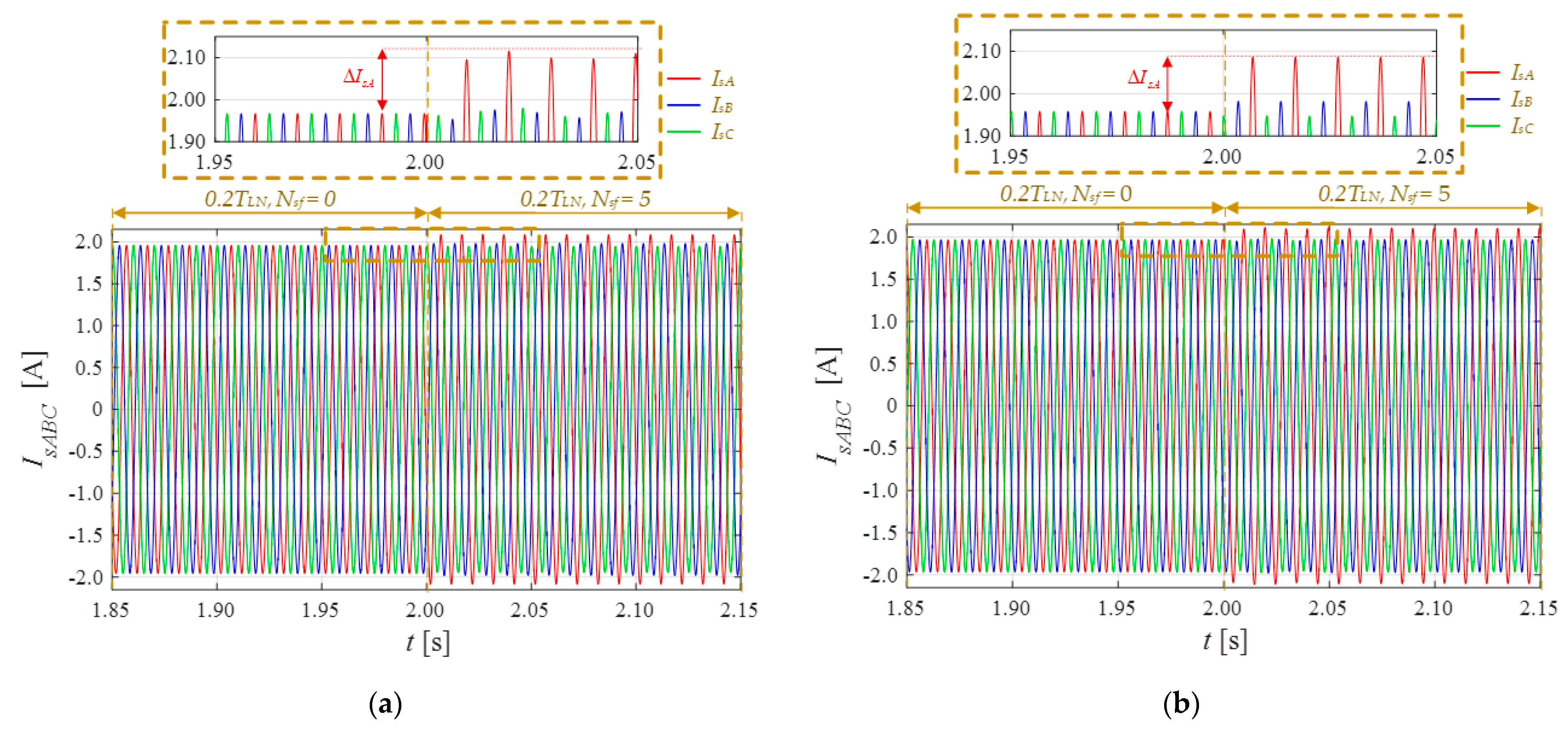
Figure 9.
The current space vector hodograph for an undamaged and a damaged motor: scalar control (a), field-oriented control (b); 5 and 8 shorted turns in stator winding; fs = 100 Hz.
Figure 9.
The current space vector hodograph for an undamaged and a damaged motor: scalar control (a), field-oriented control (b); 5 and 8 shorted turns in stator winding; fs = 100 Hz.

Figure 10.
Transients of the electromagnetic torque and load torque for the faulty PMSM, Nsf = 8, fs = 100 Hz: scalar control (a), field-oriented control (b).
Figure 10.
Transients of the electromagnetic torque and load torque for the faulty PMSM, Nsf = 8, fs = 100 Hz: scalar control (a), field-oriented control (b).

Figure 11.
Dependence of the fundamental harmonic of the stator current amplitude, fs, on the number of shorted turns and the load torque values for fs = 100 Hz: scalar control (a), field-oriented control (b).
Figure 11.
Dependence of the fundamental harmonic of the stator current amplitude, fs, on the number of shorted turns and the load torque values for fs = 100 Hz: scalar control (a), field-oriented control (b).
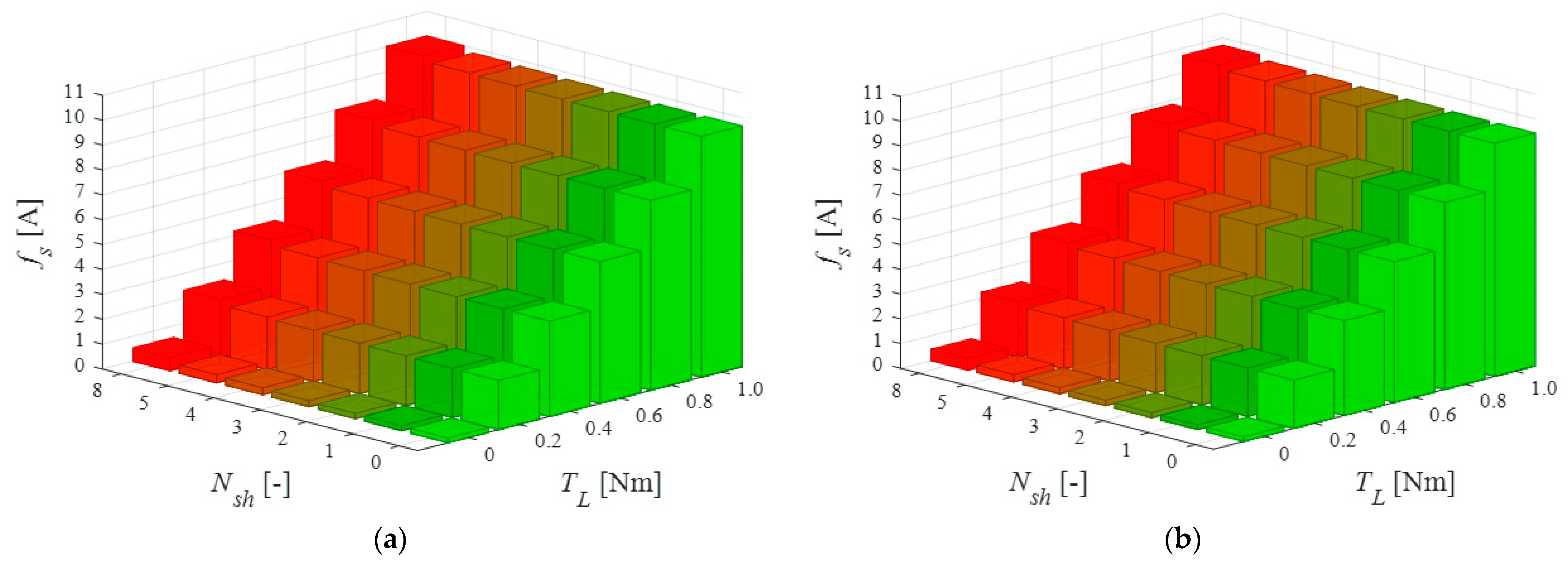
Figure 12.
Dependence of the 3rd harmonic of the stator current amplitude, 3fs, on the number of shorted turns and the load torque values for fs = 100 Hz: scalar control (a), field-oriented control (b).
Figure 12.
Dependence of the 3rd harmonic of the stator current amplitude, 3fs, on the number of shorted turns and the load torque values for fs = 100 Hz: scalar control (a), field-oriented control (b).
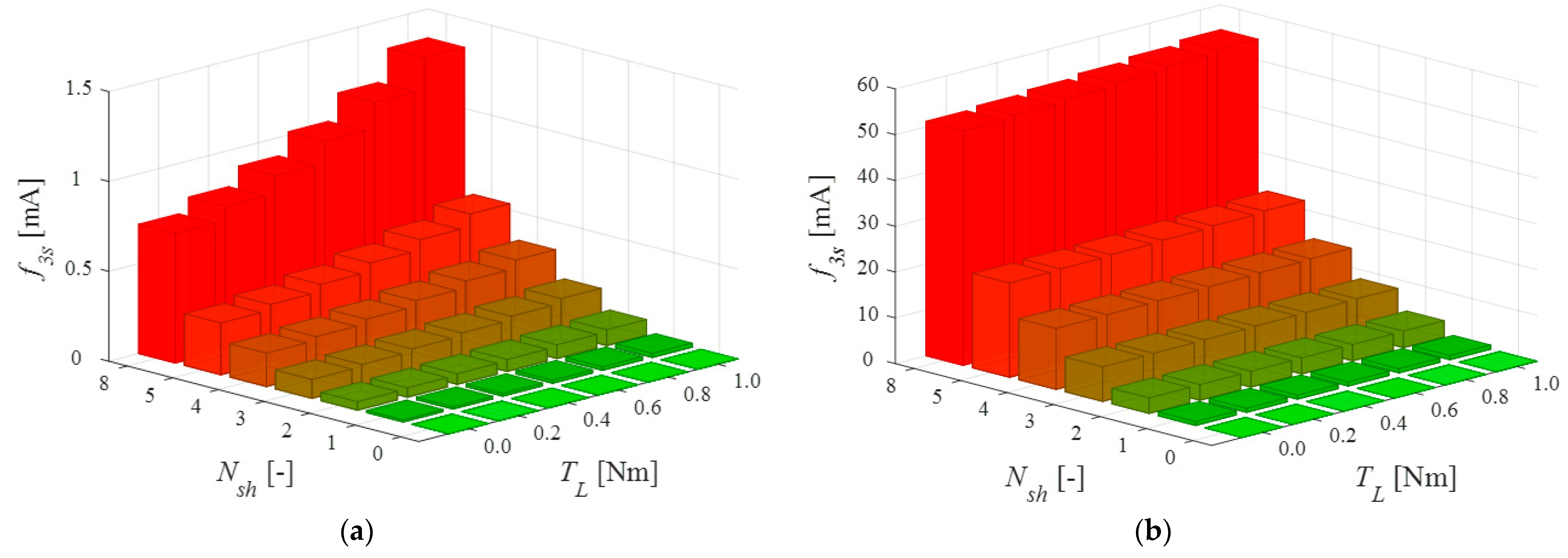
Figure 13.
Dependence of the 2nd harmonic of the rotor speed, 2fs, on the number of shorted turns and the load torque values for fs = 100 Hz: scalar control (a), field-oriented control (b).
Figure 13.
Dependence of the 2nd harmonic of the rotor speed, 2fs, on the number of shorted turns and the load torque values for fs = 100 Hz: scalar control (a), field-oriented control (b).
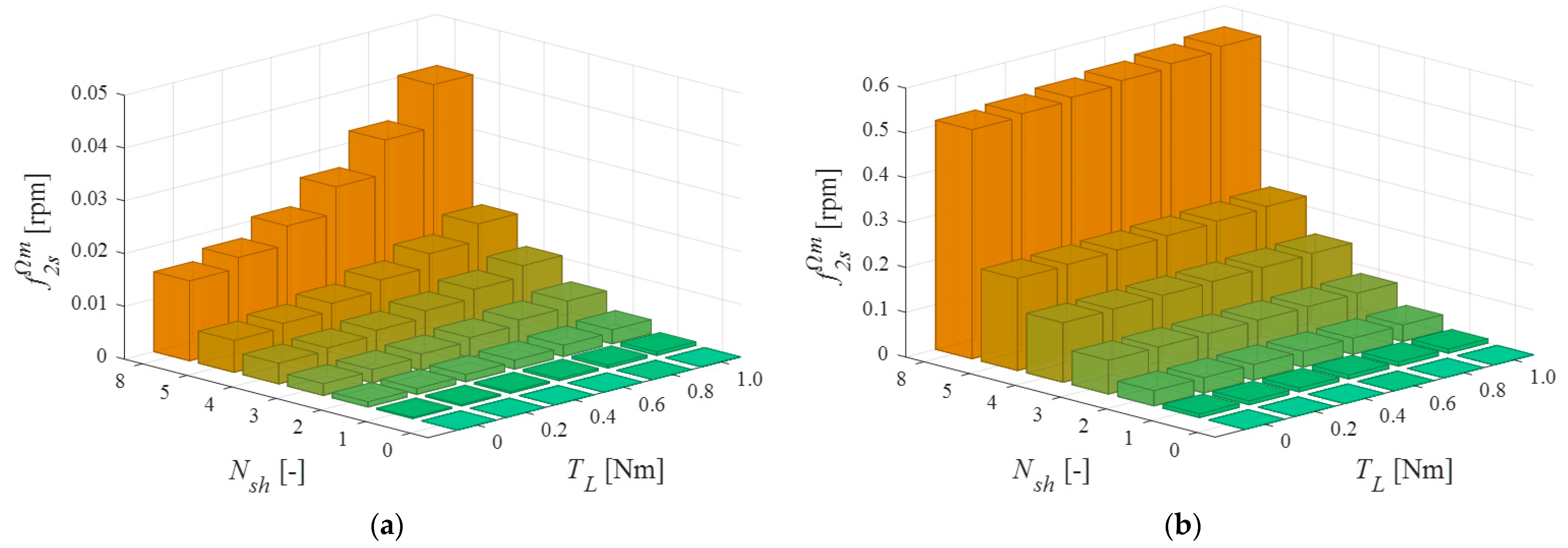
Figure 14.
Waveforms of the failure index fi for the operating frequency fs =100 Hz: scalar control (a,c,e); field-oriented control (b,d,f); for different load torque values: TL ≈ 0 (a,b); TL = 0.6TN (c,d); TL = TN (e,f).
Figure 14.
Waveforms of the failure index fi for the operating frequency fs =100 Hz: scalar control (a,c,e); field-oriented control (b,d,f); for different load torque values: TL ≈ 0 (a,b); TL = 0.6TN (c,d); TL = TN (e,f).
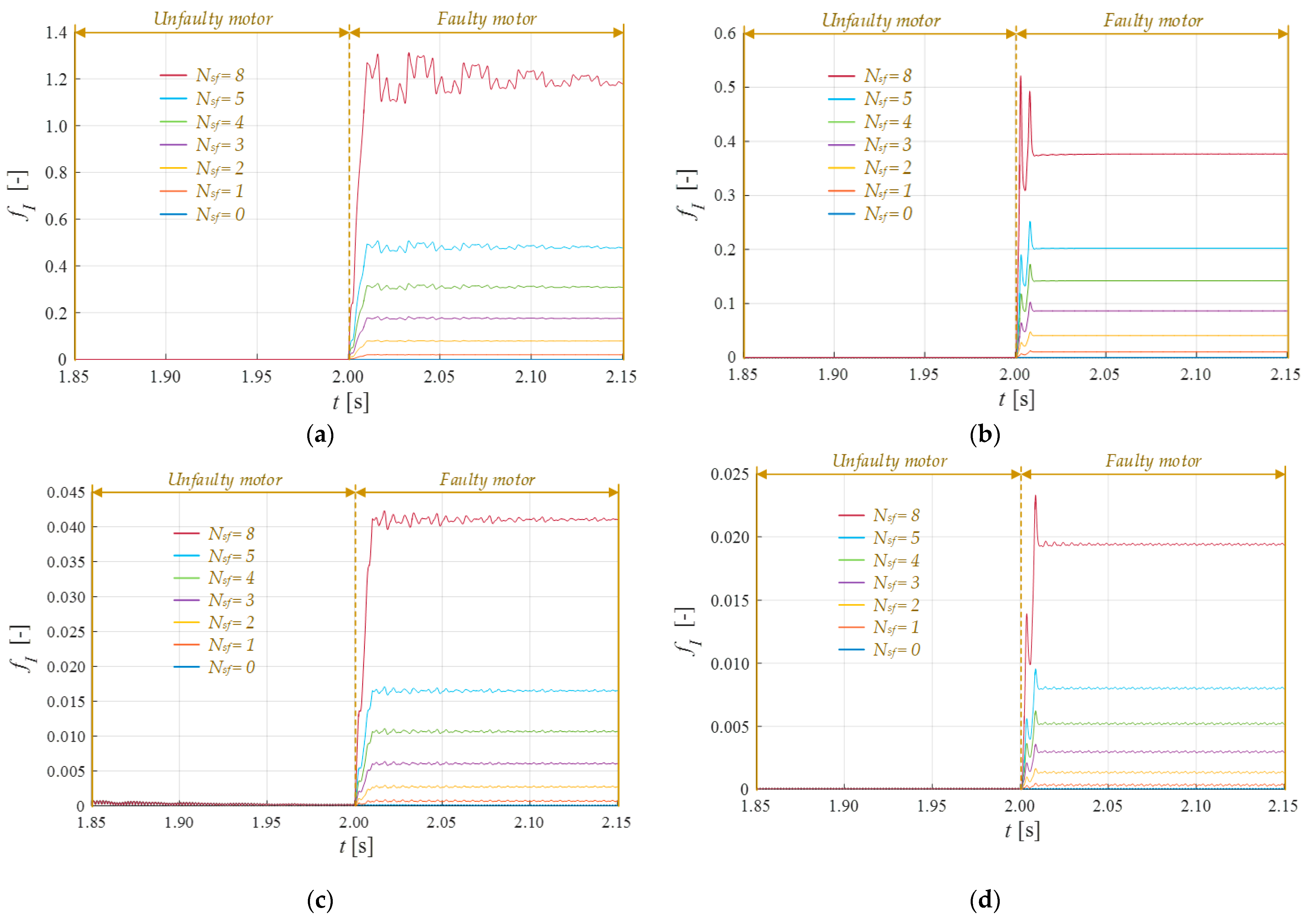
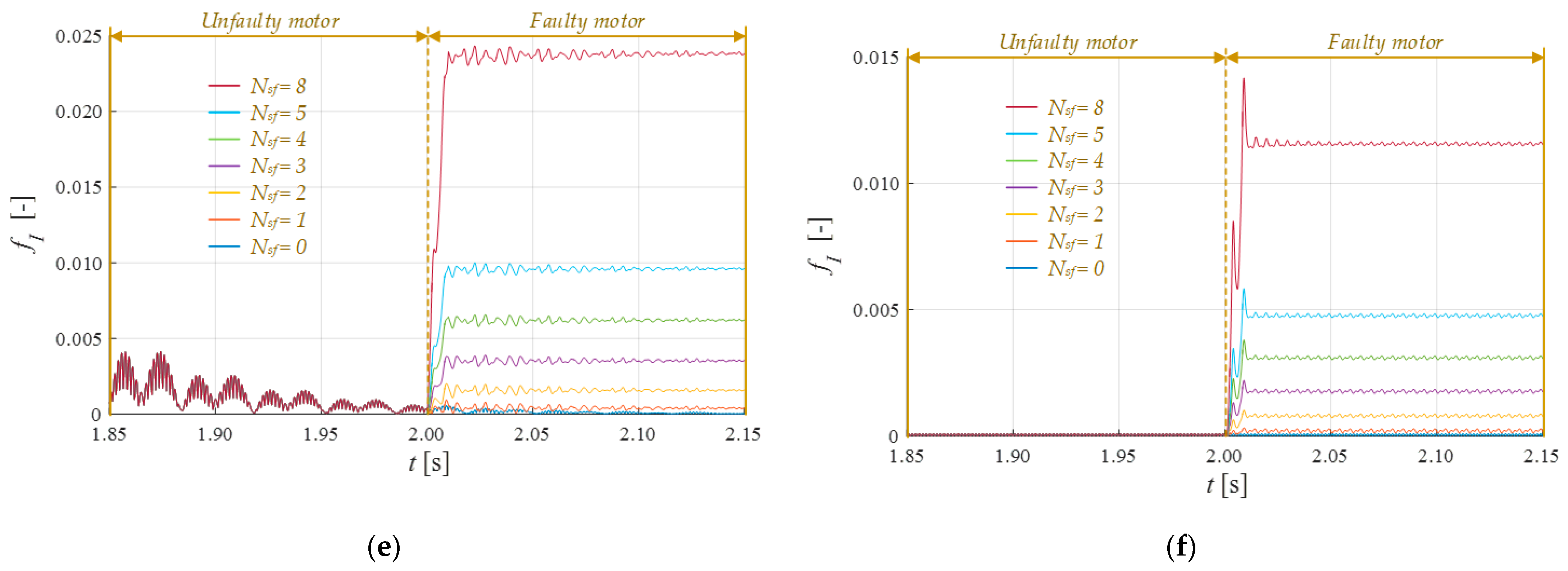
Figure 15.
Dependence of the failure index, fi, on the number of shorted turns and the VSI frequency for TL ≈ 0: scalar control (a), field-oriented control (b).
Figure 15.
Dependence of the failure index, fi, on the number of shorted turns and the VSI frequency for TL ≈ 0: scalar control (a), field-oriented control (b).
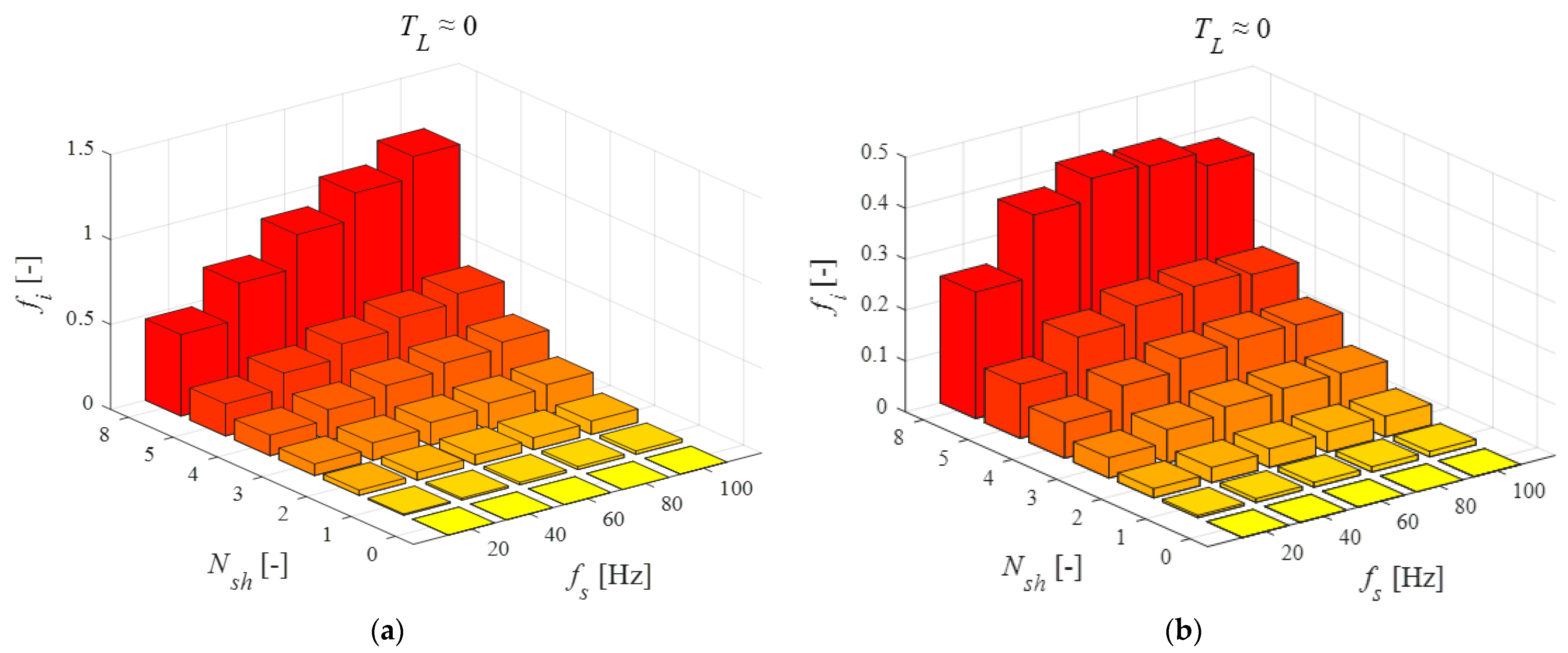
Figure 16.
Dependence of the failure index in the field-oriented control, on the number of shorted turns and the voltage frequency for: TL = 0.6TN (a), TL = TN (b).
Figure 16.
Dependence of the failure index in the field-oriented control, on the number of shorted turns and the voltage frequency for: TL = 0.6TN (a), TL = TN (b).

Figure 17.
Waveforms of the failure index fp for the operating frequency fs = 100 Hz, TL ≈ 0: scalar control (a); field-oriented control (b); an example of the inter-turn short-circuit in the phase A, Nsf = 1.
Figure 17.
Waveforms of the failure index fp for the operating frequency fs = 100 Hz, TL ≈ 0: scalar control (a); field-oriented control (b); an example of the inter-turn short-circuit in the phase A, Nsf = 1.
Publisher’s Note: MDPI stays neutral with regard to jurisdictional claims in published maps and institutional affiliations. |
© 2020 by the authors. Licensee MDPI, Basel, Switzerland. This article is an open access article distributed under the terms and conditions of the Creative Commons Attribution (CC BY) license (http://creativecommons.org/licenses/by/4.0/).
Share and Cite
MDPI and ACS Style
Krzysztofiak, M.; Skowron, M.; Orlowska-Kowalska, T. Analysis of the Impact of Stator Inter-Turn Short Circuits on PMSM Drive with Scalar and Vector Control. Energies 2021, 14, 153. https://doi.org/10.3390/en14010153
AMA Style
Krzysztofiak M, Skowron M, Orlowska-Kowalska T. Analysis of the Impact of Stator Inter-Turn Short Circuits on PMSM Drive with Scalar and Vector Control. Energies. 2021; 14(1):153. https://doi.org/10.3390/en14010153
Chicago/Turabian StyleKrzysztofiak, Mateusz, Maciej Skowron, and Teresa Orlowska-Kowalska. 2021. "Analysis of the Impact of Stator Inter-Turn Short Circuits on PMSM Drive with Scalar and Vector Control" Energies 14, no. 1: 153. https://doi.org/10.3390/en14010153
Note that from the first issue of 2016, this journal uses article numbers instead of page numbers. See further details here.