
Optimal Scheduling Strategy of AC/DC Hybrid Distribution Network Based on Power Electronic Transformer


State Key Lab of Power Systems, Department of Electrical Engineering, Tsinghua University, Beijing 100084, China
*
Author to whom correspondence should be addressed.
Energies 2021, 14(11), 3219; https://doi.org/10.3390/en14113219
Submission received: 20 April 2021
/
Revised: 27 May 2021
/
Accepted: 27 May 2021
/
Published: 31 May 2021
(This article belongs to the Topic Innovative Techniques for Smart Grids)
Abstract
:The AC/DC hybrid distribution network is composed of a medium-voltage DC bus, a low-voltage DC bus, and a power electronic transformer, and has the characteristics of multi-voltage level, multi-DC bus, and multi-converter, so its operation mode and optimal scheduling strategy are more complex. Firstly, this paper constructs the AC/DC hybrid distribution network using an power electronic transformer. Then, a two-layer control structure including a scheduling management layer and a bus control layer is proposed, which simplifies the control structure and gives full play to the role of “energy routing” function of the power electronic transformer. Moreover, the minimum operation cost of the AC/DC hybrid distribution network in the whole scheduling cycle is taken as the optimization objective, considering the characteristics of various distributed generations, the structure of AC/DC hybrid distribution network, and the interaction of “source–load–storage”. Finally, the optimal scheduling model of the AC/DC hybrid distribution network based on power electronic transformer is established, and the feasibility of the optimal scheduling strategy is verified by the open-source solver, which can realize the complete absorption of renewable energy and the optimal coordinated control of “source–load–storage”.
1. Introduction
With the development of distribution network, the increase of DC load, the increasingly extensive application of energy storage, the problems of high AC/DC energy conversion loss, and the poor flexibility of the distribution network in the traditional AC distribution network have become increasingly prominent. In addition, with the high requirements of customers for power quality and supply reliability, the traditional AC distribution network will encounter new challenges in terms of stability and economy in power supply, and it is unable to meet the ever-changing demand for DC power and electricity uses. The AC/DC hybrid distribution network has the advantages of flexible power scheduling, high system efficiency, large power capacity, low line loss, high power quality, and reactive power compensation. Moreover, it is suitable for distributed generation, energy storage devices, and DC loads to access flexibly; helps to solve a series of new problems in the development of traditional AC distribution network; and is important in developing the direction of the power distribution network [1,2,3,4,5].
Due to the integration of distributed generation, energy storage, grid connected inverter, and various loads in the AC/DC hybrid distribution network, and considering the intermittence of the distributed generation, the stable operation of the network is closely related to the coordinated control of each power supply. References [6,7,8,9,10,11,12,13,14,15,16] propose various coordinated control strategies, which can be divided into two types: centralized coordinated control strategy and distributed coordinated control strategy. The centralized coordinated control strategy is highly dependent on communication, and the upper management system needs to keep in touch with each module unit and determine its working mode and output, to maintain the power balance of the system and realize optimal operation [6,7]. The distributed centralized control strategy does not require communication, and each module in the system adjusts the working mode according to the signal of DC bus voltage to jointly maintain the stability of DC bus. It is a simple control, but the fluctuation range of DC bus voltage is large and its economy is poor [8,9]. In order to solve these problems, reference [10] proposes a control strategy based on power capacity for bus voltage interval division and droop coefficient real-time adjustment, which further reduces the deviation value of bus voltage. Reference [11] uses energy storage to stabilize the DC bus voltage, avoiding the adverse effects caused by the switching of the voltage stabilization control unit, but it requires a higher capacity for energy storage. In reference [12], a second-order DC voltage deviation controller is added to the battery charging and discharging control loop, which can control the DC voltage to a constant value without switching between multiple control loops. References [13,14,15] propose a layered control strategy, which combines distributed control with upper management, improving the reliability and enhancing the economy of the system. However, this layered control strategy is mainly aimed at low-voltage DC microgrid and is not suitable for the research object of this article, that is, the AC/DC hybrid distribution network based on power electronic transformers. In summary, scholars have conducted extensive research on the coordinated control strategy of the AC/DC power distribution network.
With the development of power electronic transformers [16,17,18,19], the AC/DC hybrid distribution network based on power electronic transformers has become a new way to construct the AC/DC hybrid distribution network. The topology of a typical three-port power electronic transformer is shown in Figure 1. It has advantages such as flexible power control, high permeability of new energy to access, high power quality, and reactive power compensation. However, the change of network topology of the AC/DC hybrid distribution system poses new challenges to the typical power supply mode and control and protection technology of the system. At present, the operation mode and coordinated control strategy of the AC/DC hybrid distribution network based on power electronic transformer have not been systematically studied.
On the basis of the existing research work, this paper proposes an optimal scheduling strategy for AC/DC hybrid distribution network based on power electronic transformers. In Section 2, the topology and control structure of the AC/DC hybrid distribution network are introduced. In Section 3, the scheduling strategy for AC/DC hybrid distribution network is proposed, which takes the minimum operation cost of the AC/DC hybrid distribution network in the whole scheduling cycle as the optimization objective, considering the characteristics of various distributed generation; the structure of AC/DC hybrid distribution system; and the interaction of “source–load–storage”, the optimal scheduling model of the AC/DC hybrid distribution network based on power electronic transformer is established. In Section 3, the bus control strategy of the DC microgrid and the AC microgrid is proposed. In Section 4, the open-source solver is used to solve the optimal scheduling model to verify the feasibility of optimal scheduling strategy.
2. AC/DC Hybrid Distribution Network
2.1. Topology
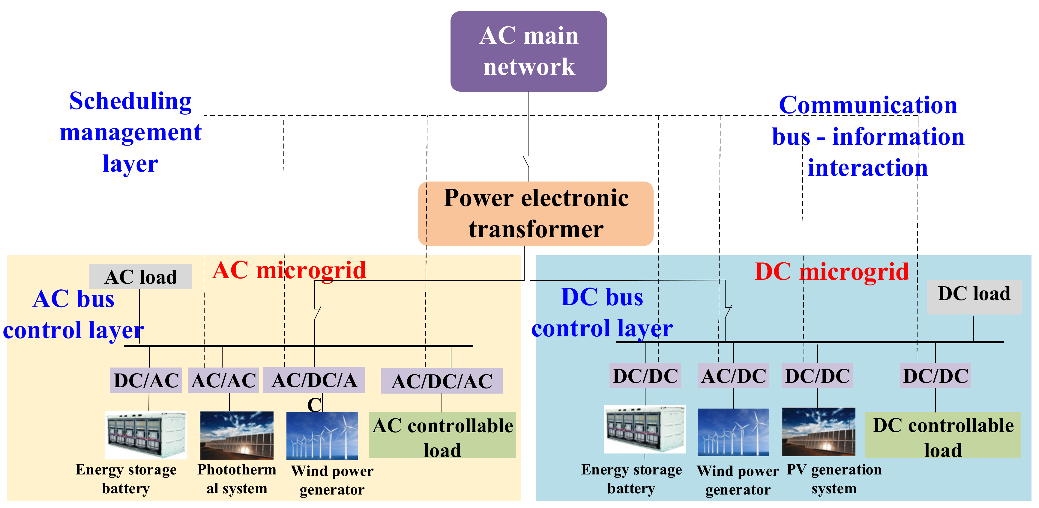
A typical AC/DC hybrid distribution network based on power electronic transformer is shown in Figure 2, which is mainly composed of a power electronic transformer, an AC microgrid, and a DC microgrid. The power electronic transformer is the junction between the microgrid and the AC main network, which has three ports: one medium voltage AC port, one low-voltage AC port, and one low-voltage DC port. The low-voltage AC port provides the AC bus for the AC microgrid, and the low-voltage DC port provides DC bus for the DC microgrid.
Among them, the DC microgrid technology represents the future development trend of distributed energy supply systems and is an important part of the future intelligent power distribution system, which can greatly improve the ability of the distribution network to absorb new energy, distributed power, and multiple loads.
2.2. Control Structure
According to different control objectives, coordination mechanisms, and response times, and referring to the control scheme of the AC distribution network [11,12], a two-layer control structure for the AC/DC hybrid distribution network based on power electronic transformer is proposed. The control system of the distribution network can be divided into a scheduling management layer and a bus control layer, as shown as Figure 2. Compared with the traditional control structure of the AC distribution network, the two-layer control structure for the AC/DC hybrid distribution network is simple. It can give full play to the role of “energy routing” function of power electronic transformer and realize the coordinated management of energy at the public connection point by using the power electronic transformer. This structure is consistent with the physical characteristics of the AC/DC hybrid distribution network, which provides a foundation for improving the reliability and intelligence of the control system.
The functions of the bus control are to ensure the stability of the AC voltage, AC frequency, and DC voltage; maintain the power balance in their respective systems; control the transmission power between the microgrid and the AC main network in the grid-connected mode; and realize the local autonomy of the microgrid. The power electronic transformer maintains the constant voltage of the medium-voltage (MV) DC bus. At the same time, it collects the transmission power of the DC/AC inverter and DC/DC converter and receives information from the AC power distribution management system. Aiming at minimizing the operating cost of the AC/DC hybrid distribution network, interconnection-power constraints are issued to the microgrid. The scheduling controller conducts real-time scheduling according to the optimization results of the AC microgrid control and DC microgrid control, interacts in operation state, and realizes collaborative optimization among systems [9].
3. Scheduling Management
In the scheduling management layer of the AC/DC hybrid distribution network based on power electronic transformers, the operation boundary of the AC/DC hybrid distribution network is taken as the constraint and the lowest operating cost is taken as the objective function to establish the optimal scheduling model, which can realize the overall optimal control of the AC/DC hybrid distribution network. Through optimization, the power commands of each controllable unit in the AC/DC hybrid distribution network can be obtained. The top-level central control unit issues scheduling commands through the communication link to control the behavior of each unit to make the AC/DC hybrid distribution network operate safely, reliably, and economically when the constraints are met [12,13].
Therefore, the optimal model of the scheduling management layer of the AC/DC hybrid distribution network can be expressed as
where is the decision variable, including the output of various distributed generation; is an equality constraint; and is an inequality constraint.
3.1. The Objective Function
The day ahead optimal scheduling of the AC/DC hybrid distribution network based on power electronic transformer considers the boundary conditions such as the supply balance constraint of load demand, the capacity constraint of all kinds of equipment, the operation constraint of equipment, and the safe and stable operation constraint of system, to realize the lowest operation cost of the AC/DC hybrid distribution network in the whole scheduling cycle. The cost of the entire AC/DC hybrid distribution network includes the distributed generation operating cost , the photothermal system operating cost , the power purchase cost , and the compensation cost for controllable load reduction . Therefore:
3.1.1. Distributed Generation Operating Cost
The distributed generation operating cost consists of photovoltaic system operating cost , wind power system operating cost , and power storage operating cost , given as
The distributed generation operating cost is usually divided into two parts [6,7]: one is the investment cost of distributed generation converted to the cost of each day, and the other is the operation and maintenance cost of distributed generation:
where , , and , respectively, represent the investment cost of photovoltaic system, wind power system, and power storage system, converted to the cost of each day. , , and , respectively, represent the daily operating and maintenance costs of photovoltaic system, wind power system, and power storage system.
The investment cost of distributed generation is converted to the cost of each day, which is related to the depreciation rate, the service life of distributed generation, and installation cost. The investment cost of distributed generation is converted to the cost of each day as follows:
where , , and , respectively, represent the investment costs of photovoltaic system, wind power system, and energy storage system; , , and , respectively, represent the depreciation rates of photovoltaic system, wind power system, and energy storage system; , , and , respectively, represent the service life of photovoltaic system, wind power system, and energy storage system; , , and , respectively, represent the annual maximum utilization hours of photovoltaic system, wind power system, and energy storage system; and , , and , respectively, represent the actual generated power of photovoltaic system, wind power system, and energy storage system at t.
The operating cost and maintenance cost of distributed generation is mainly related to manual maintenance of distributed generation. Equation (6) represents the operating cost and maintenance cost of distributed generation:
where, , , and , respectively, represent the operating and maintenance factors of photovoltaic system, wind power system, and energy storage system.
3.1.2. Photothermal System Operating Cost
Compared with other types of distributed generation, the composition of the photothermal system is relatively complex, mainly including four parts, namely, solar collector, Libr absorption chiller, diesel generators, and thermal storage. Therefore, this article calculates its operating cost separately.
The photothermal system operating cost consists of the solar collector operating cost , the lithium bromide chiller operating cost , the diesel generator operating cost , and the thermal storage operating cost , given as
The operating cost of solar collector, Libr absorption chiller, diesel generators, and thermal storage are usually divided into two parts: one is the investment cost of solar collector, Libr absorption chiller, diesel generators, and thermal storage converted to the cost of every day; the other is the operating and maintenance cost of solar collector, Libr absorption chiller, diesel generators, and thermal storage.
where, , , , and , respectively, represent the investment cost of solar collector, Libr absorption chiller, diesel generators, and thermal storage converted to the cost of each day. , , , and , respectively, represent the daily operating and maintenance costs of solar collector, Libr absorption chiller, diesel generators, and thermal storage.
For solar collectors, lithium absorption chillers, diesel generators, and thermal storage, the investment cost is converted to the cost of each day, which is related to the depreciation rate, the service life of distributed power, and the installation cost. The investment cost of distributed power is converted to the cost of each day as follows:
where, , , , and , respectively, represent the investment cost of solar collector, lithium bromide chiller, diesel generator, and thermal storage; , , , and , respectively, represent the depreciation rates of solar collector, lithium absorption chiller, diesel generator, and thermal storage; , , , and , respectively, represent the service life of solar collector, lithium absorption chiller, diesel generator, and thermal storage; , , , and , respectively, represent the rated power of solar collector, lithium absorption chiller, diesel generator, and thermal storage; and , , , and , respectively, represent the annual utilization hours of solar collector, lithium absorption chiller, diesel generator, and thermal storage.
The operating cost and maintenance of solar collector, lithium bromide absorption refrigerating machine, diesel generator, and thermal storage are mainly related to manual maintenance, which can be expressed as follows:
3.1.3. Power Purchase Cost
The power purchase cost is
where: represents the power purchase price from the main network by the AC/DC distributed network at t and represents the active power provided by the main network to the AC/DC distributed network at t.
3.1.4. Compensation Cost of Controllable Load
Controllable load can be reduced by a certain extent in a certain period of time. The total compensation cost of controllable load in the entire scheduling period is:
where represents the unit compensation cost for load reduction of the controllable load and represents the power reduced by the controllable load at t. Assuming that the variable “0” and “1” represent the operating state of the controllable load a t, the power reduced by the controllable load at t is:
where represents the maximum power that can be reduced for the controllable load. represents the reduction coefficient, and reflects the reduction degree of load.
3.2. Constraints
3.2.1. Power Balance Constraints
In the scheduling cycle, the AC/DC hybrid distribution network needs to meet the power balance constraints:
where represents the load of the distributed network at t.
3.2.2. Exchange Power Constraints
In order to reduce the impact of high-penetration distributed generation on the AC main network, the exchange power between AC/DC hybrid distribution network and AC main network should be limited when the AC/DC hybrid distribution network is in grid operation, to realize the optimization and complementarity of various distributed generations and give play to the advantages of centralized grid connection of distributed generation in the AC/DC hybrid distribution system,
where and , respectively, represent the upper and lower limits of the exchanging power.
3.2.3. Photovoltaic Power Constraints
In the entire scheduling cycle, the actual photovoltaic power in the AC/DC hybrid distribution network should not exceed the predicted photovoltaic power at t:
where represents the predicted photovoltaic power in the distributed network at t.
3.2.4. Wind Power Constraints
In the entire scheduling cycle, the actual wind power in the AC/DC hybrid distribution network should not exceed the predicted wind power at t:
where represents the predicted wind power in the distributed network at t.
3.2.5. Storage System Constraints
The charging and discharging power of storage system is limited by the charging and discharging capacity [7,14]. Considering that the charging and discharging cannot be performed at the same time, the variables and are introduced:
where represents the discharging power of storage system at t; represents the charging power of storage system at t; is the maximum charging power of storage system; is the maximum discharging power of storage system; means that storage power can only be in one of the three states of charging, discharging, and not charging and discharging at each moment; and there is no physical infeasibility of both charging and discharging.
In addition, the amount of storage system at each moment satisfies the following equation:
where and , respectively, represent the discharging and charging efficiency of the storage system.
To ensure that the storage system has the same control performance in the new scheduling cycle, the initial electricity storage and the last electricity storage of the storage system should be equal:
Considering the service life of the storage system, the storage system at each moment should meet storage system constraints to avoid damage to the storage device if the storage power is too high or too low:
where represents the remaining amount of power in the storage system at t, represents the capacity of the power in the storage system, and represent the minimum and maximum value of the power in the storage system.
The number of daily charging and discharging cycles is related to the service life of the storage system, so the following equation should be satisfied as:
3.2.6. Solar Thermal System Power Constraints
The actual power of the operating generator in the solar thermal system should not be greater than the maximum power that the generator can emit, nor less than the minimum power:
where represents the actual power of the operating generator at t, and and represent the minimum and maximum power of the generator in the distributed network.
The generator needs to meet the climbing constraints during operation. If the generator is turned on and off too often, this will affect its service life. Therefore, it is necessary to set certain restrictions on the number of start and stop times of the generator during the entire scheduling cycle, and certain restrictions about the continuous operating time of the generator should also be imposed:
where the first equation expresses the generator climbing constraint, the second equation expresses the constraint on the number of start and stop times of the generator during the entire scheduling cycle, and the third equation expresses the continuous operating time limit of the generator. , represents the maximum climbing rate downwards and upwards; represents the state variable of the generator at t; “1” means the generator is on; “0” means the generator is off; means the maximum number of generator’s start times in the entire scheduling cycle; and indicates the minimum operating duration of the generator.
Taking into account the service life of thermal storage, the amount of storage power at each moment should meet certain thermal energy constraints to avoid damage to the thermal storage device if the storage power is too high or too low:
where represents the amount of thermal storage at t, represents the thermal storage capacity, and and represent the minimum and maximum value in thermal storage state of the solar thermal system.
The thermal storage at each moment should satisfy the following equation:
where represents the dissipation coefficient of thermal storage, and and , respectively, represent the efficiency of charging heat and discharging heat.
During the entire scheduling period, the power absorbed/released by generators, lithium bromide chillers, thermal storage, and the power absorbed by solar collectors in the AC/DC hybrid distribution network must meet the following constraints. So, in the photothermal system, it will not appear for each unit to absorb energy from a solar collector less than the heat energy of the solar collector itself:
where and , respectively, represent the thermal conversion efficiency of the generator and the lithium bromide chiller and represents the predicted thermal power of the solar collector converted from solar energy.
3.2.7. Reducible Load Constraints
Reducible load can reduce the load by a certain amount in a certain period of time. Set variable represents the operating state of the reducible load at t. The power of reducible load at t is:
where, represents the maximum power that can be reduced before scheduling period, and 0 ≤ α ≤ 1 represents the reducible coefficient, reflecting the extent of load reduction.
Taking into account the actual demand of users, it is also necessary to restrict the duration and the frequency of load reduction. The minimum duration of load reduction is
where the variable represents the state of load reduction, “1” represents load reduction, “0” represents no reduction, and represents the minimum duration of load reduction.
The maximum duration of reducible load is restricted to
where represents the maximum duration of load reduction.
The frequency of reducible load is restricted to
where represents the maximum reducible times of reducible load.
3.3. Control Structure
According to different control objectives, coordination mechanism, and response time, and referring to the control scheme of the AC distribution network, a two-layer control structure for the AC/DC hybrid distribution network based on power electronic transformer is proposed. The control system of the distribution network can be divided into a scheduling management layer and a bus control layer, as shown in Figure 2. Compared with the traditional control structure of the AC distribution network, the two-layer control structure for the AC/DC hybrid distribution network is simple. It can give full play to the role of “energy routing” function of power electronic transformer and realize the coordinated management of energy at the public connection point by using the power electronic transformer. This structure is consistent with the physical characteristics of the AC/DC hybrid distribution network, which provides a foundation for improving the reliability and intelligence of the control system.
The functions of the bus control are to ensure the stability of the AC voltage, AC frequency, and DC voltage; maintain the power balance in their respective systems; control the transmission power between the microgrid and the AC main network in the grid-connected mode; and realize the local autonomy of the microgrid. The power electronic transformer maintains constant voltage of the medium-voltage (MV) DC bus. At the same time, it collects the transmission power of the DC/AC inverter and DC/DC converter and receives information from the AC power distribution management system. Aiming at minimizing the operating cost of the AC/DC hybrid distribution network, interconnection-power constraints are issued to the microgrid. The scheduling controller conducts real-time scheduling according to the optimization results of the AC microgrid control and DC microgrid control, interacts in operation state, and realizes collaborative optimization among systems.
4. Bus Control
In the grid-connected mode, the power electronic transformer provides power gap or absorbs power surplus of the AC/DC hybrid distribution network, to support frequency and voltage of the AC/DC hybrid distribution network. In this mode, the current and voltage at the input interface of the AC main network controlled by power electronic transformer are in phase. In the output interface, under the control of the power electronic transformer, the voltage and frequency of the AC microgrid remain constant within the rated power, and the voltage of the DC microgrid keeps constant within the rated power, making the power electronic transformer can be equivalent to a constant voltage source. Therefore, the power electronic transformer can be processed as a voltage source whose output voltage and frequency are adjustable [8,9].
4.1. DC Microgrid
The power electronic transformer can stably control the DC bus voltage of the DC microgrid, which is not affected by the power change of each unit in the DC microgrid. Therefore, by detecting the DC voltage of photovoltaic, wind turbine, controllable load, and other units in the DC microgrid, the power generation of each unit can be determined according to the voltage signal. In this control mode, the power distribution of each unit can be realized by the DC microgrid without communication, reducing the complexity of the control system. At the same time, because the power electronic transformer can ensure the constant voltage and frequency of the medium voltage side at the point of common coupling, it can improve the power quality of the AC main network.
The structure of the AC/DC hybrid distribution network is shown in Figure 2. The distributed power is converted to the DC bus through the DC/DC or AC/DC converter, and can work in the maximum power tracking mode and the constant power control mode. The energy storage system is connected to the DC bus through the bidirectional DC/DC converter, which can realize the bidirectional transmission of power. The controllable load converter can work in the normal working mode and reduced power mode.
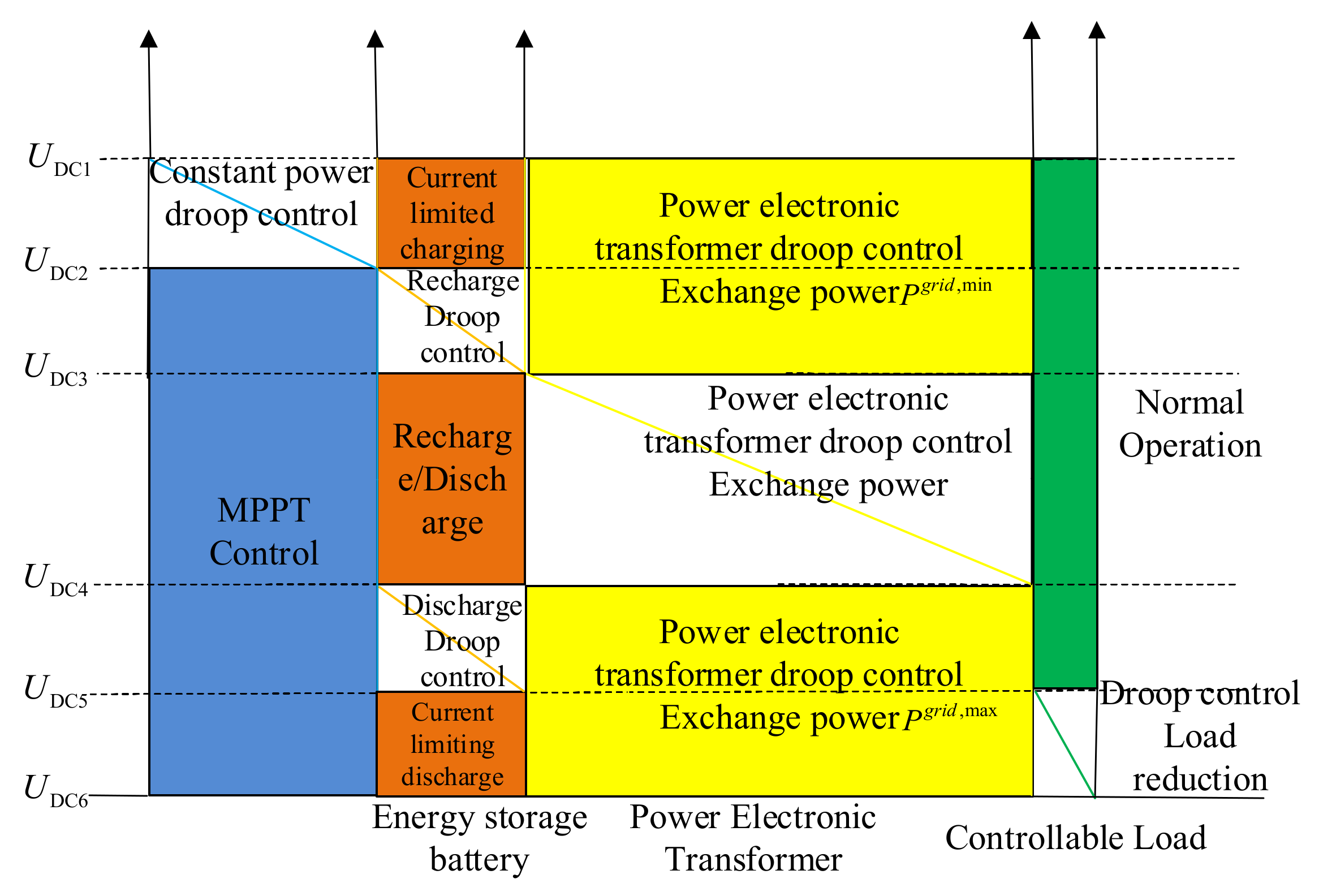
In the grid-connected operation of the DC microgrid, according to the operating state of the AC main network and the connected AC/DC hybrid system, the scheduling management calculates the active power of each scheduling resource in the DC microgrid through optimization calculation. Then, the power electronic transformer is adjusted by the bus control layer to control the DC bus voltage (, , and represents the upper and lower limits of the DC bus voltage in the DC microgrid, respectively), and according to the DC bus voltage, converters of each unit switch their operation control mode to realize the reasonable power distribution of each unit. The operating status of each unit under different control modes is shown in Table 1.
By setting the DC bus voltage to six critical values, the coordinated control strategy of the bus control layer can be divided into five working modes. Reference [9] introduces the allowable voltage range for the operation of medium-voltage and low-voltage microgrids. In this paper, six voltage critical values are set to divide different operating states. The designed operation control of the DC microgrid is shown in Figure 3.
4.2. AC Microgrid
The power electronic transformer can control the voltage and frequency of the AC-side low voltage actively and real-time through the voltage source converter and then realize the flexible adjustment of the voltage, current, and power of the AC microgrid. In the AC microgrid, photovoltaic, wind turbine, controllable load, and other units determine their active and reactive power by detecting the frequency and voltage of the AC bus.
In the grid-connected operation of the AC microgrid, according to the operating state of the AC main network and the connected AC/DC hybrid distribution network, the scheduling management can calculate the active power of each scheduling resource in the AC microgrid through optimization calculation. Then, the bus control layer can adjust to the power electronic transformer to control the AC bus frequency (, , and , respectively, representing the maximum and minimum voltage angular frequency of the AC side in the distributed network). In this paper, six frequency critical values are set to divide different operating states. The converter of each unit switches its operation control mode according to the frequency signal to realize the reasonable distribution of the active power. The operation control of the AC microgrid designed in this paper is shown in Figure 4.
5. Case Analysis
5.1. System Configuration
A calculation example based on the structure of the AC/DC hybrid distribution network shown in Figure 2 is analyzed. The curve of daily load comes from the data of bus load measured by a substation in December, as shown in Figure A1 from Appendix A. The parameters of distributed generation are shown in Table 2. Among them, the cost of each item is obtained through market research.
The optimal scheduling cycle usually ranges from 5–15 min, and it is set as 15 min in this paper. In each scheduling cycle, it is assumed that the load, distributed energy, and other power generation remain unchanged.
Because the wind capacity of distributed generation is small, it always works in the maximum power point tracking (MPPT). Therefore, only the photovoltaic, power storage, and reducible loads of DC side can be controlled through the power electronic transformers as shown in Figure 2. The voltage threshold is set as follows: , , , , , and , where is the rating bus voltage in the DC microgrid.
The power purchase price in the AC main network of the AC/DC hybrid distribution network is 0.67 RMB/kWh. Other parameters for thermal storage and load reduction in electricity storage and solar thermal systems are shown as Table 3.
In addition, the thermal conversion efficiency of solar collectors for generators and lithium bromide is 96% and 95%, respectively. The thermal conversion efficiency of thermal storage for generators and lithium bromide is 96% and 95%, respectively. Taking the lithium bromide absorption chillers as the basic part of the cooling load, the cooling load is set as 8% of the daily load curve in this paper.
The upper and lower limits of the exchanging power between the AC/DC hybrid distribution network and the AC main network are 2500 kW (the maximum power absorbed from the AC main network) and −500 kW (the maximum power that the AC/DC hybrid distribution network sends to the AC main network).
5.2. Case Solving
The optimal scheduling model of the AC/DC hybrid distribution network based on power electronic transformer is a mixed integer linear programming model with discrete variables. The example programming is based on MATLAB-YALMIP platform in this paper, and the open-source solver lpsolve is used to solve the model [20,21,22]. The solution flow chart is shown in Figure 5.
5.3. Result Analysis
The calculation result of the day-ahead scheduling is shown in Figure 6.
It can be seen from the results of the previous scheduling that wind power is always in the state of maximum power tracking, so it generates electricity as predicted. Since the distributed power generation in the AC/DC hybrid distribution network is sufficient at around 12:00, the AC/DC hybrid distribution network supplies power to the AC main network. However, at the same time, the exchanging power between the AC/DC hybrid distribution network and the AC main network is limited to avoid the influence of the output fluctuation of the distributed generation on the AC main network. From 11:45 to 13:15, the power electronic transformer controls the power storage to charge and absorb the output of the distributed generation to avoid the phenomenon of light abandonment. In order to prevent the AC main network from supplying power to the AC/DC hybrid network from exceeding the operating constraints, the power electronic transformer controls the power storage to discharge when the load is peak at 18:30–20:45 and the output of the distributed generation decreases. The exchanging power between the AC/DC hybrid network and the main AC network exceeds the maximum limit, and the power storage is discharged to keep the power storage consistent at the end and at the beginning of the scheduling cycle, ensuring that the power storage has the same control performance in the new scheduling cycle. In the simulation, the acceptable microgrid exchanging power of the AC main network fluctuates significantly (specifically reflected in the switching power limit), and the storage power has sufficient capacity. Thus, there is no wind or solar abandonment phenomenon during the entire scheduling cycle, and the complete consumption of renewable energy can be achieved. For the solar thermal systems, the light is insufficient at the beginning of the scheduling cycle. At the same time, due to the low operating cost of the solar thermal generator, priority is given to the operation of the solar thermal generator through the releasing of thermal storage. When the light is sufficient and the thermal collector absorbs a large amount of thermal, the thermal is stored for charging to ensure that the lithium bromide absorption chiller and the photothermal generator can work when the light is insufficient. Moreover, the lithium bromide absorption chiller uses the thermal of the collector after 18:30, and due to insufficient light, the thermal storage device releases thermal to maintain the photothermal generator and the lithium bromide absorption chiller.
After optimization scheduling, the total operating cost is 29,503 RMB, including power purchase cost 23,934 RMB, wind power cost 199.7 RMB, photovoltaic cost 5250.7 RMB, lithium bromide absorption chiller cost 17.3 RMB, solar thermal generator cost 11.8 RMB, and thermal storage cost 23.0 RMB.
If power electronic transformers are not used to connect the AC main network and the AC/DC hybrid distribution network, due to the dispersion of distributed power and reducible loads, the scheduling layer cannot control photovoltaic and wind power, including centralized photovoltaic power plants and wind farms. Therefore, photovoltaic and wind power always work in the state of MPPT, and the load power cannot be reduced. The storage power is charged and discharged according to the plan. This paper assumes that the power storage is charged at 11:00–14:00 and discharged at 19:00–22:00. It can be seen from Figure 7 that when there is no power electronic transformer to control the AC/DC hybrid distribution network and the storage is charged and discharged as planned, the exchanging power between the AC/DC hybrid distribution network and the AC main network is beyond the maximum at 18:30–22:00, and the maximum exchanging power is 2612.2 kW. At 12:00–14:00 below the minimum, the minimum exchanging power is −654.5 kW (the distributed system supplies 654.5 kW to the distribution network). If there is no power electronic transformer to control the AC/DC hybrid distribution network, the power exchange between the AC/DC hybrid distribution network and the AC main network will seriously exceed the limit and the AC/DC hybrid distribution network will not be able to focus on the advantage of the usage of renewable energy and reducing renewable energy penetration.
6. Conclusions
This paper studies the optimal scheduling strategy of AC/DC hybrid distribution network based on power electronic transformer.
(1) According to the topology characteristics and operation mode of the AC/DC hybrid distribution network based on power electronic transformer, a two-layer control structure including scheduling management layer and bus control layer is proposed, which can give full play to the “energy routing” function of power electronic transformer and realize the coordinated control of source, load, and storage in the system.
(2) The optimal scheduling strategy of the AC/DC hybrid distribution network takes the minimum operation cost of the AC/DC hybrid distribution network as the optimization objective, considering the energy characteristics of various distributed systems, the structure of AC/DC distributed network, and the interaction of “source–load–storage”. The feasibility of the optimal scheduling model is verified by the open-source solver, which can realize the complete absorption of renewable energy and the optimal coordinated control of “source–load–storage”.
(3) The proposed coordinated scheduling strategy provides a technical basis for the design, operation, and promotion of the AC/DC hybrid distribution network based on power electronic transformer.
Author Contributions
Conceptualization, L.Q. and Z.Y.; methodology, Q.P.; software, Q.P.; validation, B.T.; formal analysis, Q.P.; investigation, X.W.; resources, Y.C.; data curation, Y.C.; writing—original draft preparation, L.Q.; writing—review and editing, Y.C.; visualization, B.T.; supervision, Q.P.; project administration, L.Q.; funding acquisition, Z.Y. All authors have read and agreed to the published version of the manuscript.
Funding
This research was funded by National Key Research and Development Program 2017YFB0903204.
Institutional Review Board Statement
Not applicable.
Informed Consent Statement
Not applicable.
Data Availability Statement
Not applicable.
Acknowledgments
This work was supported by Supported by National Key Research and Development Program 2017YFB0903204.
Conflicts of Interest
The authors declare no conflict of interest.
Appendix A
The curve of daily load comes from the data of bus load measured by a substation in December, as shown in Figure A1.
Figure A1.
The curve of daily load comes from the data of bus load measured by a substation in December.
Figure A1.
The curve of daily load comes from the data of bus load measured by a substation in December.

References
- Baran, M.E.; Mahajan, N.R. DC distribution for industrial systems: Opportunities and challenges. IEEE Trans. Ind. Appl. 2003, 39, 1596–1601. [Google Scholar] [CrossRef]
- Riccobono, A.; Santi, E. Comprehensive review of stability criteria for DC power distribution systems. IEEE Trans. Ind. Appl. 2014, 50, 3525–3535. [Google Scholar] [CrossRef]
- Suryanarayana, H.; Sudhoff, S.D. Design paradigm for power electronics-based DC distribution systems. IEEE J. Emerg. Sel. Top. Power Electron. 2016, 5, 51–63. [Google Scholar] [CrossRef]
- Qu, L.; Yu, Z.; Song, Q.; Yuan, Z.; Zhao, B.; Yao, D.; Chen, J.; Liu, Y.; Zeng, R. Planning and analysis of the demonstration project of the MVDC distribution network in Zhuhai. Front. Energy 2019, 13, 120–130. [Google Scholar] [CrossRef]
- Liu, Y.; Chen, J.; Qu, L.; Yu, Z.; Nie, Z.; Zeng, R. Research on Access Mode of the Flexible DC Power Distribution System into AC System. Energies 2019, 12, 20. [Google Scholar]
- Kanchev, H.; Lu, D.; Colas, F.; Lazarov, V.; Francois, B. Energy Management and Operational Planning of a Microgrid with a PV-Based Active Generator for Smart Grid Applications. IEEE Trans. Ind. Electron. 2011, 58, 4583–4592. [Google Scholar] [CrossRef] [Green Version]
- Sechilariu, M.; Wang, B.; Locment, F. Building Integrated Photovoltaic System with Energy Storage and Smart Grid Communication. IEEE Trans. Ind. Electron. 2013, 60, 1607–1618. [Google Scholar] [CrossRef]
- Schonberger, J.; Duke, R.; Round, S.D. DC-Bus Signaling: A Distributed Control Strategy for a Hybrid Renewable Nano grid. IEEE Trans. Ind. Electron. 2006, 53, 1453–1460. [Google Scholar] [CrossRef]
- Sun, K.; Zhang, L.; Xing, Y.; Guerrero, J.M. A Distributed Control Strategy Based on DC Bus Signaling for Modular Photovoltaic Generation Systems with Battery Energy Storage. IEEE Trans. Power Electron. 2011, 26, 3032–3045. [Google Scholar] [CrossRef] [Green Version]
- Xiao, J.F.; Setyawan, L.; Wang, P.; Jin, C. Power-Capacity-Based Bus-Voltage Region Partition and Online Droop7, Coefficient Tuning for Real-Time Operation of DC Microgrids. IEEE Trans. Energy Convers. 2015, 30, 1338–1347. [Google Scholar] [CrossRef]
- Zhen, L.I.; Wanxing, S.; Qing, D. Coordinated control strategy of AC/DC hybrid power router based on voltage stabilization by energy storage. Autom. Electr. Power Syst. 2019, 43, 121–134. [Google Scholar]
- Li, Y.; Wang, L.; Huang, H.; Zhang, H. Coordinated Control Strategy for DC Bus of Energy Storage System without Communication Interconnection Line. Autom. Electr. Power Syst. 2018, 42, 118–124. [Google Scholar]
- Jin, C.; Wang, P.; Xiao, J.; Tang, Y.; Choo, F.H. Implementation of Hierarchical Control in DC Microgrids. IEEE Trans. Ind. Electron. 2014, 61, 4032–4042. [Google Scholar] [CrossRef]
- Xia, Y.; Yu, M.; Yang, P.; Peng, Y.; Wei, W. Generation-storage coordination for islanded DC microgrids dominated by PV generators. IEEE Trans. Energy Convers. 2018, 34, 130–138. [Google Scholar] [CrossRef]
- Gao, F.; Kang, R.; Cao, J.; Yang, T. Primary and Secondary Control in DC Microgrids: A Review. J. Mod. Power Syst. Clean Energy 2019, 7, 227–242. [Google Scholar] [CrossRef] [Green Version]
- Jiang, S.; Fan, C.; Huang, N.; Zhu, Y.; He, M. A Fault Location Method for DC Lines Connected With DAB Terminal in Power Electronic Transformer. IEEE Trans. Power Del. 2018, 34, 301–311. [Google Scholar] [CrossRef]
- Hooshmand, R.A.; Ataei, M.; Rezaei, M.H. Improving the Dynamic Performance of Distribution Electronic Power Transformers Using Sliding Mode Contro. J. Power Electron. 2012, 12, 145–156. [Google Scholar] [CrossRef] [Green Version]
- Briz, F.; Lopez, M.; Rodriguez, A.; Arias, M. Modular Power Electronic Transformers: Modular Multilevel Converter Versus Cascaded H-Bridge Solutions. IEEE Ind. Electron. Mag. 2016, 10, 6–19. [Google Scholar] [CrossRef]
- Xu, J.; Gao, C.; Ding, J.; Shi, X.; Feng, M.; Zhao, C.; Ding, H. High-speed Electromagnetic Transient (EMT) Equivalent Modelling of Power Electronic Transformer. IEEE Trans. Power Deliv. 2020, 36, 975–986. [Google Scholar] [CrossRef]
- Chen, X.; Wang, C.; Wu, Q.; Dong, X.; Yang, M.; He, S.; Liang, J. Optimal operation of integrated energy system considering dynamic heat-gas characteristics and uncertain wind power. Energy 2020, 198, 117270. [Google Scholar] [CrossRef]
- Chen, H.; Chen, S.; Li, M.; Chen, J. Optimal Operation of Integrated Energy System Based on Exergy Analysis and Adaptive Genetic Algorithm. IEEE Access 2020, 8, 158752–158764. [Google Scholar] [CrossRef]
- Li, P.; Wang, Z.; Wang, N.; Yang, W.; Li, M.; Zhou, X.; Yin, Y.; Wang, J.; Guo, T. Stochastic robust optimal operation of community integrated energy system based on integrated demand response. Int. J. Electr. Power Energy Syst. 2021, 128, 106735. [Google Scholar] [CrossRef]
Figure 1.
Topology of a typical three-port power electronic transformer.

Figure 2.
Topology of the AC/DC hybrid distribution network.

Figure 3.
Operation control diagram of DC microgrid.

Figure 4.
Operation control diagram of AC microgrid.

Figure 5.
Flow chart of optimal scheduling example.

Figure 6.
Optimal scheduling results of AC/DC hybrid distribution system. (a) Voltage of low-voltage DC side of power electronic transformer. (b) Predicted and actual wind power. (c) Predicted and actual PV power. (d) Charging and discharging power of energy storage. (e) SOC of power storage. (f) Photothermal system. (g) Exchange power between AC/DC hybrid distribution system and AC main network. (h) Load.

Figure 7.
Exchanging power between AC/DC hybrid distribution network and AC main network without power electronic transformer.
Figure 7.
Exchanging power between AC/DC hybrid distribution network and AC main network without power electronic transformer.


Table 1.
Control mode classification of DC microgrid.
| Control Mode | Distributed Power Converter | Storage Power Converter | Power Electronic Transformer | Reducible Load Converter |
|---|---|---|---|---|
| 1 | Droop control | Charging | Limit exchange power | Normal operation |
| 2 | MPPT | Charging under droop | Limit exchange power | Normal operation |
| 3 | MPPT | Charging/discharging | Droop control exchange power | Normal operation |
| 4 | MPPT | Charging under droop | Limit exchange power | Normal operation |
| 5 | MPPT | Discharging | Limit exchange power | Droop control |
Table 2.
Parameters of distributed generation.
| Type of Distributed Power | Capacity (kW) | Rated Power (kW) | Service Life (year) | Investment Cost (RMB/kWh) | Operation Cost (RMB/kWh) | Annual Utilization Hours (h) | Depreciation Rate (%) |
|---|---|---|---|---|---|---|---|
| Photovoltaic | 2000 | 1500 | 25 | 6,000,000 | 0.015 | 2000 | 8 |
| Wind power | 40 | 30 | 20 | 144,000 | 0.005 | 1800 | 8 |
| Storage | 500 | 400 | 15 | 1,502,500 | 0.0013 | 8760 | 8 |
| Solar collector | 100 | 80 | 20 | 320,000 | 0.017 | 6000 | 8 |
| Solar collector | 5 | 4 | 15 | 20,000 | 0.003 | 6000 | 8 |
| Lithium absorption chiller | 10 | 8 | 20 | 60,000 | 0.001 | 6000 | 8 |
| Thermal storage | 20 | 16 | 20 | 100,000 | 0.001 | 8760 | 8 |
Table 3.
Other system parameters.
| Storage power | Total battery limit: 500 kWh Charging/discharging efficiency: 93.81% Power storage SOC: 5–95% Initial power storage: 50 kWh Maximum number of charging and discharging in the scheduling period: 1.5 times |
| Thermal storage | Total calories: 200 kWh Thermal storage SOC: 5–95% Thermal charging/discharging efficiency: 95% Thermal dissipation coefficient: 0.6% |
| Reducible Load | Unit compensation: 1.1 RMB/kWh Maximum power reduction: 200 kW Maximum sustainable time: 2 h Minimum duration: 0.5 h Reducible time: 18:00–23:00 Limit of reducible times: 2 times |
| Photothermal system | Ascent rate limit: 10 kW/h Downhill rate limit: −10 kW/h Maximum number of starts and stops: 4 times Minimum continuous running time: 3 h |
Publisher’s Note: MDPI stays neutral with regard to jurisdictional claims in published maps and institutional affiliations. |
© 2021 by the authors. Licensee MDPI, Basel, Switzerland. This article is an open access article distributed under the terms and conditions of the Creative Commons Attribution (CC BY) license (https://creativecommons.org/licenses/by/4.0/).
Share and Cite
MDPI and ACS Style
Peng, Q.; Qu, L.; Yuan, Z.; Wang, X.; Chen, Y.; Tian, B. Optimal Scheduling Strategy of AC/DC Hybrid Distribution Network Based on Power Electronic Transformer. Energies 2021, 14, 3219. https://doi.org/10.3390/en14113219
AMA Style
Peng Q, Qu L, Yuan Z, Wang X, Chen Y, Tian B. Optimal Scheduling Strategy of AC/DC Hybrid Distribution Network Based on Power Electronic Transformer. Energies. 2021; 14(11):3219. https://doi.org/10.3390/en14113219
Chicago/Turabian StylePeng, Qingwen, Lu Qu, Zhichang Yuan, Xiaorui Wang, Yukun Chen, and Baoye Tian. 2021. "Optimal Scheduling Strategy of AC/DC Hybrid Distribution Network Based on Power Electronic Transformer" Energies 14, no. 11: 3219. https://doi.org/10.3390/en14113219
Note that from the first issue of 2016, this journal uses article numbers instead of page numbers. See further details here.