
Degradation-Conscious Equivalent Consumption Minimization Strategy for a Fuel Cell Hybrid System


1
School of Mechanical Engineering, Pusan National University, Busan 46241, Korea
2
Maritime Technology Research Institute, Agency of Defense Development, Changwon-si 51698, Korea
3
Department of Naval Architecture and Ocean Engineering, Pusan National University, Busan 46241, Korea
*
Author to whom correspondence should be addressed.
Energies 2021, 14(13), 3810; https://doi.org/10.3390/en14133810
Submission received: 25 May 2021
/
Revised: 17 June 2021
/
Accepted: 22 June 2021
/
Published: 24 June 2021
(This article belongs to the Topic Power System Modeling and Control)
Abstract
:The design of an energy management strategy is critical to improving the fuel efficiency of a vehicle system with an alternative powertrain system, such as hybrid electric vehicles or fuel cell electric vehicles. In particular, in fuel cell electric vehicles, the energy management strategy should consider system degradation and fuel savings because the hardware cost of the fuel cell system is much higher than that of a conventional powertrain system. In this paper, an easily implantable near-optimal energy management controller is proposed. The proposed controller distributes power generation between the fuel cell and the battery to simultaneously minimize system degradation and fuel usage. The controller is designed to consider the degradation cost and fuel cost in the framework of the equivalent consumption minimization strategy concept. The proposed controller was validated with a fuel cell electric vehicle model in MATLAB/Simulink (MathWorks, Natick, MA, USA). The proposed control strategy showed significant overall cost reduction compared to a thermostat control strategy and a conventional Equivalent Consumption Minimization Strategy (ECMS) strategy.
1. Introduction
In all industries, including the power and automobile industry, both the government and private companies strive to develop innovative technologies for new alternative energy and powertrain systems. At the same time, strict emission regulations are being proposed. As the regulations on automobile exhaust gas and fuel economy improvement become more stringent [1], electric and hybrid vehicles are becoming more attractive as alternatives to tackle energy shortages and environmental problems.
A hybrid vehicle is driven by power from at least two energy sources. A typical hybrid vehicle uses an internal combustion engine or fuel cell system as the main power source and batteries or capacitors as an auxiliary power source. Among the diverse energy sources used in hybrid vehicles, fuel cells are some of the most promising power systems because they have a larger energy density and a higher energy efficiency than other power sources. Some researchers report that the “fuel economy of hydrogen fuel cell vehicles is projected to be 2.5–2.7 times the fuel economy of the conventional gasoline internal combustion engine vehicles on the same platforms” [2].
A fuel cell system (FSC) is capable of supplying the demanded power under steady-state operating conditions. However, the performance of FSCs could be significantly degraded when the power output severely changes [3]. Furthermore, FSCs in a vehicle are not designed to meet the rare but high peak-power demands. For this reason, an ultra-capacitor or rechargeable battery (such as a NiMH, lithium–ion polymer, or lithium–ion battery, etc.) is commonly used as an auxiliary power source in parallel with a fuel cell system.
There are basically two major topics in a hybrid electric vehicle in terms of control. One is energy management for optimizing fuel efficiency and emission, and the other is drivability control for optimizing drivability, comfort, and safety [4]. A hybrid vehicle’s energy management control plays an important role in determining the power distribution between two energy sources according to the required power. This is very important as it directly influences the fuel economy and lifetime improvement of the hybrid vehicle [4,5,6,7].
The energy management control can be classified into rule-based control strategies and optimization-based control strategies [8,9]. Recently, learning-based energy management system (EMS) control methods, such as deep reinforcement learning and fuzzy Q-learning, have been studied [10]. Rule-based control is simple to apply by distributing the power between the main and auxiliary power sources according to deterministic conditions such as the battery State of Charge (SOC) or vehicle driving conditions. The powertrain of the hybrid vehicle is controlled based on a rule that is designed using heuristics or intuition.
Many studies on rule-based control for a hybrid vehicle have been popular because of the simple and easily implementable control structure. For example, two rule-based control strategies are battery SOC control and engine operating point control, and their effects on the fuel economy were investigated for two hybrid powertrain configurations (power split and mode switching) [11]. In addition, EMS of a fuel cell/battery hybrid vehicle was investigated based on the target value of the battery SOC to optimize the energy efficiency and extend the lifetime of the system [12]; however, these controllers could not address the optimal performance due to the design methodologies, such as control parameter tuning based on heuristics and intuition.
Several EMSs for optimization-based control strategies have been presented in the technical literature. An optimization-based energy control strategy is based on optimization theory and presents noticeable fuel-saving performance while allowing real-time control [9]. Dynamic programming (DP) is classified as a global optimization method that can find optimal solutions [13,14]. DP and simulated annealing were investigated and compared in terms of fuel consumption and emission performance while considering battery SOC [13]. However, most optimization-based energy control strategies have a huge drawback of causality if the optimization is formulated as a global optimization problem.
An equivalent consumption minimization strategy (ECMS) is one of the optimal controllers that avoids the causality issue but at the cost of loss of optimality. Various types of controllers based on the ECMS concept are studied and applied to hybrid vehicles [6,15]. An ECMS controller is classified as a real-time optimal controller based on instantaneous optimization. ECMS determines the optimal power distribution between the main power source and the auxiliary power source in every time step by transforming all the power into a fuel rate. For example, battery power flow is transformed into a virtual fuel rate using an equivalent coefficient in a hybrid vehicle with an internal combustion (IC) engine and a battery. Thus, the ECMS can determine the best power distribution that minimizes the sum of the fuel rate of the engine and the virtual fuel rate of the battery.
Similar approaches are valid for different system architectures and types of machines involved [16]. An ECMS approach for a flex-fuel hybrid powertrain composed of an IC engine/battery was investigated in [8]. In order to optimize the vehicle’s electrical system, which is composed of a battery and alternator, ECMS was applied and compared to a rule-based control strategy (voltage regulation) [17]. ECMS can improve the fuel economy by about 3.6% compared to a rule-based strategy for a parallel plug-in hybrid vehicle with a transmission-mounted electric device [18].
The actual measured fuel consumption obtained from an EMS strategy implemented in a Toyota Prius was analyzed and compared with the ECMS simulation results [19]. ECMS can reduce fuel consumption by up to 8.5% compared to rule-based control, which considers engine operating conditions based on different SOCs and required torque output [20]. ECMS is better at regulating the SOC of the battery at the end of the driving cycle and improves fuel economy by 1.88% compared to a rule-based method [21].
One of the drawbacks of ECMS is that the objective of the controller is formulated only for fuel savings because its basic concept is minimizing the equivalent fuel, which consists of the real fuel and the virtual fuel transformed from the consumed electric energy; therefore, a conventional ECMS cannot address other control objectives, such as emissions or system degradations. In fuel cell vehicles, the longevity of a fuel cell system is an important factor for both manufacturers and consumers because the hardware cost of the fuel cell system makes up a large part of the total vehicle cost [22].
Even though the ECMS approach has been extensively studied for hybrid vehicles, there are only a few studies on ECMS considering the degradation cost of a fuel cell and battery for a fuel cell/battery hybrid vehicle. In this paper, we propose a degradation-conscious ECMS (D-ECMS). The proposed method converts the fuel usage, electric energy consumption, and degradations of the fuel cell system into financial costs. The proposed EMS algorithm was validated through a series of simulations.
2. Fuel Cell/Battery Hybrid System Modeling
2.1. System Configuration
Figure 1 shows a fuel cell/battery energy system diagram, including the power flow and system structure. The solid lines represent the power flows, and dashed lines indicate the signal flows for controlling energy flow. The inputs are the FC current/voltage and traction voltage, from which the tuning variables are computed and fed into the DC/DC converter in order to determine the power distribution. The fuel cell output is directly controlled by the reference current, which is deduced from the EMS. The studied vehicle in this paper is a two-seater city car. It is a commercial Tazzari Zero (Tazzari, Imola, Italy) electric vehicle equipped with a single ratio gearbox, a differential, and two driven wheels. The vehicle model used to implement the EMS was obtained from the literature [23].
2.2. Fuel Cell System Model
The fuel cell system consists of a fuel cell stack, smoothing inductor, and boost chopper (DC/DC converter) [23,24]. The type of fuel cell is a polymer exchange membrane fuel cell with a capacity of 16 kW, and its maximum current reaches up to 400 A. A compressor ensures the supply of oxygen, and a high-pressure hydrogen tank stores hydrogen at 350 bar. The corresponding system parameters are shown in Table 1. Typically, the characteristics of a fuel cell are expressed by a polarization curve representing the voltage variation in the current changes. As shown in Figure 2a, the voltage () decreases as the current () increases because of the activation, ohmic, and concentration losses of the fuel cell stack. The hydrogen mass flow rate can be expressed as an affine function of the current flow, as shown in Figure 2b.
The smoothing inductor was modeled with first-order dynamics as follows:
where is the current output from the fuel cell, is the fuel cell voltage, and is the output voltage from the fuel cell system. The DC–DC converter was modeled as a static model with a variable modulation ratio () as follows:
where is the output voltage from the fuel cell system, is the battery voltage, and is the current output from the fuel cell system.
2.3. Battery Model
2.4. Driving Load Model
For simulation, assuming no tire slipping (wheel speed and vehicle speed are the same), the driving load or required driving force () can be calculated as follows:
where is the vehicle speed. is the equivalent mass of the powertrain inertia. The vehicle mass is 877.8 kg, including two passengers. The corresponding parameters and their values are listed in Table 3.
2.5. Traction System Model
The traction system has a 15 kW induction motor driven by a voltage source inverter connected to a DC–DC converter. The required motor speed () and motor torque () can be calculated as follows:
where is the tire radius and is the motor efficiency. The motor efficiency is a function of vehicle speed and transmission force, as shown in Figure 4. The corresponding motor current () can be calculated from the required driving force as follows:
3. Energy Management Strategy
3.1. Rule-Based Strategy
Thermostat control is one of the most popular rule-based strategies. The following control strategy is used as a baseline controller.
The fuel cell system is simply operated based on previously defined upper/lower limits of the SOC. As the battery SOC reaches the lower limit, the fuel cell is turned on and supplies power to the system; when the fuel cell is turned off, only the battery supplies the power for propulsion.
3.2. The Equivalent Consumption Minimization Strategy (ECMS)
The main concept of the ECMS is to equate the battery power consumption to fuel consumption and then find the optimal operating point where the sum of the actual fuel consumption and the equivalent battery fuel consumption becomes the minimum. The equivalent battery fuel consumption (g/s) can be formulated as below:
where is the battery power (watts), is the average specific consumption of the fuel cell (g/W·s), and is the total electrical system efficiency, including the converter and battery. The total equivalent fuel consumption is defined as shown below.
In order to make the hybrid vehicle operate in the charge-sustaining mode for the entire driving cycle, a penalty function is multiplied by the battery equivalent fuel consumption. The penalty function is calculated with the battery SOC (in percentage) and is defined as below:
The variation of the penalty factor with SOC is shown in Figure 5 for and .
Figure 6 illustrates the discrete situations of ECMS at a power demand of 6 kW and 60% SOC. The plot of is linear since the battery power decreases as the fuel cell power increases. Furthermore, the battery power becomes zero when the fuel cell power is equal to the power demand. The red dot in the bottom plot of Figure 6 indicates the optimal fuel cell power.
3.3. Degradation-Conscious Equivalent Consumption Minimization Strategy (D-ECMS)
The degradation of a fuel cell and battery is regarded as a major problem for hybrid vehicles; however, most existing energy management strategies only focus on fuel economy. In this paper, we propose D-ECMS, which minimizes both fuel consumption and degradation simultaneously. Fuel cell degradation over time is affected by the change in the output of the fuel cell, which is expressed by the following equation [23,28,29]:
where and are load coefficients, and is the rated power of the fuel cell. Battery degradation is a function of both its SOC and power transient, which is as follows: [24]:
where is a weighting function to penalize the battery degradation due to too much use of SOC, and is a weighting function to penalize the battery degradation due to too much power transient:
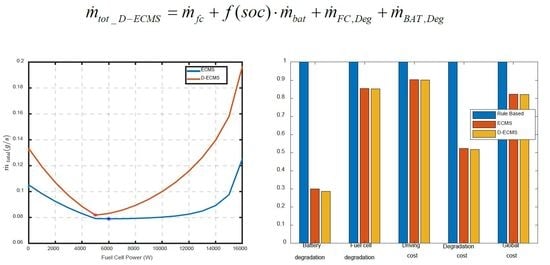
The equivalent degradation cost of the fuel cell and the battery is transformed into fuel consumption defined by the following equations.
The costs of hydrogen production, a fuel cell power system for a transportation application and a battery pack are [30], [31], and (USD 200 $/kWh in 2020) [32], respectively. The total equivalent consumption applying the degradation cost of a fuel cell/battery is calculated by Equation (19).
Figure 7 shows an illustration of the ECMS and D-ECMS operation at a power demand of 6 kW and 60% SOC.
4. Simulation and Results
We compared the effect of three energy management strategies: a rule-based strategy (RB), ECMS, and D-ECMS. In order to compare the effect on the fuel economy and cost savings, the models were implemented in Matlab/Simulink. Each energy management strategy was implemented in EMS blocks, as shown in Figure 1. Figure 8 shows the structure of the energy management strategy applied in MATLAB/Simulink.
The power demand and the battery SOC are inputs to the EMS algorithm. A low-pass filter was used in order to prevent a drastic load fluctuation of the fuel cell as follows:
where is the target power, is the time constant of the low-pass filter, and is the output from the EMS algorithm. Because the fuel cell voltage is a function of the fuel cell current, as shown in Figure 2a, the required fuel cell current can be algebraically determined from the target power.
Vehicle simulations were conducted with the FTP-72 driving cycle. Simulation results with RB are given in Figure 9. The initial battery SOC was set as 0.7, SOCL was 0.4, and SOCH was 0.7. The fuel cell was turned off until the battery SOC reached the lower limit, while only the battery supplied power in response to the required power. As the battery SOC reached the lower limit of 0.4, the fuel cell was turned on and operated under constant reference input current. It supplied power and charged the battery simultaneously, as shown in the second plot in Figure 9.
Figure 10 and Figure 11 show the vehicle simulation results obtained from ECMS and D-ECMS, respectively. The top plots in each figure represent the reference and actual vehicle velocity, and the second plots in each figure are for power variation of the bus, fuel cell, and battery with time. Voltage variation of the fuel cell and battery is shown in the last plots in Figure 10 and Figure 11. As shown in the second plots in Figure 10 and Figure 11, the fuel cell operates in response to the required power, and the battery is operated under charge-sustaining mode.
Table 4 shows a comparison of the three energy management strategies. In order to validate the distinct features of each EMS, the battery/fuel cell degradation formula and cost were used with the simulation results. Battery degradation is a function of the SOC and power transients [23], and fuel cell degradation depends on the fuel cell power operation and start/stop cycles [28,29]. The degradation cost of a fuel cell and battery is given in Equations (22) and (23), respectively.
The cost of hydrogen consumption is calculated from Equation (23). In addition, a battery recharging cost is computed by simulating the fuel cell system running for charging the battery to the initial SOC. The cost of energy for driving, , is defined as a sum of hydrogen energy cost and battery energy cost consumed during driving and shown in Equation (24). Equation (25) shows the degradation cost consisting of the fuel cell degradation cost and the battery degradation cost. The overall cost (the global cost function) is defined in Equation (26). All costs are calculated after vehicle simulation with the FTP-72 driving cycle.
The vehicle simulation results for ECMS and D-ECMS show better performance than those obtained from RB except for hydrogen consumption, as shown in Table 4. The RB case consumed less hydrogen because it consumed more battery SOC than ECMS and D-ECMS. The driving range of each strategy can be indirectly compared using the driving cost. A lower driving cost means a longer driving range. The driving range of ECMS and D-ECMS would be 1.91 and 1.93 times longer than that of RB, respectively. For degradation, ECMS reduced the system degradation by 91% compared to RB and D-ECMS reduced the system degradation by 93%.
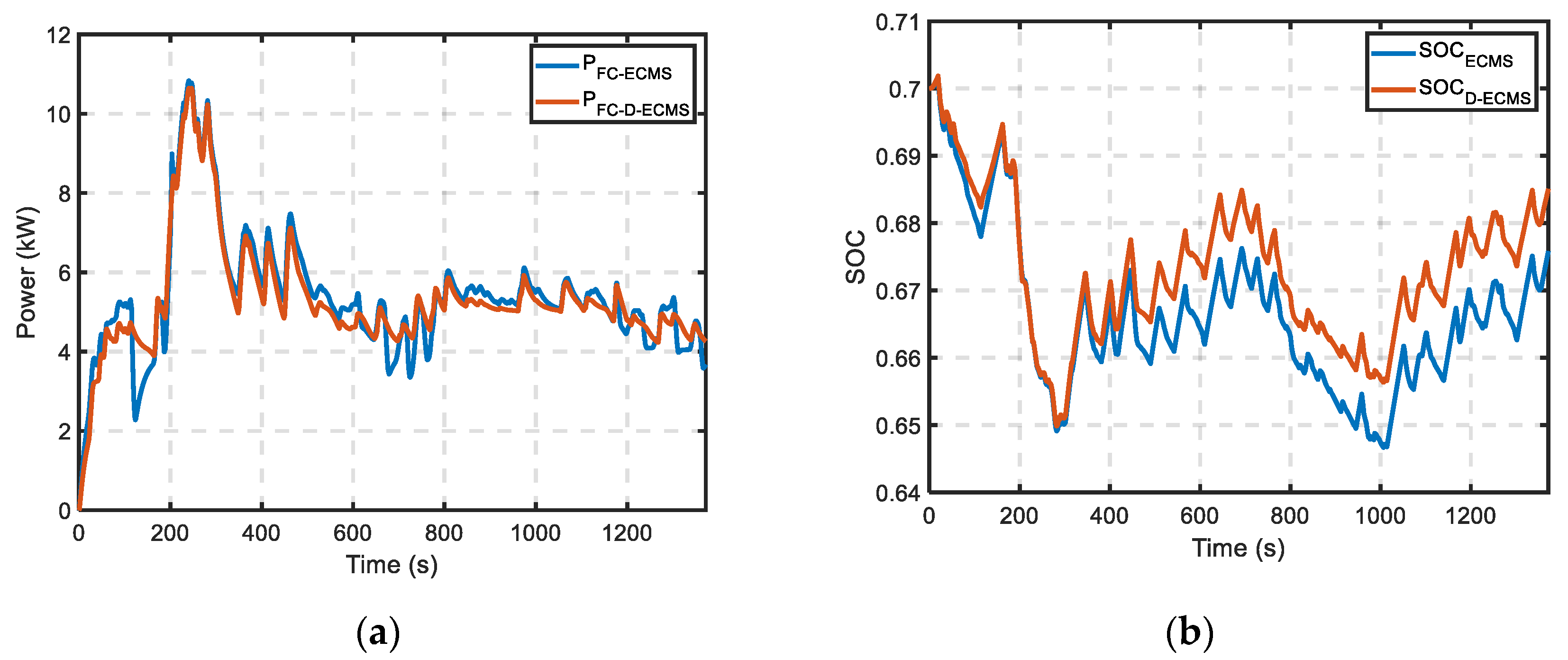
The global cost is lower by about 21.95% and 0.35% compared to the RB and ECMS due to the degradation of the fuel cell/battery. The improvement in degradation performance can be explained by observing the fuel cell power and SOC variations, as shown in Figure 12. The D-ECMS case shows less fluctuating power and SOC profiles than the ECMS case because D-ECMS explicitly considers the degradation in the controller design.
5. Conclusions
An energy management strategy is an important topic for a fuel cell hybrid vehicle. In this paper, we proposed D-ECMS, which reflects the energy-source degradation cost along with fuel economy. In order to validate the effect of the proposed EMS on the fuel economy and cost performance, RB and conventional ECMS were compared for the FTP-72 driving cycle. The vehicle simulation results showed that both ECMS and D-ECMS could maintain the SOC of the battery at the end of the driving process. Even though hydrogen consumption is higher than that of RB and ECMS, D-ECMS showed improvements of about 4.77% and 0.17% in battery and FC degradation, respectively. This happened because D-ECMS minimizes the fluctuation of the battery and FC output power, which affects the degradation, and it considers fuel consumption. Consequently, D-ECMS improves the global cost by 34.43% and 1.01% compared to the RB and ECMS, respectively.
Author Contributions
Conceptualization, C.A.; methodology, C.A.; formal analysis, L.K.; investigation, L.K. and C.A.; resources, L.K. and C.A.; data curation, L.K.; writing—original draft preparation, L.K.; writing—review and editing, C.A. and D.-S.C.; visualization, L.K.; supervision, C.A.; project administration, D.-S.C.; funding acquisition, D.-S.C. All authors have read and agreed to the published version of the manuscript.
Funding
This work was supported by the National Research Foundation of Korea (NRF) grant funded by the Korean government (MSIP) through GCRC-SOP (No. 2011-0030013).
Institutional Review Board Statement
Not applicable.
Informed Consent Statement
Not applicable.
Conflicts of Interest
The authors declare no conflict of interest.
References
- Xin, Q.; Pinzon, C.F. Improving the environmental performance of heavy-duty vehicles and engines: Particular technologies. In Alternative Fuels and Advanced Vehicle Technologies for Improved Environmental Performance, 1st ed.; Folkson, R., Ed.; Elsevier: Amsterdam, The Netherlands, 2014; pp. 279–369. [Google Scholar] [CrossRef]
- Ahluwalia, R.K.; Wang, X.; Rousseau, A.; Kumar, R. Fuel economy of hydrogen fuel cell vehicles. J. Power Sources 2004, 130, 192–201. [Google Scholar] [CrossRef]
- Fletcher, T.; Thring, R.; Watkinson, M. An Energy Management Strategy to concurrently optimize fuel consumption & PEM fuel cell lifetime in a hybrid vehicle. Int. J. Hydrogen Energy 2016, 41, 21503–21515. [Google Scholar] [CrossRef] [Green Version]
- Chan, C.C. The State of the Art of electric, Hybrid, and Fuel Cell Vehicles. Proc. IEEE 2007, 95, 704–718. [Google Scholar] [CrossRef]
- Xu, L.F.; Li, J.Q.; Hua, J.F.; Li, X.J.; Ouyang, M.G. Optimal vehicle control strategy of a fuel cell/battery hybrid city bus. Int. J. Hydrogen Energy 2009, 34, 7323–7333. [Google Scholar] [CrossRef]
- Paganelli, G.; Guezennec, Y.; Rizzoni, G. Optimizing Control Strategy for Hybrid Fuel Cell Vehicle. In Proceedings of the SAE 2002 World Congress, Detroit, MI, USA, 4–7 March 2002. [Google Scholar] [CrossRef]
- Sciarretta, A.; Guzzelle, L. Control of hybrid electric vehicles. IEEE Control Syst. Mag. 2007, 27, 60–70. [Google Scholar] [CrossRef]
- Manzie, C.; Grondin, O.V.; Sciarretta, A.; Zito, G. ECMS Controller Robustness in Flex-Fuel Hybrid Vehicles. J. Dyn. Syst. Meas. Control 2014, 136, 064504. [Google Scholar] [CrossRef]
- Panday, A.; Bansal, H.O. A Review of Optimal Energy Management Strategies for Hybrid Electric Vehicle. Int. J. Veh. Tech. 2014, 2014. [Google Scholar] [CrossRef] [Green Version]
- Hu, Y.; Li, W.M.; Xu, K.; Zahid, T.M.; Qin, F.Y.; Li, C.M. Energy Management Strategy for a Hybrid Electric Vehicle Based on Deep Reinforcement Learning. Appl. Sci. 2018, 8, 187. [Google Scholar] [CrossRef] [Green Version]
- Wu, J.D.; Peng, J.K.; He, H.W.; Luo, J.Y. Comparative analysis on the rule-based control strategy of two typical hybrid electric vehicle powertrain. Energy Proc. 2016, 104, 384–389. [Google Scholar] [CrossRef]
- Zhao, Y.; Song, H.; Liu, Y.; Yu, Z. Energy Management of Dual Energy Source of Hydrogen Fuel Cell Hybrid Electric Vehicles. SAE Tech. Paper 2020. [Google Scholar] [CrossRef]
- Delprat, S.; Lauber, J.M.; Guerra, T.M.; Rimaux, J. Control of a Parallel Hybrid Powertrain Optimal Control. IEEE Trans. Veh. Technol. 2004, 53, 872–881. [Google Scholar] [CrossRef]
- Lin, C.C.; Peng, H.; Grizzle, J.W.; Kang, J.M. Power Management Strategy for a Parallel Hybrid Electric Truck. IEEE Trans. Contr. Syst. Technol. 2003, 11, 839–849. [Google Scholar] [CrossRef] [Green Version]
- Paganelli, G.; Delprat, S.; Guerra, T.M.; Rimaux, J.; Santin, J.J. Equivalent Consumption Minimization Strategy for Parallel Hybrid Powertrains. In Proceedings of the 55th IEEE Vehicular Technology Conference, Birmingham, AL, USA, 6–9 May 2002; pp. 2076–2081. [Google Scholar] [CrossRef]
- Sciarretta, A.; Back, M.; Guzzella, L. Optimal Control of Parallel Hybrid Electric Vehicles. IEEE Trans. Contr. Syst. Technol. 2004, 12, 352–363. [Google Scholar] [CrossRef]
- Couch, J.; Fiorentini, L.S.; Canova, M. An ECMS-Based Approach for the Energy Management of a Vehicle Electrical System. IFAC Proc. Vol. 2013, 46, 115–120. [Google Scholar] [CrossRef]
- Kang, K.; Sim, K.; Hwang, S.H. Equivalent consumption minimization strategy for parallel plug-in hybrid vehicle. In Proceedings of the KSME Conference, Jeju, Korea, 12–15 July 2017. [Google Scholar]
- Hofman, T.; Purnot, T. A Comparative Study and Analysis of an Optimized Control Strategy for the Toyota Hybrid System. World Electr. Veh. J. 2009, 3, 563–571. [Google Scholar] [CrossRef] [Green Version]
- Hwang, H.Y. Developing Equivalent Consumption Minimization Strategy for Advanced Hybrid System-II Electric Vehicles. Energies 2020, 13, 2033. [Google Scholar] [CrossRef]
- Liu, X.; Qin, D.; Wang, S.Q. Minimum Energy Management Strategy of Equivalent Fuel Consumption of Hybrid Electric Vehicle Based on Improved Global Optimization Equivalent Factor. Energies 2019, 12, 2076. [Google Scholar] [CrossRef] [Green Version]
- Thompson, S.T.; James, B.D.; Huya-Kouadio, J.M.; Houchins, C.; DeSantis, D.A.; Ahluwalia, R.; Wilson, A.R.; Kleen, G.; Papageorgopoulos, D. Direct hydrogen fuel cell electric vehicle cost analysis: System and high-volume manufacturing description, validation, and outlook. J. Power Sources 2018, 399, 304–313. [Google Scholar] [CrossRef]
- Départure, C.M.; Jemeï, S.M.; Boulon, L.; Bouscayrol, A.; Marx, N.G.; Morando, S.M.; Castaings, A. IEEE VTS Motor Vehicles Challenge 2017—Energy Management of a Fuel Cell/Battery Vehicle. In Proceedings of the 2016 IEEE Vehicle Power and Propulsion Conference (VPPC), Hangzhou, China, 17–20 October 2016; pp. 1–6. [Google Scholar] [CrossRef]
- Delarue, P.; Bouscayrol, A.; Semail, E. Generic control method of multileg voltage-source-converters for fast practical implementation. IEEE Trans. Power Electron. 2003, 18, 517–526. [Google Scholar] [CrossRef]
- Liaw, B.Y.; Nagasubramanian, G.; Jungst, R.G.; Doughty, D.H. Modeling of lithium ion cells—A simple equivalent-circuit model approach. Solid State Ion. 2004, 175, 835–839. [Google Scholar] [CrossRef]
- Dubarry, M.; Vuillaume, N.; Liaw, B.Y. From single cell model to battery pack simulation for Li-ion batteries. J. Power Sources 2009, 186, 500–507. [Google Scholar] [CrossRef]
- Chiang, Y.H.; Sean, W.Y.; Ke, J.C. Online estimation of internal resistance and open-circuit voltage of lithium-ion batteries in electric vehicles. J. Power Sources 2011, 196, 3921–3932. [Google Scholar] [CrossRef]
- Herr, N.; Nicod, J.-M.; Varnier, C.; Jardin, L.; Sorrentino, A.; Gouriveau, R.; Hissel, D.; Péra, M.-C. Decision process to manage useful life of multi-stacks fuel cell systems under service constraint. Renew. Energ 2017, 105, 590–600. [Google Scholar] [CrossRef] [Green Version]
- Chen, H.; Pei, P.; Song, M. Lifetime prediction and the economic lifetime of Proton Exchange Membrane fuel cells. Appl. Energy 2015, 142, 154–163. [Google Scholar] [CrossRef]
- USDRIVE. Hydrogen Production Tech Team Roadmap. 2017. Available online: https://www.energy.gov/eere/vehicles/downloads/us-drive-hydrogen-production-technical-team-roadmap (accessed on 24 June 2021).
- USDRIVE. Fuel Cell Technical Team Roadmap. 2017. Available online: https://www.energy.gov/eere/vehicles/downloads/us-drive-fuel-cell-technical-team-roadmap (accessed on 24 June 2021).
- Nykvist, B.; Nilsson, M. Rapidly falling cost of battery packs for electric vehicles. Nat. Clim. Chang. 2015, 5, 329–332. [Google Scholar] [CrossRef]
Figure 1.
Diagram of fuel cell/battery energy system.

Figure 2.
Characteristic of the fuel cell: (a) fuel cell polarization curve; (b) hydrogen consumption rate with current change.
Figure 2.
Characteristic of the fuel cell: (a) fuel cell polarization curve; (b) hydrogen consumption rate with current change.
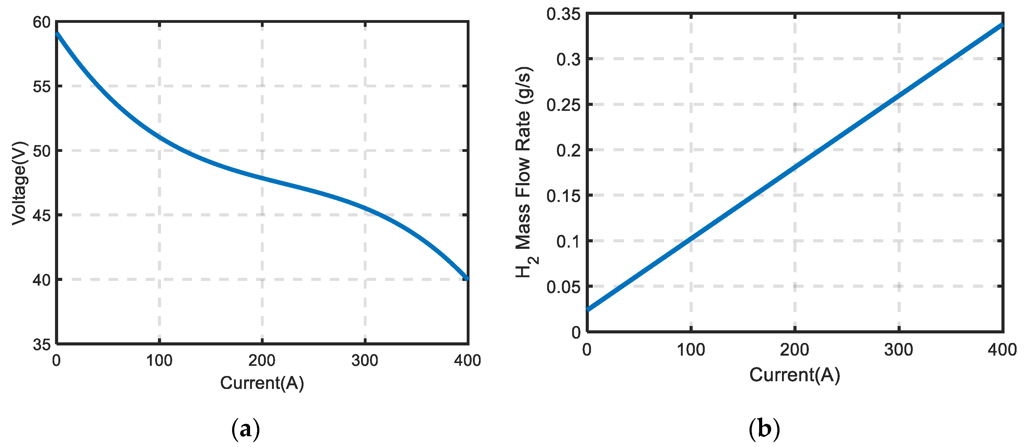
Figure 3.
Equivalent circuit model of battery.
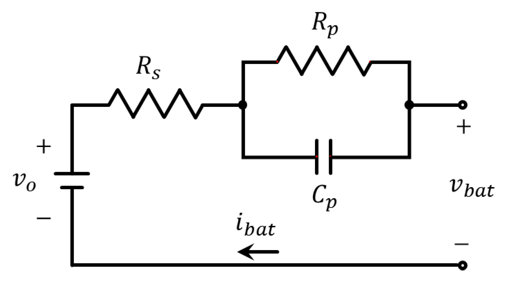
Figure 4.
Motor efficiency map.
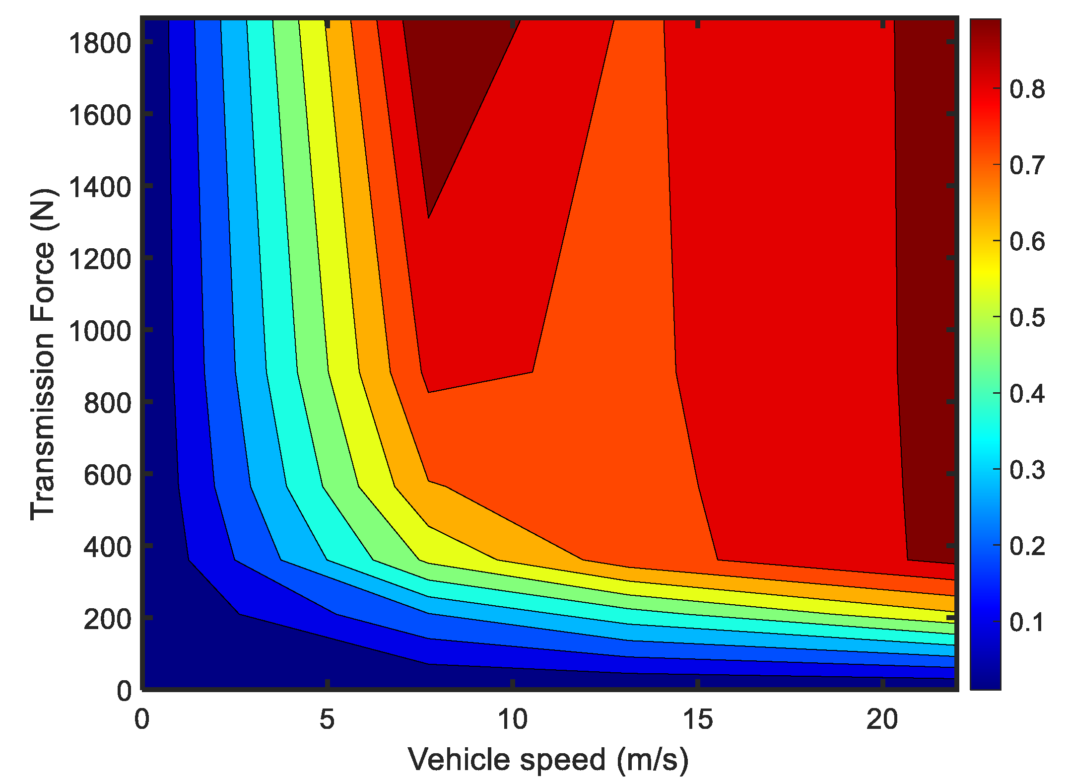
Figure 5.
The variation of the penalty factor with SOC.
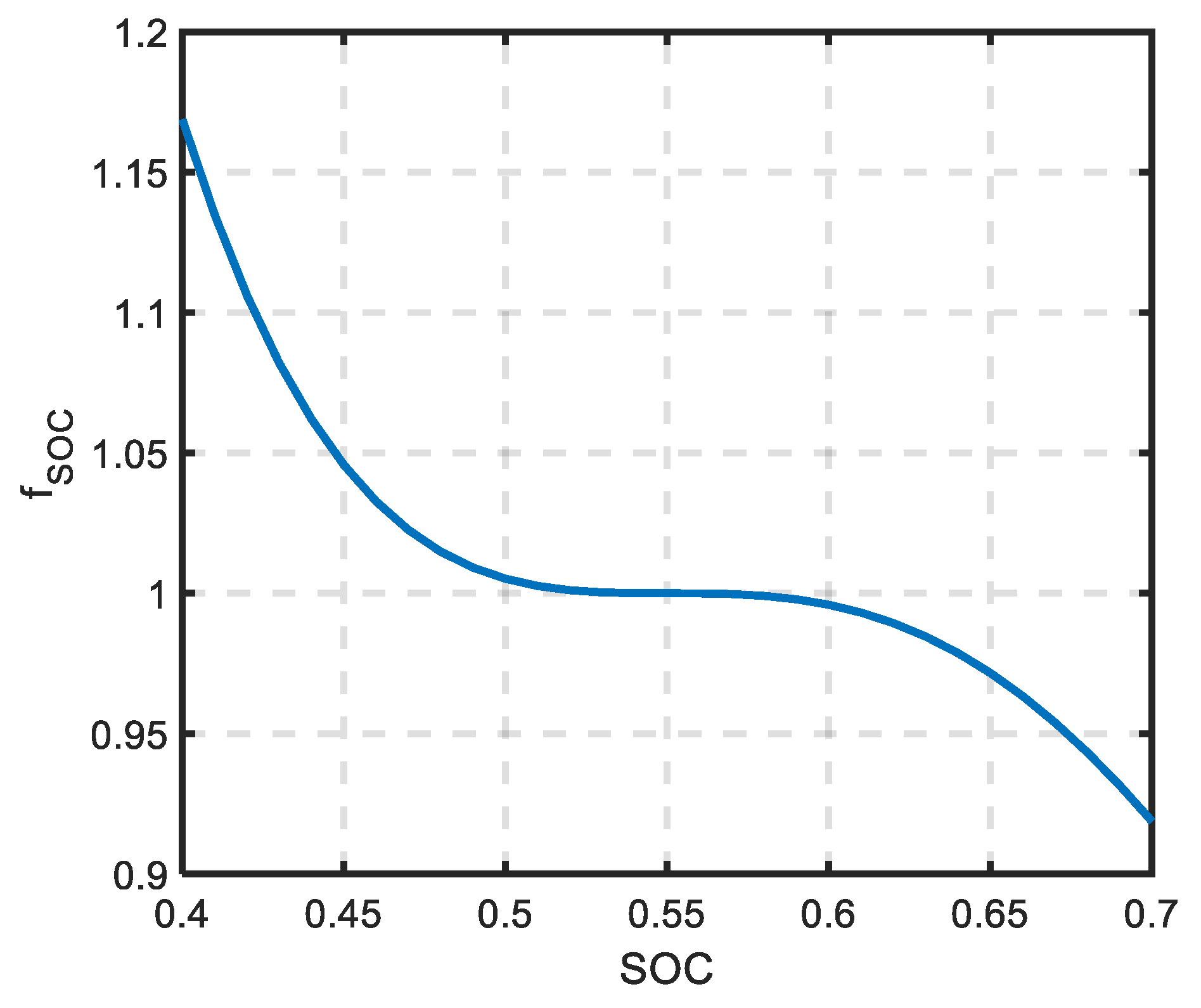
Figure 6.
Illustration of the algorithm operation at power demand of 6 kW and 60% SOC.
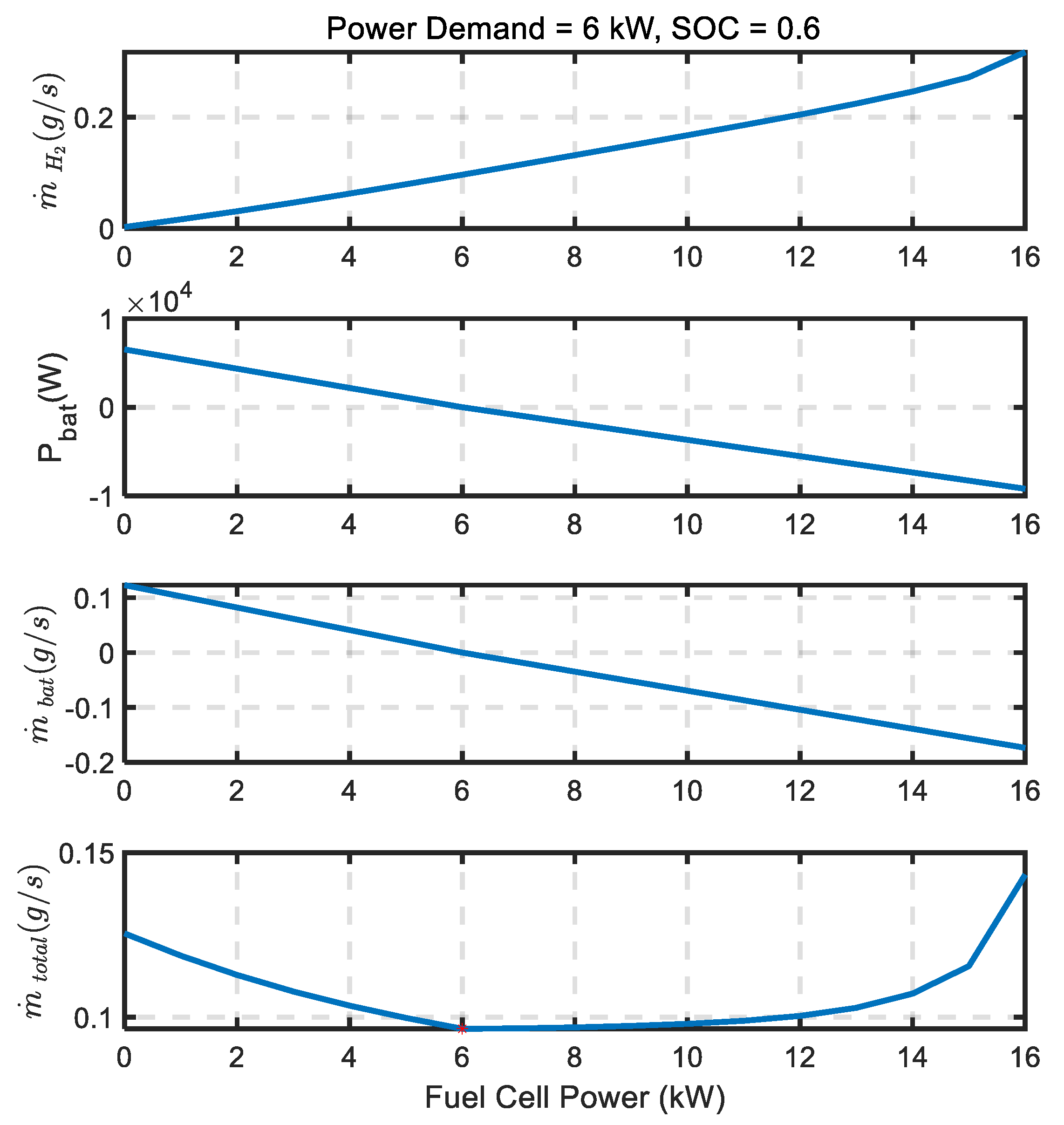
Figure 7.
Illustration of the ECMS and D-ECMS algorithm operation at power demand of 6 kW and 60% SOC.
Figure 7.
Illustration of the ECMS and D-ECMS algorithm operation at power demand of 6 kW and 60% SOC.

Figure 8.
Implemented energy management strategy model in MATLAB/Simulink.
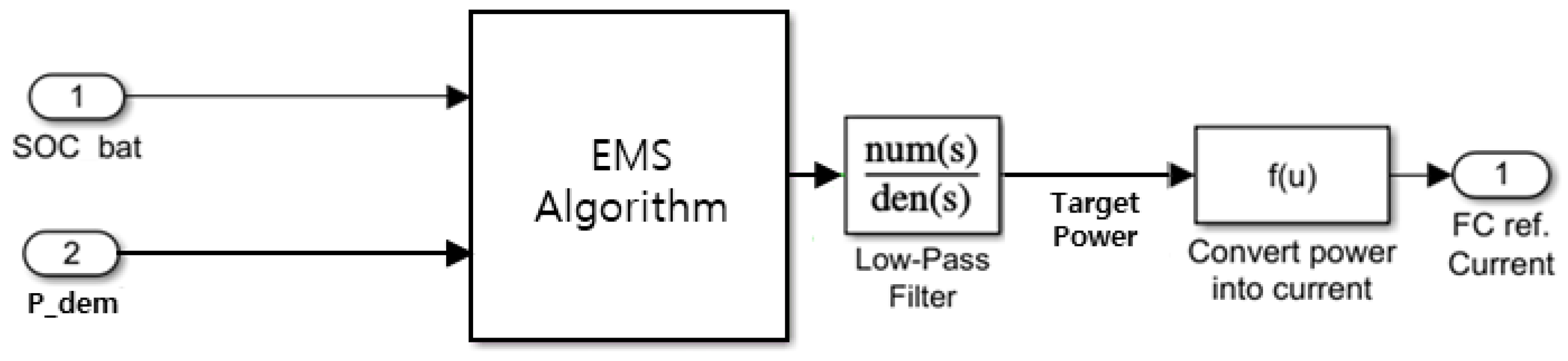
Figure 9.
Vehicle simulation results for FTP-72 cycle under rule-based control strategy: (a) Results of variation of vehicle reference and actual velocity; (b) power variation of bus, fuel cell, and battery with time; (c) voltage variation of fuel cell and battery; (d) variation in state of charge of battery and hydrogen tank.

Figure 10.
Vehicle simulation results for FTP-72 cycle under ECMS: (a) Profile on vehicle’s reference and actual velocity; (b) power variation of bus, fuel cell, and battery with time; (c) voltage variation of fuel cell and battery.
Figure 10.
Vehicle simulation results for FTP-72 cycle under ECMS: (a) Profile on vehicle’s reference and actual velocity; (b) power variation of bus, fuel cell, and battery with time; (c) voltage variation of fuel cell and battery.

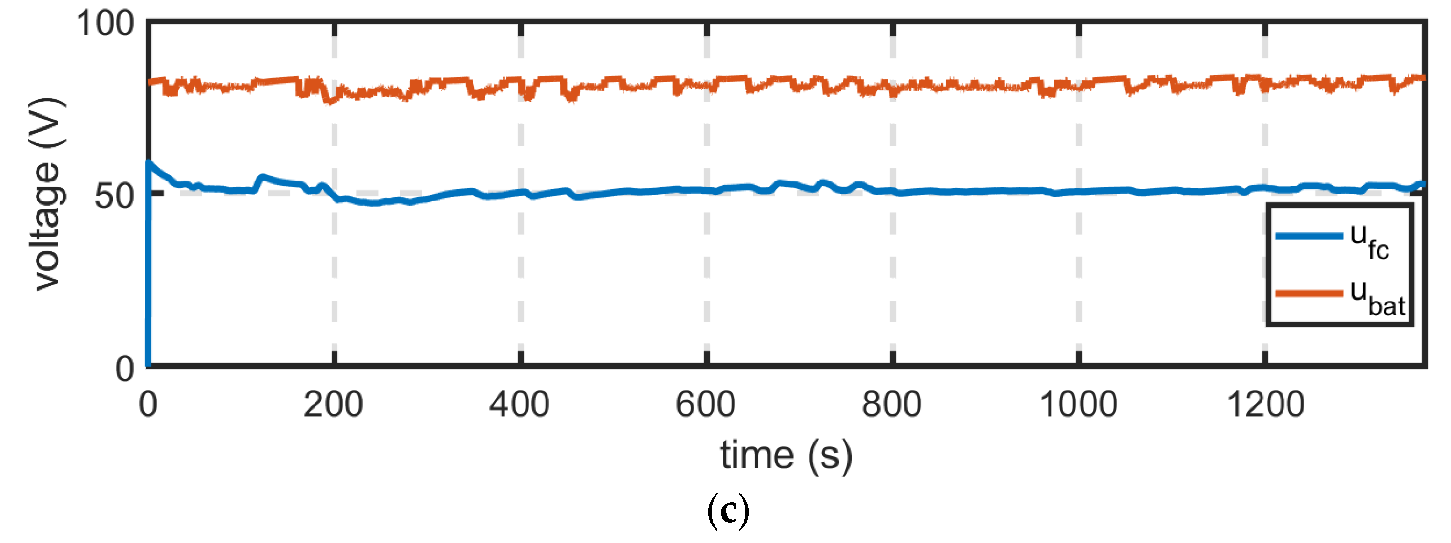
Figure 11.
Vehicle simulation results for FTP-72 cycle under D-ECMS: (a) Profile on vehicle’s reference and actual velocity; (b) power variation of bus, fuel cell, and battery with time; (c) voltage variation of fuel cell and battery.
Figure 11.
Vehicle simulation results for FTP-72 cycle under D-ECMS: (a) Profile on vehicle’s reference and actual velocity; (b) power variation of bus, fuel cell, and battery with time; (c) voltage variation of fuel cell and battery.
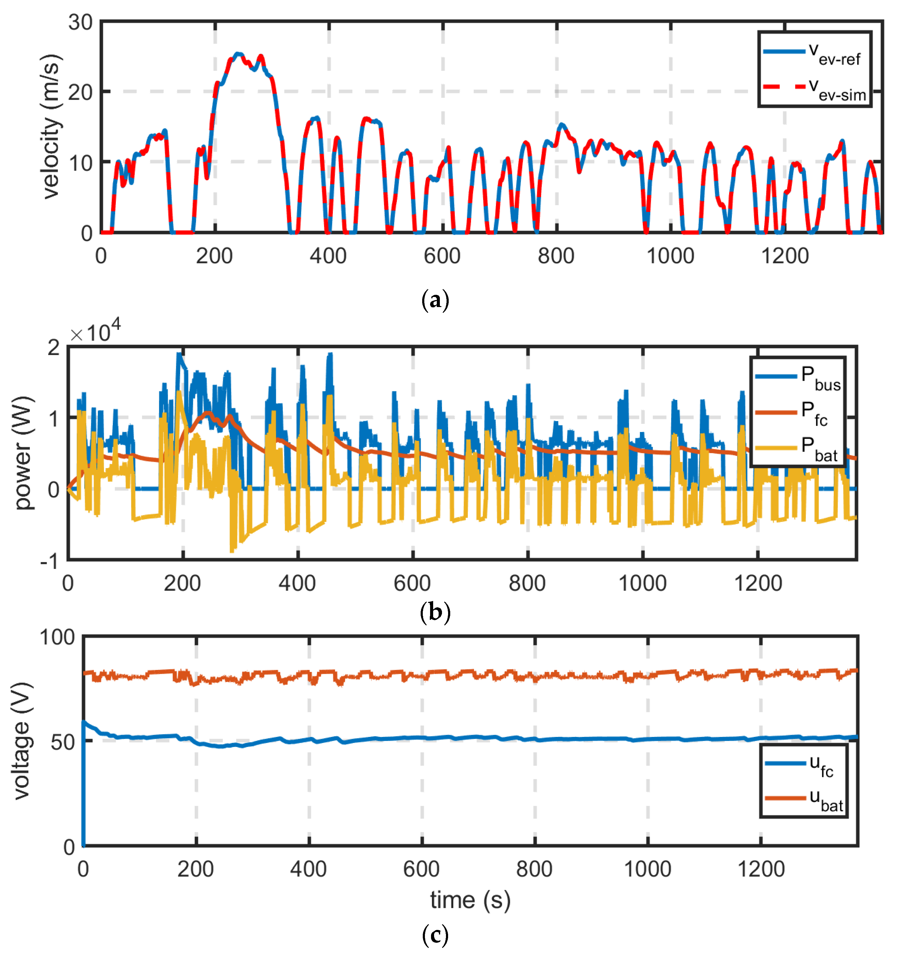
Figure 12.
Vehicle simulation results for FTP-72 cycle: (a) Variation of fuel cell power according to energy management strategy; (b) variation of battery SOC according to energy management strategy.
Figure 12.
Vehicle simulation results for FTP-72 cycle: (a) Variation of fuel cell power according to energy management strategy; (b) variation of battery SOC according to energy management strategy.

| Symbol | Description | Value |
|---|---|---|
| Inductance of smoothing inductor | 0.25 mH | |
| Resistance of smoothing inductor | 5.5 mΩ | |
| Average efficiency of chopper | 0.95 | |
| - | Power capacity of fuel cell | 16 kW |
Table 2.
Battery parameters [23].
Table 2.
Battery parameters [23].
| Symbol | Description | Value |
|---|---|---|
| Ohmic internal resistance of battery | 0.028 Ω | |
| Equivalent polarization resistance | 0.1417 Ω | |
| Equivalent polarization capacitance | 3529 F | |
| - | Capacity of battery | 40 Ah |
| Nominal voltage of battery | 80 V | |
| - | Number of cells in series for a module | 6 |
| - | Number of modules in series | 4 |
Table 3.
Vehicle parameters [23].
Table 3.
Vehicle parameters [23].
| Symbol | Description | Value |
|---|---|---|
| Vehicle mass including two passengers | 877.8 kg | |
| Equivalent mass of power train inertia | 17 kg | |
| Rolling resistance coefficient | 0.02 | |
| Gravitational acceleration | 9.81 kg m/s2 | |
| Air density | 1.223 kg/m3 | |
| Aerodynamic drag coefficient | 0.386 | |
| Vehicle frontal area | 1.813 m2 | |
| Radius of the tire | 0.2865 m |
Table 4.
Comparison of RB, ECMS, and D-ECMS on FTP-72 driving cycle.
| Item (Unit) | RB | ECMS | D-ECMS |
|---|---|---|---|
| Avg. traction power (kW) | 5.11 | 5.11 | 5.11 |
| H2 consumption (g) | 135.24 | 145.57 | 147.59 |
| Final SOC | 0.5411 | 0.6758 | 0.6851 |
| Additional H2 for recharging battery up to 100% (g) | 113.7 | 79.29 | 76.95 |
| Cost of battery recharging, , ($) | 0.3980 | 0.2775 | 0.2693 |
| Battery degradation () | 2.277 × 10⁻⁴ | 0.684 × 10⁻⁴ | 0.651 × 10⁻⁴ |
| Fuel cell degradation () | 3.217 × 10⁻⁴ | 2.749 × 10⁻⁴ | 2.744 × 10⁻⁴ |
| Driving cost, , ($) | 0.8713 | 0.7870 | 0.7859 |
| Degradation cost, , ($) | 0.3987 | 0.2087 | 0.2063 |
| Global cost, , ($) | 1.2100 | 0.9957 | 0.9922 |
Publisher’s Note: MDPI stays neutral with regard to jurisdictional claims in published maps and institutional affiliations. |
© 2021 by the authors. Licensee MDPI, Basel, Switzerland. This article is an open access article distributed under the terms and conditions of the Creative Commons Attribution (CC BY) license (https://creativecommons.org/licenses/by/4.0/).
Share and Cite
MDPI and ACS Style
Kwon, L.; Cho, D.-S.; Ahn, C. Degradation-Conscious Equivalent Consumption Minimization Strategy for a Fuel Cell Hybrid System. Energies 2021, 14, 3810. https://doi.org/10.3390/en14133810
AMA Style
Kwon L, Cho D-S, Ahn C. Degradation-Conscious Equivalent Consumption Minimization Strategy for a Fuel Cell Hybrid System. Energies. 2021; 14(13):3810. https://doi.org/10.3390/en14133810
Chicago/Turabian StyleKwon, Laeun, Dae-Seung Cho, and Changsun Ahn. 2021. "Degradation-Conscious Equivalent Consumption Minimization Strategy for a Fuel Cell Hybrid System" Energies 14, no. 13: 3810. https://doi.org/10.3390/en14133810
Note that from the first issue of 2016, this journal uses article numbers instead of page numbers. See further details here.