
Influences of Geometrical Parameters of Upstream Deflector on Performance of a H-Type Vertical Axis Marine Current Turbine

1
School of Energy and Power Engineering, University of Shanghai for Science and Technology, Shanghai 200093, China
2
Shanghai Key Laboratory of Power Energy in Multiphase Flow and Heat Transfer, University of Shanghai for Science and Technology, Shanghai 200093, China
*
Author to whom correspondence should be addressed.
Energies 2021, 14(14), 4087; https://doi.org/10.3390/en14144087
Submission received: 24 May 2021
/
Revised: 27 June 2021
/
Accepted: 30 June 2021
/
Published: 6 July 2021
(This article belongs to the Special Issue Computational Fluid Dynamics Simulations for Wind Turbines)
Abstract
:Marine current power is a kind of renewable energy that has attracted increasing attention because of its abundant reserves, high predictability, and consistency. A marine current turbine is a large rotating device that converts the kinetic energy of the marine current into mechanical energy. As a straight-bladed vertical axis marine current turbine (VAMCT) has a square or rectangular cross-section, it can thus have a larger swept area than that of horizontal axis marine current turbines (HAMCT) for a given diameter, and also have good adaptability in shallow water where the turbine size is limited by both width and depth of a channel. However, the low energy utilization efficiency of the VAMCT is the main bottleneck that restricts its application. In this paper, two-dimensional numerical simulations were performed to investigate the effectiveness of an upstream deflector on improving performance of the straight-bladed (H-type) marine current turbine. The effects of various key geometrical parameters of the deflector including position, length, and installation angle on the hydrodynamic characteristics of the VAMCT were then systematically analyzed in order to explore the mechanism underlying the interaction between the deflector and rotor of a VAMCT. As a result, the optimal combination of geometrical parameters of the deflector by which the maximum energy utilization efficiency was achieved was a 13.37% increment compared to that of the original VAMCT. The results of this work show the feasibility of the deflector as a potential choice for improving the energy harvesting performance of a VAMCT with simple structure and easy implementation.
1. Introduction
As a kind of abundant, clean, and renewable energy source, marine current power generation is becoming more and more attractive in the face of climate change impacts [1]. Much like a wind turbine, a marine current turbine is a device that captures the kinetic energy from tidal-driven marine currents and converts it into electricity, and can also be classified as either a horizontal axis marine current turbine (HAMCT) or vertical axis marine current turbine (VAMCT) [2]. Compared with HAMCTs, VAMCTs can operate with the incoming flow from any direction and most of its machine components can be installed above the water surface, allowing ease of access for maintenance, repairs, and upgrades [3]. Due to its advantages of simple structure, convenient installation, and strong adaptability to water depth, the application of the VAMCT has stimulated the extensive interests of researchers in recent years. As a result, rapid progress has been made in the technical development of the VAMCT, and a number of marine current prototypes are being developed and tested in real coastal sites [4]. Compared to their horizontal axis counterparts, VAMCTs are of relatively low energy utilization efficiency and thus they are not yet in widespread use. Therefore, increasing the hydrodynamic performance of a VAMCT at different tip speed ratios is vitally important in order to promote the large-scale and industrialized exploitation of marine current energy, which is distributed in different regions. Nowadays, many researchers are committed to exploring different methods to improve the performance of VAMCTs for hydrokinetic energy harvesting.
Ji et al. [5] analyzed the effects of spoke and clamp, incoming flow velocity, and blade chord length on the hydrodynamic characteristics and load characteristics of the tidal current turbine through experiments, and found that the energy conversion rate of a vertical axis tidal turbine could be effectively improved by increasing velocity and changing the blade chord length. Xiao et al. [6] applied the flaps to the VAMCT, and compared to the original turbine, the averaged power coefficient reached 28% enhancement. Priegue et al. [7] explored the effect of blade roughness on the performance of a VAMCT and discovered that the rougher the blade surface was, the worse the performance of the turbine became. Chen et al. [8] studied the influence of an active variable-pitch control strategy on the dynamic performance of a VAMCT using numerical simulation. Their results showed that the active variable-pitch control could significantly improve the dynamic performance of the VAMCT and the optimal power coefficient of the turbine was increased. Although a substantial improvement in energy efficiency of the VAMCT was achieved, this type of active flow control method requires external energy input and a complicated structure and control system, which make it difficult to be implemented in practice.
Previous studies [9,10,11] indicated that when a flat plate deflector was placed upstream of a vertical axis wind turbine, it was beneficial to the wind speed accelerating and, as a result, effectively improved the overall performance of the wind turbine. So far, research on vertical axis wind turbines with an upstream deflector has mainly focused on improving the aerodynamic performance of co- and counter-rotating twin vertical axis wind turbines [12,13,14,15,16]. In these studies, the wind direction was fixed and the deflector was normally mounted right in front of the wind turbine. In practice, however, wind can change direction throughout the day. Under such circumstances, the deflector may even adversely affect the power output of the vertical axis wind turbine once the wind switches direction. Therefore, the use of an upstream deflector as a passive measure to increase the efficiency of VAMCTs has a fairly limited scope of application. Unlike wind, marine currents are predictable, day to day, and all year round. Thereby, the fixed deflector is more suitable for performance enhancement of a VAMCT as it is simple and easily implementable. In this paper, the effectiveness of using an upstream flat plate to maximize the energy-harvesting capability of a straight-bladed Darrieus vertical axis marine current turbine (H-type VAMCT) was numerically investigated, and influences of geometrical parameters of the deflector including the position (distance) from the turbine rotor, length, and installation angle relative to the incoming flow were systematically analyzed. The analysis was focused on the interaction between the deflector plate and flow field around the turbine, with the aim to gain a better understanding of the underlying mechanism involved by which the effectiveness of the deflector can be achieved to the largest possible extent. This work examined the feasibility of using an upstream obstacle such as an elongated naturally occurring ridge or artificially constructed wall to promote the hydrodynamic performance of a VAMCT, and thus the findings could be of practical value for harnessing the hydrokinetic energy from flowing streams.
2. Numerical Methodology
2.1. Hydrodynamic Parameters of VAMCT
The main parameters of the VAMCT include tip speed ratio, moment coefficient, and power coefficient. Tip speed ratio is defined as the ratio of the blade tangential speed to the freestream velocity, which reflects the working conditions of the VAMCT:
where ω is the angular velocity of the rotating blades, U∞ is the freestream velocity, and R is the rotating radius of the turbine. When the free stream velocity and rotating radius are determined, different angular velocity can be obtained by changing the tip speed ratio. To evaluate the dynamic performance of VAMCT, there are two significant parameters: the power coefficient Cp and the moment coefficient Cm, which can be expressed as:
where P is the power of the turbine, M is the moment of the turbine, ρ is the fluid density, A is the turbine swept area, and R is the radius of the rotor.
The averaged power coefficient Cp in one rotation cycle can be expressed as:
where T is the rotating period.
2.2. Geometrical Parameters of the Turbine and CFD Simulation Strategy
Two-dimensional numerical simulations are conducted on the VAMCT using the computational fluid (CFD) method based on ANSYS workbench, and the geometrical parameters of the turbine are presented in Table 1. Re = 300,000 is close to laminar flow over most of the blade. The sliding mesh strategy is applied to realize the rotating motion of the turbine. As shown in Figure 1, the computational domain consists of two parts: the ring-shaped rotation domain and the stator domain. The outside region is a large rectangle area, and the velocity inlet is 38 m (38D) away from the rotor. To ensure the accuracy of near-wall simulation of the blade, a structured mesh is set on the blade surface, and the normal distance to the nearest wall is set as 1.24 × 10⁻⁵ mm. The mesh is refined at the leading and trailing edge of the blade, as illustrated in Figure 1b. Abdolrahim, Francesco, and Daroczy [17,18,19] found that Transition Shear-Stress Transport (TSST) model and Shear-Stress Transport (SST) k-ω turbulence model could accurately simulate the flow field characteristics around the VAMCT, so the SST k-ω turbulence model is selected.
The SST k-ω turbulence model is a two-equation eddy viscosity turbulence model, which is based on the baseline k-ω mode and considers the transport of the turbulence shear stress in the definition of the turbulent viscosity [20]. The Wilcox k-ω turbulence model is utilized in the inner region of the boundary layer and the standard k-ε model is utilized in free shear flows and the outer area [21]. The transport equation for the turbulent kinetic energy k is:
The transport equation for the specific consumption rate ω is:
where u is the fluid velocity; k and μ are the turbulent kinetic energy and the turbulent scale parameter; F1 and F2 are mixing functions; and γ σk, σw, and σw2 are the empirical coefficients. The Reynolds stress τij can be expressed by:
where Sij represents the mean rate of deformation, and δij means the Kronecker delta function. The transport behavior can be obtained by a formula that limits the eddy viscosity μt:
In this paper, an azimuthal increment of 0.5° is adopted and the SIMPLE segregated algorithm is chosen. All spatial and time terms are discretized using second order implicit transient schemes. The Reynolds unsteady incompressible Naiver-Stokes equations are solved and the averaged power coefficients of the turbine at different tip speed ratios are obtained.
2.3. Mesh Independency Study
To achieve the mesh-independent solution, three cases with 164,000, 315,000, and 582,000 cells are discussed. The results listed in Table 2 show the comparison of averaged power coefficients at λ = 2.6 and 3.2. It could be seen that at λ = 2.6, the case with 164,000 cells underestimates the averaged power coefficient. When the cell is refined, the difference between the averaged power coefficient is less than 2%, and the numerical results can be considered to be independent of mesh. The total mesh number of 315,000 is employed in the following numerical simulations in this paper.
2.4. Model Validation
Referring to the method adopted by researchers Ye, Wang, and Sun [22,23,24], the two-dimensional numerical simulation results are compared with the experimental data [25] and the numerical results [26] under the same conditions to verify the reliability and accuracy of the proposed model, as shown in Figure 2. It can be seen that the trend of curve obtained by the simulation in this paper is roughly consistent with the experimental value, and it is relatively close to the simulation results, which verifies that the numerical analysis method in this paper can accurately predict the dynamic characteristics of the turbine.
3. Results and Discussions
3.1. Spatial Arrangement of Upstream Deflector Relative to the Turbine Rotor
In the following section, two-dimensional simulations are conducted, and influences of geometrical parameters of the upstream flat plate on the hydrodynamic performance of the VAMCT are analyzed. As shown in Table 3, these parameters are the distance between the deflector and turbine rotor l, the deflector length w, and the deflector installation angle β (the angle between the deflector and the free stream). The spatial arrangement of an upstream flat plate deflector relative to the turbine rotor is sketched in Figure 3. The numerical simulations are based on the NACA0021 blade with a constant upstream velocity U∞ = 2 m/s.
3.2. Effect of the Distance between Deflector and Turbine Rotor
Figure 4 shows the influence of the deflector position on the averaged power coefficient. The corresponding parameters are w/d = 0.56, β = 45.0°, and the λ varies from 2.0 to 3.2. For the turbine without a deflector, the maximum power coefficient is 43.3% at the optimal tip speed ratio λ = 2.4. For l/d = 0.69, 1.00, and 1.29, the maximum power coefficient of the VAMCT is 40.3%, 49.1%, and 47.3%, respectively. The results show that the deflector with l/d = 1.00 could effectively improve the hydrodynamic performance of VAMCT.
Figure 5 shows the variation of the instantaneous moment coefficient Cm of one hydrofoil in a rotation cycle at λ = 2.4. It can be seen that the increment in the moment coefficient caused by the deflector is mainly concentrated in the upstream area (θ = 0–180°), while less improvement is achieved in the downstream (θ = 181–360°). Figure 6 presents the velocity contour for VAMCT with a deflector of different l/d. When the fluid passes through the deflector, it can be observed that the fluid at the upper and lower ends of the plate is accelerated. When the deflector is close to the turbine (l/d = 0.69), the accelerating fluid has a significant effect on the blade, and the peak value of the moment coefficient curve is greatly increased. However, the low-speed fluid behind the deflector also affects the hydrodynamic performance of the hydrofoil. It causes the Cm to drop sharply in the range of θ = 105–150°, and as a result, there exists a negative effect on the averaged power coefficient of the VAMCT. For l/d = 1.00, it could be found that the accelerating fluid at the upper side of the deflector deflects toward the lower side, which weakens the influence of low-speed fluid on the performance of the turbine. Therefore, without the interference of the near-wake region, the averaged power coefficient of the turbine is improved. As the distance further increases to l/d = 1.29, the fluid velocity encountered by the VAMCT is decreased. Although the averaged power coefficient of the turbine blade still improves, it is lower than that of the VAMCT with the deflector of l/d = 1.00.
3.3. Effect of the Deflector Length
Keeping l/d = 1.00 and β = 45.0°, the effect of deflector length on hydrodynamic performance of the VAMCT is analyzed by varying w/d from 0.29 to 0.85, as shown in Figure 7. For w/d = 0.29, 0.56, and 0.85, the maximum power coefficient of the turbine is 45.1%, 49.1%, and 46.8%. Compared with the turbine without a deflector, the maximum power coefficient is increased by 3.97%, 13.37%, and 7.99%, respectively.
Figure 8 shows the instantaneous moment coefficient of one blade of the VAMCT with a deflector of different length during one rotation cycle at λ = 2.4 and λ = 3.2. It could be found that as the length of the deflector increases, the peak value of the moment coefficient Cm is improved, due to the fact that more accelerating fluid is directed to the turbine. Figure 9 shows the velocity contour for the flow field near the VAMCT. When λ = 2.4, in the range of θ = 0–120°, the improvement in fluid velocity causes an increase in the instantaneous moment coefficient. The accelerating fluid on the upper side of the short deflector (w/d = 0.29) has a weak effect on the hydrofoil, and there is a slight increment in the averaged power coefficient. For w/d = 0.85, the instantaneous moment coefficient has the largest increment in the range of θ = 0–120°. However, as shown in Figure 9and Figure 10, both the free shedding vortex formed at the upper side of the deflector and the near-wake region reduce the flow velocity near the hydrofoil in the range of θ = 120–210°, resulting in a sharp decrease in the instantaneous moment coefficient. The performance improvement of a VAMCT depends on the sum of the moment increment and moment decrease in one period, so the averaged power coefficient of the deflector with w/d = 0.85 is inferior to that of the deflector with w/d = 056 at λ = 2.4. When the turbine operates at a high tip speed ratio, the blockage effect is strengthened and the accelerated flow tends to go around the turbine. Therefore, when w/d = 0.29 and 0.56, the effects of the accelerating fluid on the upper side of the deflector are weakened, resulting in a decrease in the instantaneous moment coefficient of the turbine blade in the range of θ = 0–120°. However, the flow direction of the accelerating fluid from the deflector with w/d = 0.85 is basically consistent with the mainstream direction, and compared to λ = 2.4, the velocity of the fluid around the blade does not change remarkably. Hence, at a high tip speed ratio, the increase in the moment coefficient of the VAMCT of the deflector with w/d = 0.85 is significantly higher than that of the deflector with other lengths, as shown in Figure 7.
3.4. Effect of Installation Angle of the Deflector
In this section, the influence of deflector installation angle β (the angle between the deflector and the freestream) on the hydrodynamic performance of VAMCTs is explored. The corresponding parameters are l/d = 1.00 and w/d = 0.56. The selected installation angles of the deflector are 45.0°, 67.5°, 112.5°, and 135.0°, respectively. Figure 11 shows the effect of the installation angle of the deflector on the averaged power coefficient of the VAMCT at different λ. Compared with the turbine without a deflector, the averaged power coefficient of the VAMCT is significantly increased when β is 45.0°, 67.5°, and 112.5°. When β = 67.5°, the averaged power coefficient is greatly improved at different λ, and a maximum increment of about 14.5% is achieved when λ = 2.4. When β = 135.0°, the deflector has a negative effect on the hydrodynamic performance of the turbine, and its averaged power coefficient is greatly reduced.
Figure 12 shows the variation in instantaneous moment coefficient for the deflector with a different installation angle. At λ = 2.4, when θ = 25–90°, the averaged power coefficient of the VAMCT gradually decreases with the increase in β. For β = 45°, from the velocity contour of the flow field around the turbine, as shown in Figure 13a, the accelerating fluid on the upper side of the deflector deflects to the lower side. The change in the velocity and direction of the fluid near the blade induces a large angle of attack, which is conducive to the generation of the positive torque of the turbine. When θ = 90–115°, an accelerating flow channel is formed between the blade and the deflector [12]. In the case of β = 67.5° and 112.5°, the accelerating fluid is nearly consistent with the main flow direction and the area of the flow channel is the smallest, so there exists a significant improvement in the peak value of the instantaneous moment coefficient curve. However, in the range of θ = 120–150°, the near-wake region behind the deflector is extended and has negative effects on the turbine performance. Additionally, the shedding vortex from the deflector of β = 67.5° and 112.5° collides with the blade, which also greatly obstructs the energy obtained by the blade from the fluid, as shown in Figure 14. As β further increases to 135°, no obvious accelerating fluid on the upper side of the deflector can be observed, and the deflector prevents part of the fluid from going through the turbine, leading to a significant decrease in the hydrodynamic performance of the VAMCT.
When λ = 3.2, the instantaneous moment coefficient of the VAMCT decreases due to the blockage effect. As can be seen from Figure 13b, compared with the deflector of β = 67.5° and 112.5°, the region and the speed of the accelerating fluid on the upper side of the deflector of β = 45° are reduced, leading to a significant drop in the averaged power coefficient. Although the deflector of β = 67.5° and β = 112.5° can improve the averaged power coefficient of the VAMCT at different λ, the effect of the low-speed region behind the deflector causes the fluctuation amplitude of the moment coefficient to increase in the range of θ = 0–180°, which is not conducive to the safe and stable operation of the turbine.
4. Conclusions
In this paper, the influence of the position, length, and installation angle of a single flat plate deflector on the hydrodynamic performance of a vertical axis marine current turbine were studied by numerical simulation. The main conclusions are as follows:
- When the deflector is too close to the rotor, the low-speed flow behind the deflector has a negative effect on the hydrodynamic performance of the turbine and the averaged power coefficient obviously decreases. When the deflector is away from the turbine, the influence of the accelerating fluid on the blade is weakened, so there exists a proper distance between the deflector and the rotor, which greatly improves the averaged power coefficient of the VAMCT.
- With the increase in the deflector length, more accelerated fluid is guided to the turbine. At the same time, the low-speed fluid region behind the deflector is also extended, and it would deteriorate the energy extraction efficiency of the turbine. Therefore, it is crucial to choose a deflector with an appropriate length to improve the averaged power coefficient of the VAMCT.
- The installation angle of the deflector has a significant impact on the hydrodynamic performance of the turbine. Although the deflector with β = 67.5° and 112.5° can improve the performance of the vertical axis marine current turbine, the effect of the low-speed region behind the deflector causes the fluctuation amplitude of the moment coefficient to increase, which is not conducive to the safe and stable operation of the turbine.
- In this paper, a proper combination of deflector parameters, namely, l/d = 1.00, w/d = 0.56, and β = 45°, was identified. Compared with the turbine without a deflector, a maximum increase of 13.37% is achieved at the optimal tip speed ratio λ = 2.4. In future works, further optimization of the geometry parameters of the deflector would be performed by using orthogonal array design, and the shape of the deflector will also be considered.
Author Contributions
Conceptualization, X.S.; methodology, D.Z.; validation, D.Z.; formal analysis, D.Z.; investigation, D.Z.; writing—original draft preparation, D.Z.; writing—review and editing, X.S. All authors have read and agreed to the published version of the manuscript.
Funding
This work was supported by the National Natural Science Foundation of China under Grant No. 11202123.
Conflicts of Interest
The authors declare no conflict of interest.
Nomenclature
| θ | Azimuth angle |
| c | Hydrofoil chord length |
| Cp | Averaged power coefficient |
| λ | Tip speed ratio |
| l | Distance between deflector and rotor |
| β | Deflector installation angle |
| w | Length of the deflector |
| U∞ | Freestream velocity far upstream |
| D | Diameter of the turbine |
| Cm | Moment coefficient |
| Cp | Power coefficient |
| Re | Reynolds number |
| M | Moment of the turbine |
| P | Power of the turbine |
| T | Rotating period |
| ρ | Density of the fluid |
| ω | Angular velocity |
| A | Turbine swept area |
References
- Rourke, F.O.; Boyle, F.; Reynolds, A. Tidal energy update 2009. Appl. Energy 2010, 87, 398–409. [Google Scholar] [CrossRef]
- The, J.; Yu, H.S. A critical review on the simulations of wind turbine aerodynamics focusing on hybrid RANS-LES methods. Energy 2017, 138, 257–289. [Google Scholar] [CrossRef]
- Bhutta, M.M.A.; Hayat, N.; Farooq, A.U.; Ali, Z.; Jamil, S.R.; Hussain, Z. Vertical axis wind turbine—A review of various configurations and design techniques. Renew. Sustain. Energy Rev. 2012, 16, 1926–1939. [Google Scholar] [CrossRef]
- Ma, Y.; Hu, C.; Li, Y.L.; Deng, R. Research on the Hydrodynamic Performance of a Vertical Axis Current Turbine with Forced Oscillation. Energies 2018, 11, 20. [Google Scholar] [CrossRef] [Green Version]
- Ji, R.; Sheng, Q.; Zhang, L.; Dong, Y.; Zhang, X. Experimental study on hydrodynamic model of vertical-axis tidal current turbine with fixed-blade propeller. J. Ocean. Technol. 2018, 37, 72–82. [Google Scholar]
- Xiao, Q.; Liu, W.; Incecik, A. Flow control for VATT by fixed and oscillating flap. Renew. Energy 2013, 51, 141–152. [Google Scholar] [CrossRef]
- Priegue, L.; Stoesser, T. The influence of blade roughness on the performance of a vertical axis tidal turbine. Int. J. Mar. Energy 2017, 17, 136–146. [Google Scholar] [CrossRef]
- Chen, B.; Su, S.; Viola, I.M.; Greated, C.A. Numerical investigation of vertical-axis tidal turbines with sinusoidal pitching blades. Ocean. Eng. 2018, 155, 75–87. [Google Scholar] [CrossRef] [Green Version]
- Wong, K.H.; Chong, W.T.; Sukiman, N.L.; Poh, S.C.; Shiah, Y.-C.; Wang, C.-T. Performance enhancements on vertical axis wind turbines using flow augmentation systems: A review. Renew. Sustain. Energy Rev. 2017, 73, 904–921. [Google Scholar] [CrossRef]
- Naseem, A.; Uddin, E.; Ali, Z.; Aslam, J.; Shah, S.R.; Sajid, M.; Zaidi, A.A.; Javed, A.; Younis, M.Y. Effect of vortices on power output of vertical axis wind turbine (VAWT). Sustain. Energy Technol. Assess. 2020, 37, 11. [Google Scholar] [CrossRef]
- Wong, K.H.; Chong, W.T.; Sukiman, N.L.; Shiah, Y.-C.; Poh, S.C.; Sopian, K.; Wang, W.-C. Experimental and simulation investigation into the effects of a flat plate deflector on vertical axis wind turbine. Energy Convers. Manag. 2018, 160, 109–125. [Google Scholar] [CrossRef]
- Jiang, Y.C.; Zhao, P.D.; Stoesser, T.; Wang, K.; Zou, L. Experimental and numerical investigation of twin vertical axis wind turbines with a deflector. Energy Convers. Manag. 2020, 209, 112588. [Google Scholar] [CrossRef]
- Qasemi, K.; Azadani, L.N. Optimization of the power output of a vertical axis wind turbine augmented with a flat plate deflector. Energy 2020, 202, 10. [Google Scholar] [CrossRef]
- Kim, D.; Gharib, M. Efficiency improvement of straight-bladed vertical-axis wind turbines with an upstream deflector. J. Wind Eng. Ind. Aerodyn. 2013, 115, 48–52. [Google Scholar] [CrossRef]
- Jin, X.; Wang, Y.M.; Ju, W.B.; He, J.; Xie, S.Y. Investigation into parameter influence of upstream deflector on vertical axis wind turbines output power via three-dimensional CFD simulation. Renew. Energy 2018, 115, 41–53. [Google Scholar] [CrossRef]
- Kim, D.; Gharib, M. Unsteady loading of a vertical-axis turbine in the interaction with an upstream deflector. Exp. Fluids 2014, 55, 1658. [Google Scholar] [CrossRef]
- Rezaeiha, A.; Montazeri, H.; Blocken, B. On the accuracy of turbulence models for CFD simulations of vertical axis wind turbines. Energy 2019, 180, 838–857. [Google Scholar] [CrossRef]
- Daroczy, L.; Janiga, G.; Petrasch, K.; Webner, M.; Thevenin, D. Comparative analysis of turbulence models for the aerodynamic simulation of H-Darrieus rotors. Energy 2015, 90, 680–690. [Google Scholar] [CrossRef]
- Balduzzi, F.; Bianchini, A.; Maleci, R.; Ferrara, G.; Ferrari, L. Critical issues in the CFD simulation of Darrieus wind turbines. Renew. Energy 2016, 85, 419–435. [Google Scholar] [CrossRef]
- Menter, F.R. Two-equation eddy-viscosity turbulence models for engineering applications. AIAA J. 1994, 32, 1598–1605. [Google Scholar] [CrossRef] [Green Version]
- Tong, H.; Fang, J.; Guo, J.; Lin, K.; Wang, Y. Numerical Simulation of Unsteady Aerodynamic Performance of Novel Adaptive Airfoil for Vertical Axis Wind Turbine. Energies 2019, 12, 4106. [Google Scholar] [CrossRef] [Green Version]
- Ye, L.; Sander, M. Calisal. Three-dimensional effects and arm effects on modeling a vertical axis tidal current turbine. Renew. Energy 2010, 35, 2325–2334. [Google Scholar]
- Wang, Y.; Sun, X.J.; Zhu, B.; Zhang, H.J.; Huang, D.G. Effect of blade vortex interaction on performance of Darrieus-type cross flow marine current turbine. Renew. Energy 2016, 86, 316–323. [Google Scholar] [CrossRef]
- Sun, J.; Huang, D. Numerical investigation on aerodynamic performance improvement of vertical-axis tidal turbine with super-hydrophobic surface. Ocean. Eng. 2020, 217, 107995. [Google Scholar] [CrossRef]
- Raciti Castelli, M.; Englaro, A.; Benini, E. The Darrieus wind turbine: Proposal for a new performance prediction model based on CFD. Energy 2011, 36, 4919–4934. [Google Scholar] [CrossRef]
- Hashem, I.; Mohamed, M.H. Aerodynamic performance enhancements of H-rotor Darrieus wind turbine. Energy 2018, 142, 531–545. [Google Scholar] [CrossRef]
Figure 1.
(a) General view of the computational domain and mesh used for the present calculations and (b) enlarged view of grid around NACA0021 hydrofoil.
Figure 1.
(a) General view of the computational domain and mesh used for the present calculations and (b) enlarged view of grid around NACA0021 hydrofoil.


Figure 2.
Comparison between present numerical results and previously published studies. Developed from [25,26].

Figure 3.
Spatial arrangement of upstream deflector relative to the turbine rotor.

Figure 4.
Averaged power coefficient Cp vs. λ for varying the distance (l/d) between deflector and turbine rotor.
Figure 4.
Averaged power coefficient Cp vs. λ for varying the distance (l/d) between deflector and turbine rotor.

Figure 5.
Instantaneous moment coefficient Cm of one hydrofoil of VAMCT with the deflector of different position.
Figure 5.
Instantaneous moment coefficient Cm of one hydrofoil of VAMCT with the deflector of different position.
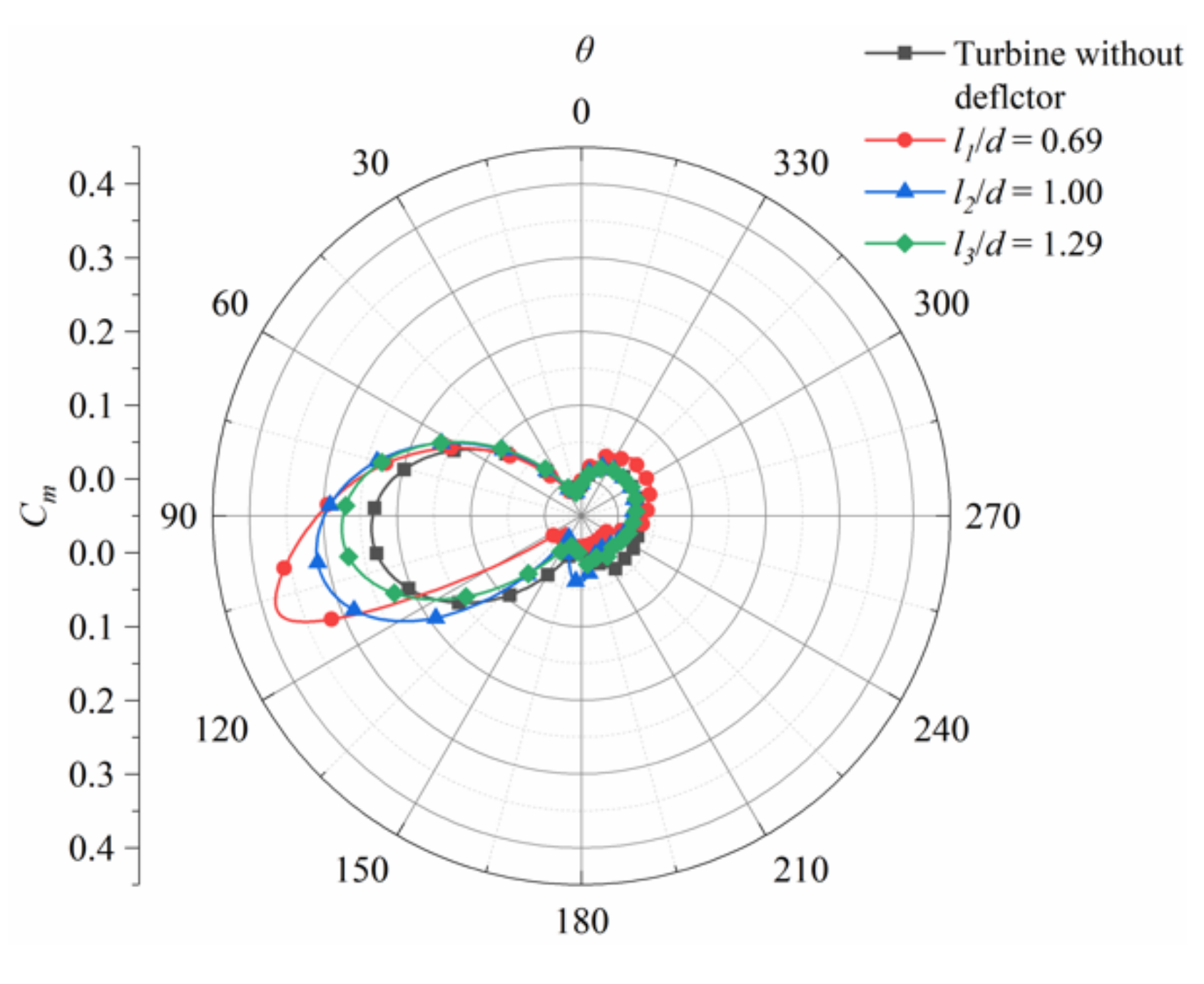
Figure 6.
Velocity contour for the VAMCT with the deflector of different position when λ = 2.4.

Figure 7.
Averaged power coefficient Cp vs. λ for varying the deflector length (w/d).

Figure 8.
Instantaneous moment coefficient Cm as a function of blade azimuthal position for a complete revolution with the deflector of different length when (a) λ = 2.4 and (b) λ = 3.2.
Figure 8.
Instantaneous moment coefficient Cm as a function of blade azimuthal position for a complete revolution with the deflector of different length when (a) λ = 2.4 and (b) λ = 3.2.

Figure 9.
Velocity contour for the VAMCT with the deflector of different length when (a) λ = 2.4 and (b) λ = 3.2.
Figure 9.
Velocity contour for the VAMCT with the deflector of different length when (a) λ = 2.4 and (b) λ = 3.2.
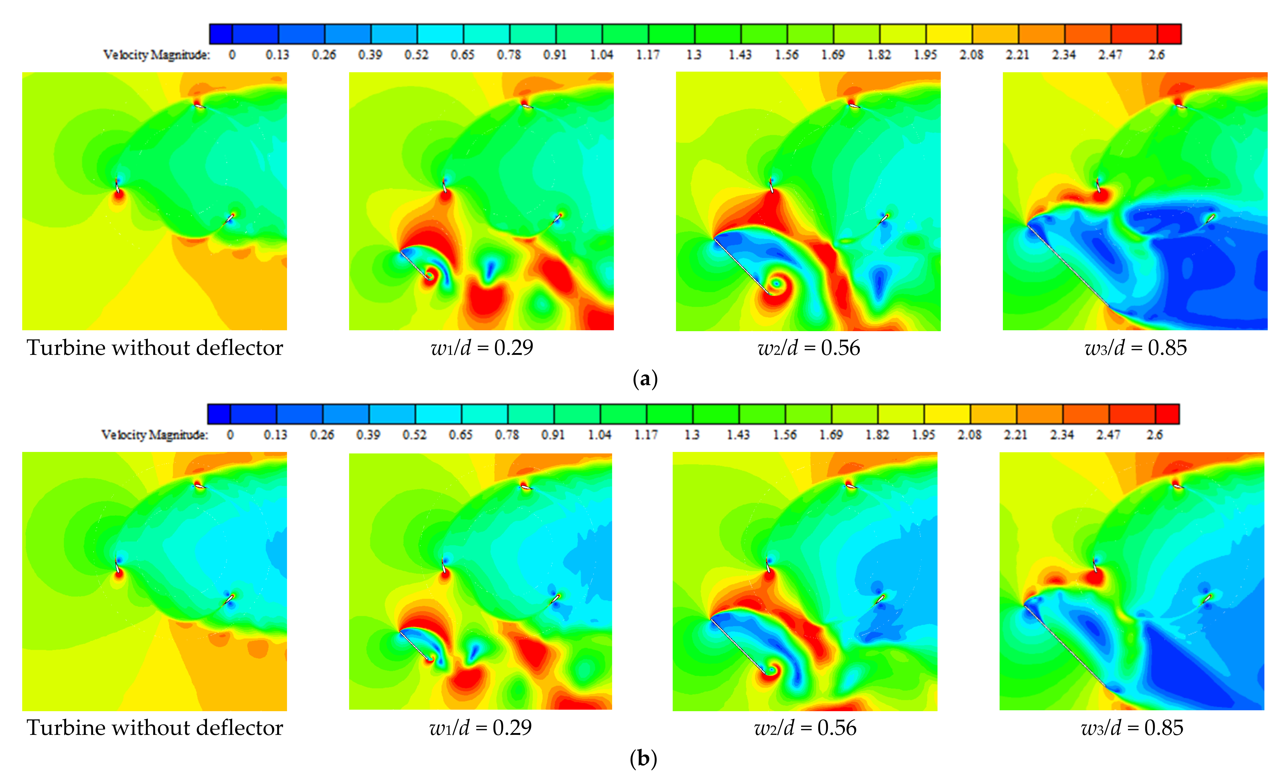
Figure 10.
Vorticity contours around a single blade and deflector with different lengths at λ = 2.4 (θ = 135°).
Figure 10.
Vorticity contours around a single blade and deflector with different lengths at λ = 2.4 (θ = 135°).

Figure 11.
Averaged power coefficient Cp vs. λ for varying the installation angle of deflector (β).

Figure 12.
Instantaneous moment coefficient Cm as a function of azimuthal position with the deflector of different angle at (a) λ = 2.4 and (b) λ = 3.2.
Figure 12.
Instantaneous moment coefficient Cm as a function of azimuthal position with the deflector of different angle at (a) λ = 2.4 and (b) λ = 3.2.

Figure 13.
Close-up view of velocity contours around a rotor blade with upstream deflector with different lengths at (a) λ = 2.4 and (b) λ = 3.2.
Figure 13.
Close-up view of velocity contours around a rotor blade with upstream deflector with different lengths at (a) λ = 2.4 and (b) λ = 3.2.


Figure 14.
Vorticity contours around a single blade and deflector with different installation angles at λ = 2.4 (θ = 125°).
Figure 14.
Vorticity contours around a single blade and deflector with different installation angles at λ = 2.4 (θ = 125°).


Table 1.
Geometrical parameters of Darrieus turbine rotor used for validation.
| Parameter | Value |
|---|---|
| Rotor diameter | 1030 mm |
| Number of blades | 3 |
| Blade profile | NAC0021 |
| chord | 85.8 mm |
| Re | 300,000 |
Table 2.
Averaged power coefficients computed with various numbers of cells.
| Tip Speed Ratio λ | Total Cell Number | Averaged Power Coefficient Cp | Difference (%) |
|---|---|---|---|
| 2.6 | 164,000 | 0.41808 | - |
| 315,000 | 0.43186 | 3.30 | |
| 582,000 | 0.4368 | 1.14 | |
| 3.2 | 164,000 | 0.34112 | - |
| 315,000 | 0.34208 | 0.28 | |
| 582,000 | 0.34336 | 0.66 |
Table 3.
Geometrical parameters of the deflector.
| Parameter | Value |
|---|---|
| Deflector thickness t (mm) | 10 |
| Ratio of distance between deflector and turbine rotor to turbine diameter l/d | 0.69, 1.00, 1.29 |
| Ratio of deflector length to turbine diameter w/d | 0.29, 0.56, 0.85 |
| Deflector installation angle β (°) | 45.0°, 67.5°, 112.5°, 135.0° |
Publisher’s Note: MDPI stays neutral with regard to jurisdictional claims in published maps and institutional affiliations. |
© 2021 by the authors. Licensee MDPI, Basel, Switzerland. This article is an open access article distributed under the terms and conditions of the Creative Commons Attribution (CC BY) license (https://creativecommons.org/licenses/by/4.0/).
Share and Cite
MDPI and ACS Style
Zhou, D.; Sun, X. Influences of Geometrical Parameters of Upstream Deflector on Performance of a H-Type Vertical Axis Marine Current Turbine. Energies 2021, 14, 4087. https://doi.org/10.3390/en14144087
AMA Style
Zhou D, Sun X. Influences of Geometrical Parameters of Upstream Deflector on Performance of a H-Type Vertical Axis Marine Current Turbine. Energies. 2021; 14(14):4087. https://doi.org/10.3390/en14144087
Chicago/Turabian StyleZhou, Donghai, and Xiaojing Sun. 2021. "Influences of Geometrical Parameters of Upstream Deflector on Performance of a H-Type Vertical Axis Marine Current Turbine" Energies 14, no. 14: 4087. https://doi.org/10.3390/en14144087
Note that from the first issue of 2016, this journal uses article numbers instead of page numbers. See further details here.