
Issues and Challenges for HVDC Extruded Cable Systems


Department of Electrical Energy Engineering and Information “Guglielmo Marconi”, University of Bologna, Viale Risorgimento 2, 40136 Bologna, Italy
Energies 2021, 14(15), 4504; https://doi.org/10.3390/en14154504
Submission received: 14 June 2021
/
Revised: 6 July 2021
/
Accepted: 9 July 2021
/
Published: 26 July 2021
(This article belongs to the Topic Innovative Techniques for Smart Grids)
Abstract
:The improved features of AC/DC converters, the need to enhance cross-country interconnections, the will to make massive remote renewable energy sources available, and the fear of populations about overhead lines have fostered HVDC cable transmission all over the world, leading in the last two decades to an exponential increase of commissioned HVDC cable projects, particularly of the extruded insulation type. Comprehensive surveys of the issues to be faced by HVDC extruded cable systems appeared in the literature some years ago, but they are not so up-to-date, as HVDC extruded cable technology is developing fast. Therefore, the contribution this paper aims at giving is a systematic, comprehensive and updated summary of the main present and future issues and challenges that HVDC cable systems have to face to further improve their performance and competitiveness, so as to meet the growing quest for clean and available energy worldwide. The topics covered in this review–treated in alphabetical order for the reader’s convenience–are accessories, higher voltage and power, laying environment (submarine and underground cables), modeling, multiterminal HVDC, operation and diagnostics, recyclable insulation, space charge behavior, testing, thermal stability, transient voltages.
1. Introduction
Since long time High Voltage Direct Current (HVDC) cables are the ideal—and often the only—choice available for long subsea links [1]. Today, they are appealing for land usage too,—see German Corridors Projects [2]. Indeed, the improved features of AC/DC converters [3], and the fear of populations about the visual impact and the magnetic fields from overhead lines are making HVDC cables attractive for underground use too. The spread of HVDC cable systems is regarded as making the whole grid smarter by promoting availability, flexibility and sustainability via the grid connection of Renewable Energy Sources (RES)—which lie frequently in remote locations from large consumption areas. Indeed, the search for huge amounts of clean RES moves power generation towards remote areas like deep seas and oceans with abundant wind and “blue” energy reservoirs, as well as deserts with huge solar energy wells, high and broad mountain ranges with plenty of water power resources. In the past two decades, this yielded a quasi-exponential rise of HVDC cable systems in services worldwide [4,5] but has made the working conditions of HVDC cables harsher, too.
The European Union is particularly sensitive to these issues. Indeed, in 2018 the European Commission (EC) published its long-term strategy “A Clean planet for all” [6], which identifies offshore RES, amongst others, as a key source to realize the clean energy transition, and the EC funded “PROMOTioN” project described the advantages of HVDC technologies—with focus on offshore power, thus on cables—for the integration of large-scale RES into the energy system and to ensure a future-proof grid, which is affordable, reliable and sustainable [7,8].
In the HVDC cable market, extruded cables with polymeric insulation [9,10] are increasingly competitive vs. “classic” oil-paper insulated cables. Indeed, cables with extruded insulation—until now cross-linked polyethylene, XLPE, but today also thermoplastic polypropylene (PP)-based insulation—have some major advantages: (1) they are more environmentally friendly, since oil leakage is avoided; (2) the maximum service temperature is higher; (3) jointing is much simpler [4,9].
As far as oil-paper insulated HVDC cables are concerned, Mass Impregnated Non-Draining (MIND) cables with voltages and powers up to 500 kV and 1 GW are in service without problems since a fairly long time [1,9] and Paper-Poly-propylene Laminated (PPL) cables have recently scored the record of rated voltage with the 600 kV of the Western Link [11]. However, in this respect the most impressive rise towards higher voltage and power ratings concerns HVDC extruded cable systems. Indeed, thanks to extensive R&D activities, several 320-kV HVDC extruded cable links are working all over the world; in addition, a 400 kV/1000 MW XLPE-insulated HVDC cable intertie between UK and Belgium—the submarine “Nemo Link”—is in service since 2019. HVDC extruded cable systems with XLPE insulation have been qualified according to CIGRÉ Technical Brochure (TB) 496:2012 [12] and are now commercially available up to powers in excess of 1 GW and to voltages of 640 kV. Correspondingly, a real boom of commissioned HVDC extruded cable systems has been observed worldwide since the first system installed in 1999, the 80 kV 50 MW Gotland link [13,14] (see Figure 1).
Perhaps, the leading project set up as a consequence of this improvement in voltage and power ratings of HVDC extruded cable systems are the so-called German Corridors [2]. Indeed, the German Transmission System Operators (TSOs) are realizing new 525 kV/2000 A-DC extruded cable links connecting offshore wind RES in the North Sea to industrial areas in South Germany. Very recently, contracts have been awarded for some sections of the German Corridors to be built using “traditional” extruded cables with XLPE insulation, and some other sections using innovative extruded cables with thermoplastic PP-based insulation [2,14]. While an enduring success and an improvement of the features of HVDC extruded cable systems can be expected, these systems still need to face a number of issues and challenges [4,5].
Comprehensive surveys of the issues to be faced by HVDC extruded cable systems are reported in [5,9], but they are not so up-to-date, as HVDC extruded cable technology is developing fast in a very dynamic way on several aspects. In the last years, this technology has been treated in several papers, which however focused more on some aspects and less—or not at all—on others [15,16,17]. For these reasons, this paper tries to provide a systematic, comprehensive and updated summary—within the due space constraints set by a journal paper—of the main present and future issues, trends and challenges that HVDC cable systems face to further enhance their performance and competitiveness, so as to meet the growing quest for clean and available energy worldwide. These issues have been singled out from a careful analysis of the broad literature on the subject. To make the treatment as systematic and comprehensive as possible, the various topics are sorted and treated hereafter in alphabetical order, since it is not easy to state which comes first or later, which is more or less important; the names established for the various topics are the same given to the subsequent Sections (the treatment of a few items is further split into more sub-sections). Table 1 lists the treated topics/subtopics in alphabetical order with the corresponding Sections/Subsections; the relevant keywords are included, so as to point out the main aspects and concerns of each topic—sometimes shared with other topics.
On all these items, this paper does not pretend to be exhaustive, but rather indicative. Namely, on each topic the paper does not mean to provide a complete account of the research carried out, but rather an overview to show what has already been done and where the problem is, so as to follow proper problem-solving strategies in the future. However, a broad list of references is given, where each of these topics is treated much more extensively than here. In the final part of the paper, Section 13 reports the results of a few applications of modeling methods applied to HVDC extruded cable systems, based on author’s expertise; this does not mean to be a ranking of the importance of the various topics, but simply serves to illustrate more quantitatively the analyses performed in the literature. In the closing Section 14, the main aspects of the treated topics are discussed, and conclusions are drawn.
The above items are most often interlinked and interacting with each other. These interlinks and interactions are outlined in the paper by making reference to the implied Sections; this will unavoidably involve some overlapping and repetitions in the various Sections, but it is the author’s opinion that these repetitions help to better understand the complexity and multi-disciplinarity of present and future issues, trends and challenges for HVDC extruded cable systems.
2. Accessories
2.1. Joints
A main challenge for the fairly-innovative and fast-developing HVDC extruded cable technology is the development of durable and reliable accessories, i.e., joints and terminations, as accessories are the weak links of HV cable systems [5,10,17,18,19]. Testing and service experience show that especially joints are the most critical components for cable system reliability, as the number of joints can be huge, particularly in long underground HVDC links like the German Corridors [2]. Moreover, joints-like terminations are characterized by several sub-components with many interfaces between different materials: conductors, semi-conducting layers, insulation materials [17,18]. Aggressive physical and chemical processes at interfaces set stress on joints, putting their reliability at risk, and in turn that of the whole cable system. The choice of materials and the electrical, thermal and mechanical design of accessories is strongly influenced by interfacial stresses. Attaining higher performance and exploitation of HVDC extruded cable systems requires higher temperatures, electric fields, and mechanical stresses at challenging interfaces within joints [5,18].
The main types of joints in HVDC extruded cable systems are two: factory joints (Figure 2a, after [18]) and pre-molded joints (Figure 2b, after [17]). When comparing DC vs. AC extruded joint design, factory joints are almost the same, whereas pre-molded joints may differ a lot; moreover, the latter tend to be more critical than the former.
Indeed, factory joints, built in the factory under strictly controlled environment, are almost prevented from contamination, thus much more reliable; this is also because they are made by welding the cable conductors and lapping onto them semiconducting and insulating tapes of the same materials as the cable, followed by crosslinking for XLPE (Section 3). With an effective manufacturing, factory joints can have the same insulation thickness—thus similar flexibility and mechanical properties—as the cable, being less exposed to mechanical damage than joints with greater diameter than the cable; for this reason, factory joints are well-suited for submarine links [17].
On the contrary, pre-molded joints, are built on site in a dirty environment by assembling different parts with different dielectric materials; hence, they may undergo contamination at insulation/insulation and insulation/semicon interfaces [17,18,20]. Their body is rubber made to apply the appropriate surface pressure to the cable, thus avoiding partial discharges (PDs) and breakdown, and consists of three main layers (Figure 2b, [17]): (i) conducting inner deflector, made of semiconducting rubber, working as live electrode and electric screen of the connector; (ii) insulation body (or main insulation), made of insulating elastomer; (iii) conducting outer deflector/ screen, made of semiconducting elastomer, working as earth electrode. Ethylene-Propylene Diene Monomer (EPDM) and Silicone Rubber (SiR) are the two most popular rubbers for pre-moulded joints. SiR has better electrical, thermal and mechanical properties under AC voltage than EPDM, but in HVDC joints EPDM is mostly used to reduce space charge storage under high DC fields at interfaces [21].
Indeed, another key issue in HVDC extruded cable joints is space charge accumulation and charge dynamics (Section 9) at cable-joint insulation interface. At dielectric interfaces, charge storage is proportional to the divergence of the ε/σ ratios (where ε = permittivity and σ = electrical conductivity) in the facing dielectrics, thus the temperature dependence of this ratio (Equation (1), Section 5.1) implies that any variation of cable load influences interfacial electric field and charge. Hence, the temperature dependence of electrical conductivity of cable and joint insulations must be compatible with each other to avoid field distortion at the interface, especially after voltage polarity reversals (Section 12.3), so as to prevent accelerated aging and premature failure [18]. Theoretical models like the Maxwell-Wagner-Sillars one [22] help to treat polarization and charge accumulation at dielectric interfaces. However, at electric fields above the space charge storage threshold [23] and under highly-dynamical service conditions, field assessment at the cable-joint insulation interface would require space charge measurements, which to date can be done solely on small cable-joint samples (Section 10.3) [24,25].
The pre-moulded joint body is electrically designed relying on electric field control or “field-grading” in the bulk dielectric and at the cable/joint interface, both under DC voltage with time-dependent load, and under transient voltages (Section 12), e.g., Long Transient Over-Voltages (Section 12.1), lightning/switching impulses superimposed to DC voltage (Section 12.2), voltage polarity reversals (Section 12.3). The tangential field along the insulation of cable and joint body under time-dependent load requires extra-care: that is why field calculation in the 2D axisymmetric geometry of the joint is of paramount importance (Section 5.1) [17,26,27,28,29]. Indeed, the electric field in HV cable joints is non-uniform in space, and field strength is strongly enhanced where the cable semicon (ground electrode) ends [17,18]. A satisfactory tangential field profile along the interface is attained by matching the temperature and field dependent conductivities of joint body and cable insulations, which is not trivial as the pre-molded joint body is a rubber. In addition, a high thermal conductivity of the insulation is good as it reduces the temperature drop, limiting field non-uniformity and the likelihood of thermal runaway [20].
Typically, “capacitive” or “geometric” field-grading (FG) is used, relying on a field deflector made of conductive rubber. However, geometric FG involves more material and space, and cannot adapt itself to time-dependent field distributions (e.g., load cycles). Therefore, geometric FG is designed for a worst case and might lead to an oversized and expensive design of the joint [17].
An alternative FG solution is resorting to nonlinear resistive Field Grading Materials (FGMs), achieved including ad hoc fillers with non-linear conductivity under combined stresses within the polymer lattice [21]. FGMs have limited effects on dimensions and weight, and in addition feature a dynamic self-adjusted stress control, since they turn from highly insulating to highly conductive as the field exceeds a (critical) value, and vice versa. Thus, pre-moulded joints for HVDC extruded cables may encompass a continuous layer of FGM between the inner and outer deflector (Figure 2b, [17]). In this case, the design of joint insulation geometry is based on impulse test requirements, whereas the non-linear FGM between the two insulation layers rules the field distribution under DC voltage, reducing the sensitivity of the joint to changes of the conductivity of the two layers [26].
FGMs are mainly SiC or ZnO micro-varistor-filled polymers. By tailoring these additives, the FGMs can be “tuned” to the desired field distribution under all stress types [17,18,21,26]. However, their permittivity drops abruptly with frequency, leading sometimes to good performance under voltage impulses, but poor at AC grid voltage. Hence, AC testing (fostered by [12,30] see Section 10.3) for HVDC cable system joints with FGMs should be evaluated carefully. More details can be found in [17,18,21,26].
The previously illustrated issues relevant to joints require new and more effective testing techniques. These techniques include space charge (SC) measurements—as mentioned above—and partial discharge (PD) measurements. They are described more extensively in Section 10.3.
2.2. Terminations
Coming to the terminations for HVDC extruded cable systems, analogously to joints, they should be designed to ensure both a good uniformity of the dc electric-field distribution, and a satisfactory withstand of voltage transients. In addition to conventional geometric FG, a combination of a conventional geometric field control through a stress relief cone and a continuous layer of FGM linking the HV electrode to ground can be successfully employed. As in the case of joints, the FGM layer performs nonlinear resistive field grading, both locally at the semicon edge and globally along the tangential interface field [17].
Furthermore, terminations should bear the environmental stresses, especially contamination, which can be particularly harsh in some outdoor conditions (salt pollution, industrial smog). This requires a careful design of the hollow core insulator body, especially as far as the creepage distance is concerned. Traditionally a porcelain insulator body filled with oil is used, with flexible dry-type terminations available for voltages up to ≈150 kV [15,17]. More recently, composite hollow core insulator bodies, possibly filled with gas (sulphur hexafluoride) as impregnating fluid, are becoming increasingly attractive, due to their reduced risks in the case of short circuit; indeed, the possible explosion of the termination during a short circuit is far less harmful if the far-away throw of porcelain debris and the leakage of hot burning oil are avoided. The main standards for testing terminations are [31,32] for porcelain (ceramic) terminations and [33] for composite terminations.
3. Higher Voltage and Power
The need of transmitting efficiently growing amounts of energy over long distances pushes R&D activities on HVDC cable systems towards higher voltage and power ratings. Indeed, especially large RES are often sought and located farther away (e.g., in the deep sea, on remote mountain ranges, etc.) from large load centers (urban areas, large industrial facilities, etc.). As transmission powers and distances increase, voltage should be increased in order to keep the losses at an acceptable level [16]. Of course, to avoid excessive size and weight of cables–which is vital for carrying and laying underground and especially submarine cables (Section 4.1 and Section 4.2, respectively)—higher voltage ratings require higher applied electric fields to the insulation (say, in excess of ≈20 kV/mm). Also, higher design temperatures (say, in excess of ≈50–55 °C for oil-paper insulation, of 70 °C for extruded insulation) are desirable, in order to reduce the conductor cross section for the same amount of transmitted power. This in turn calls for an improvement of the electrical and thermal performance of the insulation of cables and accessories—as well as of the electro-thermo-mechanical behavior of all cable system components—thus a remarkable technological shift [15,16].
The improvement of DC-extruded insulation to attain the very high voltage and power ratings has moved along three main avenues [34,35,36]:
- (a)
- the use of extra-clean extra-pure XLPE compounds specifically developed for DC usage, with reduced cross-linking degree and much longer degassing times vs. AC-XLPE to hamper space-charge storage under DC voltage due to cross-linking byproducts. This involves lower maximum permissible temperature of the insulation in continuous operation for DC-XLPE vs. AC-XLPE (70 °C vs. 90 °C) [17,36,37];
- (b)
- the use of XLPE with conductive carbon black or inorganic nanofillers [38,39], as conductive fillers show good dc characteristics [40] (Figure 3a, courtesy Sumitomo Electric, after [41]). The main challenges here are the distribution and agglomeration of particles in the insulation—as in all types of nanocomposites [42]—as well as the implementation of complicated treatment and quality-control processes in manufacturing [17];
- (c)
- the use of thermoplastic extruded insulation, such as polyethylene and polypropylene (Figure 3b courtesy Prysmian). Thermoplastics usually have lower electrical conductivity than XLPE [43], are free from crosslinking byproducts—which have an influence on conduction current and act as charge-trapping sites [9,44,45]—but their poor mechanical properties have limited their usage in the first booming stage of DC-extruded cables, say until the 2nd decade of this millennium. Later on, these issues were solved and now thermoplastic PP-based insulation is a breakthrough in the DC extruded insulation world due to its advantages vs. XLPE.
As avenue (c) is more extensively treated in Section 8, let us focus here on avenues (a) and (b), namely on unfilled and filled XLPE, also because so far, the main pathway for the development of HVDC extruded cable insulation has been cross-linked polyethylene [9,17].
XLPE has been used for a long time in the insulation of HVAC cables thanks to the improved thermo-mechanical performance that stems from crosslinking, but state-of-the-art DC-XLPE differs from AC-XLPE as it is tailored for low DC conductivity and space charge storage, high impulse breakdown strength and shorter degassing time [17,36]. XLPE cleanliness is essential to achieve low DC conductivity—thus mitigating the risk of thermal runaway due to dielectric losses [46,47]—but crosslinking by-products also play a crucial role, as they affect both space charges and DC conductivity [48]. Dicumyl peroxide (DCP) as crosslinking agent is needed to trigger cross-linking at high pressure and temperature after the extrusion, but—as mentioned above—several studies showed that the retention of the small molecular by-products of DCP decomposition promotes space charge storage which, in turn, tends to raise the electric field locally, thereby reducing service life [49,50]. Hence, a low DCP content and long degassing times are essential for the use of XLPE in HVDC cables. Another factor which has promoted DC-XLPE technology is the low-density polyethylene (LDPE) resin itself; significant changes associated with the active design of the molecular structure have been implemented. In this respect a key element seems to be increasing the ease of peroxide crosslinking by including a degree of unsaturation within the molecular structure, in line with the need of minimizing crosslinking by-products [51].
Many studies have indicated that also the semiconducting screen formulation affects the electrical features of the neighboring insulation, particularly DC breakdown strength and space charge storage. Indeed, the semicons are charge injection sites and a possible source of impurities which can migrate in the insulation. Improvements in the semiconducting screen formulation include the substitution of conventional polar co-polymers with non-polar dielectrics and the use of high purity carbon black [9,52,53].
As hinted at above, XLPE as an extruded DC insulation material has very good and proven mechanical long-term properties. The material upgraded to reach 640 kV has shown to have even better long-term mechanical properties—more details can be found in [15,54,55]. In addition, XLPE has lower thermal resistivity (3.5 Km/W) than some other extruded insulation materials, which involves that DC-XLPE cables can carry more power with the same design [15].
Coming to avenue (b) above, the use of XLPE with conductive carbon black or inorganic nano-fillers is reported since 1998 and earlier, see e.g., [56,57]. Thereafter the technology has been improved and the state of the art is XLPE with an inorganic filler [58], which is reported in [39] to feature high volume electrical resistivity, small space charge storage, long DC life span, high DC breakdown strength, maximum permissible temperature of 90 °C. As for space charge behavior, to quantify the effect of space charges on the electric field, the so-called “Field Enhancement Factor” (FEF) = maximum field inside insulation sample/(applied voltage/sample thickness) was derived from space charge measurements on this XLPE with an inorganic filler. The FEF was found stable at 1.1 or below over a few days at an average DC field of 50 kV/mm. A quite high value n = 26 was also found for the DC life exponent (or voltage endurance coefficient, Section 5.3), which confirms fairly good voltage endurance properties over time [39].
Based on these promising R&D results, a 400 kV HVDC extruded cable system was developed, qualified according to the test conditions established in [12] for Line-Commutated Current Source Converter (LCC) cable systems (thus including voltage polarity reversals) and eventually installed in the 400 kV/1000 MW XLPE-insulated HVDC Voltage Source Converter (VSC) “Nemo Link” between UK and Belgium—featuring a 130-km long subsea route—which is in service since 2019 [59].
4. Laying Environment
4.1. Submarine Cables
As pointed out in the introduction, HVDC cable systems are traditionally the best option for long-distance subsea links [1], but the importance and use of submarine cables is further increasing particularly in relation to offshore wind applications [18,60]. The search for large wind power RES at farther distance from the mainland means deeper seas, stronger winds, waves and sea currents and more extreme-higher and/or lower-temperatures, thereby raising the thermal and mechanical stress on HVDC cables, as well as on offshore platforms and cable sections in touch with them [16]. Hence, the main challenges for HVDC extruded submarine cables are—in addition to those treated above—the harsh environment, the length of the route, and the sea bottom depth.
Also in this respect, joints are critical components (Section 2.1). Prefabricated field (or repair) joints have the same electrical design as for land cables, but due to the harsher environment the mechanical design requires a combination of mechanical strength and water tightness, which gives rise to the so-called stiff submarine prefabricated joint with proper metallic reinforcements [1,61]. Flexible joints are essential for submarine cables, enabling long lengths in one laying campaign and reducing the number of jointing operations aboard the vessel. However, flexible joints could be weak spots for deep water cables; indeed, they lead to a mechanical discontinuity in the conductor, insulation and armoring, respectively because of: conductor welding; bonding interface between extruded insulation of cable and tape-molded insulation of joint; armor welding–the latter done wire by wire over an extended length to distribute the mechanical tensions during laying [1,61].
The maximum laying depth of a cable stems from its design weight and from the dynamic tension on the cable during laying (a combination of the movement of the laying sheave, the cable mass and the weather/wave conditions during laying) [61]. To qualify a cable system for a certain laying depth a mechanical tensile bending test is performed according to CIGRÉ TB 623 [62], which has replaced former Electra 171:1997. The test force includes both the cable weight and the dynamic tension mentioned above. HVDC MIND cables at the 500 kV level have reached a record depth of 1650 m with the SAPEI link in Italy [1,9], while the laying depths of existing HVDC extruded cables do not exceed a few hundred meters [61]. To increase this depth, special provisions can be taken to either increase the mechanical strength or reduce the weight of cables, e.g., special high strength steel or light weight polymeric armors, as well as lighter (Al) and/or reduced cross-section conductors, also taking advantage of the fairly low sea water temperatures at high depths [1,61]. Conductor cross section should be optimized based also on carried power and Joule losses [63].
A recent challenge for subsea cables is that European Union in 2018 inserted lead—the main component of metallic sheaths due to its water-sealing properties—in the candidate list of Substances of Very High Concern (SVHC), which should be progressively replaced by less dangerous substances [64]. This shall push manufacturers to seek for alternative—but not trivial to be found—solutions.
4.2. Underground Cables
As hinted at in the introduction, HVDC cable technology is becoming more and more appealing also for underground applications. Indeed, the concerns of the population about the environmental impact of overhead lines are making HVDC cables a much faster and more straightforward solution to implement long transmission lines in the mainland [4,16]. Furthermore, power cables can be a solution to reduce the risk of power outages in case of natural disasters that occur more and more frequently due to global warming, like wildfires, windstorms, cyclones, hurricanes, typhoons, tornadoes, earthquakes, tsunamis, ice storms, floods and landslides [16,60].
The main peculiar challenges for underground cables are perhaps the huge number of remolded (field) joints (Section 2.1) to be installed in long lines like the German Corridors—many more than in submarine cables—as well as the risk of interactive thermal instability (Section 11) with the soil in case that voltage, current and temperature gradient ratings are very high (Section 3), and the heat exchange properties of the soil are not excellent. The burial depth of HV cables should rescue them from most problems, but in some cases—particularly in hot climates and/or in the presence of long drought periods—the possibility of partial drying out of the soil has to be carefully evaluated, and the laying conditions might need to be improved by the use of proper backfills [65,66].
5. Modeling
Simulation methods are extensively used along with experimental methods in order to assess the behavior of HVDC extruded cable systems. In this field a lot of issues and challenges arise. First of all, the calculation of electric field (Section 5.1) and temperature (Section 5.2) in the insulation of cable and accessories. Then, the evaluation via proper life and reliability models of the short- and long-term behavior of cable system insulation under the electro-thermal aging due to applied electric field and temperature (Section 5.3). Also, the determination of transient voltages and currents during system operation is an important challenge, which requires sophisticated and extensive power system simulations (Section 5.4). Hereafter a short treatment of these issues follows, with focus on life and reliability models of insulation—one of the author’s main field of expertise.
5.1. Electric Field in Insulation
The calculation of electric field in HVDC cable insulation is much more difficult than for HVAC cables. Indeed, in the latter the field depends only on cable geometry, applied voltage, and dielectric permittivity ε, whereas in DC cables the field depends on the electrical conductivity of the dielectric, σ, which can be expressed as follows [69,70]:
where is the DC electrical conductivity of the dielectric at reference values of temperature, T0, and electric field, E0, is temperature coefficient and is field coefficient of conductivity. Relationship (1) is perhaps the simplest and most used for expressing the experimental dependence of electrical conductivity/resistivity on E and T, although other expressions are also used [63,70,71].
Hence σ depends on electric field E and especially on temperature T, as typically a > b. Thus, without a temperature gradient in the insulation (no load), the field distribution in DC cable insulation is similar to permittivity-ruled AC field, while in the presence of a temperature gradient (cable loaded, Joule losses in the conductor) the field distribution in DC insulation depends on temperature. Therefore, DC field changes with load, thereby making electric field inversion possible, i.e., under load the maximum electric field may move from inner to outer insulation surface.
In this framework, the transient electric field in DC cables—e.g., due to a change in load or applied voltage—can be calculated solving numerically, in an iterative way, the time-dependent Maxwell’s equations [9,17,72,73] where the electric field vector is assumed as conservative. Thereafter Maxwell’s equations provide the following expression for DC field at steady state [72]:
where U0 = rated voltage; r = cable insulation radial coordinate (or radius), ranging from ri (inner insulation surface) to ro (outer insulation surface); = temperature drop across the insulation, = per unit length Joule losses in the conductor; = thermal conductivity of the dielectric.
Relationship (2) still requires an iterative numerical solution, thus DC field at steady state is often approximated as proposed by Eoll’s in its following analytical formula [9,74]:
All equations reported so far assume implicitly that insulation is homogeneous, space charge ρ is uniformly distributed within the insulation and current density J is due to one single charge carrier. In fact, the situation is much more complicated than this, since HVDC extruded cable insulation is non-homogeneous, with various chemical impurities (e.g., cross-linking by-products, Section 3) and physical imperfections at the sub-microscopic level (e.g., polymer chain kinks, bents, etc. [75,76]) that involve the storage of space charges both at electrodes and within insulation bulk (Section 9). Such charge affects the local electric field by much [39,58], and should be considered for an accurate calculation of DC field in the insulation: this in turn requires an analysis of injection and transport processes of charge carriers within the dielectric thickness. Over the years, to study charge injection and transport in Polyethylene (PE) and other insulating polymers for use in HVDC cable insulation, different experimental (measurement-based) and modeling (simulation-based) tools were developed. The former are briefly recalled in Section 9, the latter are reviewed in [76], which describes: (1) the atomistic modeling, starting from atomic/molecular properties to determine fundamental charge transport and trapping parameters like band gap properties, trapping levels and depths, charge mobility [77], etc.; (2) the macroscopic approach, simulating the electrical response via effective parameters that summarize microscopic processes without describing them.
Based on these concepts, Maxwell’s equations were recast in one-dimensional coordinates to set-up a more accurate bipolar charge transport model for calculating the field and charge density in PE in steady state [78]. Four charge species were considered: mobile electrons and holes, trapped electrons and holes; double-carrier injection was accounted for—with boundary conditions given by the Schottky injection law [75]—as well as detrapping and recombination phenomena. The numerical issues in solving the coupled equations of this model were analyzed in [79].
More recently, in [80] the bipolar charge transport model was extended to the cylindrical cable geometry under a temperature gradient constant over time. From [80] a modified bipolar charge transport model was proposed to simulate space charge behavior in cable geometry insulation considering the effects of thermal transients on the space charge dynamic when a time-varying current flows in the cable conductor [81]. The results in [81] show that thermal transients affect injection and movement of charge carriers, and electric field changes; indeed, although at steady state the results of thermal transients are similar to those obtained for a steady temperature gradient, they still present some differences on the value and location of maximum electric field.
A further recent challenge faced by researchers is the calculation of electric field distribution in accessories—particularly joints—due to their criticality in HVDC extruded cable systems (Section 2) [9,17,26]. In this respect, beside the traditional Finite Difference Method (FDM) and Finite Element Method (FEM) [26], the capabilities of multiphysics simulation tools have been exploited successfully—although skill and care is needed when applying these tools to the complex 2D axisymmetric geometry and structure of accessories. This has enabled the treatment of HVDC cable joints not only under steady state voltage, but also in transient conditions, e.g., lightning impulses and voltage polarity reversals, as well as in the presence of particular field grading techniques [27,28,29]—including geometric grading and the field grading materials (FGMs) dealt with in Section 2.1.
5.2. Temperature in Insulation
In general, the temperature distribution within HV cable system insulation can be calculated by means of the Fourier equation of heat conduction, which can be written as follows [17,47]:
where γ is mass density, cp is specific heat and is the source term given by per unit volume (p.u.v.) dielectric losses in the insulation; in DC, dielectric losses reduce to the resistive heating due to leakage current, , which might give rise to thermal instability [46,47] (Section 11).
In practice, steady-state temperature calculation in cable insulation is tackled successfully using thermal Ohm’s law even in fairly complex arrangements and with different laying environments, following the guidelines after IEC Std. 60287 [82], used also for HVDC extruded cables.
If load varies with time, then DC field calculation requires that transient temperature profile is computed for every time of interest and for all radii within the insulation thickness. This can be done solving the equivalent transient thermal network of cable layers and neighboring environment [83], e.g., following the guidelines after IEC Std. 60853-2 [84]; this kind of approach was implemented e.g., in [47,85,86] for DC cables subjected to 24 h and 48 h load cycles. An alternative to equivalent thermal networks is the use of the FEM for transient current rating, e.g., following IEC Technical Recommendation (TR) 62095 [87], well-suited especially for buried cables with layered soil conditions and convection at the soil-air boundary, and for submarine cables; this approach was implemented e.g., in [88]. Preparing updated versions of [84,87] to tackle the present issues of HVAC and HVDC cables in complex arrangement and harsh environmental conditions [89,90] are prospective challenges for CIGRE SC B1 after the preliminary work done by CIGRE Task Force B1.84.
5.3. Insulation Life and Reliability
Since—as hinted at in Section 2—cable system component reliability is crucial, accurate modeling tools for forecasting aging, life and reliability of HVDC extruded cable systems are needed to attain higher performances and availability at the same time. As insulation is typically the weakest part of cable systems, reliability estimation focuses on the aging and life of insulation. Details about this issue can be found e.g., in [9], Chapter 6, and [91]. A summary is reported hereafter in this sub-section.
Aging of an insulation is the irreversible degradation of its properties caused by applied stresses and at some time may lead to failure-namely breakdown–and end-of-life. A “life model” is a mathematical relationship between “life” (time-to-failure) of the insulation, and the levels of applied stresses [91]. By considering the randomness of insulation breakdown and treating time-to-failure as a random variable, from life models the more comprehensive reliability models can be attained [92], relating life, stresses and reliability. Life and reliability models aim mainly at [9,91]:
- comparing different insulation compounds, to select the best, as for endurance to stresses;
- selecting stress levels and durations for tests, e.g., for qualification tests [12];
- estimating life and reliability in working conditions, to select main cable design parameters.
After theoretical investigations provide a proper form for the life model, life model parameters are usually derived experimentally by applying best-fitting techniques to the results of accelerated life tests (ALTs) [93] on samples subjected to higher-than-design stresses, in order for the ALTs to last much less than the design life, ≈40 years for HVDC extruded cables [12]. The higher the number of considered stresses and the broader their range of variation, the more parameters appear in the life model and the greater the uncertainty in estimating such parameters—thus the less applicable is the model—and the more difficult is to perform the ALT campaign in the lab [91].
- electrical stress E′, caused by voltage and generally expressed as the electric field strength E;
- thermal stress T′, caused by temperature T;
- mechanical stress M′, caused by tension, bending, expansion/compression, etc.;
- environmental stress A′, caused by corrosion, humidity, UV radiation, etc.;
Typically cable life models focus on electrical and thermal stress, always applied to insulation, thus essential in cable design, testing and service. Hence for HVDC extruded cables one finds:
- electrical life models, where the electric stress (electric field) only is applied;
- thermal life models, where the thermal stress only is applied;
- electro-thermal life models, where the electric and thermal stresses are applied together.
The most used and simplest life model for HVDC extruded cable insulation is the Inverse Power Model (IPM) or V-t characteristic [9,12,56,57,63,93], which can be written e.g., as follows:
where U (or V) = applied voltage, t = life (time to failure), t0 = t(U = U0) = life at rated voltage U0, n = life exponent (or Voltage Endurance Coefficient). For HVDC extruded cable insulation, different values of n were found recently [94], up to 26 [39]. However, in [12] a conservative value of n = 10 is suggested, together with t0 = 40 y, whereby test voltages and durations for qualification tests on HVDC extruded cable systems are derived [12].
If both voltage U and temperature T are applied, then combining the IPM (6) with the Arrhenius thermal life model the IPM-Arrhenius electro-thermal life model is attained [9,85,86], i.e.,
where voltage U is replaced with applied electric field E, and t with L for life; L0 = L (E = E0, T = T0) is life at design electric field E0 and temperature T0; T’ = 1/T0–1/T is thermal stress; n0=n at temperature T0; B = ∆W/kB, where ∆W = activation energy of main thermal aging reaction and kB = Boltzmann constant; bET = parameter ruling the synergism between electric and thermal stress [9,85,86,91].
In some cases, a mechanical stress, due e.g., to tension/compression, bending, thermo-mechanical fatigue, etc., is superimposed to the electro-thermal stress, especially at cable-accessory interface. To reproduce these cumbersome conditions, the following electro-thermo-mechanical life model was developed [9,95], similar to Equation (7), but with more factors associated with mechanical stress M’:
where M = mechanical load; L0 = L(E0,T0,M0), M0 = design mechanical load; m0 = Mechanical Endurance Coefficient m at T0 and E0; E’ = ln(E/E0) = electrical stress, M’ = ln(M/M0) = mechanical stress; bMT, bEM = parameters that account for the thermo-mechanical and electro-mechanical synergism, respectively, analogously to bET for electro-thermal synergism.
L(E,T,M) = L0 exp(−B T′ − n0E′ − m0M′ + bET E′ T′ + bMT M′ T′ + bEM E′M′)
As the extruded insulation of HVDC cables is not homogeneous—featuring defects like voids, contaminants and semicon protrusions—breakdown is a random process, whose statistics are well described by the 2-parameter Weibull function [92,93], which can express e.g., the dependence of cumulative failure probability PF on random variable “life (time to failure)”, tF as follows [91]:
where αt is scale parameter (or 63.2th percentile) and βt is shape parameter of time to failure.
Once αt is known, e.g., from model (7) under constant stresses, the “electro-thermal probabilistic life model” of HVDC extruded cable insulation is obtained:
Model (10), relating the 100-PFth failure time percentile tF(E,T) to stresses E and T, is also called “reliability model” as reliability R is ones’ complement of PF.
Relationships (9–10) also provide a way to account for the so-called “dimensional effect” [9], i.e., for the fact that the greater the volume, the higher the number and size of defects in the enlarged insulation. Hence, as cable length and/or insulation thickness rise at a given value of applied voltage, the cumulative failure probability PF of the cable at a given time tF increases, or conversely the time tF to reach a given value of cable reliability R = 1-PF decreases; this requires a reduction of voltage/field to keep P or tF, respectively, constant. The dimensional effect is particularly noteworthy for HVDC cable lines, whose lengths typically span from a few to some hundreds kms [1,2,96], while the cable loops for qualification tests of new cable designs are only ≈100 m long according to [12].
To address this issue, the so-called enlargement law was developed in the past, first for HVAC cables [97,98,99], and later for HVDC cables [100,101,102]—whose treatment is more cumbersome to due to the more complex temperature—dependent field profile of DC vs. AC cables (Section 5.1). In [103] the enlargement law for AC and DC cables is merged with the Arrhenius-IPM life model (7) into a comprehensive model, whose most general expression is skipped here for brevity; in its simplest form, such model provides life L as a function of applied electric field E and temperature T for cable insulation volume enlarged from length l1 to length l2 > l1 ( here is relevant to length l1, βE is shape parameter of dielectric strength):
All models illustrated so far are typically applied to HVDC cable lengths only. A comprehensive reliability model of the whole HVDC cable system—including accessories, i.e., joints and terminations—was proposed in [104]. In this model, cable lengths, joints and terminations are tackled differently, each component having its own parameters. Details about this model are skipped here for brevity.
The previous models are relevant to constant stresses. A procedure for life estimation of HVDC cables under the time-varying electro-thermal stress due to load cycles was proposed for the first time in [85], and further refined in [86] by replacing the approximate DC field from Eoll’s formula (3) with the rigorous field from transient Maxwell’s equations. The main steps of the procedure are as follows [85,86]:
- temperature profiles T(r,t) vs. time t at each radial coordinate (radius) r of cable insulation are attained via the transient thermal network after [84] adapted to DC cables (Section 5.2);
- the DC-electric field profiles E(r,t) vs. time t within cable insulation are calculated from temperature profiles T(r,t) by solving Maxwell’s equations or via Eoll’s formula (Section 5.1);
- cable life under load cycles, LDC, is estimated from Miner’s law of cumulated aging [105].
In [47,85,86] this procedure was applied to 320-kV and 360-kV HVDC XLPE-insulated cables subjected to prequalification test (PQT) and type test (TT) Load Cycles (LCs) after [12], showing that PQT and TT LCs might be less severe than needed, as the effects of thermal aging and electro-thermal synergism are omitted in [12]. Some results of a novel application of this procedure to a 500 kV HVDC XLPE-insulated cable, appearing for the first time in this paper, are reported in Section 13.
All life and reliability models illustrated so far are phenomenological, i.e., they rely on ALT data and provide a global “black-box” correlation between life and applied stresses. Also physical, or microscopic, life models exist, hypothesizing that the main cause of extruded insulation aging is the accelerated localized damage of the polymer lattice due to micro-defects and aiming at describing as carefully as possible the chemical-physical mechanisms for local degradation [91]. Micro-defects may involve local thermally-activated strains, space charge (SC) centers and partial discharges (PDs). Therefore, three main classes of physical life models for HVDC extruded insulation exist [91]:
- i.
- ii.
- iii.
Thermodynamic models rely on a (Gibb’s) activation energy barrier ΔG of forward and backward degradation reactions. Two thermodynamic models that can be used for HVDC extruded cable insulation were developed, namely (see [106,107,108,109] for more details):
- voltage sets electro-mechanical stress on van der Waals’ bonds between polymer chains and strains the chains within an activation volume ΔV, thus reducing activation energy barrier ΔG and enlarging micro cavities. In this way, the insulation is damaged until breakdown;
- the forward and backward degradation reactions implied are partly reversible.
A reference SC-based physical life model for HVDC extruded cables is the Dissado-Mazzanti-Montanari (DMM) model [109]—with thermodynamic background—whose main hypotheses are:
- small spherical voids (radius r0 ≈ nm-μm) within the insulation act as SC storage centers;
- at SC centers, “Poissonian” space-charge field overwhelms “Laplacian” applied field;
- each center damages Nm moieties (=microstructural units, e.g., inter/intra-chain bonds, cross-linking bonds, etc.) within a shell of thickness λ on the void surface;
- the forward and backward degradation reactions implied are partly reversible;
- failure occurs if, locally, A (=fraction of damaged moieties) ≥A *(=critical fraction).
Another physical life model for HVDC extruded cables, based on PD-induced damage growth from micro-voids, was set-up in [111,112] starting from the work by Boggs et al. [114]. Focus is on hot electrons as the charge carriers are capable of damaging the polymer lattice. Then, the aging process progresses in three steps that in summary are as follows (see [111,112] for details):
- electrons are injected into air-filled micro-voids, present since manufacturing. The outcome of this stage is the rate of injection of electrons into the void at polymer-void interface, Rinj;
- hot-electron avalanches leave one side and hit the opposite side of the void. The outcomes of this stage are the rate of electrons hitting void-polymer interface, Rel = Rinj Nel (Nel = number of electrons formed from 1 injected electron traveling across the void) and the electron energy distribution including Fhot = “hot” fraction of electrons with energy > 8-eV (breaking energy of CH bonds) and Feff = “effective” fraction of hot electrons that do break CH-bonds;
- effective hot electrons damage the polymer lattice at void-polymer interface and a degraded pit grows until a critical dimension. The outcomes of this stage are: tdis, time-to-degradation of a slab of thickness Ddis with NCH CH-bonds influenced by the aging process; Rdis, degradation growth rate in polymer; life = time to a critical size dC of the degraded zone.
In the end, an electrical tree is triggered by the critical pit, whereby fast breakdown ensues.
5.4. System Operation
The first generation of HVDC cable transmission systems, using the thyristor-based Line Commutated Current Source Converter (LCC), has been available since the 1950′s–1970′s, thus it is fairly well-assessed and more reliable; the next generation of HVDC cable transmission has been available since the 1990′s and uses the IGBT-based Voltage Source Converter (VSC), referred to as self-commutated converter, too [3]. Over the years, many computational models were set up and plenty of simulations performed for forecasting the operational behavior of these two HVDC cable transmission systems.
Internal overvoltages and external (for mixed cable-overhead lines) overvoltages in LCC HVDC cables were investigated since the early 1990s [115]. In more recent times, as VSC HVDC cable systems came, many simulations were done to calculate the overvoltages—especially long Temporary Overvoltages (TOVs)—superimposed onto DC voltage in such systems. A lot of computational efforts were devoted to converters [116,117], especially in the presence of anomalous or faulty events—contingencies—either in the HVDC cable line, or in the converter itself, or even in the AC grid (see e.g., [118,119]); these simulations were particularly focused on transient voltages superimposed onto the DC voltage (Section 12) [96,120,121,122,123,124]. Many other simulations were devoted to the issues of HVDC cable systems connecting non-programmable RES to the grid (see e.g., [125,126]).
All above computational issues are shared by HVDC cable systems in general, but overvoltages in VSC HVDC systems are a peculiar challenge to HVDC extruded cable systems, which are mostly used with VSC. To assess the severity of long TOVs on HVDC extruded cable systems, dedicated theoretical and experimental studies are needed [127], as illustrated in Section 12.1.
6. Multiterminal HVDC
Although the LCC HVDC technology was the first to enable point to point connection—for the market exchange of electricity between countries, or more recently for the grid connection of RES—the VSC HVDC technology has many pros over LCC HVDC [3]. VSC HVDC is highly flexible and, can regulate both active and reactive power; thus, it is appealing for urban grids and offshore applications. Moreover, the control strategies of the converter can be engineered to make it a “Grid Forming Converter”—which is able to generate the voltage waveform with the related electrical parameters (frequency, phase, etc.), hence it is independent of the grid voltage—thereby addressing the system issues of loss of inertia and grid manageability under a high penetration of RES [7,8].
More than two VSC HVDC converter stations interconnected with each other give rise to Multi-Terminal VSC-HVDC (MT HVDC, Figure 4). MT HVDC can have different topologies, e.g., radial, ring, meshed, or with a DC power hub. MT HVDC can link different AC grids, far renewables and remote loads into a unique meshed grid. MT HVDC grids can be applied offshore and onshore to increase system reliability, smoothen RES fluctuations and trade electric energy safely across national borders. Therefore, MT HVDC transmission systems can be deemed a smart technology to integrate large renewables into the power system [7,8].
In this respect, HVDC extruded cable systems—now abundantly in service in the Northern Seas of Europe for connecting windfarms to the mainland [4]—are particularly appealing, as they are typically used with VSC. Indeed, as more extensively explained in Section 12.3, extruded cables are much more sensitive than MIND cables to the detrimental effects of stored space charge, especially in the occurrence of voltage polarity inversion. This is the reason why MIND cable systems are the best and most common choice with LCC, which reverses voltage polarity to reverse the power flow, while the cheaper and more eco-friendly (Section 1) extruded cable systems are the best and most common choice with VSC. In short, MT VSC HVDC transmission systems with extruded cables are a feasible, eco-compatible and appealing technology for the interconnection of large and far renewables into the AC grid [3,7,8].
7. Operation and Diagnostics
The operation of HVDC systems within the grid entails a number of essential strategical challenges for the improvement and development of the whole interconnected grid, as HVDC transmission offers several advantages compared to a typical HVAC transmission system. The key operational advantages are long transmission distances with no reactive power compensation, connection of non-synchronous AC networks, prevention of cascading faults between connected AC grids [3,8,9].
The former operational challenges regard how the HVDC cable works within the power system essentially as a black box (thus irrespectively of whether the cables have oil-paper or extruded insulation), but other operational “sub-challenges” are more strictly related to the very nature of the cable technology inside the box [5]. The first is diagnostics and condition monitoring of HVDC cable systems to evaluate their state possibly in real-time, in order to have top performance without hampering reliability and safety. Off-line or, better, on-line diagnostics—together with life and reliability modeling, Section 5.3—can result in remaining life estimates, to evaluate if an HVDC cable system is still healthy, or it should be de-rated or replaced. From an economical viewpoint, a longer use of existing cable assets enables saving impressive amounts of money [16]. To face this challenge, innovative online diagnostic methods are now available especially for HVDC extruded cable systems, including fiber-optics based distributed monitoring systems relying on PD detection, Distributed Temperature Sensing (DTS), Distributed Acoustic Sensing (DAS), etc. [5].
As hinted at in Section 5.4, another issue related to HVDC extruded cable system operation is assessing unexpected and challenging waveforms that might arise due to contingencies in the grid. On this issue, many studies are progressing on two fronts: simulations for an accurate assessment of challenging waveforms, and evaluation of the relevant effects on extruded cable systems. Focus is on TOVs occurring in VSC HVDC cable systems, as treated more extensively in Section 12.1.
As hinted at in Section 6, a further operational sub-challenge to HVDC extruded cable systems is that space charges do limit the operational flexibility of polymeric cable systems, which suffer adverse space charge effects particularly in the presence of voltage polarity inversion. Indeed, on the one hand TSOs are willing to perform more frequent reversals of power flow in HVDC lines, both due to grid contingencies and to increasing energy market needs, but on the other hand they do not want to put cable lines at risk while inverting the power flow. For this reason, so far, the vast majority of HVDC extruded cable systems use VSC converters, which reverse power flow direction without voltage polarity reversal. On the contrary, HVDC oil-paper cable systems are much less sensitive to space charge issues than oil-paper cable systems and—especially MIND cables—are mainly used with LCC converters, where the power flow change requires polarity reversal. However, also MIND HVDC cables are starting to face operational problems associated with voltage polarity reversals, due to the steady increase in number and frequency of slow and fast polarity reversals [128,129].
To remove the constraints set by space charge on the dynamic behavior of polymeric cables and let them share voltage polarity with MIND cables, recent developments in HVDC extruded cable technology have led to commercial HVDC extruded cable systems tested also for use with LCC. The first cable system of this kind is the ±250 kV-DC Hokkaido-Honshu intertie in Japan, in service since 2012 [4,9], the second and latest is the already mentioned “Nemo link”, qualified for use with LCC, although working with VSC at the voltage level of 400 kV since the beginning of 2019 [59].
Voltage Polarity Reversals are also dealt with in Section 12.3.
8. Recyclable Insulation
Developing not only better performing, but also more environmentally friendly materials for cable insulation is a key present and future challenge for a technology still on its way to full maturity like HVDC extruded cable systems. As hinted at in Section 3-two different types of extruded insulation materials have been developed for HVDC cables so far [4]:
The quest for more eco-compatibility has involved both these extruded materials-although Life Cycle Assessment (LCA) shows that thermal losses throughout cable life have a major environmental impact compared to manufacturing and recyclability [15]. Indeed, both the improvement of cross-linked polyethylene and the development of new thermoplastic compounds for DC cable insulation aim also at recyclability, although the key goals are minimizing electrical conductivity (Section 3 and Section 11) and space charge accumulation (Section 9) [17,36].
Starting from DC-XLPE, in fact the XLPE of DC cables can be partly recycled [15]. Indeed, a DC-XLPE cable encompasses many components–the insulation, wires, tapes, sheaths, etc.—that can all be separated from each other and then recycled, at least partially. R&D work on the subject concluded that recovered and grinded XLPE can be mixed with PE’s up 60–70% and reused differently, even in cables-e.g., cable sheaths [132,133].
However, since the beginning of the 21st century, the search for environmentally-friendly, fully-recyclable, high performance insulation materials for HVDC cables has addressed R&D activities-both in Europe and in the Far East—towards PP—based thermoplastic compounds, as PP has excellent dielectric and heat resistance properties [35,134,135,136,137]. Syndiotactic PP (sPP)-based compounds with the addition of PE and antioxidant blends were investigated [138], finding better electrical, thermal, and mechanical properties of sPP vs. isotactic PP (iPP), atactic PP (aPP), PE and XLPE [139]. Also, by blending iPP with ethylene-propylene copolymers, insulations were attained with good mechanical and electrical properties [140], and lower temperature dependence of electrical conductivity than PE [141]. Some studies also showed issues with flexibility, low temperature toughness, and overall mechanical properties of PP-based materials, as well as the need for deeper studies on their dielectric properties, e.g., conductivity and space charge behavior [134,142].
The R&D on PP-based insulation has progressed over the last two decades on the basic structure of PP, intrinsic modifications, and its possible nanocomposites; improved electrical, thermal and mechanical properties of PP-based nanocomposites are shown e.g., in [134,135,137]. However, as a matter of fact, apart some developments in the MV-AC cable field (see e.g., [143,144]), the HTPE (High Performance Thermoplastic Elastomer), also known as P-LaserTM, is the only PP-based insulation material commercially available for HVDC cables so far. HPTE is a new technology developed since 2010 [145], first for MVAC and HVAC cables, and later on for HVDC cables [130,131]. The increased operating temperature, up to 90 °C on the conductor, provides higher ampacity than DC-XLPE (working mostly at 70 °C). An HVDC HPTE cable system has been qualified for LCC applications according to [12] at the voltage level U0 = 525 kV, thereafter a 600 kV HVDC HPTE cable system has been successfully type-tested according to [12] (see [131] for details).
New thermoplastic PP-based compounds are not cross-linked; hence they are fully recyclable, and feature higher rated temperatures and voltages. Moreover, their space charge behavior is improved, so as to allow even voltage polarity reversals. Therefore, the use of such new thermoplastic insulation is possible with both VSC and LCC, which reverse the polarity of the voltage to reverse the power flow (Section 7 and Section 12.3) [3,4,5].
9. Space Charge Behavior
As mentioned above, HVDC extruded cable insulation is particularly sensitive to trapped space charge [5,9,10,146]. Hence, improved space charge behavior of cable and accessory insulation is a crucial present and future challenge for HVDC extruded cable systems [5], as reaching higher design temperatures and electric fields (Section 3) requires materials with reduced space charge accumulation to minimize their limiting effects of cable and accessory insulation performance in operation, like voltage polarity inversion (Section 7). The ways for developing HVDC extruded insulation with improved space charge behavior have already been outlined in Section 3; here focus is on the ways to assess such improved behavior.
Different methods for measuring space charge in polymers have been developed over the years, as broadly explained in the literature (see, e.g., [5], Chapter 4 of [9,49,50,52,53,58,147,148]). Small thickness flat specimens or mini-cables were mostly investigated in the past, as space charge measurement on full scale cables is very challenging, mainly due to the physical dimensions (see below). Anyway, the main challenge now is performing measurements on full-size i.e., having the same design and cross-section as those to be installed on site-HVDC extruded cable system components [18,146]. Among the space charge measurement methods, the Pulse Electro-Acoustic (PEA, see [149] for details) and the Thermal Step Method (TSM, see [150] for details) appear as the best techniques for the thick insulation of full-size HVDC cables [146], followed by the Pressure Wave Propagation method (PWP, see [151] for details).
Anyway, whatever the technique, several problems arise when measuring space charge on full-size HVDC cables. First, large HV terminations must be installed, using a noticeable cable length (say, ≥10 m) [146]. Furthermore, particular care is required in the grounding system of the set-up to reduce background noise and undesired oscillations added to the space charge signal. In addition, the noteworthy thickness of insulation (~20 mm or more in cables, ~40 mm or more in joints and terminations) tends to attenuate the space charge signal and cause reflections at interfaces [146].
Focusing on the PEA technique (the most popular today), issues may stem from the low signal-to-noise ratio associated with the frequency response of transducer and amplifier; this might distort the acoustic wave, resulting in part of the output signal misunderstood as space charge [152]. Moreover, due to the thick insulation, pressure waves leaving the inner electrode (i.e., the conductor) are strongly damped and distorted, thereby entailing calibration issues; anyway, such issues can be solved, as illustrated in [153]. Also, the voltage pulses should be chosen with proper height and width to take these aspects into account. Last, but not least, a careful treatment of the signal is needed, which requires noteworthy expertise during post-processing [146].
As for the TSM, both the set-up (requiring two identical cable samples) and the measurement procedure (requiring the disconnection of the HVDC source and the circulation of a cold liquid) are more complex [150]. Thus, a continuous space charge monitoring is not possible with the TSM, while it is feasible with the PEA [146].
The IEEE DEIS Technical Committee (TC) on “HVDC Cable Systems (cables, joints and terminations)” has addressed the issue of space charge measurements on full-size HVDC extruded cables by developing IEEE Std. 1732–2017 entitled “Recommended practice for space charge measurements in HVDC extruded cables for rated voltages up to 550 kV” [148,154]. IEEE Std. 1732-2017 fosters good practices for measuring space charges via the PEA and TSM techniques on full-size HVDC extruded cables in qualification load cycles according to [12]. Such practices come from R&D activities and from the experience of space charge measurements for HVDC cable link projects.
However, as more and more emphasis is being put on accessories (Section 2), and particularly on joints (Section 2.1), the TC on “HVDC Cable Systems” is now studying the feasibility of space charge measurements on full-size cable joints, as already done for partial discharges (Section 10.3).
10. Testing
The development of improved extruded insulation for HVDC cable systems with higher voltages and powers (Section 3) requires a sequence of different tests, aiming at evaluating the quality of cable system materials and components (cable, joints and terminations). The two International Standards for testing HVDC extruded cable systems published to date are:
According to [12], the tests for developing HVDC extruded cable systems are as follows:
- i.
- Development tests;
- ii.
- Qualification tests, consisting of Prequalification test (PQT) and Type tests (TTs);
- iii.
- Routine and Sample tests;
- iv.
- Tests after installation.
Also test setups and procedures need to be improved as rated and testing voltages attain higher levels. HVDC cable test setups and issues are illustrated in Section 10.1; R&D test stages are shown in Section 10.2; innovative tests for HVDC extruded cable systems are tackled in Section 10.3.
10.1. HVDC Cable Test Setups
First of all, of course a constant high DC test voltage, UDC, is needed. This is typically attained via an HVDC generator (e.g., of Cocroft-Walton type) made of cascaded diode-capacitor blocks that rectify and multiply the single-phase voltage of a step-up transformer [155]. The HVDC generator shall comply with IEC Std. 60060-1 [156], e.g., voltage ripple δV ≤ 0.03 × UDC for test duration > 60 s.
Issues in the design, preparation and management of HVDC test setups arise from the transient voltages within the setups, which affect the electric field distribution. They are as follows.
- A.
- A full voltage polarity reversal within 2 min must be possible, as prescribed by [12] for LCC cable systems. Thus, the HVDC generator shall provide a high-enough DC charging current.
- B.
- Lightning and/or switching impulses superimposed onto the DC voltage must be generated during the superimposed impulse voltage tests, which simulate lightning and/or switching overvoltages experienced by the cable system in service. The superimposed impulse voltage test requires a complex DC test setup, consisting of [157]: HVDC generator, impulse voltage generator, protective resistor of the HVDC generator, voltage divider for measuring the impulse voltage, blocking device for isolating the HVDC from the impulse generator.
- C.
- If a component under test undergoes a breakdown or flashover, the DC test set-up must withstand high transient voltages, often followed by fast polarity reversals; then, a fast capacitive field distribution is overlapped onto the DC field distribution [158], which is mainly resistive (thus ruled by DC current plus space and surface charges, Section 5.1).
- D.
- After tests, the residual cable system voltage must be completely and safely discharged to ground through a discharge resistor, usually consisting of two parallel branches [158].
Other overall requirements of DC test set-ups are as follows:
- (a)
- modularity and mobility, ease of transport and series/parallel connection to match quickly and flexibly in different test conditions (e.g., load variation);
- (b)
- robustness against breakdown and a low PD level.
10.2. R&D Testing Procedures
As shown in Section 3, increasing voltage and power ratings of HVDC extruded cable systems has been possible thanks to an extensive R&D work by researchers and cable manufacturers, aimed at improving the performances of both extruded cable insulation and accessories insulation/design. The main properties to check at the R&D stage of a new insulating material are [159]:
- dielectric breakdown voltage/strength (under DC and superimposed impulse);
- DC electrical conductivity (Section 11);
- space charge-related phenomena (Section 9);
- long term behavior under electro-thermal aging with increasing electric fields (Section 5.3).
A quick and reliable assessment of these quantities on several new materials requires tests in sequence on small specimens with dimensions rising to approach the size of real cable systems [159]:
- films and plaques (thickness ranging from 100 μm to a few mm);
- model “A” cables (conductor cross-section ≈ a few mm2, insulation thickness < 2 mm);
- model “B” cables (conductor cross-section ≈ 50 ÷ 70 mm2, insulation thickness ≈ 4 ÷ 5 mm).
Then the results of a small number of better performing materials are checked using solely model A cables, to test specimens with same design and manufacturing as full-size cables [159].
In the next stage, which closes research tests [159], this check leads to choose a few insulating compounds (≤5) for producing prototypes of full-size cable system components. These prototypes are tested with space charge measurements, DC breakdown tests, heating cycles under HVDC (with polarity reversals for LCC cable systems [12]), superimposed impulse, and thermal stability tests [46].
Thereafter, 1 or 2 best performing materials/technologies are selected and proofed on a full-size cable via the following development tests (the first three up to breakdown, if reachable) [159]:
- I.
- heating cycles with HVDC applied (with polarity reversals for LCC cable systems) [12];
- II.
- III.
- superimposed impulses;
- IV.
10.3. New Testing Techniques
The issues relevant to cables and accessories of HVDC extruded cable systems require new and more effective testing techniques of such components. These techniques include space charge and partial discharge measurements, and were broadly studied in the literature (see [18,19,146] for a review). From these studies the IEEE DEIS TC “HVDC Cable Systems” has issued two new standards that provide guidelines for testing HVDC cable system components with these new techniques.
The first is the already mentioned IEEE Std. 1732-2017 “Recommended practice for space charge measurements in HVDC extruded cables for rated voltages up to 550 kV” (Section 9) [148,154]. The standard focuses on cables, as space charge measurements do not seem feasible on full-size accessories so far, although research activities are ongoing on the subject worldwide [24,25,160].
The second of these standards is based on another novel testing and characterization technique that can be applied also to joints, namely partial discharge (PD) measurement by means of VHF/UHF wireless electromagnetic sensors [155,161,162]. These sensors have some significant advantages for measurements on cable loops with accessories: free positioning even in very long loops, high signal to noise ratio, ultra-wide band for a careful and complete detection of the PD pulse (so as to enable noise rejection, identification and separation of PD sources). This is the reason why, in line with the suggestions after TB 496 [12] and IEC Std. 62895 [30], the IEEE DEIS TC “HVDC Cable Systems” strived to identify, develop and standardize a detailed procedure for PD measurement under AC voltage for HVDC extruded cable system joints during qualification and routine tests. This eventually led to IEEE Std. 2862-2020, entitled “Recommended practice for partial discharge measurements under AC voltage with VHF/UHF sensors during routine tests on factory and pre-molded joints of HVDC extruded cable systems up to 800 kV” [163].
11. Thermal Stability
Thermal stability becomes a crucial issue with the increase of voltage and power ratings of cables (Section 3) and is strictly associated with DC electrical conductivity of insulation, σ [164]. Indeed, σ rules the DC field distribution within the dielectric and increases exponentially with temperature T and electric field E according to the temperature and electric field coefficients of conductivity, a and b (Equation (1), Section 5.1) [13,70,159]. While in AC cables dielectric losses tend to be dominated by polarization losses, in DC cables dielectric losses are solely due to leakage (conduction) current J = σ(E,T)E [9,72]. As the applied voltage/electric field within the insulation increases, σ and J increase as well, which in turn raises p.u.v. dielectric losses Wd = σ(E,T)E2. This in turn tends to increase the temperature of the insulation and, if heat exchange with the outer environment is not sufficient, this indefinitely raises σ in a vicious loop that ultimately makes the insulation conductive: it is the so-called “thermal instability” or runaway [46,47].
This problem was extensively studied in the past, starting long ago from the “intrinsic” thermal instability—i.e., associated with cable layers only—of thick plane insulations with constant boundary temperature [165,166], and from the “interactive” thermal instability-i.e., due to thermal interaction of the cable with the outer environment in [167,168]. Intrinsic instability of HVDC cables was first studied by Eoll in [74], and later on e.g., in [46,72]. In [72] an investigation on intrinsic thermal instability of a 450-kV MIND cable found significant insulation losses for sheath temperature θs > 70 °C, and thermal instability for θs ≥ 83 °C. In [46] intrinsic thermal instability of a 21.7-mm-thick XLPE-insulated cable at a constant sheath temperature θs = 25 °C was analyzed, calculating the intrinsic Maximum Thermal Voltage (i.e., the maximum DC voltage above which no stability is achieved) and finding that interactive Maximum Thermal Voltage should be lower.
A recent innovative study on intrinsic thermal instability of underground 320-kV and 500-kV XLPE-insulated HVDC cables can be found in [164]. Compared to the above-mentioned papers, here the metallic sheath temperature is not constant, since temperature profile changes according to 24-h load cycles after TB 496 [12] and depends on the thermal resistivity of the soil. Moreover, this paper studies the effect of insulation material characteristics on intrinsic thermal instability by focusing on electrical conductivity coefficients of temperature and electric field, a and b, insulation thickness and electric field variation as applied voltage changes; this voltage change happens e.g., during thermal stability tests at increasing (up to very high) voltage levels [159], and it is also interesting in the perspective of raising cable rated voltage (Section 3)—which also involves increasing DC and impulse test voltage levels.
Some results of this investigation are reported in Section 13, more details can be found in [164]. In summary, dielectric losses and the relevant temperature rise in the 320-kV and 500-kV XLPE-insulated HVDC cables are found in [164] to be negligible vs. conductor losses at rated voltage U0, pre-qualification test (PQT) voltage = 1.45 U0 and type test (TT) voltage = 1.85 U0; higher values of the applied voltage are required to reach thermal instability. Moreover, the dielectric losses of 500 kV cable are ≈1.5 times greater than those of 320 kV cable, the same as the ratio between their insulation thicknesses: hence, the thicker the insulation, the greater the dielectric losses. In addition, dielectric losses and the relevant temperature rise depend significantly on conductivity coefficients of temperature and electric field: the greater a and b, the lesser the thermal stability of the cable. The limitations of the studies in [164] can be removed by considering even broader ranges of a,b values and different macroscopic/microscopic models of electrical conductivity, as well as by studying also the interactive instability in order to find out the effect of different laying environments: non-uniform soil (including drying out), cables in pipes, etc.
12. Transient Voltages
Other issues for HVDC extruded cable systems come from transient voltage waveforms. As hinted at in Section 7, on this topic research activities are studying, on the one hand, effective simulation algorithms for a correct estimation of transient voltages [96,115,120,121,122,123,124,169] and on the other hand the assessment of the relevant, possibly detrimental effects on extruded cables [127,170,171,172]. As hinted at in Section 5.4, effective simulation algorithms were developed for estimating transient voltages in HVDC cable transmission systems. A summary of investigations for older and better assessed LCC HVDC cables subjected to external lightning overvoltages, internal switching overvoltages and Temporary Over-voltages (TOVs) is reported in [115], dating back to 1994; relying on these and subsequent investigations, lightning and switching overvoltages in HVDC cable systems are simulated in qualification tests according to [12] with standard lightning and standard switching impulses after [156] superimposed onto rated DC voltage. In the last years, with the advent of VSC HVDC cable systems, many simulations have been carried out to calculate overvoltages in such systems, thereby finding potentially critical long TOVs [96,120,121,122,123,124,169]. Hereafter, focus is on such long TOVs in Section 12.1, and on superimposed switching impulses in Sub-Section 12.2. Voltage polarity reversals in Sub-Section 12.3 close transient voltages.
12.1. Long TOVs
Many numerical simulations have shown that, in HVDC cable systems with VSC in the Modular Multilevel Converter (MMC) configuration, long TOVs occur on one pole in the event of a phase-to-ground fault on the AC side of the converter, or of a pole-to-ground fault on the other pole [96,120,121,122,123,124]. Such long TOVs set a potential challenge to the reliability of the cable system [127], thus CIGRÉ Joint Working Group B4/B1/C4.73 has studied surge and extended overvoltages for MMC HVDC cable lines in monopolar and rigid bipolar schemes [169]. The level, rise- and fall-time of such TOVs are affected by many parameters, e.g., line length, fault location and resistance, overvoltage measuring point, load, surge arrester protection level, grounding methods for bipolar schemes, etc. [96,120,121,122,123,124]. The simulations prove that the most critical long TOVs occur in symmetrical monopolar schemes, where-if one pole fails-the healthy pole tends to twice the rated DC voltage, subject to the limitation of surge arresters [120,121]; on the contrary, grounding limits overvoltages in rigid bipolar systems [121,122]. It is worth highlighting that the symmetrical monopolar configuration is the scheme of HVDC VSC links with MMC topology in service to date, although first projects with the rigid bipolar scheme are now being planned [96].
A “worst case” TOV was taken in [127] for an estimation of the maximum life fraction lost by the insulation of a 320 kV VSC DC-XLPE cable, by calculating:
- (a)
- the total-DC steady plus “AC” transient-electric field in cable insulation during the TOV;
- (b)
- the life lost at the place of highest electro-thermal stress in the insulation during the TOV via Miner’s law of cumulated damage plus the Inverse Power Life Model (IPM) after TB 496 [12].
The maximum life fraction lost was found at the inner insulation of the cold (unloaded) cable with low values of conductivity coefficients, a and b. Anyway, very low fractions of life lost in one single worst case TOV were obtained, in the range 10−9–10−7 p.u. Some results of this investigation are reported in Section 13, more details can be found in [127]. On the other hand, a literature search [170] suggested that, if the high fields during the worst case TOV are capable of triggering fast charge packets, the aging rate and the loss-of-life fractions might be higher than those estimated in [127].
To verify if this is the case, experimental trials on the effect of long TOVs on XLPE insulation for HVDC cables have been started and are ongoing [171]. As a preliminary result, specimens aged under repeated voltage waveshapes like the worst case TOV superimposed onto DC voltage show an increase of complex permittivity, with peaks perhaps associated with dipolar polarization [171].
12.2. Superimposed Impulses
In [171] the same procedure was applied to superimposed switching impulses of the same polarity (SSISP) as rated DC voltage, by computing for the same 320 kV DC-XLPE cable, the total electric field in cable insulation during the SSISP, and the life lost at the place of highest electro-thermal stress during the SSISP. Again, the maximum life fraction lost was found at the inner insulation of the cold cable with low values of a, b; the fractions of life lost in one single SSISP were lower than those in one worst case TOV. Some results of this investigation are reported in Section 13, more details can be found in [170].
Experimental trials on the effect of SSISPs on XLPE insulation for HVDC cables have been started and are ongoing, too [172]. Preliminary results show an increase in the conductivity of specimens aged under repeated SSISP compared to non-aged specimens. An interfacial relaxation phenomenon is also noticed at low frequencies; however, no significant dipolar polarization can be observed [172].
12.3. Voltage Polarity Reversals
As pointed out above in various Sections (e.g., Section 7 and Section 9), HVDC extruded cables are significantly affected by voltage polarity reversals (VPRs) as a consequence of the space charge accumulated in the extruded insulation, and this sets severe obstacles to HVDC LCC extruded cable systems to date, with one single link of this kind in service, the Hokkaido-Honshu link in Japan [9].
On the contrary, tests and service experience demonstrate that MIND cables withstand VPRs are much better than extruded polymeric cables, but nonetheless they also have intrinsic limitations to the number, duration and time interval between two consecutive VPRs [127,128], so as to limit the localized space-charge related aging effects at the high electric fields and thermal stresses occurring during VPRs. Indeed, to achieve the design life of MIND cables, cable manufacturers establish a maximum number of fast VPRs and slow VPRs per year, defined as follows [128]:
- fast VPRs = voltage goes from +/−U0 to 0 and from 0 to −/+U0 in a few hundred ms;
- slow VPRs = voltage goes from +/−U0 to 0 in a few hundred ms, followed by a proper relaxation time (some minutes). Then, voltage goes from 0 to −/+U0 in a few hundred ms.
Fast VPRs are generally rare, as they serve to counterbalance sudden changes of frequency in one end of the HVDC link due to contingencies in the AC grid, but they may become more frequent if converters are used to compensating small frequency variations in the AC grid; slow VPRs are more and more frequent due to the electricity market needs. Hence, MIND HVDC cable links might also approach their limits and the evaluation of the limitations to VPRs during the life of such HVDC cable systems becomes essential. Moreover, the latest research and developments led some manufacturers to qualify HVDC extruded cable systems also for use with VPRs [9,39,58,59]. For these reasons it is crucial to set-up procedures for space charge measurement in HVDC cable systems—the subject of IEEE Std. 1732-2017 [148] for extruded cables—in the presence of VPRs, as well as to put forward aging and life models for HVDC cable system insulation—both MIND and extruded—subjected to VPRs [128,129].
13. Results of a Few Modeling Applications
This section reports the results of a few applications of modeling methods applied to HVDC extruded cable systems, based on author’s expertise. This does not mean to be a ranking of the importance of the various topics, but simply serves to provide a few, more quantitative examples of the various and complex analyses performed in the literature about such systems.
Starting from the procedure for life estimation of HVDC cables subjected to load cycles (Section 5.3), let us report hereafter for the first time some results of this procedure applied to a 500 kV HVDC extruded cable with 2000 mm2 copper conductor, 28.1 mm thick DC-XLPE insulation, under VSC PQT conditions after [12] (ZL = zero load period, HL = high load period, LC= load cycles period). For such cable, Figure 5 shows: (a) the transient temperature profiles; (b) the transient field profiles, (c) the loss-of-life fractions; (d) the time-to-failure percentiles. The field and loss-of-life calculations are based on the following values of conductivity coefficients in Equation (1): a = 0.085 K−1, b = 0.0645 mm/kV. The summarizing Figure 5d confirms that, in fact—as hinted at in Section 5.3—the PQT is less severe than needed, since life at design failure probability in PQT conditions is always >> than the duration of the PQT, i.e., 360 days≈1 year.
Coming to thermal stability models dealt with in Section 11, some details of the simulative study on intrinsic instability carried out in [164], and relevant to the same 500 kV DC-XLPE cable dealt with above, are reported in Figure 6 (after [164]). Figure 6a displays the dielectric losses, Wd, in the insulation of this cable during a 24-h load cycle after [12] vs. applied voltage compared to conductor losses, Wc (blue solid curve); Figure 6b illustrates the insulation temperature rise of the cable at full load due to Wd vs. applied voltage. The Figures are based on the following values of conductivity coefficients: a = 0.085 K−1, b = 0.0645 mm/kV; the main comments are as follows.
- Figure 6a indicates that insulation losses are negligible vs. conductor losses at rated voltage U0, pre-qualification test (PQT) voltage = 1.45 U0 and type test (TT) voltage = 1.85 U0. Therefore, higher applied voltages are needed to reach thermal instability.
- This is confirmed by Figure 6b. Indeed, the insulation temperature rise due to dielectric losses vs. applied voltage at full load is negligible for rated, PQT and TT voltages, is ≈2n ÷ n3 °C at 2.5 U0, then exponentially rises exceeding 30 °C at 4 U0.
Moving on to the estimation procedure of the electric field and maximum life fraction lost by the insulation of VSC DC-XLPE cables during long TOVs (Section 12.1), it was applied in [127] to a 320 kV DC-XLPE cable with 1600 mm2 copper conductor subjected to one of the most critical TOVs—referred to as “worst-case TOV”—arising from a fault in the middle of one pole of a symmetric monopolar MMC HVDC cable line and yielding a maximum overvoltage in the middle of the other pole of ≈1.8 p.u. of rated DC voltage, with voltage rise time ≈ few ms and overall duration ≈ few hundred ms (details in [120,121,127]). This “worst case” TOV is taken here to apply the estimation procedure for the first time to the 500 kV DC-XLPE cable treated in this section. Figure 7a shows the total electric field vs. time at 5 locations within the insulation of the 500 kV cable in cold (=unloaded) conditions during the worst case TOV; the figure confirms—as found in [127] for the 320 kV cable—that at inner insulation the maximum field at the TOV peak exceeds the maximum type test field ELCTT in cold conditions, thus strictly speaking the TOV is not covered by the type test after [12]. The calculations done here for the 500 kV cable also confirms that—as for the 320 kV cable treated in [127]—the fractions of life lost in one single worst case TOV are in the range 10−9 – 10−7 p.u. and the maximum life fraction lost by the insulation occurs at the inner insulation of the cold cable with low values of a = 0.0425 K−1, b = 0.032 mm/kV.
Let us now apply the estimation procedure of the electric field and maximum life fraction lost by the insulation of VSC DC-XLPE cables during superimposed switching impulses of the same polarity (SSISP) as rated DC voltage (Section 12.2) by calculating for the first time here for the 500 kV DC-XLPE cable—as done in [170] for the 320 kV DC-XLPE cable—the total electric field in insulation during a SSISP with maximum peak value UP = UP2,S,max = 2.4 U0, plotted in Figure 7b for cold cable conditions, and the life lost at the place of highest electro-thermal stress. Again, the calculations done here for the 500 kV cable confirm that—as for the 320 kV cable treated in [170]—the life fraction lost is maximum at the inner insulation of the cold cable with low values of a, b, and the fractions of life lost in one single SSISP are a few times lower than those in one worst case TOV [170].
14. Discussion and Conclusions
HVDC extruded cable systems are experiencing an impressive market cycle growth for both subsea and underground applications, thus they are having increasing effects on electrical grids throughout the world. The growth of HVDC extruded cable systems is also a consequence of the search for remote and massive renewable energy sources, for which such systems are particularly appealing. This situation implies that, although HVDC extruded cable technology is fast growing and its performance is steadily improving, increasingly difficult issues are posed on the one hand by the harsher working conditions of underground and particularly submarine cables, and on the other hand by the burdensome variability of the operating conditions within the interconnected grid.
In this framework, this paper has reviewed the main present and future issues, trends and challenges for HVDC extruded cable systems, tackling materials, components, system operation, design, simulation and monitoring in a comprehensive approach. These aspects are also broadly treated by academy and industry, and are monitored and investigated by the IEEE DEIS TC “HVDC cable systems”, as well as by CIGRE working groups and IEC technical committees. Thus, a broad reference list is included in the paper, to address the readers to useful papers for a deeper treatment of the various components, phenomena and processes involved.
As extensively shown in the previous sections, all topics covered in this review present potentially critical aspects for the improvement of HVDC extruded cable systems. Indeed, the search for higher voltages and powers is a consequence of the quest for increased amounts of transmitted power over longer distances, but this requires higher working fields and temperatures to reduce cable weight and losses as much as possible. This in turn calls for better electrical and thermal performance of the cable and accessories, which affect component manufacturing and installation on site, as well as—at an earlier stage—design and material selection of conductor, semicons and insulation. In this respect, accessories—and particularly joints, especially for underground cables—are critical, since the many different materials combined in accessories yield various interfaces which are potentially overstressed from the electrical, thermal and mechanical viewpoint, due to the accumulation of space charges, mechanical strains and thermal resistances. Thus, the improved design (based also on proper field grading strategies), manufacturing and installation of cable accessories are vital for long-lasting and reliable HVDC extruded cable systems.
Reliability on the long term is crucial also because utilities are striving to extend the useful life of existing assets, as well as to reduce the failure rate of new cable lines. This requires, first of all, an accurate and effective monitoring of the operation of cable systems in the grid, as well as proper diagnostic tools (e.g., DTS, DAS, distributed PD sensors) for condition monitoring—ideally online and in real time—of cable system components; on the other hand, valid experimental and modelistic tools are needed for assessing and comparing material endurance, as well as for estimating cable life and reliability in service and in test conditions. Modelistic tools in turn have to face many challenges, as ideally, they should be capable of treating both the cable and the accessories, as well as to tackle the full size of cable systems trialed in qualification tests and installed on site.
Higher fields also means potentially more severe space charge-related problems, which have pushed R&D activities to improve space charge behavior, either by improving the purity and cleanliness of the traditional insulation of extruded cables, i.e., XLPE, or by adding intentionally inorganic nano-fillers to XLPE for suppressing local space charge storage, or again by developing PP-based thermoplastic insulation, this latter has the advantage of shorter manufacturing times (no cross-linking and degassing), better space charge behavior and full recyclability. A recyclable insulation for cables is highly desirable in a world looking for a green, sustainable and eco-friendly energy transition. In this respect, HVDC extruded cables give many chances, since they are more eco-compatible than traditional oil-paper cables. However, eco-compatibility also means bearing the stresses involved by the laying environment; longer connections to far sites in the deep sea or in remote lands like deserts set additional stresses onto submarine and underground cables, making also location at fault and electrode design and management more cumbersome. With the increase of transmitted power and possibly service temperature, the heat exchange conditions with the soil have also to be carefully monitored to ensure thermal stability of the cable system.
Last, but not least, the issues related to converters have to be carefully examined for a proper operation of HVDC extruded cables. Indeed, since HVDC extruded cables are known to suffer particularly space charge problems especially in conjunction with voltage polarity reversals, they are typically used with VSC, whose flexibility enables to improve grid stability and to realize Multiterminal HVDC configurations that are particularly promising from the viewpoint of a global interconnected energy market. On the other hand, critical transient voltages associated with such converters have been revealed by recent simulations, whose effects on HVDC extruded cables are being investigated both from the modelistic (simulative) and experimental point of view. In addition, some manufacturers are also taking advantage of improved space charge behavior of last generation of HVDC extruded cable insulation to qualify new cable systems also for usage with LCC, which on the other hand sets further pressure and challenges to HVDC extruded cable systems.
The main conclusion stemming from this quite complicated picture of interlinked issues and challenges is that the impressive improvement of voltages, powers and overall performance of HVDC extruded cable systems is the result of enduring R&D efforts in insulation materials and systems carried out by scientists and engineers all over the world, so as to put HVDC extruded cable systems under the spotlight. However, the issues and challenges to be faced, due to their complexity and variety, still require a lot of work on many different disciplines, including electrical, thermal, mechanical, environmental, diagnostics sciences, according to a transversal and multidisciplinary approach. This is the reason why in this area, the cooperation between different specialists in various fields—power system engineers, material scientists, practitioners—as well as different entities—utilities, manufacturers, standard issuing bodies, professional societies and study committees—is vital to continue the growth and solve the problems and challenges set by the steady development of this technology.
Funding
This research received no external funding.
Conflicts of Interest
The authors declare no conflict of interest.
References
- Worzyk, T. Submarine Power Cables; Spinger: Berlin/Heidelberg, Germany, 2009. [Google Scholar]
- 50Hertz Transmission GmbH; Amprion GmbH; Tennet TSO GmbH; TransentBw GmbH. Grid Development Plan. (GDP) 2030, 2nd Draft; Technical Report; German TSOs: Berlin, Germany, 2019. [Google Scholar]
- Bahrman, M.P.; Johnson, B.K. The ABCs of HVDC transmission technologies. IEEE Pow. Ener. Mag. 2007, 5, 32–44. [Google Scholar] [CrossRef]
- Mazzanti, G. Editorial: Special Issue on Worshop on HVDC cables and accessories. IEEE Electr. Insul. Mag. 2017, 33, 4–5. [Google Scholar] [CrossRef]
- Fothergill, J.C. The coming of age of HVDC extruded power cables. In Proceedings of the 2014 IEEE Electrical Insulation Conference (EIC), Philadelphia, PA, USA, 8–11 June 2014; pp. 124–137. [Google Scholar]
- European Commission. A Clean Planet for all—A European Strategic Long-Term Vision for a Prosperous, Modern, Competitive and Climate Neutral Economy. 2018. Available online: https://eur-lex.europa.eu/legal-content/EN/TXT/PDF/?uri=CELEX:52018DC0773 (accessed on 12 July 2021).
- PROMOTioN. “PROgress on Meshed HVDC Offshore Transmission Networks”, EC Funded Project Under European Union’s Horizon Research and Innovation Programme Grant Agreement No 691714. 2020. Available online: https://www.promotion-offshore.net/ (accessed on 12 July 2021).
- European Commission. EN Horizon Europe Work Programme 2021-2022 8. Climate, Energy and Mobility (European Commission Decision C(2021)4200 of 15 June 2021). Available online: https://ec.europa.eu/info/funding-tenders/opportunities/docs/2021-2027/horizon/wp-call/2021-2022/wp-8-climate-energy-and-mobility_horizon-2021-2022_en.pdf (accessed on 12 July 2021).
- Mazzanti, G.; Marzinotto, M. Extruded Cables for High Voltage Direct Current Transmission: Advances in Research and Development; Power Engineering Series; Wiley-IEEE Press: Hoboken, NJ, USA, 2013. [Google Scholar] [CrossRef]
- Du, B. (Ed.) Polymer Insulation Applied for HVDC Transmission; Springer: Singapore, 2021; ISBN 9789811597305. [Google Scholar]
- Wikipedia. Western HVDC Link. Available online: https://en.wikipedia.org/wiki/Western_HVDC_Link#cite_note-westernhvdclink-mc-4 (accessed on 12 July 2021).
- CIGRÉ. Recommendations for Testing DC Extruded Cable Systems for Power Transmission at a Rated Voltage Up to 500 kV; CIGRÉ Technical Brochure 496; CIGRÉ: Paris, France, 2012. [Google Scholar]
- Jeroense, M.; Bergelin, P.; Quist, T.; Abbasi, A.; Rapp, H.; Wang, L. Fully Qualified 640 kV Underground Extruded DC Cable System; Paper B1-309; CIGRE Session; CIGRE: Paris, France, 2018. [Google Scholar]
- Byggeth, M.; Johannesson, K.; Palmqvist, L.; Jonsson, J.; Törnkvist, C.; Liljegren, C.; Axelsson, U. The development of an extruded HVDC cable system and its first application in the Gotland HVDC Light project. In Proceedings of the International Conference on Insulated Power Cables (Jicable’99), Versailles, France, 20–24 June 1999; pp. 538–542. [Google Scholar]
- WorldConstructionNetwork. TransnetBW and TenneT Award Contracts for €10bn SuedLink Transmission Project. Available online: https://www.worldconstructionnetwork.com/news/transnetbw-and-tennet-award-contracts-for-10bn-suedlink-transmission-project/ (accessed on 12 July 2021).
- Jeroense, M. Editorial. IEEE Electr. Insul. Mag. 2020, 36, 3–5. [Google Scholar] [CrossRef]
- Ghorbani, H.; Jeroense, M.; Olsson, C.-O.; Saltzer, M. HVDC cable systems—Highlighting extruded technology. IEEE Trans. Power Deliv. 2014, 29, 414–421. [Google Scholar] [CrossRef]
- Mazzanti, G.; Chen, G.; Fothergill, J.; Fu, M.; Hozumi, N.; Lee, J.H.; Li, J.; Marzinotto, M.; Mauseth, P.F.; Morshuis, I.; et al. The insulation of HVDC extruded cable system joints. Part 1: Review of materials, design and testing procedures. IEEE Trans. Dielectr. Electr. Insul. 2019, 26, 964–972. [Google Scholar] [CrossRef]
- Mazzanti, G.; Castellon, J.; Chen, G.; Fothergill, J.C.; Fu, M.; Hozumi, N.; Lee, J.H.; Li, J.; Marzinotto, M.; Mauseth, F.; et al. The insulation of HVDC extruded cable system joints. Part 2: Proposal of a new AC voltage PD measurement protocol for quality control during routine tests. IEEE Trans. Dielectr. Electr. Insul. 2019, 26, 973–980. [Google Scholar] [CrossRef]
- Ye, H.; Han, Z.; Luo, Y.; Zhuang, Q.; Fechner, T.; Wang, H.; Lei, X. Design aspects on HVDC cable joints. In Proceedings of the 12th International Conference on the Properties and Applications of Dielectric Materials (ICPADM), Xi’an, China, 20–24 May 2018. [Google Scholar]
- Li, J.; Du, B.X.; Kong, X.X.; Li, Z.L. Nonlinear conductivity and interface charge behaviors between LDPE and EPDM/SiC composite for HVDC cable accessory. IEEE Trans. Dielectr. Electr. Insul. 2017, 24, 1566–1573. [Google Scholar] [CrossRef]
- Sillars, R. The properties of a dielectric containing semiconducting particles of various shapes. J. Inst. Electr. Eng. 1937, 80, 378–394. [Google Scholar]
- Montanari, G.C. Bringing an insulation to failure: The role of space charge. IEEE Trans. Dielectr. Electr. Insul. 2011, 18, 339–364. [Google Scholar] [CrossRef]
- Delpino, S.; Fabiani, D.; Montanari, G.C.; Laurent, C.; Teyssedre, G.; Morshuis, P.H.F.; Bodega, R.; Dissado, L. Feature article–Polymeric HVDC cable design and space charge accumulation. Part 2: Insulation interfaces. IEEE Electr. Insul. Mag. 2008, 24, 14–24. [Google Scholar] [CrossRef]
- Boyer, L.; Matallana, J.; Brame, J.F.; Mirebeau, P.; Castellon, J.; Notingher, P.; Agnel, S.; Toureille, A. Electric field measurements on XLPE/EPDM 2-layer insulation systems under DC stress. In Proceedings of the 8th International Conference on Insulated Power Cables (Jicable’11), Versailles, France, 20–23 June 2011; pp. 1–6. [Google Scholar]
- Sörqvist, T.; Christen, T.; Jeroense, M.; Mondiet, V.; Papazyan, R. HVDC-Light® cable systems—Highlighting the accessories. In Proceedings of the 21st Nordic Insulation Symposium (NORDIS 2009), Gothenburg, Sweden, 15–17 June 2009. [Google Scholar]
- Baferani, M.A.; Shahsavarian, T.; Li, C.; Tefferi, M.; Jovanovic, I.; Cao, Y. Electric field tailoring in HVDC cable joints utilizing electro-thermal simulation: Effect of field grading materials. In Proceedings of the 38th 2020 IEEE Electrical Insulation Conference (EIC 2020), Online, 22 June–3 July 2020; pp. 400–404. [Google Scholar]
- Baferani, M.A.; Li, C.; Shahsavarian, T.; Tefferi, M.; Jovanovic, I.; Cao, Y. Interfacial charge dynamics in multi-dielectrics under various electric fields and thermal gradient. In Proceedings of the 38th 2020 IEEE Electrical Insulation Conference (EIC), Online, 22 June–3 July 2020; pp. 474–477. [Google Scholar]
- Tefferi, M.; Li, Z.; Uehara, H.; Chen, Q.; Cao, Y. Characterization of space charge and DC field distribution in XLPE and EPR during voltage polarity reversal with thermal gradient. In Proceedings of the 2017 IEEE Conference on Electrical Insulation and Dielectric Phenomena (CEIDP), Fort Worth, TX, USA, 22–25 October 2017; pp. 617–620. [Google Scholar]
- High Voltage Direct Current (HVDC) Power Transmission—Cables with Extruded Insulation and Their Accessories for Rated Voltages up to 320 kV for Land Applications—Test Methods and Requirements; IEC 62895. 2017. Available online: https://webstore.iec.ch/publication/34020 (accessed on 12 July 2021).
- Tests on Indoor and Outdoor Post Insulators of Ceramic Material or Glass for Systems with Nominal Voltages Greater Than 1000 V; EN 60168. 1995. Available online: https://webstore.iec.ch/publication/917 (accessed on 12 July 2021).
- Artificial Pollution Tests on High Voltage Ceramic and Glass Insulators to Be Used on D.C. Systems; IEC TS 61245. 2018. Available online: https://webstore.iec.ch/publication/22028 (accessed on 12 July 2021).
- Composite Hollow Insulators—Pressurised and Unpressurised Insulators for Use in Electrical Equipment with Rated Voltage Greater Than 1 000 V—Definitions, Test Methods, Acceptance Criteria and Design Recommendations; IEC 61462. 2007. Available online: https://standards.iteh.ai/catalog/standards/clc/ec1be881-964a-48b8-ba5a-dec108ad2c06/en-61462-2007 (accessed on 12 July 2021).
- Reed, C.W. An assessment of material selection for high voltage DC extruded polymer cables. IEEE Electr. Insul. Mag. 2017, 33, 22–26. [Google Scholar] [CrossRef]
- Andritsch, T.; Vaughan, A.; Stevens, G.C. Novel insulation materials for high voltage cable systems. IEEE Electr. Insul. Mag. 2017, 33, 27–33. [Google Scholar] [CrossRef]
- Saltzer, M.; Gustafsson, A.; Jeroense, M.; Ghormani, M.; Quist, T.; Bergelin, P. A New Voltage Level for Extruded DC Cables; Paper B1-301; CIGRE Session 2016; CIGRE: Paris, France, 2016. [Google Scholar]
- Englund, V.; Eriksson, V.; Loyens, W.; Andersson, J.; Hagstrand, P.-O.; Smedberg, A. The development route towards extra high voltage DC—Materials and testing. In Proceedings of the Jicable HVDC’17, Dunkerque, France, 20–22 November 2017. [Google Scholar]
- Mizuno, T.; Takahashi, T.; Harada, H.; Hayashi, N.; Tanaka, Y.; Maeno, T. Effect of conductive inorganic filler on space charge characteristics in XLPE as a HVDC insulation material. In Proceedings of the 8th International Conference on Insulated Power Cables (Jicable’11), Versailles, France, 19–23 June 2011. [Google Scholar]
- Nishikawa, S.; Sasaki, K.; Akita, K.; Sakamaki, M.; Kazama, T.; Suzuki, K. XLPE cable for DC link. SEI Techn. Rev. 2017, 84, 59–64. [Google Scholar]
- Cao, Y.; Irwin, P.C.; Younsi, K. The future of nanodielectrics in the electrical power industry. IEEE Trans. Dielectr. Electr. Insul. 2004, 11, 797–807. [Google Scholar]
- Mazzanti, G. Activities of the deis technical committee on HVDC cable systems (cables, joints, and terminations). IEEE Electr. Insul. Mag. 2019, 35, 59–61. [Google Scholar] [CrossRef]
- Murata, Y.; Kanaoka, M. Development history of HVDC extruded cable with nanocomposite material. In Proceedings of the 2006 IEEE 8th International Conference on Properties & applications of Dielectric Materials, Bali, Indonesia, 26–30 June 2006; pp. 460–463. [Google Scholar]
- Hampton, R.N.; Chang, F.; Hobdell, S. What Happens to Materials Under HVDC? CIGRE 2000 Session Papers; P2–001; CIGRE: Paris, France, 2000. [Google Scholar]
- Hirai, N.; Minami, R.; Tanaka, T.; Ohki, Y.; Okashita, M.; Maeno, T. Chemical group in crosslinking byproducts responsible for charge trapping in polyethylene. IEEE Trans. Dielectr. Electr. Insul. 2003, 10, 320–330. [Google Scholar] [CrossRef]
- Montanari, G.C.; Laurent, C.; Teyssedre, G.; Campus, A.; Nilsson, U.H. From LDPE to XLPE: Investigating the change of electrical properties. Part I. space charge, conduction and lifetime. IEEE Trans. Dielectr. Electr. Insul. 2005, 12, 438–446. [Google Scholar] [CrossRef]
- Reddy, C.C.; Ramu, T.S. On the intrinsic thermal stability in HVDC cables. IEEE Trans. Dielectr. Electr. Insul. 2007, 14, 1509–1515. [Google Scholar] [CrossRef] [Green Version]
- Diban, B.; Mazzanti, G. The effect of temperature and stress coefficients of electrical conductivity on the life of HVDC extruded cable insulation subjected to type test conditions. IEEE Trans. Dielectr. Electr. Insul. 2020, 27, 1295–1302. [Google Scholar] [CrossRef]
- Nilsson, U.H.; Andersson, J.; Englund, V.; Eriksson, V.; Hagstrand, P.-O.; Smedberg, A. The role and measurement of DC conductivity for HVDC cable insulation materials. In Proceedings of the 2015 IEEE Conference on Electrical Insulation and Dielectric Phenomena (CEIDP), Ann Arbor, MI, USA, 18–21 October 2015. [Google Scholar]
- Takeda, T.; Hozumi, N.; Suzuki, H.; Okamoto, T. Factors of hetero space charge generation in XLPE under DC electric field of 20 kV/mm. Electr. Eng. Jpn. 1999, 129, 13–21. [Google Scholar] [CrossRef]
- Hirai, N.; Minami, R.; Shibata, K.; Ohki, Y.; Okashita, M.; Maeno, T. Effect of byproducts of dicumyl peroxide on space charge formation in low-density polyethylene. In Proceedings of the IEEE Annual Report Conference on Electrical Insulation and Dielectric Phenomena (IEEE CEIDP), Kitchener, ON, Canada, 14–17 October 2001; pp. 478–483. [Google Scholar]
- Montanari, G.C.; Vaughan, A.; Morshuis, P.H.F.; Stevens, G. Challenges and opportunities with interfaces and materials for HVDC cable systems. In Proceedings of the Jicable HVDC’17, Dunkerque, France, 20–22 November 2017. [Google Scholar]
- Fabiani, D.; Montanari, G.C.; Laurent, C.; Teyssedre, G.; Morshuis, P.; Bodega, R.; Dissado, L.A.; A. Campus; Nilsson, U.H. Polymeric HVDC Cable Design and Space Charge Accumulation. Part 1: Insulation/Semicon Interface. IEEE Electr. Insul. Mag. 2007, 23, 11–19. [Google Scholar] [CrossRef]
- Nilsson, U.H.; Boström, J.-O. Influence of the semiconductive material on space charge build-up in extruded HVDC cables. In Proceedings of the 2010 IEEE International Symposium on Electrical Insulation, San Diego, CA, USA, 6–9 June 2010; pp. 1–4. [Google Scholar]
- Hagstrand, P.-O.; Kontro, A.; Andersson, J.; Englund, V.; Eriksson, V.; Jungqvist, J.; Loyens, W.; Nilsson, U.H.; Smedberg, A. Long Term Performance of XLPE Insulation Materials for HVDC Cables; Paper D1-78; CIGRE: Paris, France, 2016. [Google Scholar]
- Abbasi, A.; Jeroense, M. Fully qualified low loss 525 and 640 kV extruded DC cable systems. In Proceedings of the CIGRE Study Committee B1 Meeting and International Colloquium, New Delhi, India, 9–11 October 2017. [Google Scholar]
- Terashima, K.; Suzuki, H.; Hara, M.; Watanabe, K. Research and development of ±250 kV DC XLPE cables. IEEE Trans. Power Deliv. 1998, 13, 7–16. [Google Scholar] [CrossRef]
- Maruyama, S.; Ishii, N.; Shimada, M.; Kojima, S.; Tanaka, H.; Asano, M.; Yamanaka, T.; Kawakami, S. Development of a 500-kV DC XLPE Cable System. Furukawa Rev. 2004, 25, 47–52. [Google Scholar]
- Katayama, T.; Yamazaki, T.; Murata, Y.; Mashio, S.; Igi, T. Space charge characteristics in DC-XLPE Cable after 400 kV PQ test; Paper A7.2. In Proceedings of the Jicable’15, Versailles, France, 21–25 June 2015. [Google Scholar]
- Igi, T.; Asai, S.; Mashio, S.; Nishikawa, S.; Tomioka, S.; Miyazaki, T.; Kazama, T. Qualification, installation and commissioning of world’s first DC 400 kV XLPE cable system; Paper A6-1. In Proceedings of the Jicable’19, Versailles, France, 23–27 June 2019. [Google Scholar]
- Orton, H. Indispensable insulated conductors. IEEE Electr. Insul. Mag. 2019, 35, 3–4. [Google Scholar] [CrossRef]
- Bergkvist, M.; Hansson, O.; Jeroense, M.; Sonesson, C. Development of extruded single core cables for deep waters; Paper B.7.1. In Proceedings of the Jicable’07, Versailles, France, 24–28 June 2007; pp. 1–4. [Google Scholar]
- CIGRÉ. Recommendations for Mechanical Testing of Submarine Cables; CIGRÉ Technical Brochure 623; Prepared by WG B1.43; CIGRÉ: Paris, France, 2015. [Google Scholar]
- Jeroense, M. HVDC, the next generation of transmission. Highlights with focus on extruded cable systems. In Proceedings of the 2008 International Symposium on Electrical Insulating Materials (ISEIM 2008), Yokkaichi, Japan, 7–11 September 2008; pp. 10–15. [Google Scholar]
- ECHA. Candidate List of Substances of Very High Concern for Authorisation. Available online: https://echa.europa.eu/candidate-list-table (accessed on 12 July 2021).
- Biçen, Y. Trend adjusted lifetime monitoring of underground power cable. Electr. Power Syst. Res. 2017, 143, 189–196. [Google Scholar] [CrossRef]
- Mazzanti, G. The effects of seasonal factors on life and reliability of high voltage AC cables subjected to load cycles. IEEE Trans. Power Deliv. 2019, 35, 2080–2088. [Google Scholar] [CrossRef]
- Bawart, M.; Marzinotto, M.; Mazzanti, G. Diagnosis and location of faults in submarine power cables. IEEE Electr. Insul. Mag. 2016, 32, 24–37. [Google Scholar] [CrossRef]
- Marzinotto, M.; Mazzanti, G.; Nervi, M. Ground/sea return with electrode systems for HVDC transmission. Int. J. Electr. Power Energy Syst. 2018, 100, 222–230. [Google Scholar] [CrossRef]
- Klein, N. Electrical breakdown in solids. Adv. Electr. Electron. Phys. 1969, 26, 309–424. [Google Scholar]
- Hampton, R.N. Some of the considerations for materials operating under high-voltage, direct-current stresses. IEEE Electr. Insul. Mag. 2008, 24, 5–13. [Google Scholar] [CrossRef]
- Mazzanti, G.; Marzinotto, M. Relationship between the expressions for electrical resistivity and the field profiles in HVDC cable insulation. In Proceedings of the 2016 IEEE Conference on Electrical Insulation and Dielectric Phenomena (IEEE CEIDP 2016), Toronto, ON, Canada, 16–19 October 2016; pp. 947–950. [Google Scholar] [CrossRef]
- Jeroense, M.J.P.; Morshuis, P.H.F. Electric fields in HVDC paper insulated cables. IEEE Trans. Dielectr. Electr. Insul. 1998, 5, 225–236. [Google Scholar] [CrossRef]
- Mauseth, F.; Haugdal, H. Electric field simulations of high voltage DC extruded cable systems. IEEE Electr. Insul. Mag. 2017, 33, 16–21. [Google Scholar] [CrossRef] [Green Version]
- Eoll, C.K. Theory of stress distribution in insulation of high voltage DC cables: Part, I. IEEE Trans. Electr. Insul. 1975, 10, 27–35. [Google Scholar] [CrossRef]
- Dissado, L.A.; Fothergill, J.C. Electrical Degradation and Breakdown in Polymers; Peter Peregrinus: London, UK, 1992. [Google Scholar]
- Teyssedre, G.; Laurent, C. Charge transport modeling in insulating polymers: From molecular to macroscopic scale. IEEE Trans. Dielectr. Electr. Insul. 2005, 12, 857–875. [Google Scholar] [CrossRef]
- Montanari, G.; Mazzanti, G.; Palmieri, F.; Bertuzzi, B. Mobility evaluation from space charge measurements performed by the pulsed electroacoustic technique. In Proceedings of the 6th International Conference on Properties and Applications of Dielectric Materials (IEEE/ICPADM), Xi’an, China, 21–26 June 2000; pp. 38–41. [Google Scholar]
- Baudoin, F.; Le Roy, S.; Teyssedre, G.; Laurent, C. Bipolar charge transport model with trapping and recombination: An analyze of the current vs. applied electric field characteristic. In Proceedings of the 2007 IEEE International Conference on Solid Dielectrics, Winchester, UK, 8–13 July 2007; pp. 19–22. [Google Scholar]
- Le Roy, S. Numerical methods in the simulation of charge transport in solid dielectrics. IEEE Trans. Dielectr. Electr. Insul. 2006, 13, 239–246. [Google Scholar] [CrossRef]
- Le Roy, S.; Teyssedre, G.; Laurent, C. Modelling space charge in a cable geometry. IEEE Trans. Dielectr. Electr. Insul. 2016, 23, 2361–2367. [Google Scholar] [CrossRef]
- Zhan, Y.; Chen, G.; Hao, M. Space charge modelling in HVDC extruded cable insulation. IEEE Trans. Dielectr. Electr. Insul. 2019, 26, 43–50. [Google Scholar] [CrossRef] [Green Version]
- Electric Cables–Calculation of the Current Rating Equations (100 % Load Factor) and Calculations of Losses, Standard IEC 60287, Part 1-1; 1-2, 1-3, 2-1, 3-1, Series (Ed.2-2020). 2020. Available online: https://webstore.iec.ch/publication/62420 (accessed on 12 July 2021).
- Anders, G.J. Rating of Electric Power Cables in Unfavorable Thermal Environment; John Wiley & Sons: Hoboken, NJ, USA, 2005. [Google Scholar]
- Calculation of the Cyclic and Emergency Current Rating of Cables, Part 2: Cyclic Rating of Cables Greater Than 18/30 (36) kV and Emergency Ratings for Cables of All Voltages, Standard IEC 60853-2, Ed. 1.0, Jan. 1989 + Amd. 2008. Available online: https://webstore.iec.ch/publication/3711 (accessed on 12 July 2021).
- Mazzanti, G. Life estimation of HVDC cables under the time-varying electro-thermal stress associated with load cycles. IEEE Trans. Power Deliv. 2015, 30, 931–939. [Google Scholar] [CrossRef]
- Mazzanti, G. Including the calculation of transient electric field in the life estimation of HVDC cables subjected to load cycles. IEEE Electr. Insul. Mag. 2018, 34, 27–37. [Google Scholar] [CrossRef]
- Electric Cables–Calculations for Current Ratings–Finite Element Method, Standard IEC TR 62095. 2003. Available online: https://standards.globalspec.com/std/99465/iec-tr-62095 (accessed on 12 July 2021).
- Huang, Z.; Pilgrim, J.; Lewin, P.; Swingler, S.; Tzemis, G. Rating of HVDC submarine cable crossings; report A6.2. In Proceedings of the 9th International Conference on Insulated Power Cables Jicable’15, Versailles, France, 21–25 June 2015. [Google Scholar]
- Gül, Ö.; Ülker, T. Economic evaluation of dynamic thermal rating under variable loading conditions for the flexibility of power systems with wind power plants. In Proceedings of the 2020 2nd Global Power, Energy and Communication Conference (GPECOM), Izmir, Turkey, 20–23 October 2020; pp. 214–219. [Google Scholar] [CrossRef]
- Hughes, T.; Henstock, T.; Pilgrim, J.; Dix, J.; Gernon, T.; Thompson, C. Thermal ratings of submarine HV Cables informed by environmental considerations., report D9.6. In Proceedings of the 9th International Conference on Insulated Power Cables Jicable’15, Versailles, France, 21–25 June 2015. [Google Scholar]
- Mazzanti, G. Life and reliability models for high voltage DC extruded cables. IEEE Electr. Insul. Mag. 2017, 33, 42–52. [Google Scholar] [CrossRef]
- Chiodo, E.; Mazzanti, G. Theoretical and practical aids for the proper selection of reliability models for power system components. Int. J. Reliab. Saf. 2008, 2, 99–128. [Google Scholar] [CrossRef]
- Nelson, W. Accelerated Testing; John Wiley & Sons: New York, NY, USA, 1990. [Google Scholar]
- Wu, K.; Wang, Y.; Wang, X.; Fu, M.; Hou, S. Effect of space charge in the aging law of cross-linked polyethylene materials for high voltage DC cables. IEEE Electr. Insul. Mag. 2017, 33, 53–59. [Google Scholar] [CrossRef]
- Mazzanti, G.; Montanari, G.; Simoni, L.; Srinivas, M. Combined electro-thermo-mechanical model for life prediction of electrical insulating materials. In Proceedings of the 1995 Conference on Electrical Insulation and Dielectric Phenomena (CEIDP), Virginia Beach, VA, USA, 22–25 October 1995; pp. 274–277. [Google Scholar]
- Goertz, M.; Wenig, S.; Beckler, S.; Hirsching, C.; Suriyah, M.; Leibfried, T. Analysis of cable overvoltages in symmetrical monopolar and rigid bipolar HVDC configuration. IEEE Trans. Power Deliv. 2019, 35, 2097–2107. [Google Scholar] [CrossRef]
- Occhini, E. A statistical approach to the discussion of the dielectric strength in electric cables. IEEE Trans. Power Appar. Syst. 1971, 2671–2682. [Google Scholar] [CrossRef]
- Marzinotto, M.; Mazzanti, G.; Mazzetti, C. A new approach to the statistical enlargement law for comparing the breakdown performance of power cables—Part 1: Theory. IEEE Trans. Dielectr. Electr. Insul. 2007, 14, 1232–1241. [Google Scholar] [CrossRef]
- Marzinotto, M.; Mazzanti, G.; Mazzetti, C. A new approach to the statistical enlargement law for comparing the breakdown performances of power cables—Part 2: Application. IEEE Trans. Dielectr. Electr. Insul. 2008, 15, 792–799. [Google Scholar] [CrossRef]
- Marzinotto, M.; Mazzanti, G. The statistical enlargement law for HVDC cable lines part 1: Theory and application to the enlargement in length. IEEE Trans. Dielectr. Electr. Insul. 2015, 22, 192–201. [Google Scholar] [CrossRef]
- Marzinotto, M.; Mazzanti, G. The statistical enlargement law for HVDC cable lines part 2: Application to the enlargement over cable radius. IEEE Trans. Dielectr. Electr. Insul. 2015, 22, 202–210. [Google Scholar] [CrossRef]
- Montanari, G.C.; Bononi, S.F.; Albertini, M.; Siripurapu, S.; Seri, P. The dimensional approach in the design and qualification tests of AC and DC HV cables: The occhini approach revisited. IEEE Trans. Power Deliv. 2019, 35, 2119–2126. [Google Scholar] [CrossRef]
- Marzinotto, M.; Mazzanti, G. The practical effect of the enlargement law on the electrothermal life model for power-cable lines. IEEE Electr. Insul. Mag. 2015, 31, 14–22. [Google Scholar] [CrossRef]
- Mazzanti, G.; Marzinotto, M. Advanced electro-thermal life and reliability model for high voltage cable systems including accessories. IEEE Electr. Insul. Mag. 2017, 33, 17–25. [Google Scholar] [CrossRef]
- Miner, M.A. Cumulative damage in fatigue. J. Appl. Mech. 1945, 12, A159–A164. [Google Scholar] [CrossRef]
- Endicott, H.S.; Hatch, B.D.; Sohmer, R.G. Application of the Eyring model to capacitor aging data. IEEE Trans. Comp. Parts 1965, 12, 34–41. [Google Scholar] [CrossRef]
- Montanari, G.C.; Mazzanti, G. From thermodynamic to phenomenological multi-stress models for insulating materials without or with evidence of threshold (XLPE cables). J. Phys. D Appl. Phys. 1994, 27, 1691–1702. [Google Scholar] [CrossRef]
- Crine, J.P. On the interpretation of some electrical aging and relaxation phenomena in solid dielectrics. IEEE Trans. Dielectr. Electr. Insul. 2005, 12, 1089–1107. [Google Scholar] [CrossRef]
- Mazzanti, G.; Montanari, G.C.; Dissado, L. Electrical aging and life models: The role of space charge. IEEE Trans. Dielectr. Electr. Insul. 2005, 12, 876–890. [Google Scholar] [CrossRef]
- Zuo, Z.; Dissado, L.A.; Yao, C.; Chalashkanov, N.M.; Dodd, S.J.; Gao, Y. Modeling for life estimation of HVDC cable insulation based on small-size specimens. IEEE Electr. Insul. Mag. 2019, 36, 19–29. [Google Scholar] [CrossRef]
- Mazzanti, G.; Montanari, G.C.; Civenni, F. Model of inception and growth of damage from microvoids in polyethylene-based materials for HVDC cables—Part 1: Theoretical approach. IEEE Trans. Dielectr. Electr. Insul. 2007, 14, 1242–1254. [Google Scholar] [CrossRef]
- Mazzanti, G.; Montanari, G.C.; Civenni, F. Model of inception and growth of damage from microvoids in polyethylene-based materials for HVDC Cables—Part 2: Parametric investigation and data fitting. IEEE Trans. Dielectr. Electr. Insul. 2007, 14, 1255–1263. [Google Scholar] [CrossRef]
- Lewis, T.J. Polyethylene under electrical stress. IEEE Trans. Dielectr. Electr. Insul. 2002, 9, 717–729. [Google Scholar] [CrossRef]
- Zheng, Z.; Boggs, S. Defect tolerance of solid dielectric transmission class cable. IEEE Electr. Insul. Mag. 2005, 21, 34–41. [Google Scholar] [CrossRef]
- CIGRÉ Joint Working Group. Overvoltages on HVDC Cables; Brochure CIGRÉ 86; CIGRÉ Joint Working Group 33/21/14.16; CIGRÉ: Paris, France, 1994. [Google Scholar]
- Al-Majali, H.D.; Al-Majali, B.H. Fast and continuous control of a modified HVDC converter. WSEAS Trans. Syst. Contr. 2019, 14, 326–332. [Google Scholar]
- Al-Majali, H.D.; Al-Majali, B.H.; Al-Majali, Z. Reduced harmonics generated and reactive volt-ampere absorption of HVDC converter using by-pass switch. WSEAS Trans. Syst. Contr. 2020, 15, 218–227. [Google Scholar] [CrossRef]
- Jovcic, D.; Lin, W.; Nguefeu, S.; Saad, H. Full bridge MMC converter controller for HVDC operation in normal and DC fault conditions. In Proceedings of the 2017 International Symposium on Power Electronics (Ee), Novi Sad, Serbia, 19–21 October 2017; pp. 1–6. [Google Scholar]
- Ebner, G.; Hartmann, W.; Hergt, M.; Wietzel, S. Fault arc extinction and system re-start on HVDC transmission lines using LCC or VSC full-bridge converters with integrated arc recovery simulation models. In Proceedings of the 13th IET International Conference on AC and DC Power Transmission (ACDC 2017), Manchester, UK, 4–16 February 2017; pp. 1–5. [Google Scholar]
- Mukherjee, S.; Saltzer, M.; Häfner, Y.-J.; Nyberg, S. Cable overvoltage for MMC based VSC HVDC system: Interaction with converters. CIGRE India J. 2017, 7, 18–23. [Google Scholar]
- Karmokar, T.; Saltzer, M.; Nyberg, S.; Mukherjee, S.; Lundberg, P. Evaluation of 320 kV extruded DC cable system for temporary overvoltages by testing with very long impulse waveform. In Proceedings of the CIGRE General Meeting, Portland, OR, USA, 26–31 August 2018; pp. 1–11. [Google Scholar]
- Saltzer, M.; Goertz, M.; Wenig, S.; Saad, H.; Leterme, W.; Juvik, J.I.; Zhang, R.D.; Bartzsch, C.; Crippa, A.; Joubert, V.; et al. Overvoltages experienced by DC cables within an HVDC transmission system in a rigid bipolar configuration. In Proceedings of the 10th International Conference on Insulated Power Cables (Jicable’19), Versailles, France, 23–27 June 2019; pp. 1–6. [Google Scholar]
- Ajaei, F.B.; Iravani, R. Cable surge arrester operation due to transient overvoltages under DC-side faults in the MMC–HVDC link. IEEE Trans. Power Deliv. 2015, 31, 1213–1222. [Google Scholar] [CrossRef]
- Saad, H.; Rault, P.; Dennetière, S. Study on transient overvoltages in converter station of MMC-HVDC links. Electr. Power Syst. Res. 2018, 160, 397–403. [Google Scholar] [CrossRef]
- Bresesti, P.; Kling, W.L.; Hendriks, R.L.; Vailati, R. HVDC connection of offshore wind farms to the transmission system. IEEE Trans. Energy Convers. 2007, 22, 37–43. [Google Scholar] [CrossRef]
- Alvarez, M.C.; Arnaltes, S.; Amenedo, J.R.; Nami, A. Decentralized control of offshore wind farms connected to diode-based HVDC Links. IEEE Trans. Energy Convers. 2018, 33, 1233–1241. [Google Scholar] [CrossRef]
- Mazzanti, G.; Diban, B. The effects of transient overvoltages on the reliability of HVDC extruded cables. Part 1: Long temporary overvoltages. IEEE Trans. Power Deliv. 2021, 1. [Google Scholar] [CrossRef]
- Mazzanti, G.; Marzinotto, M.; Battaglia, A. A first step towards predicting the life of HVDC cables subjected to load cycles and voltage polarity reversal. In Proceedings of the 2015 IEEE Conference on Electrical Insulation and Dielectric Phenomena (IEEE CEIDP 2015), Ann Arbor, MI, USA, 18–21 October 2015; pp. 783–786. [Google Scholar] [CrossRef]
- Marzinotto, M.; Battaglia, A.; Mazzanti, G. Space charges and life models for lifetime inference of HVDC cables under voltage polarity reversal. In Proceedings of the 2019 AEIT HVDC International Conference (AEIT HVDC), Firenze, Italia, 9–10 May 2019; pp. 1–5. [Google Scholar] [CrossRef]
- Albertini, M.; Bareggi, A.; Caimi, L.; De Rai, L.; Dumont, A.; Franchi Bononi, S.; Pozzati, G.; Boffi, P. Development and high temperature qualification of innovative 320 kV DC cable with superiorly stable insulation system; Paper A7-3. In Proceedings of the Jicable’15, Versailles, France, 21–25 June 2015. [Google Scholar]
- Bareggi, A.; Boffi, P.; Chinosi, S.; Franchi Bononi, S.; Guizzo, L.; Lavecchia, G.; Marzinotto, M.; Mazzanti, G.; Pozzati, G. Current and Future Applications of HPTE Insulated Cables Systems; Paper B1-307; Cigrè Science & Engineering: Paris, France, 2019; pp. 34–44. [Google Scholar]
- Boss, A.; Hagström, B. Recycling of XLPE Insulations; Nord-IS: Gothenburg, Sweden, 2009. [Google Scholar]
- Boss, A.; Boström, J.-O.; Nilsson, P.-H.; Farkas, A.; Eriksson, A.; Rasmussen, E.; Svenningsson, E.; Dalesjö, M.; Johansson, A. New technology for recycling of plastics from cable waste. In Proceedings of the Jicable’11, Versailles, France, 20–23 June 2011. [Google Scholar]
- Du, B.; Hou, Z.; Li, J. A review of polypropylene and polypropylene/inorganic nanocomposites for HVDC cable insulation. In New Trends in High Voltage Engineering; Shariatinasab, R., Ed.; IntechOpen: London, UK, 2018. [Google Scholar]
- Zha, J.-W.; Zheng, M.-S.; Li, W.-K.; Chen, G.; Dang, Z.-M. Polypropylene insulation materials for HVDC cables. In. Polymer Insulation Applied for HVDC Transmission; Du, B., Ed.; Springer: Singapore, 2020. [Google Scholar]
- Huang, X.; Zhang, J.; Jiang, P.; Tanaka, T. Material progress toward recyclable insulation of power cables. Part 1: Polyethylene-based thermoplastic materials: Dedicated to the 80th birthday of professor Toshikatsu Tanaka. IEEE Electr. Insul. Mag. 2019, 35, 7–19. [Google Scholar] [CrossRef]
- Huang, X.; Zhang, J.; Jiang, P.; Tanaka, T. Material progress toward recyclable insulation of power cables part 2: Polypropylene-based thermoplastic materials. IEEE Electr. Insul. Mag. 2019, 36, 8–18. [Google Scholar] [CrossRef]
- Kurahashi, K.; Matsuda, Y.; Ueda, A.; Demura, T.; Miyashita, Y.; Yoshino, K. The application of novel polypropylene to the insulation of electric power cable. In Proceedings of the Transmission and Distribution Conference and Exhibition 2002: Asia Pacific, Yokohama, Japan, 6–10 October 2002; pp. 1278–1283. [Google Scholar]
- Yoshino, K.; Ueda, A.; Demura, T.; Miyashita, Y.; Kurahashi, K.; Matsuda, Y. Property of syndiotactic polypropylene and its application to insulation of electric power cable-property, manufacturing and characteristics. In Proceedings of the 7th lntemational Conference on Properties and Applications of Dielectric Materials, Nagoya, Japan, 1–5 June 2003; pp. 175–178. [Google Scholar]
- Hosier, I.L.; Vaughan, A.S.; Swingler, S.G. An investigation of the potential of polypropylene and its blends for use in recyclable high voltage cable insulation systems. J. Mater. Sci. 2011, 46, 4058–4070. [Google Scholar] [CrossRef]
- Lee, J.-H.; Kim, S.-J.; Kwon, K.-H.; Kim, C.H.; Cho, K.C. A study on electrical properties of eco-friendly non-crosslinked polyethylene. In Proceedings of the 2012 IEEE International Conference on Condition Monitoring and Diagnosis, Bali, Indonesia, 23–27 September 2012; pp. 241–243. [Google Scholar]
- Zha, J.-W.; Wu, Y.-H.; Wang, S.-J.; Wu, D.-H.; Yan, H.-D.; Dang, Z.-M. Improvement of space charge suppression of polypropylene for potential application in HVDC cables. IEEE Trans. Dielectr. Electr. Insul. 2016, 23, 2337–2343. [Google Scholar] [CrossRef]
- Mazzanti, G.; Landini, M.; Kandia, E. A simple innovative method to calculate the magnetic field generated by twisted three-phase power cables. IEEE Trans. Power Deliv. 2010, 25, 2646–2654. [Google Scholar] [CrossRef]
- Perego, G.; Mazel, C.; Koelblin, C.; Charrier, D.; Kayoun, P.; Cacciotti, M.; Tundo, A.; Stuermer, M.; Paixao, M.; Cha, K.H. MV enhanced thermoplastic polypropylene based cables to upgrade power distribution and transmission networks. In Proceedings of the Jicable’19, Versailles, France, 23–27 June 2019; pp. 1–6. [Google Scholar]
- Belli, S.; Perego, G.; Bareggi, A.; Caimi, L.; Donazzi, F.; Zaccone, E. P-laser: Breakthrough in power cable systems. In Proceedings of the 2010 IEEE International Symposium on Electrical Insulation, San Diego, CA, USA, 6–9 June 2010; pp. 1–5. [Google Scholar]
- Mazzanti, G.; Chen, G.; Fothergill, J.; Hozumi, N.; Li, J.; Marzinotto, M.; Mauseth, F.; Morshuis, P.; Reed, C.; Tzimas, A.; et al. A protocol for space charge measurements in full-size HVDC extruded cables. IEEE Trans. Dielectr. Electr. Insul. 2015, 22, 21–34. [Google Scholar] [CrossRef] [Green Version]
- Tanaka, Y.; Kodera, R.; Kato, T.; Miyake, H.; Mori, H.; Yagi, Y. Observation of space charge accumulation behavior in cross-linked polyethylene at voltage polarity reversal. In Proceedings of the 2015 IEEE Conference on Electrical Insulation and Dielectric Phenomena (CEIDP), Ann Arbor, MI, USA, 18–21 October 2015; pp. 23–26. [Google Scholar]
- IEEE. Recommended Practice for Space Charge Measurements in HVDC Extruded Cables for Rated Voltages up to 550 kV; IEEE Standard 1732; IEEE: New York, NY, USA, 2017. [Google Scholar]
- Takada, T. Acoustic and optical methods for measuring electric charge distributions in dielectrics. IEEE Trans. Dielectr. Electr. Insul. 1999, 6, 519–547. [Google Scholar] [CrossRef]
- Castellon, J.; Agnel, S.; Notingher, P. Review of space charge measurements in high voltage DC extruded cables by the thermal step method. IEEE Electr. Insul. Mag. 2017, 33, 34–41. [Google Scholar] [CrossRef] [Green Version]
- Hoie, S. Recent developments in the pressure wave propagation method. IEEE Electr. Insul. Mag. 2009, 25, 7–20. [Google Scholar] [CrossRef]
- Morshuis, P.; Jeroense, M. Space charge measurements on impregnated paper: A review of the PEA method and a discussion of results. IEEE Electr. Insul. Mag. 1997, 13, 26–35. [Google Scholar] [CrossRef] [Green Version]
- Takeda, T.; Hozumi, N.; Suzuki, H.; Fujii, K.; Terashima, K.; Hara, M.; Mutrata, Y.; Wantanabe, K.; Yoshida, M. Space charge behavior in full-size 250 kV DC XLPE cables. IEEE Trans. Power Deliv. 1998, 13, 28–39. [Google Scholar] [CrossRef]
- Mazzanti, G. Space charge measurements in high voltage DC extruded cables in IEEE Standard 1732. IEEE Electr. Insul. Mag. 2017, 33, 9–15. [Google Scholar] [CrossRef]
- Hauschild, W.; Lemke, E. High-Voltage Test and Measuring Techniques; Springer: Berlin/Heidelberg, Germany, 2014. [Google Scholar]
- IEC 60060-1, High-Voltage Test Techniques—Part 1: General Definitions and Test Requirements. 2010. Available online: https://webstore.iec.ch/publication/300 (accessed on 12 July 2021).
- Gamlin, M.; Treyer, P.; Hammer, U. Superimposed voltage tests on DC cables; Paper A10-1. In Proceedings of the Jicable’19, Versailles, France, 23–27 June 2019. [Google Scholar]
- Steiner, T.; Pietsch, R.; Kaltenborn, U.; Hensel, M. Modular DC test system. In Proceedings of the 2019 IEEE PES GTD Asia, Bangkok, Thailand, 19–23 March 2019; pp. 336–340. [Google Scholar]
- Cigré. Diagnostic and Accelerated Life Endurance Testing of Polymeric Materials for HVDC Application; Cigré TB 636; Cigré: Paris, France, 2015. [Google Scholar]
- Zahra, S.; Kawashima, T.; Murakami, Y.; Hozumi, N. Small-size space charge measurement device for power cables by using electrically insulated acoustic coupler. In Proceedings of the 2020 IEEE 3rd International Conference on Dielectrics (ICD), Virtual Edition, 6–31 July 2020; pp. 359–362. [Google Scholar]
- Candela, R.; Contin, A. A portable instrument for the location and identification of defects generating PD. In Proceedings of the 2011 Electrical Insulation Conference (EIC), Annapolis, MD, USA, 5–8 June 2011; pp. 469–473. [Google Scholar]
- Madonia, A.; Sanseverino, E.R.; Romano, P.; Troia, I.; Bononi, S.F.; Albertini, M.; Giannini, S.; Mazzanti, G. Wireless partial discharge tracking on cross-linked polyethylene MV and HV cables. IEEE Electr. Insul. Mag. 2018, 34, 8–17. [Google Scholar] [CrossRef]
- IEEE. Recommended Practice for Partial Discharge Measurements under AC Voltage with VHF/UHF Sensors during Routine Tests on Factory and Pre-Molded Joints of HVDC Extruded Cable Systems up to 800 kV; IEEE Standard 2862-2020; IEEE: New York, NY, USA, 2021. [Google Scholar]
- Diban, B.; Mazzanti, G. The effect of insulation characteristics on thermal instability in HVDC extruded cables. Energies 2021, 14, 550. [Google Scholar] [CrossRef]
- Whitehead, S. Dielectric Breakdown of Solids; Oxford University Press: London, UK, 1951. [Google Scholar]
- O’Dwyer, J.J. The Theory of Dielectric Breakdown of Solids; Oxford University Press: London, UK, 1964. [Google Scholar]
- Brazier, L.G. The breakdown of cables by thermal instability. J. Inst. Electr. Eng. 1935, 77, 104–115. [Google Scholar] [CrossRef]
- Fallou, M.M. Perforration Dielectrique par Instabilite Thermique des Cables a Courant Continu; Revue Generale de L’Electricite: Paris, France, 1959; pp. 693–695. [Google Scholar]
- CIGRÉ Joint Working Group. Surge and Extended Overvoltage Testing of HVDC Cable Systems; Brochure CIGRÉ; CIGRÉ Joint Working Group B4/B1/C4.73; CIGRÉ: Paris, France, 2021. [Google Scholar]
- Mazzanti, G.; Diban, B. The effects of transient overvoltages on the reliability of HVDC extruded cables. Part 2: Superimposed switching impulses. IEEE Trans. Power Deliv. 2021. [Google Scholar] [CrossRef]
- Mazzanti, G.; Seri, P.; Diban, B.; Stagni, S. Preliminary experimental investigation of the effect of long temporary overvoltages on the reliability of HVDC extruded cables. In Proceedings of the 2020 IEEE 3rd International Conference on Dielectrics (ICD), Virtual Edition, 6–31 July 2020; pp. 49–52. [Google Scholar] [CrossRef]
- Mazzanti, G.; Seri, P.; Diban, B. Preliminary experimental investigation of the effect of superimposed switching impulses on XLPE-insulated HVDC cables. In Proceedings of the 39th IEEE Electrical Insulation Conference (EIC), Online, 7–21 June 2021; pp. 169–172. [Google Scholar]
Figure 1.
the core length of DC-XLPE cables installed and under construction in year 2018 (Figure reprinted with permission from CIGRE Session Paper B1-309, Jeroense, M.; Bergelin, P.; Quist, T.; Abbasi, A.; Rapp, H.; Wang, L. Fully Qualified 640 kV Underground Extruded DC Cable System; CIGRE: Paris, France, 2018, © 2018).

Figure 2.
(a) Factory joint for HVDC XLPE submarine cable (±250 kV, 800 mm2 conductor cross section, courtesy VISCAS; © 2019 IEEE. Reprinted, with permission, from Mazzanti, G.; Chen, G.; Fothergill, J.; Fu, M.; Hozumi, N.; Lee, J.H.; Li, J.; Marzinotto, M.; F. Mauseth, P.; Morshuis, I.; et al. The insulation of HVDC extruded cable system joints. Part 1: Review of materials, design and testing procedures. IEEE Trans. Dielectr. Electr. Insul. 2019, 26, 964–972); (b) Pre-molded joint for HVDC land extruded cable systems with field grading material (FGM) layer (© 2019 IEEE. Reprinted, with permission, from Ghorbani, H.; Jeroense, M.; Olsson, C.-O.; Saltzer, M. HVDC cable systems—Highlighting extruded technology. IEEE Trans. Power Deliv. 2014, 29, 414–421).

Figure 3.
(a) XLPE-insulated HVDC subsea cable (courtesy Sumitomo Electric, © 2019 IEEE. Reprinted, with permission, from Mazzanti, G. Activities of the deis technical committee on HVDC cable systems (cables, joints, and terminations). IEEE Electr. Insul. Mag. 2019, 35, 59–61); (b) HPTE-insulated HVDC land cable (courtesy Prysmian).

Figure 4.
Multi-terminal VSC HVDC extruded cable transmission system configuration.

Figure 5.
(a) Transient temperature profiles during 24-h load cycles (LCs), (b) transient field profiles during 24-h LCs, (c) loss-of-life fractions in the LC, HL, ZL periods, and in the whole 360 days of the prequalification test (PQT), (d) time-to-failure percentiles at 1% and 5% failure probability for a 500 kV DC-XLPE cable with 2000 mm2 cross section copper conductor under VSC PQT conditions. Conductivity coefficients a = 0.085 K−1, b = 0.0645 mm/kV.

Figure 6.
(a) insulation losses of a 500 kV DC-XLPE cable during a 24-h load cycle after [12] vs. applied voltage; (b) insulation temperature rise of the same cable at full load due to dielectric losses vs. applied voltage. Conductivity coefficients a = 0.085 K−1, b = 0.0645 mm/kV (after [164]).

Figure 7.
(a) Total electric field vs. time at 5 locations within the insulation of the 500 kV DC-XLPE cable in cold (=unloaded) conditions during (a) the worst case TOV (ELCTT = maximum field during load cycle type test after [12]); (b) a SSISP with UP = UP2,S,max = 2.4 U0. a = 0.0425 K−1, b = 0.032 mm/kV.


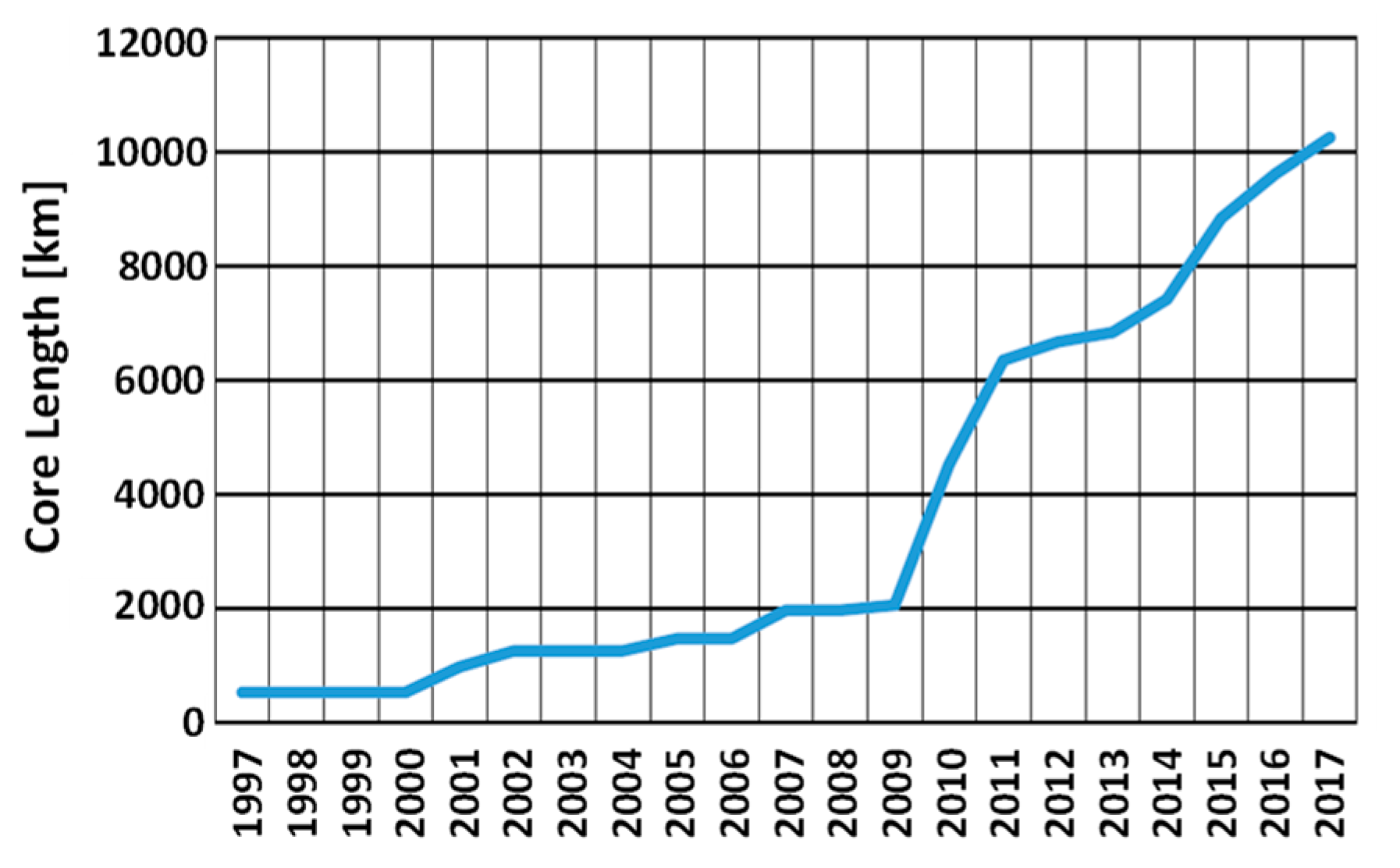
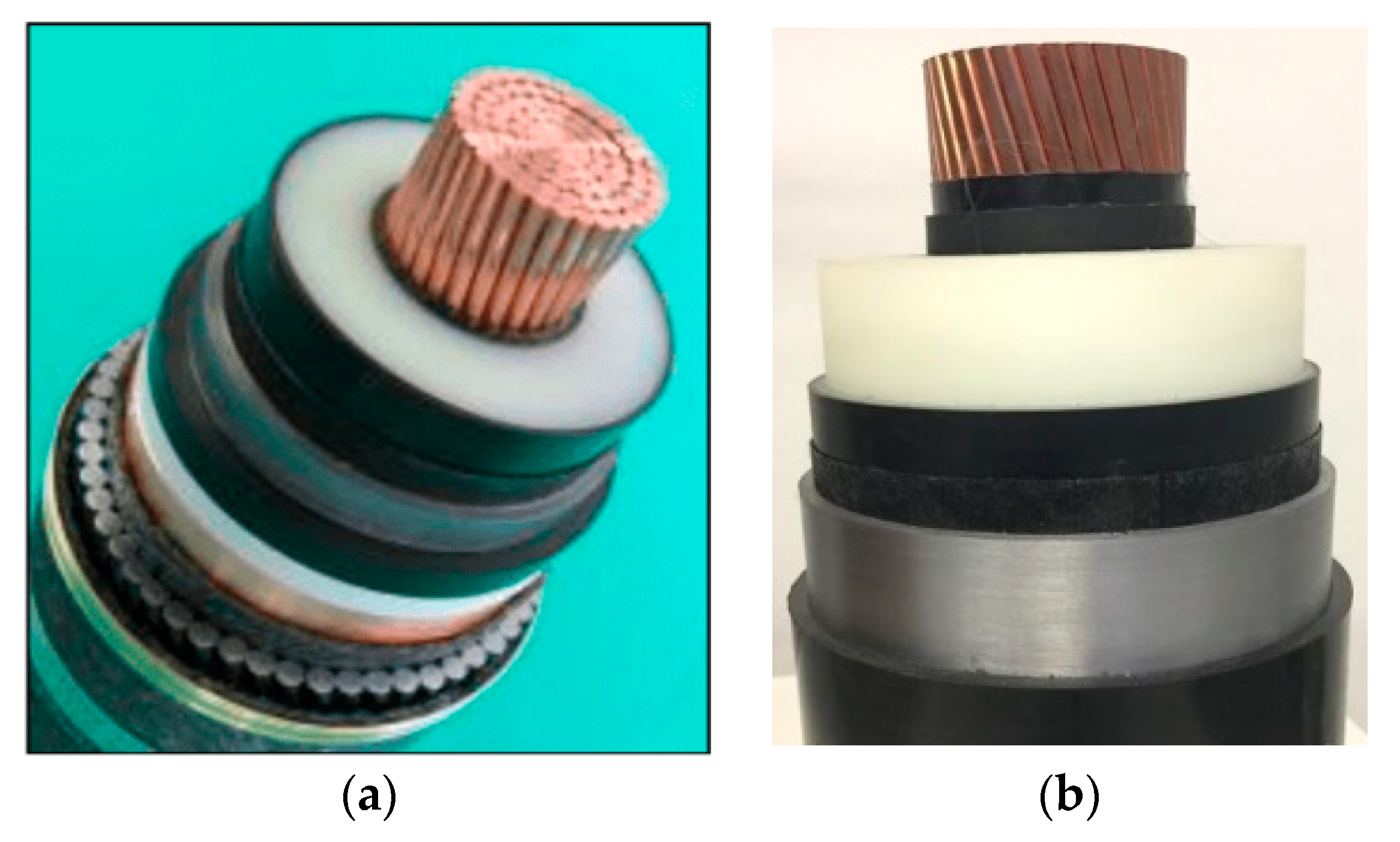
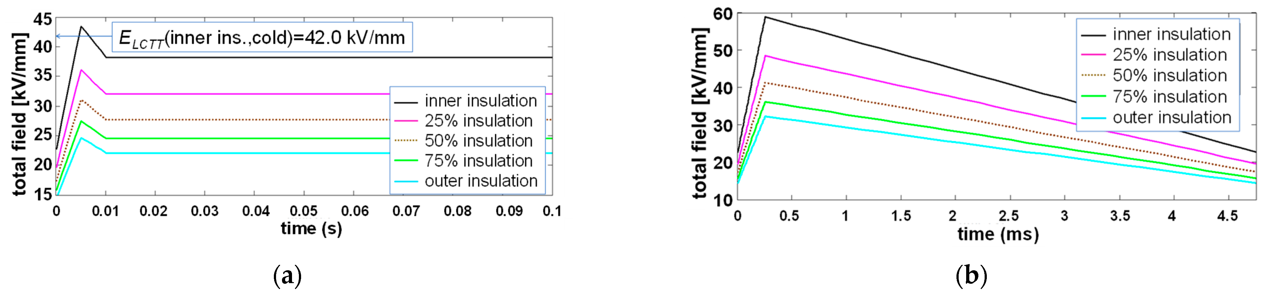
Table 1.
Alphabetical order list of topics/subtopics treated in the paper with the relevant Sections.
Table 1.
Alphabetical order list of topics/subtopics treated in the paper with the relevant Sections.
| Sect. | Topic | Sub-Topic | Keywords |
|---|---|---|---|
| 2 | Accessories | 2.1-Joints | flexible, premolded, interfaces, conductivity, SC, field grading |
| 2.2-Terminations | field grading, interfaces, pollution, fluids, porcelain, composite | ||
| 3 | Higher Voltage & Power | design, SC, extra-clean, degassing, nanofillers, semicons, PP | |
| 4 | Laying Environment | 4.1-Submarine Cables | mechan.stress, water tightness, fault location, electrodes, lead |
| 4.2-Underground Cables | joints, heat exchange, soil drying out, fault location, electrodes | ||
| 5 | Modelling | 5.1-Electric Field in Insulation | conductivity, Maxwell’s eqns., approximate field, SC, FEM |
| 5.2-Temperature in Insulation | Fourier eq., thermal network, transient temperature, FEM | ||
| 5.3-Insulation Life & Reliability | phenomen./phys. models, size effect, homogeneity, SC, PDs | ||
| 5.4-System Operation | converters, transients, AC grid interaction/stability, TOVs | ||
| 6 | Multiterminal HVDC | multiple interconnections, renewables, energy market | |
| 7 | Operation & Diagnostics | converter, transients, energy market, DTS, DAS, PD detection | |
| 8 | Recyclable Insulation | thermoplast., PP, no degassing, SC, manufacturing, eco-friend | |
| 9 | Space Charge Behavior | by-products, chemical/physical traps, semicons, PEA, TSM | |
| 10 | Testing | 10.1-HVDC Cable Test Setups | DC test, AC test, superimp.impulse test, PD meas., SC meas. |
| 10.2-R&D Testing Procedures | flat samples, minicables, prototypes, conductivity, SC, cycling | ||
| 10.3-New Test Techniques | PD measurements, SC measurements, IEEE Stds 1732, 2862 | ||
| 11 | Thermal Stability | Joule losses, dielectric losses, electr./therm. conductivity, soil | |
| 12 | Transient Voltages | 12.1-Long TOVs | VSC, pole-to-ground fault, symm. monopolar, rigid bipolar |
| 12.2-Superimposed Impulses | switching/lightning impulses, same/opposite polarity | ||
| 12.3-Voltage Polarity Reversals | fast/slow VPRs, relaxation, energy market, contingencies |
Main acronyms: DAS = distributed acoustic sensing; DTS = distributed temperature sensing; FEM = finite element method; LCC = line commutated converter; PD = partial discharge; PEA = pulse electro-acoustic; PP = polypropylene; SC = space charge; TOV = temporary overvoltage; TSM = thermal step method; VPR = voltage polarity reversal; VSC = voltage source converter.
Publisher’s Note: MDPI stays neutral with regard to jurisdictional claims in published maps and institutional affiliations. |
© 2021 by the author. Licensee MDPI, Basel, Switzerland. This article is an open access article distributed under the terms and conditions of the Creative Commons Attribution (CC BY) license (https://creativecommons.org/licenses/by/4.0/).
Share and Cite
MDPI and ACS Style
Mazzanti, G. Issues and Challenges for HVDC Extruded Cable Systems. Energies 2021, 14, 4504. https://doi.org/10.3390/en14154504
AMA Style
Mazzanti G. Issues and Challenges for HVDC Extruded Cable Systems. Energies. 2021; 14(15):4504. https://doi.org/10.3390/en14154504
Chicago/Turabian StyleMazzanti, Giovanni. 2021. "Issues and Challenges for HVDC Extruded Cable Systems" Energies 14, no. 15: 4504. https://doi.org/10.3390/en14154504
Note that from the first issue of 2016, this journal uses article numbers instead of page numbers. See further details here.