
Review of Wood Biomass Cyclone Burner

Department of Mechanical Engineering, Hanyang University ERICA Campus, 55 Hanyangdaehak-ro, Bldg 5, Sangnok-gu, Ansan 15588, Korea
Energies 2021, 14(16), 4807; https://doi.org/10.3390/en14164807
Submission received: 27 July 2021
/
Revised: 3 August 2021
/
Accepted: 5 August 2021
/
Published: 6 August 2021
(This article belongs to the Special Issue Integrated Waste Management)
Abstract
:Despite the technology for wood biomass combustion being much more advantageous when compared to traditional burners, such as the Stoker or fluidized burner, there has been scant research on the topic of wood biomass cyclone burners. The purpose of this paper is to review biomass cyclone burner technology, which includes theory, design, and combustion, in terms of the chemistry and properties of wood biomass, emission related to NOx and CO, and application of the burner, such as co-firing with coal and gasification firing. The design factors for type 2 cyclone burners have been identified through the following three dimensionless numbers: swirl intensity (S), Strouhal number (St), and Reynolds number (Re). The lowest CO and NOx of type 2 cyclone burners have been sought for pulverized and non-pulverized wood biomass. The benefits of the co-firing of wood biomass in a cyclone burner with coal, have been presented in respect to combustion efficiency, alkali retention, and the amount of K and Na. The results evidently reveal the reduction in clinker and slag generation, which are the biggest concern to wood biomass combustion. The recent results of gasification studies using type 2 cyclone burners are compared, in terms of producer gases and syngases (H2, CO, CO2, CH4).
1. Introduction
Biomass, predominantly wood biomass, is one the most important energy resources in the world. Traditionally, many developing countries in Africa, South America, and Asia have relied on wood biomass, as much as 19%, for their energy consumption [1]. Recently, the popularity of wood biomass has been spreading to developed countries in Europe and North America, taking up, on average, 3.5% of their total energy resources [1]. This evidently reflects the fact that wood biomass is a carbon-neutral energy source. Thanks to its photosynthetic reactions during the growth of wood, it takes CO2 from the atmosphere, while in parallel, its combustion produces the emission of greenhouse gases, such as CO2, back into the atmosphere. Compared to traditional fossil fuels, such as coal, wood biomass has the advantages of producing low ash, almost zero SOx, and no heavy metal substances [2]. However, in many cases, wood biomass combustion emits substantial amounts of NOx, especially fuel NOx, due to its intrinsic nitrogen contents. It is the conversion to PM (particulate matter) and the emission of particle dusts in the atmosphere that raises various environmental concerns, by communities across the world.
There are the following three different major methodologies for the conversion of wood biomass into energy: thermochemical, biological, or chemical processes. Their sub-categories are combustion, gasification, pyrolysis, anaerobic digestion, hydrolysis, fermentation, liquefaction, and esterification [3]. Among these sub-categories, combustion consists of almost 97% of the world’s bio-energy production [4]. Combustion technology has the following three distinguished sectors in the industry: fixed bed combustion with grate furnaces, fluidized bed combustion (FBC) with circulating fluidized beds (CFB) and bubbling fluidized beds (BFB), and pulverized fuel combustion with cyclone burners. The grate furnace is the most popular combustion technology in the industry, due to its flexibility of fuels and reliability, with easy operation. However, it suffers low combustion efficiency because of the high excess oxygen ratio (5–8%vol), and high CO and NOx emissions at the end. Typically, CFB/BFB technology has the superior feature of high combustion efficiency, and low NOx and CO emissions, compared to the grate furnace, on account of the low excess oxygen ratio (1–2% vol) [5]. The disadvantage of the CFB/BFB is the cost; it requires high investment and operation costs. The cyclone burner is located in the middle of these two combustion technologies. It has a comparatively low excess oxygen ratio (4–6%vol) and high NOx reduction, as a result of the efficient air mixing and staging [6]. Generally speaking, a negative aspect of the cyclone burner is its limit in size. In order to maintain proper air circulation for vortex generation, it cannot operate in a large system that the great furnace and CFB/BFB permits. One may find more information on wood biomass combustion for material properties, combustion behaviors, and ash behavior through other various authors [7,8,9,10].
Nevertheless, the cyclone burner has been used for a large coal-firing power plant in the United States, with the initiation of Bobcock and Wilcox (B&W). In the early 1940s, B&W invented a coal cyclone furnace for low-grade coal combustion. It burned bituminous, subbituminous, and lignite coal successfully, which could not have been used as a power plant fuel before. The coal cyclone furnace was very popular during the first oil shock period in the U.S., and it has expanded its applicable areas to other feedstock, such as wood biomass. Many studies for the coal cyclone furnace have been conducted in the areas of combustion and gasification [11,12,13,14,15,16], modelling and design [17,18,19,20,21], and emission and ash [22,23]. Compared to the coal cyclone furnace, there has been a lack of exploration on wood biomass cyclone burners. This paper will review biomass cyclone burner technology, including theory, design, and combustion, in terms of the chemistry and properties of wood biomass, emissions related to NOx and CO, and application of the burner, such as co-firing with coal and gasification firing.
2. Cyclone Burner Technology
Gupta et al. [24] conducted extensive research on cyclone-type combustor applications on small gas burners to big solid fuel furnaces. Gupta et al. surveyed and characterized the cyclone burner in five different categories, according to fuel, characteristics of flow, and geometry. Choe et al. [25] summarized five types of cyclone burners, as below (Table 1). Figure 1 shows a schematic diagram of the five types of cyclone burners. For biomass combustion, type 3 is used in some cases, but type 2 is mostly used with a variety of modifications along their fuel type and moisture contents. Most of them use pulverized fuel, except TSC (triple swirling combustor), presented by Choe et al. [25].
The advantages of cyclone burners can be summarized in the following four points: 1. long resident time, 2. flame stabilization by recirculation zone, 3. high combustion efficiency, due to the well mixing of fuel and air, and 4. low NOx and CO emission, due to the low combustion temperature and high combustion efficiency [24,25]. Choe et al. [32] explains that these technology features are basically a result of its strong swirl generation by the tangential inlet of air, and it creates toroidal recirculation in the middle of the combustion chamber before it would exit out. The following four main characteristics of the cyclone burner can be observed, due to its distinctive swirling effects: 1. rapid mixing of chemical species, 2. recirculation of heat, 3. high turbulent intensity of flow, and 4. long residence times (order of fifteen times longer, in terms of the average axial velocity in the chamber) [33]. All of these factors guarantee flame stability and an efficient burning process for the cyclone combustor [32].
Syred et al. [34] presented a non-dimensional swirl number as a design factor, with respect to the axial flux of angular momentum and liner momentum. Interestingly, it can be simplified with a geometry factor of the chamber under a uniform exit velocity and isothermal condition.
where,
- G∅ = axial flux of angular momentum;
- Gx = axial flux of linear momentum;
- De = exit diameter of chamber;
- Do = chamber diameter;
- At = cross sectional area of the tangential inlet.
For non-isothermal conditions [35], the following applies:
where,
- Ti = inlet gas temperature [Kelvin];
- To = outlet gas temperature [Kelvin].
For formation of the toroidal recirculation zone at the exit of the chamber, Syred et al. [34] calculated that the swirl number should be higher than 0.6, while the Reynolds number should be above 18,000.
In order to maintain the recirculation zone of the chamber, several design factors have been studied by multiple researchers. The geometry effects on swirl intensity have been deliberated by many authors [25,36,37,38,39]. Operating conditions, such as the velocity of air, feeder speed of fuel, and chamber temperature, were also identified in relationship with the swirl intensity, by Nemoda et al. [40] and Pasymi et al. [41]. Arnao et al. [37] and Pasymi et al. [42] studied the effects on the swirl flow, by mixing the intensity of fuel and combustion air, residence time of combustion, pressure drop in the chamber, and particle distribution of pulverized fuel. Pressure in the center of the recirculation zone should be maintained at a negative for a proper toroidal recirculation flow. Aydin et al. [43] and Gawali et al. [44] investigated the influence of static pressure change on the swirl flow. Additionally, simulation studies, based on numerical analysis on cyclone design with experimental verification, have been conducted by some scholars [45,46,47,48].
Chen et al. [47] introduced the initial tangential intensity (It) as a relative dimensionless number to the Swirl number, which is defined by flow rates and cross-sectional areas. This provides a practical way to understand the swirl flow with the velocity of combustion air.
where,
- = mass flow rate of the chamber;
- = mass flow rate of the tangential inlet;
- = cross sectional area of the chamber;
- = cross sectional area of the tangential inlet.
For the isothermal state type 2 cyclone burner, Styles et al. [49] discovered an important relationship between the following two dimensionless numbers: Strouhal number (St) and Reynolds number (Re) (Figure 2). They demonstrated how these two dimensionless numbers changed case by case, depending on the different number of inlets and different swirl numbers (S).
Choe et al. [25] utilized the results of Styles et al. [49] and found six design factors for their newly designed type 2 cyclone burner, called the TSC (three-way swirling combustor) burner. The six optimal design factors consist of the following three dimensionless numbers: swirl intensity (S: momentum factor), Strouhal number (St: frequency factor), and Reynolds number (Re: velocity factor), and the following three geometry factors: length or height of the chamber (L), exit diameter (De), and chamber diameter (Do). The results are shown below in Table 2. One may see more examples of design optimization by several researchers [30,35,36,37,38,42]. Table 2 displays the comparison of TSC with other type 2 cyclone burners.
3. Biomass Combustion with Cyclone Burner
The major combustion processes of wood biomass are drying, devolatilization, gasification, char combustion, and gas phase oxidation. Nussbaumer [50] explained the typical biomass combustion reaction with the following equations, where excess air ratio (λ) = amount of air supplied/stoichiometric amount of air.
CH1.44 O0.66 + λ 1.03 (O2 + 3.76 N2)
→ Intermediates (C, CO, H2, CO2, CmHn etc.)
→ CO2 + 0.72 H2O + (λ − 1) O2 + λ 3.87 N2 − 439 KJ/kmol
→ Intermediates (C, CO, H2, CO2, CmHn etc.)
→ CO2 + 0.72 H2O + (λ − 1) O2 + λ 3.87 N2 − 439 KJ/kmol
CH1.44 O0.66 represents the typical compositions of biomass that produce the following three kinds of pollutants after combustion: 1. uncombusted pollutants: CO, CXHY, PAH (polycyclic aromatic hydrocarbon), tar, soot, carbon, H2, HCN, NH3, and N2O; 2. pollutants from complete combustion: NOX (NO and NO2), CO2, and H2O; and 3. ash contaminants: ash particles (KCl, etc.), SO2, HCl, PCDD/F (polychlorinated dibenzo dioxin and furan), Cu, Pb, Zn, Cd, etc. [50].
Carbon monoxide emission is a barometer for complete combustion, and it is a function of the excess air ratio (λ) (Figure 3) [51]. Cyclone burners are under the same category of “d” in the graph named for automatic furnaces, developed with enhanced combustion technology. When compared to the old furnaces, “a”, “b”, and “c”, the modern automatic furnace “d”, including the cyclone burner, has a lower excess air ratio, with less CO production.
There are not many combustion experiment results available for wood biomass cyclone burners. Many of them focus more on gasification rather than on combustion only. Jenkins et al. [9] contributed interesting biomass combustion properties, and their effects on the rates of combustion and pollutant emissions. Their van Krevelen diagram, for the variable biomass and coal, provides fundamental data for wood biomass combustion studies (Figure 4). It demonstrates how much of the ratio of hydrogen-to-carbon (H/C) and oxygen-to-carbon (O/C) contributes to the heating value of fuels. The higher H/C ratio with the lower O/C ratio provides the higher heating value. This indicates that wood biomass has a higher H/C ratio and O/C ratio of about 75% and 300%, respectively, compared to coal. It also reveals that it has a lower heating value compared to coal, because of its relatively lower carbon content against hydrogen and oxygen. In biomass, the wood is closer to coal than the cellulose, while lignin is closer to coal than wood. In an investigation of the combustion kinetics of wood biomass, Yorulmaz et al. [52] measured the properties of various woods, including MDF, which is a waste wood (Table 3). In the proximate analysis, the amount of fixed carbon relates directly to the heating value, while the amount of C, O, and H relates to the heating value in the element analysis results.
Fungtammasan et al. [54] took the type 2 cyclone combustor and burned sawdust. They had two inlets, one for sawdust and air mixture injection, and the other for excess air ratio (λ) control. With a flow visualization technique, Fungtammasan et al. found the maximum for the combustion temperature, swirl number (S), and excess air ratio (λ). Luo et al. [5] also used a type 2 cyclone burner, and their fuel was a micron-sized biomass (less than 250 μm). They compared their cyclone burner with a fluidized bed combustor, which is also a floating combustion system that uses a sand medium. Luo et al. argued that cyclone combustion has the benefits of simpler configuration, easier operation, lower costs, and a wider selection of fuels. Choe et al. [25] introduced another type 2 cyclone burner, called the three-way swirling combustion (TSC) burner. Unlike other type 2 cyclone burners, Choe et al. used non-pulverized wood chips for their fuel, which meant their feeder was not an air blowing system, but rather acted as a screw feeder or a push feeder.
The results of the combustion of the three type 2 cyclone burners are presented below, in Table 4. On account of the micron-sized pulverized wood biomass, Fungtammasan et al. and Luo et al. reached about a 200 °C combustion temperature, which was higher than Choe et al. Choe et al. and Luo et al. had an ideal excess air ratio around 1.2, while Fungtammasan et al. had 1.5, with more combustion air consumption. Luo et al. and Choe et al.’s results for CO emissions along the excess air ratio matched well with Nussbaumer’s [50] report in Figure 3. The amount of NOx and SOx of Luo et al. was much higher than Choe et al.’s, most likely due to the higher combustion temperature and nature of fuel.
4. NOx Emission and Ash Deposit
In wood biomass combustion, the biggest complications for engineers are dealing with the formation of NOx, as a precursor for PM (particulate matter), and ash slagging, as a cause of clinker problems for boilers. Thermal NOx is formed at a temperature higher than 1300 °C, from nitrogen in the air, and prompt NOx is generated at a temperature higher than 1400 °C, from the combustion of the hydrocarbons of fuel, while fuel NOx is made at a temperature lower than 1300 °C, from the nitrogen in the fuel [51]. Since the wood biomass cyclone burner cannot typically reach 1300 °C, it usually only deals with fuel NOx. Nussbaumer [55] presented possible paths of fuel NOx formation from biomass combustion, stating that oxygen is a key parameter to convert fuel N to intermediate components, such as HCN and NHi. As a result of the strong swirling effects of the cyclone burner, a higher mixing ratio of the air brings more oxygen locally, and, unfortunately, it increases the fuel NOx. Mashmoudi et al. [56] reports that 20–40% of the nitrogen of fuel is converted to fuel NOx. Therefore, it is a challenge for the cyclone burner to reduce the fuel NOx significantly. However, the previous two cyclone burners (Luo et al. and Choe et al.) still presented much better emission gases of NOx and CO against the Stoker-type grate furnace, which is the most popular furnace in the waste treatment industry (Table 5).
As aforementioned, among inorganic contaminants, ash, as a deposit matter, is of the highest level of concern after wood biomass combustion, while NOx takes the lead in concern among pollutants from complete combustion. The ash from inorganic contaminants is composed mostly of bottom ash and flying ash generated by uncombusted pollutants. This is due to the ash of biomass in nature being more alkaline, and the cause of fouling and slagging is acid. Yi et al. [58] collected a useful index for ash behavior and deposition tendencies, for their co-firing study of cyclone burners. From Vamvuka et al.’s work [59], they used the base-to-acid ratio (Rb/a) for their biomass co-firing with coal study. The base-to-acid ratio indicates how much of the fuel is composed of acid components against a certain base line. The indexes are shown below.
Dayton et al. [60] and Miles et al. [61] studied the slugging and fouling tendency, in terms of the alkali index. They concluded that the base-to-acid ratio (Rb/a) of biomass is greater than one, while coal is less than one [62]. Their results indicate that the biomass, including wood, has a higher probability to form problematic deposits than coal. Table 6 shows the base-to-acid ratio along the ash chemical composition of the BMF (biomass micron fuel) and coal for co-firing with the same cyclone burner used by Luo et al. [5]. The calculation revealed that wood biomass (Rb/a = 3.28) has a stronger tendency of fouling/slagging generation than coal (Rb/a = 0.223). Therefore, a mix of coal and wood biomass for co-firing might decrease the chances of fouling and slagging in the boiler. However, if one wants a coal majority co-firing with wood biomass, this result should be understood in opposite terms, so that it limits the amount of biomass mix to as low as 10% [50].
One of the benefits of using a cyclone combustor is the separation or suspension of the problematic solid particles (e.g., ash), by a centrifugal force field. The type 2 cyclone has the same principle of physics as a cyclone dust/particle collector. This means that some of the flying ash can be moved down and collected at the bottom of the ash container. From previous studies, two sets of ash data are available for combustion of the wood biomass cyclone burner system. Luo et al. [5] reported 0.57% total ash, including 0.35% bottom ash and 0.22% flying ash from their micron-sized pulverized wood biomass combustion. Choe et al. [25] reported 1.4% ash in total, while the ash contents of the fuel, non-pulverized wood chips were 0.49%. They did not measure the bottom ash and flying ash separately; however, one may calculate their unburned particles as 0.91%. With fluidized bed combustion for wood powder, Paulrud et al. [63] measured that the ash contents of the micron-sized wood powder were 0.3–0.5% and the unburned matter was 0.43–0.64%. These ash results revealed that the floating combustion burner, including cyclone burners, had great combustion efficiency compared to others, such as the Stoker-type burners (see Table 5). The lower generation of ash in cyclone burners helps prevent clinker and slag formation at the wall of the chamber and the surface of the heat exchanger of the boiler. For a large boiler burning wood biomass, Vassilev et al. [64] presented NOx formation, while Mukunda et al. [65] presented ash deposit.
5. Co-Firing and Gasification of Cyclone Burner
Since wood biomass is considered a carbon neutral and eco-friendly fuel, lately it has been replacing some coal firing. Not only due to economic benefits, such as avoiding carbon taxes, but also because of some technical advantages, a full scale of wood biomass firing or co-firing for a coal majority, with a wood mixture of up to 20% [66], is increasing in practice. The most prominent reason for the co-firing of coal with biomass is to reduce emission gases, such as SOx, NOx, and fossil CO2. Depending on how it is ran, in some cases, boiler efficiency is improved as well [66]. In this paper, the co-firing of a wood biomass majority with a certain amount of coal mix has been the primary focus. As previously discussed, the ash deposits of wood biomass have a greater chance to generate slagging and fouling at the combustion chamber, or heat exchanger of the boiler. In order to reduce these emission gases, and prevent the generation of fouling/slagging, the processes of co-firing with coal (direct co-firing) and two stage combustion (gasification and combustion) have been studied for the last 20 years.
Nassubaumer [51] concisely explained the characteristics of the thermochemical conversion process of biomass. The amount of combustion air and temperature determine each of the following steps of the process: pyrolysis, gasification, and combustion (Table 7). Realistically, cyclone combustion is proceeded with an excess air ratio that is higher than 1.2, and a combustion temperature under 1300 °C. Gasification is a form of pyrolysis, with a higher temperature and more air for gas production, called “producer gases”, which is a mixture of CO, H2, and CH4, together with CO2 and N2 [3,66]. Through the gasification of the biomass, the solid fuel is converted to clean producer gases, and its combustion reduces emission gases and fouling/slagging together. Direct co-firing of wood biomass with coal also provides a similar effect of the reduction in ash and deposits, but moderately increases the amount of SOx and NOx.
Direct co-firing of biomass with coal provides several benefits, including the improvement of combustion efficiency, stability of combustion, reduction in CO, with a moderate increase in NOx, and the decrement in ash and deposit [64]. Yi et al. [58] conducted a combustion experiment of type 2 cyclone burners, with a change in the coal blend from 10% to 30%, and the change in excess air ratio (λ) from 0.96 to 1.26. Yi et al. used the combustion efficiency (η) equation below, simply in terms of carbon monoxide and carbon dioxide (Equation (6)). They also measured the temperature change and the efficiency change alongside the change in excess air ratio (λ). By Yi et al. [58], the results of excess air ratio (λ) versus temperature and combustion efficiency (η) are shown in Figure 5, and coal blend ratio versus NOx, SOx, and combustion efficiency (η) are shown in Figure 6. Figure 5 shows that the amount of CO is at its minimum and the combustion efficiency is at its maximum at excess air ratio (λ) = 1.26. In Figure 6, owing to the temperature increment that resulted from increasing the coal blend from 0% to 30%, the combustion efficiency increased from 95% to 98% with the NOx and SOx increment too. With the increment in coal blend ratio, they found that the base-to-acid ratio (Rb/a) decreased from 2.3 to 0.9. Zhang et al. [67] explained that the reason for the mitigation of fouling and slagging tendencies was due to the dilution and consumption of alkali metals via the interactions with sulfur or/and silica in the coal. Additionally, Demirbas [4,66] and Hughes [68] contributed to the discussion on wood biomass co-firing with coal blending, from the techniques, economics, and policy point of view.
For clean gas combustion, two-stage combustion has been applied for an extended period. The first air staging is an under-stoichiometric (λ < 1) process, to yield “producer gases”, such as CO, H2, CH4, CO2, N2, etc. The second fuel staging is an over-stoichiometric (λ > 1) process, to burn the “producer gases” completely. Wood biomass is devolatilized through the pyrolysis process under 300 °C, with no air, or a very small amount of air, which produces gases and char. With a little more air and an increase in the temperature, up to 800 °C, the char is gasified and produces more gases for the final stage of oxidization/combustion, which is conducted with a temperature higher than 800 °C and enough air (λ > 1). Nussbaumer [50] described this process succinctly and tangibly with a diagram show below (Figure 7). In many cases, the process of pyrolysis and gasification are merged together, so that there is no clear distinction between them.
Fredriksson [35] outlined his experiment for the two-stage cyclone gasifier and combustor with wood powder feedstock. For two-stage gasification and combustion, he modified a typical type 2 cyclone separator for his gasifier and had a separate combustor (Figure 8). The temperature for the gasifier was highest at the top, at 800–900 °C, and lowest at the bottom, at 500–600 °C, while wood powder accumulated. It did not have a clear distinction between the gasification and pyrolysis processes. The gases from the gasifier exited through the top of the cyclone gasifier and flew into the combustor for second stage combustion, where the temperature was higher than 900 °C. The char continued to release in the bottom exit. Fredriksson [35] used wood powder for fuel (HHV is about 20 MJ/kg) and got a comparatively low amount of syngas: 9% H2, 15.7% CO, and 2.4% CH4. The producer gases had less alkaline gases, which came from K and Na. The amount of K and Na decreased by 50% from 300 mg/kg at 800 °C, to 150 mg/kg at 920 °C [35]. Consequently, the gasification process actually reduced the possibilities of the slagging and fouling problem. Barnhart et al. [69] and Cousins [70] had different cyclone gasifier designs for different fuel power requirements.
Unlike Fredriksson, Syred et al. [71] used an inverted cyclone combustor for its “producer gases” generation. The temperature in the chamber varied from 900 °C at the bottom exit to 200 °C at the top. They proved that without any complex hot gas clean up, the producer gases are clean enough to directly fire into the secondary cyclone burner or the gas turbine. With a good-quality low caloric value gas, the cyclone burner produced a stable flow, with good mixing and burnout rates [71]. Further research on the gasification and combustion of wood biomass with cyclone burners, can be found in several studies [65,72,73,74,75,76,77,78]. The experimental results for the composition of producer gases (H2, CO, CO2, CH4, N2) were summarized with various wood biomass feedstock and seven different operating conditions, such as the fuel feed rate, syngas sampling time, particle size of feedstock, secondary air ratio to the total amount of air, syngas flow rate, and oxygen concentration (Table 8). The conversion rate of syngas (H2, CO, CO2, CH4), from the seven experiments of wood biomass, is a minimum of 28.29% to a maximum of 55.69%. This is a comparatively lower value than wet gasification methods, such as anaerobic digestion and hydrothermal gasification, which usually mark more than 90% of the syngas conversion rate. The main reason for the smaller conversion rate of syngas for the cyclone gasifier comes from the high nitrogen generation, 48% at the lowest to 68% at the highest. Among the seven gasification experiments for wood biomass feedstock, wood powder [65,71,76] and BMF [75,78] had higher conversion rates than sawdust [71] and furniture wood [77]. On the other hand, the caloric value of the producer gases varies from 0.78 MJ/m3 for sawdust to 6.2 MJ/m3 for BMF. This tells that, on average, the loss of heating value, through the gasification process, is up to approximately 70% or higher.
Even though the amount of syngas and its caloric value is comparatively low, its alkali retention capability is impressive. Fredriksson’s alkali retention in collected ash was at a maximum of 60% [35], compared to Syred et al.’s recorded 70%. This is a very promising result, because the gasification process contributes to lowering the possibility of fouling and slagging generation, which are the most negative aspects of wood biomass firing. With a fluidized bed system, Gabra et al. [72] reported a 12% retention rate for their bagasse gasification. In conclusion, the two-stage combustion of cyclone and the cyclone gasifier, did not show outstanding numbers for syngas generation compared to wet process gasification technologies; it successfully collected alkali and traces of heavy metals through its ash collection.
6. Conclusions
Wood biomass cyclone burners have a unique position against popular grate furnace and fluidized bed combustors, with respect to combustion efficiency, emission gases, renewable energy policy, and economy of the technology. For the combustion and gasification of wood biomass, the type 2 cyclone burner has been the top choice for researchers and the industry. Through literature studies, the following conclusions can be made for wood biomass cyclone burner technology:
- Design factors for the type 2 cyclone burner can be derived from the following three dimensionless numbers: swirl intensity (S), Strouhal number (St), and Reynolds number (Re). Critical design factors in the geometry of the combustor include the diameter of the chamber, longitudinal length or height of the chamber, and cross sectional area of the tangential inlet [25].
- At the excess air ratio (λ) = 1.2, the cyclone combustor acquired the minimum CO and NOx. With micron-sized pulverized wood (less than 250 μm), Luo et al. [5] obtained CO = 0.015 ppm and NOx = 182 ppm, while Choe [25] acquired 39 ppm and 49 ppm, respectively, for non-pulverized wood chips (about 5–10 cm size).
- The co-firing of wood biomass with coal (up to 30%) resulted in an increase in combustion efficiency, from 95% to 98%, and lowered the base-to-acid ratio (Rb/a), from 2.3 to 0.9 [58]. However, NOx and SOx moderately increased.
- Through the cyclone gasifier, the fine wood powder and BMF produced, on average, 44% syngas (H2, CO, CO2, CH4). Alkali retention in the collected ash was at a maximum of 70% by Syred et al. [71]. The amount of K and Na, the cause of fouling/slagging, decreased by 50%, from 300 mg/kg at 800 °C, to 150 mg/kg at 920 °C [35].
Due to its low production of syngas, the gasification by the cyclone burner is substandard when compared to other wet-based gasification technologies, such as the anaerobic digester and hydrothermal gasification. This is why the recent industry demands a move towards an all-in-one system of gasification and combustion together, using the type 2 cyclone burner, which has intrinsic benefits for this purpose. Due to the system’s cleaner flue gases and higher combustion efficiency, more R&D for a new all-in-one cyclone gasifier burner is expected in the near future, for various non-combustible feedstock, including high-moisture biomass, such as food waste, sewage sludge, and livestock manure.
Funding
This subject is supported by the Ministry of Environment as “Technology program for the Waste-to-Energy” (#2018001590002).
Conflicts of Interest
The authors declare no conflict of interest. The funders had no role in the design of the study; in the collection, analyses, or interpretation of data; in the writing of the manuscript, or in the decision to publish the results.
References
- The Handbook of Biomass Combustion & Co-Firing; Van Loo, S.; Koppejan, J. (Eds.) Earthscan: New York, NY, USA, 2008; Chapter 1. [Google Scholar]
- Klason, T.; Bai, X.-S. Computational study of the combustion process and NO formation in a small-scale wood pellet furnace. Fuel 2007, 86, 1465–1474. [Google Scholar] [CrossRef]
- Demirbas, A. Potential applications of renewable energy sources, biomass combustion problems in boiler power systems and combustion related environmental issues. Prog. Energy Combust. Sci. 2005, 31, 171–192. [Google Scholar] [CrossRef]
- Demirbas, A. Combustion characteristics of different biomass fuels. Prog. Energy Combust. Sci. 2004, 30, 219–230. [Google Scholar] [CrossRef]
- Luo, S.; Xiao, B.; Hu, Z.; Liu, S.; He, M. Experimental study on combustion of biomass micron fuel (BMF) in cyclone furnace. Energy Convers. Manag. 2010, 51, 2098–2102. [Google Scholar] [CrossRef]
- National Renewable Energy Laboratory; Sandia National Laboratory; University of California; Foster Wheeler Development Corporation; US Bureau of Mines; Miles, T.R. Alkali Deposits Found in Biomass Power Plants; Research Report NREL/TP-433-8142 SAND96-8225 Vols I and II.; National Renewable Energy Laboratory: Oakridge, TN, USA, 1996. [Google Scholar]
- Gaur, S.; Reed, T.B. An Atlas of Thermal Data for Biomass and Other Fuels; (No. NREL/TP-433-7965); National Renewable Energy Laboratory: Golden, CO, USA, 1995. [Google Scholar]
- Sander, B. Properties of Danish biofuels and the requirements for power production. Biomass Bioenergy 1997, 12, 177–183. [Google Scholar] [CrossRef]
- Jenkins, B.M.; Baxter, L.L.; Miles, T.R., Jr. Combustion properties of biomass. Fuel Process. Technol. 1998, 54, 17–46. [Google Scholar] [CrossRef]
- Skrifvars, B.-J.; Lauren, T.; Hupa, M.; Korbee, R.; Ljung, P. Ash behaviour in a pulverized wood fired boiler—A case study. Fuel 2004, 83, 371–1379. [Google Scholar] [CrossRef]
- Smoot, L.D.; Smith, P.J. Coal Combustion and Gasification; Plenum Press: New York, NY, USA, 1985. [Google Scholar]
- Xilin, W.; Zhanhua, M.; Dexin, W.; Lixing, Z. Experimental Study of Coal Combustion in an Improved Spouting-cyclone Combustor. Tsinghua Sci. Technol. 1998, 3, 959–962. [Google Scholar]
- Joo, N.R.; Kim, H.Y.; Chung, J.T.; Choi, S.I. The characteristics of pulverized coal combustion in the two stage cyclone combustor. KSME Int. J. 2002, 16, 1112–1120. [Google Scholar] [CrossRef]
- Osborne, D. The Coal Handbook: Towards Cleaner Production; Coal Utilisation; Woodhead Publishing Series in Energy: Oxford, UK, 2013; Volume 2. [Google Scholar]
- Zarzycki, R.; Bis, Z. Analysis of Coal Dust Combustion and Gasification in the Cyclone Furnace. In Proceedings of the E3S Web of Conferences 13, Cracow, Poland, 12–14 October 2016; p. 05003. [Google Scholar]
- Zarzycki, R. Pulverized Coal Gasification with Steam and Flue Gas. In Proceedings of the MATEC Web of Conferences 240, Cracow, Poland, 21–24 May 2018; p. 05036. [Google Scholar]
- Zhou, L.X.; Chen, T.; Xu, Y.; Ma, Z.H.; Guo, Y.C. Strongly swirling gas-particle flows and coal combustion in a cyclone combustor. Symp. Int. Combust. 1998, 27, 3119–3126. [Google Scholar] [CrossRef]
- Zarzycki, R.; Bis, Z. Modelling of Coal Dust Gasification in a Cyclone Furnace under Oxy-fuel Combustion Conditions. Procedia Eng. 2016, 157, 480–487. [Google Scholar] [CrossRef] [Green Version]
- Zarzycki, R.; Bis, Z.; Kobyłecki, R. The Concept of Coal Burning in a Cyclone Furnace. Procedia Eng. 2016, 157, 472–479. [Google Scholar] [CrossRef] [Green Version]
- Zarzycki, R.; Bis, Z. Modelling of the process of coal dust combustion in a cyclone furnace. J. Therm. Sci. 2017, 26, 192–198. [Google Scholar] [CrossRef]
- Zarzycki, R.; Jedras, J.; Kobyłecki, R. Fuel Processing in a Swirl Flow: Numerical Modelling of Combustion and Gasification. In Proceedings of the E3S Web of Conferences, Warsaw, Poland, 3–6 December 2019; Volume 137, p. 01052. [Google Scholar]
- Zarzycki, R. Swirl Chamber for Vitrification of Fly Ashes. In Proceedings of the E3S Web of Conferences 13, Cracow, Poland, 12–14 October 2016; p. 05004. [Google Scholar]
- Zarzycki, R.; Jędras, J.; Kobyłecki, R. Gasification of Coal Dust in a Cyclone Furnace in an O2/H2O Atmosphere. Energies 2020, 13, 2253. [Google Scholar] [CrossRef]
- Gupta, A.K.; Lilley, D.G.; Syred, N. Swirl Flows; Abacus Press: Kent, WA, USA, 1995; Chapter 5. [Google Scholar]
- Choe, K.; Lee, Y.; Lee, S.; Weedon, M. Experimental Study on Non-Pulverized Wood Biomass Combustion with a New Three-Way Swirling Combustion Cyclone Combustor. J. Therm. Sci. Eng. Appl. 2019, 12, 1–32. [Google Scholar] [CrossRef]
- Ustimenko, B.P.; Bukham, M.A. Turbulent flow structure in a cyclone chamber. Therm. Eng. 1968, 21, 64. [Google Scholar]
- Deissler, R.; Perlmutter, M. Analysis of the flow and energy separation in a turbulent vortex. Int. J. Heat Mass Transf. 1960, 1, 173–191. [Google Scholar] [CrossRef]
- Sibulkin, M. Unsteady, viscous, circular flow, part III. Application to the Ranque–Hilsch vortex tube. J. Fluid Mech. 1962, 12, 269–293. [Google Scholar] [CrossRef]
- Syred, N.; Dahmen, K.R.; Styles, A.C.; Najim, S.A. Review of combustion problems associated with low calorific value gases. J. Inst. Energy 1997, 50, 195–207. [Google Scholar]
- Crowe, C.T. Conservation equations for vapor-droplet flows. In Proceedings of the Heat Transfer and Fluid Mechanics Institute Meeting 25th, Davis, CA, USA, 21–23 June 1976; (A76-35401 17-34). Stanford University Press: Stanford, CA, USA, 1976; pp. 214–228. [Google Scholar]
- Weller, A.E.; Dennis, W.R.; Putnam, A.A. The Development of a Surface Hardening Burner with a High Rate of Heat Transfer Resulting from a Self Generating Oscillation; Final Battelle Report; Cincinnati Milling Machine Company: Cincinnati, OH, USA, 1955. [Google Scholar]
- Choe, K.; Chae, J.; Cheah, W.; Na, S. A New Three-Way Swirling Combustion Technology with Air Curtain Insulation Effect for Solid Waste. J. Therm. Sci. Eng. Appl. 2018, 10, 041021. [Google Scholar] [CrossRef]
- Smith, J.L. An Experimental Study of the Vortex in the Cyclone Separator. J. Basic Eng. 1962, 84, 602–608. [Google Scholar] [CrossRef]
- Syred, N.; Beér, J. Combustion in swirling flows: A review. Combust. Flame 1974, 23, 143–201. [Google Scholar] [CrossRef]
- Fredriksson, C. Exploratory Experimental and Theoretical Studies of Cyclone Gasification of Wood Powder. Ph.D. Thesis, Lulea University of Technology, Luleå, Sweden, 2003. [Google Scholar]
- Bourgouin, J.F.; Moeck, J.; Durox, D.; Schuller, T.; Candel, S. Sensitivity of swirling flows to small changes in the swirler geometry. Comptes Rendus Mec. 2013, 341, 211–219. [Google Scholar] [CrossRef]
- Sosa-Arnao, J.H.; Ferreira, D.J.O.; Santos, C.G.; Justo, E.; Alvarez, J.E.; Rangel, L.P.; Park, S.W. The Influence of Swirl Burner Geometry on the Sugar-Cane Bagasse Injection and Burning. Technol. Int. J. Mech. Aerosp. Ind. Mechatron. Manuf. Eng. 2015, 9, 798–801. [Google Scholar]
- Ziqiang, L.; Guangqiang, L.; Yingjie, L. Optimization Study on Bias Angle of a Swirl Burner with Tangential Inlet Air. Int. J. Smart Home 2016, 10, 171–180. [Google Scholar] [CrossRef]
- Pasymi, P.; Budhi, Y.W.; Bindar, Y. Experimental and Numerical Investigations of Fluid Flow Behaviors in a Biomass Cyclone Burner. ASEAN J. Chem. Eng. 2020, 20, 88–98. [Google Scholar] [CrossRef]
- Nemoda, S.; Bakić, V.; Oka, S.; Zivković, G.; Crnomarkovic, N. Experimental and numerical investigation of gaseous fuel combustion in swirl chamber. Int. J. Heat Mass Transf. 2005, 48, 4623–4632. [Google Scholar] [CrossRef]
- Pasymi, P.; Budhi, Y.W.; Bindar, Y. Effect of initial tangential intensity on the fluid dynamic characteristics in tangential burner. MATEC Web. Conf. 2017, 101, 03001. [Google Scholar] [CrossRef] [Green Version]
- Pasymi, P.; Budhi, Y.W.; Bindar, Y. Three dimensional cyclonic turbulent flow structures at various geometries, inlet-outlet orientations, and operating conditions. J. Mech. Eng. Sci. 2018, 12, 4300–4328. [Google Scholar] [CrossRef]
- Aydin, O.; Avci, M.; Markal, B.; Yazici, M.Y. An experimental study on the decaying swirl flow in a tube. Int. Commun. Heat Mass Transf. 2014, 55, 22–28. [Google Scholar] [CrossRef]
- Gawali, S.S.; Bhambere, M.B. Computational fluid dynamics approach for predictions of cyclone separator pressure drop. Int. J. Mech. Eng. Robot. Res. 2015, 4, 374–377. [Google Scholar]
- Syred, N.; Fick, W.; O’Doherty, T.; Griffiths, A.J. The Effect of the Processing Vortex Core on Combustion in a Swirl Number. Combust. Sci. Technol. 1997, 125, 139–157. [Google Scholar] [CrossRef]
- Chen, J.; Haynes, B.S.; Fletcher, D.F.A. Numerical and experimental study of tangentially injected swirling pipe flows. In Proceedings of the 2nd International Conference on CFD in the Minerals and Process Industries CSIRO, Melbourne, Australia, 6–8 December 1999; pp. 485–490. [Google Scholar]
- De Bruyn Kops, S.M.; Malte, P.C. Simulation and Modeling of Wood Dust Combustion in Cyclone Burners. Available online: http://faculty.washington.edu/malte/OldSite/pubs/final_report_wood_dust_combustion_in_cyclone_burners.pdf (accessed on 1 April 2021).
- Al-Abdeli, Y.M.; Masri, A.R. Review of laboratory swirl burners and experiments for model validation. Exp. Therm. Fluid Sci. 2015, 69, 178–196. [Google Scholar] [CrossRef]
- Styles, A.C.; Syred, N.; Najim, S.E. Stabilization of Low Calorific Value Gases in a Cyclone Combustor. J. Energy 1981, 5, 159. [Google Scholar]
- Nussbaumer, T. Biomass Combustion in Europe Overview on Technologies and Regulations; Final Report 08–03; New York State Energy Research and Development Authority: Albany, NY, USA, 2008. [Google Scholar]
- Nussbaumer, T. Furnace Design and Combustion Control to Reduce Emissions and Avoid Ash Slagging; R&D Report. 1997. Available online: https://silo.tips/download/furnace-design-and-combustion-control-to-reduce-emissions-and-avoid-ash-siagging (accessed on 1 April 2021).
- Yorulmaz, S.Y.; Atimtay, A.T. Investigation of combustion kinetics of treated and untreated waste wood samples with thermogravimetric analysis. Fuel Process. Technol. 2009, 90, 939–946. [Google Scholar] [CrossRef]
- Baxter, L. Ash deposition during biomass and coal combustion: A mechanistic approach. Biomass Bioenergy 1993, 4, 85–102. [Google Scholar] [CrossRef]
- Fungtammasan, B.; Jittrepit, P. An Experimental Study on the Combustion Characteristics of Sawdust in a Cyclone Combustor. In The Journal of KMUTNB; King Mongkut’s University of Technology: North Bangkok, Thailand, 2008. [Google Scholar]
- Nussbaumer, T. Combustion and Co-combustion of Biomass: Fundamentals, Technologies, and Primary Measures for Emission Reduction. Energy Fuels 2003, 17, 1510–1521. [Google Scholar] [CrossRef]
- Mahmoudi, S.; Baeyens, J.; Seville, J.P. NOx formation and selective non-catalytic reduction (SNCR) in a fluidized bed combustor of biomass. Biomass Bioenergy 2010, 34, 1393–1409. [Google Scholar] [CrossRef]
- Seo, Y. Study of Characteristics of Emission Gases from Waste Wood; R&D Report; National Institute of Environmental Research: Incheon, Korean, 2008. [Google Scholar]
- Yi, Q.; Qi, F.; Xioa, B.; Hu, Z.; Liu, S. Co-firing ramie residue with supplementary coal in a cy-clone furnace. Bio Resour. 2013, 8, 844–854. [Google Scholar]
- Vamvuka, D.; Kakaras, E. Ash properties and environmental impact of various biomass and coal fuels and their blends. Fuel Process. Technol. 2011, 92, 570–581. [Google Scholar] [CrossRef]
- Dayton, D.; Jenkins, B.; Turn, S.Q.; Bakker, R.R.; Williams, R.B.; Belle-Oudry, A.D.; Hill†, L.M. Release of Inorganic Constituents from Leached Biomass during Thermal Conversion. Energy Fuels 1999, 13, 860–870. [Google Scholar] [CrossRef]
- Miles, T.R.; Miles, T.R., Jr.; Baxter, L.L.; Bryers, R.W.; Jenkins, B.M.; Oden, L.L. Boiler deposits from firing biomass fuels. Biomass Bioenergy 1996, 10, 125–138. [Google Scholar] [CrossRef]
- Tillman, D.A. Biomass cofiring: The technology, the experience, the combustion consequences. Biomass Bioenergy 2000, 19, 365–384. [Google Scholar] [CrossRef]
- Paulrud, S.; Nilsson, C. The effects of particle characteristics on emissions from burning wood fuel powder. Fuel 2004, 83, 813–821. [Google Scholar] [CrossRef]
- Vassilev, S.V.; Vassileva, C.G.; Vassilev, V.S. Advantages and disadvantages of composition and properties of biomass in comparison with coal: An overview. Fuel 2015, 158, 330–350. [Google Scholar] [CrossRef]
- Mukunda, H.; Dasappa, S.; Paul, P.; Rajan, N.; Shrinivasa, U. Gasifiers and combustors for biomass—Technology and field studies. Energy Sustain. Dev. 1994, 1, 27–38. [Google Scholar] [CrossRef]
- Demirbaş, A. Sustainable cofiring of biomass with coal. Energy Convers. Manag. 2003, 44, 1465–1479. [Google Scholar] [CrossRef]
- Zhang, L.; Xu, C.; Champagne, P. Overview of recent advances in thermo-chemical conversion of biomass. Energy Convers. Manag. 2010, 51, 969–982. [Google Scholar] [CrossRef]
- Hughes, E. Biomass cofiring: Economics, policy and opportunities. Biomass Bioenergy 2000, 19, 457–465. [Google Scholar] [CrossRef]
- Banhart, J.S.; Laurendeau, N.M. Pulverised coal combustion and gasification in a cyclone reactor. Ind. Eng. Chem. Process. Des. Dev. 1982, 21, 671–680. [Google Scholar] [CrossRef]
- Cousins, J.W.; Robinson, W.H. Gasification of sawdust in an air-blown cyclone gasifier. Ind. Eng. Chem. Process. Des. Dev. 1985, 24, 1281–1287. [Google Scholar] [CrossRef]
- Syred, C.; Fick, W.; Griffiths, A.; Syred, N. Cyclone gasifier and cyclone combustor for the use of biomass derived gas in the operation of a small gas turbine in cogeneration plants. Fuel 2004, 83, 2381–2392. [Google Scholar] [CrossRef]
- Gabra, M.; Nordin, A.; Ohman, M.; Kjellstrom, B. Alkali retention/separation during bagasse gasification: A comparison between a fluidized bed and a cyclone gasifier. Biomass Bioenergy 2001, 21, 461–476. [Google Scholar] [CrossRef]
- Demirbaş, A. Yields of hydrogen-rich gaseous products via pyrolysis from selected biomass samples. Fuel 2001, 80, 1885–1891. [Google Scholar] [CrossRef]
- Morf, P.; Hasler, P.; Nussbaumer, T. Mechanisms and kinetics of homogeneous secondary reactions of tar from continuous pyrolysis of wood chips. Fuel 2002, 81, 843–853. [Google Scholar] [CrossRef]
- Guoa, X.; Xiaoa, B.; Liua, S.; Hu, Z.; Luo, S.; He, M. An experimental study on air gasification of biomass micron fuel (BMF) in a cyclone gasifier. Int. J. Hydrog. Energy 2009, 34, 1265–1269. [Google Scholar] [CrossRef]
- Sun, S.; Zhao, Y.; Tian, H.; Ling, F.; Su, F. Experimental study on cyclone air gasification of wood powder. Bioresour. Technol. 2009, 100, 4047–4049. [Google Scholar] [CrossRef]
- Al-Attab, K.; Zainal, Z.; Alattab, K. Syngas production and combustion characteristics in a biomass fixed bed gasifier with cyclone combustor. Appl. Therm. Eng. 2017, 113, 714–721. [Google Scholar] [CrossRef]
- Cheng, G.; He, P.-W.; Xiao, B.; Hu, Z.-Q.; Liu, S.-M.; Zhang, L.-G.; Cai, L. Gasification of biomass micron fuel with oxygen-enriched air: Thermogravimetric analysis and gasification in a cyclone furnace. Energy 2012, 43, 329–333. [Google Scholar] [CrossRef]
Figure 1.
Schematic diagram of five types of cyclone burners [24]. Note: De = exit diameter of chamber, Di = inlet diameter of chamber, Do = chamber diameter, L = longitudinal length of chamber.
Figure 1.
Schematic diagram of five types of cyclone burners [24]. Note: De = exit diameter of chamber, Di = inlet diameter of chamber, Do = chamber diameter, L = longitudinal length of chamber.

Figure 2.
Variation in Strouhal number () and Reynolds number (Re) by the number of inlets and swirl intensity (S) under isothermal state [49]. Note: f = frequency of vortex shedding, Q = volumetric flow rate, De = exit diameter of chamber.
Figure 2.
Variation in Strouhal number () and Reynolds number (Re) by the number of inlets and swirl intensity (S) under isothermal state [49]. Note: f = frequency of vortex shedding, Q = volumetric flow rate, De = exit diameter of chamber.
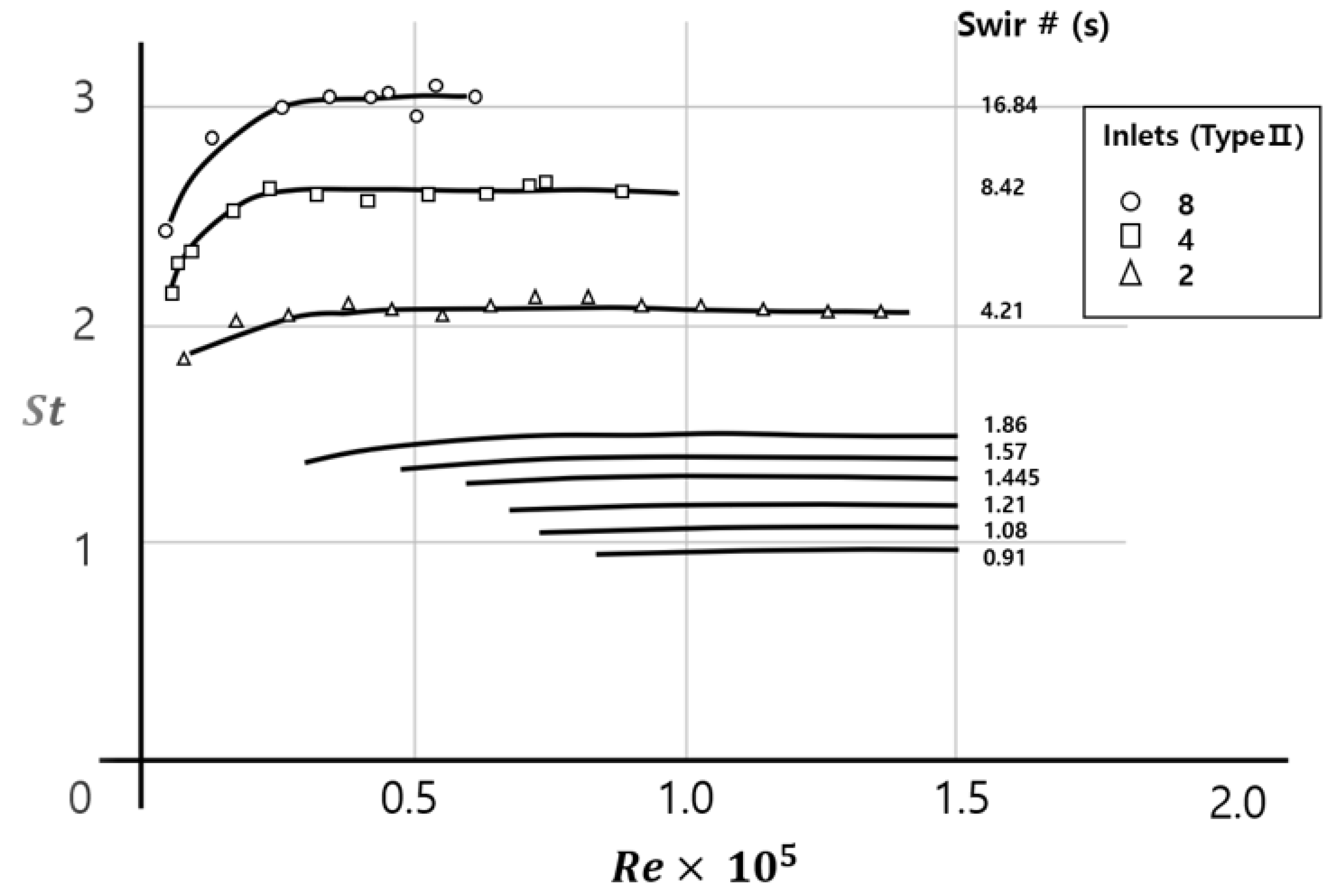
Figure 3.
Carbon monoxide emission as a function of the excess air ratio (λ) [51]. Note: (a) simple manually charged log wood boiler, (b) downdraft boiler tor log wood, (c) automatic furnace with combustion technology (as of 1990), (d) automatic furnace with enhanced combustion technology (as of 1995). Note: excess air ratio (λ) = the total amount of air used in the combustion/the amount of stoichiometric air.
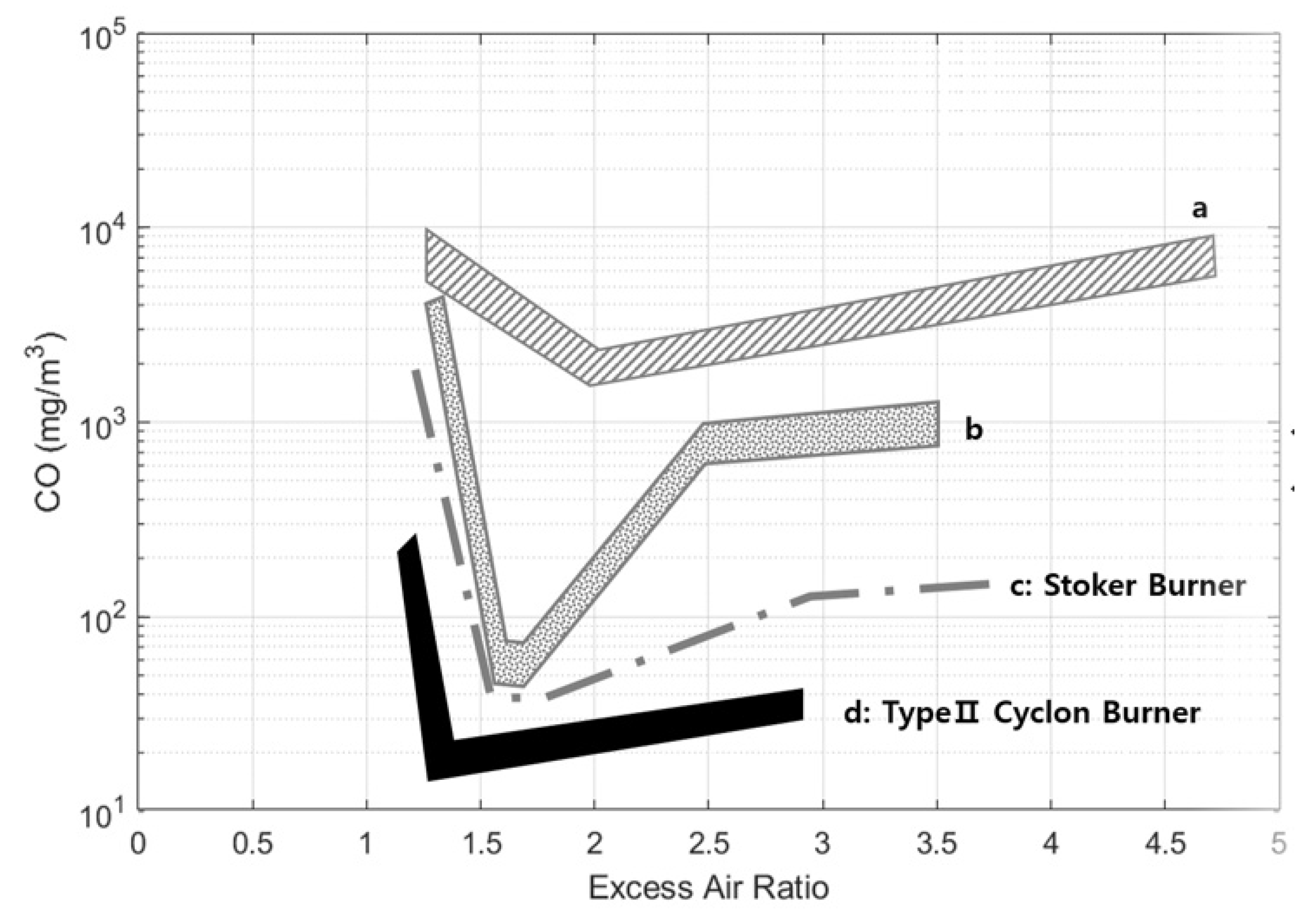
Figure 4.
The van Krevelen diagram for coalification, showing the difference of various biomasses and coal in terms of oxygen and hydrogen ratio to carbon [53].
Figure 4.
The van Krevelen diagram for coalification, showing the difference of various biomasses and coal in terms of oxygen and hydrogen ratio to carbon [53].
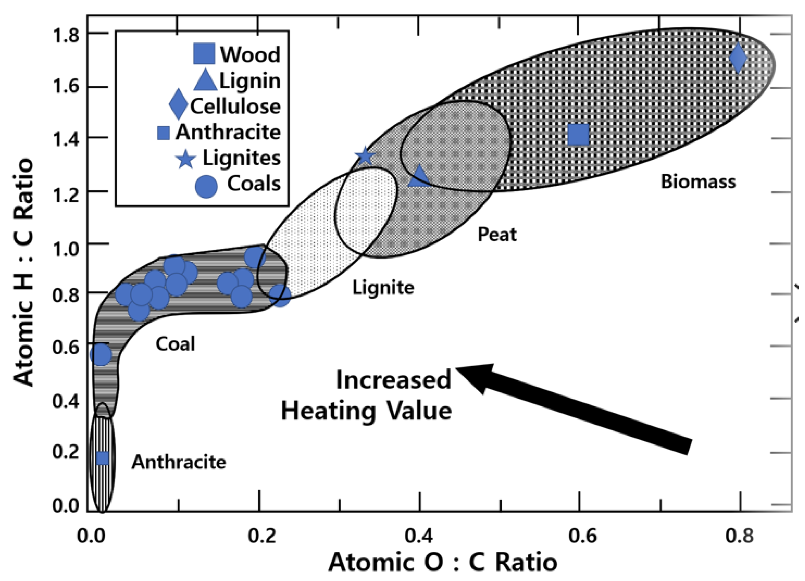
Figure 5.
Effect of excess air ratio on combustion temperature and combustion efficiency for pure biomass [58].
Figure 5.
Effect of excess air ratio on combustion temperature and combustion efficiency for pure biomass [58].
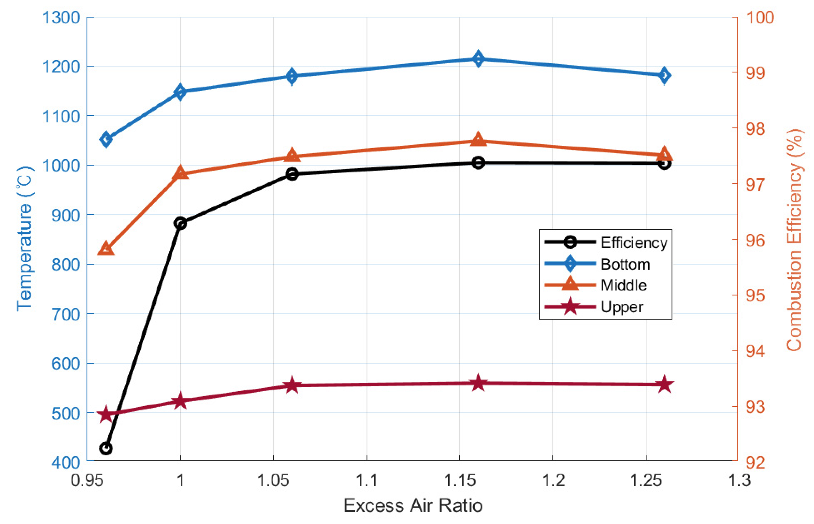
Figure 6.
Effect of coal blend ratio on SOx and NOx, combustion efficiency for excess air ratio (λ) = 1.16 [58].
Figure 6.
Effect of coal blend ratio on SOx and NOx, combustion efficiency for excess air ratio (λ) = 1.16 [58].
Figure 7.
Process diagram for two-stage combustion (gasification and combustion) of biomass producer gases of each step [50].
Figure 7.
Process diagram for two-stage combustion (gasification and combustion) of biomass producer gases of each step [50].
Figure 8.
Type 2 cyclone gasifier with a separate combustor, and its air movement [35].
Figure 8.
Type 2 cyclone gasifier with a separate combustor, and its air movement [35].

Table 1.
Five types of cyclone combustors categorized by Gupta et al. [24,25] Note: De = exit diameter of chamber. Do = chamber diameter, L = longitudinal length of chamber.
| Cyclone Type | S (Swirl #) | De/Do | L/De | Fuel | Configuration |
|---|---|---|---|---|---|
| Type1 [26] | 2–11 | 0.4–0.7 | 1–3 | High calorific value and high volatile | Bottom exit |
| Type2 [27,28] | 8–20 | 0.4–0.5 | 1–1.25 | High ash | Top exit/ash through bottom exit |
| Type3 [29] | 3 or higher | 0.3 or less | 5 or higher | Low calorific and high volatile | Horizontal multi-inlets |
| Type4 [30] | 3 or higher | About 0.4 | About 3 | Oil (sulfuric) | Top inlet/bottom exit |
| Type5 [31] | 3 or less | 0.4–0.6 | 2.2–2.9 | Metal | Top exit |
Table 2.
Design criteria of TSC cyclone combustor compared with other type 2 cyclone burners.
| S | L/Do | De/Do | St [41] | Re @Max. St [41] | |
|---|---|---|---|---|---|
| TSC [25] | 14.53 | 1.9 | 0.54 | 2.93 | 0.347 × 10⁵ |
| Mildsteel Combustor [46] | 6.8 | 2.0 | 0.44 | - | - |
| Perpex Model [46] | 8.8 | 2.06 | 0.51 | - | |
| Type 2 Cyclone [41] | ≤20 | ≤4 | ≥0.4, ≤0.5 | ≤3 | - |
Table 3.
Wood biomass element analysis and approximate analysis [52] Note 1: MDF stands for medium density fireboard. Note 2: all units are % by weight except the calorific value.
Table 3.
Wood biomass element analysis and approximate analysis [52] Note 1: MDF stands for medium density fireboard. Note 2: all units are % by weight except the calorific value.
| Sample | Volatile Matter | Ash | Fixed Carbon | Calorific Value (MJ/kg) | C | H | N | O | S |
|---|---|---|---|---|---|---|---|---|---|
| Pine | 88.02 | 0.62 | 11.29 | 19.72 | 53.28 | 6.35 | 0.16 | 40.21 | - |
| MDF | 86.68 | 2.29 | 11.06 | 19.31 | 49.57 | 6.33 | 4.44 | 39.66 | - |
| Paticleboard | 83.82 | 1.22 | 14.38 | 17.51 | 46.26 | 5.83 | 2.36 | 45.51 | 0.04 |
| Plywood | 85.79 | 0.80 | 13.40 | 18.64 | 47.12 | 5.92 | 1.19 | 45.72 | 0.05 |
Table 4.
Comparison of the three type 2 wood biomass cyclone burners in terms of temperature, emission gases, and excess air ratio (λ).
Table 4.
Comparison of the three type 2 wood biomass cyclone burners in terms of temperature, emission gases, and excess air ratio (λ).
| Fuel Type | Max. Temp (°C) | O2 (%) | CO (ppm) | NOx (ppm) | SOx (ppm) | Excess Air Ratio (λ) | |
|---|---|---|---|---|---|---|---|
| Fungtammasan et al. [54] | Sawdust | 1275 | - | 3196 | - | - | 1.50 |
| Luo et al. [5] | Micron-sized wood (less than 250 μm) | 1270 | 0.6 | 0.015 | 182.0 | 96.0 | 1.20 |
| Choe et al. [25] | Non-pulverized wood chips (5–10 cm) | 1058 | 3.53 | 39.46 | 48.67 | 0.3 | 1.21 |
Table 5.
Comparison of NOx and CO between cyclone burners (Luo et al. and Choe et al.) and other wood biomass combustion by Stoker-type furnaces.
Table 5.
Comparison of NOx and CO between cyclone burners (Luo et al. and Choe et al.) and other wood biomass combustion by Stoker-type furnaces.
| Construction Waste [1] | Non-MDF [57] | MDF [57] | Antisepsis Wood [57] | Wood [1] | Luo et al. [5] | Choe et al. [25] | |
|---|---|---|---|---|---|---|---|
| NOx (ppm) | 176 | 480 | 681 | 603 | 125–261 | 182 | 49 |
| CO (ppm) | 4243 | 2673 | 5480 | 12,628 | 96–1547 | 0.015 | 39 |
Table 6.
The base-to-acid ratio (Rb/a) with the ash chemical composition of the BMF (biomass micron fuel) and coal used for co-firing of cyclone burner [59].
Table 6.
The base-to-acid ratio (Rb/a) with the ash chemical composition of the BMF (biomass micron fuel) and coal used for co-firing of cyclone burner [59].
| Components (%) | SiO2 | Al2O3 | Fe2O3 | MgO | K2O | Na2O | CaO | P2O5 | SO3 | TiO2 | Rb/a |
|---|---|---|---|---|---|---|---|---|---|---|---|
| BMF | 14.28 | 3.16 | 2.38 | 7.14 | 8.10 | 6.40 | 42.82 | 4.80 | 2.91 | 2.91 | 3.28 |
| Coal | 45.58 | 30.02 | 9.69 | - | 2.02 | - | 5.48 | 0.85 | 4.34 | 1.64 | 0.223 |
Table 7.
Characteristics of the following thermochemical conversion processes of biomass: combustion, gasification, and pyrolysis [51].
Table 7.
Characteristics of the following thermochemical conversion processes of biomass: combustion, gasification, and pyrolysis [51].
| Process | Excess Air Ratio (λ) | Temperature (°C) | Main Product |
|---|---|---|---|
| Combustion | >1 | 800–1300 | Hot exhaust gas |
| Gasification | 0.2 < λ < 0.5 | 700–900 | Producer gas of high thermal value |
| Pyrolysis | 0 < λ < 0.2 | 400–700 | Liquid of high thermal value (pyrolysis oil) |
Table 8.
Producer (exhaust) gases’ compositions by different wood biomass along different operating conditions.
Table 8.
Producer (exhaust) gases’ compositions by different wood biomass along different operating conditions.
| Wood Powder [71] | Sawdust [71] | Powdery Biomass [65] | BMF (2) [75] | Wood Powder [76] | Furniture Wood [77] | BMF (2) [78] | ||||||||||||||||
|---|---|---|---|---|---|---|---|---|---|---|---|---|---|---|---|---|---|---|---|---|---|---|
| Operating Conditions | Feed Rate (kg/h) | Sampling Time (Min) | Particle Size (mesh) | Secondary Air Ratio (%) (1) | Syngas Flow Rate (m3/h) | Oxygen Concentration (vol %) | ||||||||||||||||
| 26 | 40 | 28 | 40 | 59 | 200 | 404 | 60–100 | 100–180 | <180 | 19 | 23 | 31 | 50 | 100 | 150 | 200 | 21 | 23 | 25 | 28 | 31 | |
| Temperature (°C) | 818 | 842 | 819 | 915 | 650–700 | 755 | 790 | 814 | 850–1000 | 310 | 450 | 550 | 620 | 798 | 803 | 820 | 838 | 845 | ||||
| H2 (%, v/v) | 9.06 | 8.56 | 3.71 | 7.14 | 16.51 | 16.84 | 18.72 | 4.77 | 6.92 | 8.26 | 5.03 | 7.10 | 6.00 | 12.30 | 11.10 | 11.50 | 11.20 | 8.83 | 9.84 | 11.27 | 11.95 | 12.01 |
| O2 (%, v/v) | 1.17 | 1.48 | 1.97 | 1.69 | NA | NA | NA | NA | NA | NA | NA | NA | NA | 1.80 | 1.20 | 2.30 | 3.00 | NA | NA | NA | NA | NA |
| N2 (%, v/v) | 56.87 | 52.09 | 68.34 | 60.33 | 49.23 | 60.55 | 48.62 | NA | NA | NA | NA | NA | NA | 52.90 | 54.30 | 52.90 | 58.40 | NA | NA | NA | NA | NA |
| CH4 (%, v/v) | 1.95 | 3.31 | 1.06 | 1.95 | 0.69 | 0.64 | 1.29 | 2.42 | 1.94 | 1.58 | 3.84 | 3.22 | 4.47 | 2.40 | 1.40 | 1.40 | 1.00 | 2.96 | 3.41 | 3.85 | 4.44 | 4.66 |
| CO (%, v/v) | 15.37 | 18.18 | 7.05 | 12.08 | 10.44 | 19.39 | 19.79 | 17.27 | 18.95 | 19.29 | 18.60 | 22.00 | 20.50 | 15.00 | 20.00 | 18.00 | 15.40 | 18.08 | 20.98 | 22.17 | 24.01 | 23.93 |
| CO2 (%, v/v) | 13.39 | 12.63 | 16.47 | 14.55 | 9.95 | 10.97 | 12.07 | 12.14 | 13.57 | 13.82 | 16.01 | 18.01 | 15.81 | 15.60 | 12.00 | 13.90 | 11.00 | 9.41 | 10.94 | 12.51 | 14.54 | 15.09 |
| SO2 (mg/m) | 4.40 | 3.10 | 1.60 | 3.80 | NA | NA | NA | NA | NA | NA | NA | NA | NA | NA | NA | NA | NA | NA | NA | NA | NA | NA |
| Calorific Value of Exhaust gas (MJ/m3)/(MJ/kg) | 4.26 | 5.91 | 0.78 (3) | 2.99 (4) | 4.16 | 4.25 | 4.50 | 4.08 | 4.22 | 4.25 | 4.57 | 5.67 | 5.22 | 4.40 | 4.50 | 4.30 | 3.75 | 4.38 | 4.93 | 5.39 | 5.91 | 6.20 |
| Syngases (H2, CH4, CO, CO2) Conversion Rate (%, v/v) | 39.77 | 42.68 | 28.29 | 35.72 | 37.59 | 47.84 | 51.87 | 36.60 | 41.38 | 42.95 | 43.48 | 50.33 | 46.78 | 45.30 | 44.50 | 44.80 | 38.60 | 39.28 | 45.17 | 49.80 | 54.94 | 55.69 |
(1) The total air flow rate were 15 and 10 m3/h respectively. The secondary air was injected in the reduction zone. The ratio of secondary air was kept at 19%, 23%, and 31% of the total air flow. (2) The size of BMF (Biomass Micron Fuel) is defined by less than 250 μm. (3) This is for the feed rate 26 kg/h, not 28 kg/h. (4) This is for the feed rate 37 kg/h, not 40 kg/h.
Publisher’s Note: MDPI stays neutral with regard to jurisdictional claims in published maps and institutional affiliations. |
© 2021 by the author. Licensee MDPI, Basel, Switzerland. This article is an open access article distributed under the terms and conditions of the Creative Commons Attribution (CC BY) license (https://creativecommons.org/licenses/by/4.0/).
Share and Cite
MDPI and ACS Style
Choe, K. Review of Wood Biomass Cyclone Burner. Energies 2021, 14, 4807. https://doi.org/10.3390/en14164807
AMA Style
Choe K. Review of Wood Biomass Cyclone Burner. Energies. 2021; 14(16):4807. https://doi.org/10.3390/en14164807
Chicago/Turabian StyleChoe, Kangil. 2021. "Review of Wood Biomass Cyclone Burner" Energies 14, no. 16: 4807. https://doi.org/10.3390/en14164807
Note that from the first issue of 2016, this journal uses article numbers instead of page numbers. See further details here.