
Evaporation of Methanol Solution for a Methanol Steam Reforming System


1
Graduate School, Chungnam National University, Daejeon 34134, Korea
2
Department of Mechanical Engineering, Chungnam National University, Daejeon 34134, Korea
*
Author to whom correspondence should be addressed.
Energies 2021, 14(16), 4862; https://doi.org/10.3390/en14164862
Submission received: 8 July 2021
/
Revised: 30 July 2021
/
Accepted: 4 August 2021
/
Published: 9 August 2021
(This article belongs to the Special Issue Two-Phase Flow with Boiling Heat Transfer)
Abstract
:In a methanol-reforming system, because the mixture of methanol and water must be evaporated before reaching the reforming reaction zone, having an appropriate evaporator design is a fundamental requirement for completing the reforming reaction. This study investigates the effect of the evaporator design for the stable reforming of methanol–water mixtures. Four types of evaporator are compared at the same heat duty of the methanol-reforming system. The four evaporators are planar heat exchangers containing a microchannel structure, cylindrical shell-and-tube evaporators, zirconia balls for internal evaporation, and combinations of cylindrical shell-tubes and zirconia balls. The results show that the evaporator configuration is critical in performing stable reform reactions, especially for the flow-field mode of the evaporator. Additionally, the combination of both internal and external evaporation methods generates the highest performance for the methanol-reforming system, with the methanol conversion reaching almost 98%.

1. Introduction
Safety concerns regarding hydrogen storage have led to research into liquid fuel using reforming systems. Methanol is a promising candidate for reforming systems because it is a liquid fuel with a high energy density. It is also produced from reliable energy sources such as biomass, coal, or oil shale [1,2,3,4]. The steam reforming of methanol not only ensures a high yield of hydrogen but can also achieve a high thermal efficiency. Since the operating temperature of the methanol-reforming systems is typically lower than that of the methane steam reforming system, combustor residual thermal energy should be used in the system [5]. However, when it comes to real-life applications, an appropriate consumption level of methanol can be lethal, as Moon reports. Therefore, while operating the system, the operator should be cautious with this compound [6].
A methanol steam reforming system is composed of an evaporator, combustor, and methanol steam reformer. The evaporator uses the thermal energy of the combustor to vaporize the methanol/water mixture that is delivered to the reformer. A typical operating temperature for a combustor is above 900 °C, and the temperature of the methanol-reformer ranges from 250 to 300 °C. Conversely, because the methanol/water mixture should be vaporized before the reforming zone, it is necessary to balance the thermal energy of each component in the system. Furthermore, because the boiling points of methanol and water are different, the evaporator should be carefully designed to vaporize those mixtures [7]. Moreover, the unstable vaporization of the water/methanol mixture results in carbon deposits on the reforming catalyst. Therefore, when the operating temperature of the evaporator is determined, it is necessary to consider the complete evaporation of the methanol/water mixture and also the system’s efficiency. Accordingly, evaporator design plays a crucial role in enhancing the performance of the system.
Several studies have focused on the development of microchannel technology to meet the design criteria of evaporators and microreactors because of its advantages when large heat transfer rates are needed with small-sized devices [8,9,10,11]. Brooks et al. demonstrated improved designs to supply sufficient thermal energy for the highly endothermic steam reforming reaction to maintain a high conversion and improve the overall system performance through a microchannel reactor combined with microchannel heat exchangers [12]. Kolb et al. reported a microstructured design for gas-phase reactions, concentrating on the application of microstructured reactors in heterogeneously catalyzed gas-phase reactions. In addition, he discussed the applications of microstructured reactors with other microstructured devices [13]. Wegeng et al. developed an experiment using engineered microchannels for heat exchangers, vaporizers, and steam reformers, enhancing heat transport through a moderate system. At the steam to carbon ratio of 3, fuel efficiency reaches over 40% and the system achieves a 93% fuel conversion [14]. Idil Tezcan shows the parametric investigation of the methane oxidative coupling in a heat-exchange integrated microchannel reactor. The result indicates that the fast heat transfer rates enable control over reaction temperature and product composition [15]. Cuta et al. fabricated and tested a microchannel heat exchanger for various innovative applications. The result shows that substantial amounts of heat can be removed with microchannel heat exchangers at a relatively low single-phase flow rate [16]. Yoshida et al. developed an integrated microchannel system with a combustor, evaporator, and fuel reformer. In addition, the results indicated that the microchannel evaporator is a crucial factor in the improvement of the system’s overall performance. The system’s maximum efficiency was found to be about 36.3% at the combustor power of 11 W, and the fuel feeding rate was 36 µL min−1 [17]. Holladay et al. indicated that a micro-power supply system could reach a thermal efficiency of up to 33% and generate 3.55 sccm hydrogen with a relatively low carbon monoxide level [10]. In addition, Pattekar and Kothare established a silicon-chip-based microreactor for the on-demand production of hydrogen that could supply a 9.48 W fuel cell with a methanol to hydrogen conversion of 88.19% [11]. Even though the microchannel evaporator was designed to improve system performance, system integration is another barrier to optimizing performance. Therefore, other researchers have applied different methods to improve the performance of systems. Kolios et al. described several novel reactor configurations with co- and counter-current flows in the reaction zone using simulation and experimental methods to improve the system performance [18]. Palma et al. constructed two reactor configurations with tubular and annular reactors and tested with a SiC foam catalyst to overcome the heat transfer limitation of the tubular reactor [19]. Cui et al. developed a pseudo-homogenous two-dimensional model combined with the symmetric model to evaluate the geometric parameters for monolith reformers [20].
Even though it has been demonstrated that process design results in significant effects on system efficiency, few studies have investigated the role of the evaporator in the methanol-reforming system. In this study, the performance of a methanol-reformer is investigated using four different configurations of evaporators. Furthermore, because system operability depends on the vaporization of the methanol/water mixture, the limitation of the system performance is discussed when different evaporators are installed.
2. Experimental Approaches for the Evaporator of the Methanol-Reforming System
2.1. Design of the Methanol/Steam Mixture Evaporator for Reforming System
In the reforming system, methanol is provided for the methanol steam reformer and methanol burner. Because the fuel supply for the methanol steam reformer is a liquid mixture of methanol and water, thermal energy should be transferred to evaporate the methanol/water mixture before the reforming reaction zone. Additionally, the thermal energy from the methanol burner is used from both the methanol-reformer and evaporator. When the methanol/water mixture is partially evaporated, the liquid mixture hinders the reforming reaction. As a result, the design quality of the evaporator determines the performance of the system and its stability.
In this study, four different evaporator configurations were designed: (1) planar heat exchanger with microchannel structure, (2) cylindrical shell-and-tube evaporator, (3) zirconia ball for internal evaporation, and (4) a combination of the external cylindrical shell-tube evaporator and internal zirconia ball evaporator. Figure 1 shows the design of the individual components in a 1 KW methanol-reforming system, in which the four different evaporator designs are specified. The planar evaporator design is shown in Figure 1a; it has the shape of a planar heat exchanger with microchannels containing two outlets and two inlets. The cold-side inlet allows the methanol/water mixture to move through the evaporator, whereas the hot-side inlet takes the thermal energy of exhausting gases from the methanol burner. As shown in Figure 1a, two modes of streamflow are considered as a standard when choosing the evaporator mode. The first is the counter-flow evaporator; the second is the co-flow evaporator and the detailed specification of the external evaporator.
Figure 1b displays the configuration of the cylindrical shell-and-tube evaporator, which has four gates: a hot-gas inlet, hot-gas outlet, cold-mixture inlet, and cold-mixture outlet (reformer-in). The evaporator length is 400 mm and its outer shell diameter is 25.4 mm. The shell comprises eight tubes measuring 3.175 mm in diameter individually, running parallel along the body length. Additionally, the inert catalyst is charged between the shell and inside tube, making the residence time between the methanol/water mixture and burner effluent longer. Figure 1c shows the zirconia ball configuration for internal evaporation. As can be seen in Figure 1c, the ceramic ball area is used as an evaporation compartment. Consequently, the heat source gas comes from the burner and reformer mixture flow at the same time. Figure 1d shows the combination of cylindrical shell-and-tube and zirconia ball, in which the cylindrical shell-and-tube outlet connects with the inlet of the zirconia ball, forming one combination of the evaporator. The shell and tube have four gates: hot-gas 2 inlet, hot-gas 2 outlet, cold-mixture 2 inlet, and cold-mixture 2 outlet (reformer-in). The length of this evaporator is 400 mm and its outer shell diameter 25.4 mm. The shell comprises 14 tubes measuring 3.175 mm in diameter individually and running parallel along the body length. The hot-gas 2 inlet, which is recirculated from the burner gas effluent after going through the reformer, and the cold-mixture 2 inlet are in a parallel flow arrangement. Unlike the second evaporator type, no inert catalyst is observed between the shell and inside tube of the evaporator. The zirconia ball is the same for the type-3 evaporator, as mentioned above.
The design of the combustor is shown in Figure 1e. It consists of three main parts: a venturi mixer for methanol, a combustion chamber, and a dilution zone. A controller, an air compressor, and a pump are additional elements. A venturi mixer is a component used to properly mix liquid methanol and air. This mixture moves through the combustion chamber and the dilution zone mixes the combustion gases with fresh air to control the temperature of the burned gases.
The reformer has a shell-and-tube structure, which enhances the heat transfer. Such a structure covers a broad spectrum of temperatures and pressures and suits a wide range of tasks. Moreover, this design is beneficial for using the entire surface for heat transfer within the total volume and weight. Therefore, this case is favorable for increasing the heat transfer from the cold-side mixture of the reformer inlet to the hot-side mixture of the reformer outlet. When the methanol/water mixture enters the reformer inlet, it absorbs the required heat from the outer surfaces of the tube bunches. The reformer structure is shown in Figure 1c. Because the heat transfer characteristic could significantly affect the hydrogen conversion rate, the tube-to-tube gaps are determined experimentally using a laboratory-scale methanol reformer. As a result, the maximum clearance between pipes and tubes for the shell and tube reformer was designed to be about 3.5 mm so that the properties of the heat source could be identified evenly. Therefore, a 3.2 mm-diameter catalyst (Clariant’s MDC-3 with CuO and ZnO series) was chosen to occupy the reformer shell side [21,22,23,24].
The reformer shell side has four principal areas: a flow uniformity regime, a reforming catalyst regime, and a heat source tube. Additionally, a small space is occupied with zirconia balls, which are placed between the heat source tube inlet and flow uniformity area. This zone is used for internal evaporation. Perforated plates are placed between the reformer inlet and the reforming reaction area. The central part of the reformer inlet area is the thermal medium area, which plays a role in the prior heat exchange between the burner effluent and water/methanol mixture. Two staggered perforated plates are placed to distribute the gas flow uniformly after the thermal medium zone. The reforming catalyst area is filled with a small grains of the catalyst and contains several baffles to prolong the residence time of the reactant gas. As a result, the gas mixture can absorb more heat from the tubes in the steam reforming reaction. The diameter of the tubes and the number of tubes are also limiting factors of the reformer design under a given shell volume.
The initial methanol amount for the combustor and reformer is adjusted to produce the hydrogen of the 1 kWe class fuel cell system, as shown in Table 1. Additionally, the reference condition is selected to compare the performance variation over the different parameters and experimental setups.
2.2. Experimental Apparatus for the Methanol-Reforming System with Different Evaporators
In the methanol steam reforming system, an evaporator is used to vaporize methanol/water mixtures. Even though the thermal energy of the methanol combustor is primarily delivered to the steam reforming process, the evaporator is also required to take portions of the thermal energy. Proper connection and operation of the evaporator ensure improvement in the system efficiency. In this study, three design types of evaporators with four different setups were investigated—i.e., a microchannel evaporator, shell-and-tube evaporator, and packed-bed evaporator. The microchannel and shell-and-tube evaporators were installed outside of the methanol-reformer, while the packed-bed evaporator was placed inside the methanol-reformer. Figure 2 shows the four configurations with three different evaporator designs—i.e., an external microchannel evaporator (Figure 2a), an external shell-and-tube evaporator (Figure 2b), an internal packed-bed evaporator (Figure 2c), and a combination of cylindrical shell-tube and zirconia ball (Figure 2d).
The temperatures of the evaporator inlet and outlets are measured by thermocouples. The cold-inlet of the evaporator is ambient temperature, which is the delivering temperature of the methanol/water mixture. Three thermocouples were installed in two outlets and one inlet of the evaporator in Figure 2a,b: TC1 for the hot-gas inlet, TC5 for the hot-gas outlet, and TC6 for the cold-mixture outlet of the evaporator. In Figure 2c, the three thermocouples are TC1 for the hot-gas inlet, TC3 for the hot-gas outlet, and TC7 for the cold-mixture outlet. Because the tube temperature is difficult to measure, TC3 is an alternative measuring point. Figure 2d displays the combination of two evaporator types, in which six thermocouples are installed to investigate the temperature variation: TC1 for hot-gas 1 inlet, TC2 for cold-mixture 2 outlet of the shell-and-tube evaporator (or the cold-mixture 1 inlet of the packed-bed evaporator), TC3 for hot-gas outlet 1 of the packed-bed evaporator, TC7 for cold-mixture 1 outlet of the packed-bed evaporator, TC5 for hot-gas 2 inlet of the shell-and-tube evaporator, and TC6 for hot-gas 2 outlet of the shell-and-tube evaporator.
Figure 3 shows the experimental apparatus of the evaporator with a methanol steam reformer. A real-time gas analyzer was connected to the reforming line exit so that the gas concentration could be measured. The liquid pump worked with methanol for the burner and methanol/water mixture for the reformer. The combustor was equipped with a controller to obtain the setpoint temperature with a methanol/air excess ratio. Therefore, the exact amount of methanol was transferred to the Venturi tube through pump one. The combustor controller operated the compressor at the Venturi tube simultaneously. When the air and methanol mixed at the Venturi tube, the controller ignited the mixture. As the flame became stable, the controller delivered a second airflow (air 2) to dilute the combustion process.
While the methanol flow rate of the combustor was maintained, the exit temperature of the combustor was controlled to be 950 °C above the parametric experiments. After heating the combustor and reformer, the required mixture of methanol and water was pumped to the cylindrical shell and tube by pump 2. The mixture flowed through the reformer inlet to the ceramic ball area with a zirconia ball. The burned gases and methanol/water mixture flowed in the co-flow arrangement, and the mixture was then evaporated internally at this destination. Finally, the mixture went through the reformer to finish the reforming reaction.
The temperature of each component was sampled every second and the reformed gases were sampled 12 times at the steady-state; the sampling data were then averaged. Each experiment was conducted at least twice to ensure repeatability and reliability. The errors of the repetition experiments were within 1% in terms of temperature and within 3% in terms of reformed gas concentration, which are negligible values. The real-time gas analyzer used was an, SWG 200-1 BIOGAS (MRU Instruments, Obereisesheim, Germany). This device can measure a wide range of compounds, including H2, CO, CH4, CO2, and O2.
Figure 4 shows the temperature stability test at six positions in the system. As shown in the figure, the hot-gas 1 inlet (TC1) was stabilized after 5 h and 30 min. Because the fully vaporized methanol/water mixture ensures stable operation, the long-term operation seems to vaporize liquid spots on the delivery line. The experimental test established the settle-down time to obtain the sampling data. The species concentration of each experimental combination was received after 6 h, then the system kept running for 2 h more to obtain the species concentration at the gas analyzer to ensure the reliability of the data. As a result, 8 h is the appropriate period for receiving one experimental point.
3. Result and Discussion
3.1. Evaporation Process Evaluation for the Establishment of the Reference Conditions
The methanol flow rate for the combustor was used to determine the heat duty of the reforming process as well as the evaporation enthalpy for the evaporator. The methanol flow rate was set up to be 0.003 mol/s. The initial S/C ratio of the methanol/water mixture was 2.5. These conditions were calculated by process simulation with Aspen Plus® (Bedford, MA, USA). The flow arrangement of the external evaporator should be confirmed because the hot-gas outlet is connected to the reforming zone. As the S/C ratio varies, the component energy used also varies, and consequently the evaporation enthalpy depends on the amount of liquid mixture. The hot-gas outlet temperature of the evaporator is shown in Figure 5, with the S/C ratio varying from 0.75 to 2.5.
Figure 5 indicates the comparison of the temperature distribution of the different modes of streamflow in the evaporator. Because the hot gas provides thermal energy for the reforming reaction, it is necessary to confirm the flow arrangement. As the S/C ratio is increased, the results show that the evaporator consumes most of the burned gas energy. Therefore, it hinders the reforming reaction as the hot gas outlet temperature of the evaporator is higher for the counter-flow arrangement. At an S/C ratio of 0.75, the temperature of the hot-gas outlet temperature of the evaporator is approximately 2.5 times higher than that of the cold-mixture outlet. Moreover, the external microchannel evaporator is not appropriate because the design point of the S/C ratio is 2.5. In this analysis, the methanol/water mixture is delivered in ambient conditions so that the mixture turns out to be the critical energy absorber. This is highly advantageous because it ensures that the mixture does not condense due to the heat loss for the outside environment. For this reason, the co-flow mode is more suitable for the evaporator with a methanol-reforming system than the counter-flow mode.
3.2. Performance Comparison of the Four Different Setups at Identical Heat Capacity
As indicated, the feasibility of the reforming reaction depends on the evaporator operation. The evaporator temperature is a crucial factor in controlling the gas production and the effectiveness of the reforming reaction because it affects the methanol conversion rate, the rate reaction at the reformer, and the evaporating process of the methanol/water mixture. Therefore, temperature and methanol conversion rate are the variables used to compare the performance of individual configurations. Additionally, the method for fluid flow in all the experimental setups is the co-flow arrangement.
As the thermal energy does not suffice for the occurrence of the reforming reaction for configuration (1) at 100% heat duty for the burner, 120% heat duty for the burner is taken as the same heat capacity for comparison purposes. The temperature points for comparison are the same for the four configurations (i.e., hot-gas inlet, hot-gas outlet, cold-mixture inlet, and cold-mixture outlet). This indicates the inlet and outlet temperature of the considered design and method for the evaporator, especially type-4, which is the combination of two evaporators. The methanol conversion rate is calculated by Equation (1) below.
Figure 6 demonstrates the temperature measuring points at the inlet and outlet of the evaporator for four different setups at identical heat capacity.
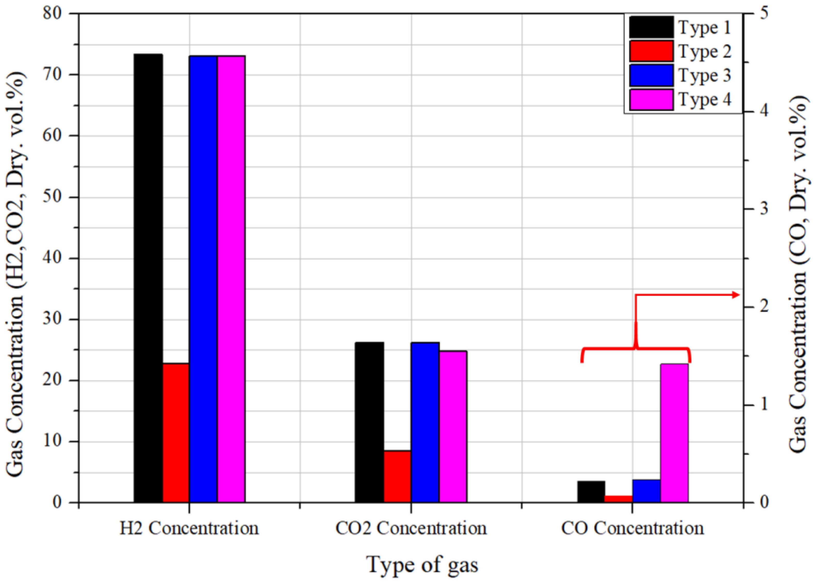
Additionally, Figure 7 indicates the methanol conversion in the four different setups at identical heat capacity. As observed, the most significant gap in the temperature difference at the hot-gas inlet for the four configurations is under 3.5%. Therefore, the reliability of the experimental result is ensured. The highest temperature at the evaporator outlet is for the type-4 evaporator at the packed-bed evaporator. Therefore, the methanol conversion is also the highest, at 97.3%. This is because the type-4 configuration is a combination of two evaporators. Additionally, the suitable operating temperature ranges from 250 to 300 °C, corresponding to the thermodynamic equilibrium composition. At the equilibrium state, it is expected that while the temperature ranges from 220 to 340 °C, the hydrogen concentration ranges from 60% to 72%, the CO concentration is under 1%, and the CO2 concentration is from 20% to 25%. The first one is shell-and-tube, which uses the wasted thermal energy from the hot-gas 1 outlet (TC3) of the packed-bed evaporator to recirculate the system before the evaporating process of the methanol/water mixture. The temperature of the hot-gas 2 inlet for the first shell-and-tube evaporator is 341 °C, and the temperatures of the hot-gas 2 outlet and cold-mixture outlet 2 are 115 °C and 93 °C, respectively. The thermocouple for the cold-mixture outlet is designated as TC2-reformer in the type-4 evaporator configuration. The second is the zirconia ball, and the type-4 shell-and-tube cold-mixture outlet is the cold-mixture inlet of the type-4 packed-bed evaporator. Altogether, this forms the closed-loop for the burner effluent. The thermocouple-TC7 is installed in the reformer right after the ceramic ball area to observe the temperature change of the mixture, called the cold-mixture 1 outlet. At 326 °C, the reforming reaction proceeds at a reasonable level. Conversely, because of the design of the evaporator, which together with the pipeline is long, the position in which it is installed in the system, and the inert catalyst which reduces the velocity of the fluid flow, the reformer is not supplied with sufficient thermal energy. Consequently, the type-2 evaporator has the lowest methanol conversion of 30%. Additionally, a slight difference in temperature and methanol conversion rate is observed for type-1 and type-3 evaporators. Moreover, Figure 8 shows the product concentration for the four different setups at identical heat capacity. A slight difference in the hydrogen and carbon dioxide concentrations for type-1, type-3, and type-4 is observed. However, because of the reasons mentioned above for type-2, the hydrogen and carbon dioxide concentrations are only one third compared with those for the other types; this is reflected in the methanol conversion. While the highest concentration of carbon monoxide is observed for type-4, nearly 1.42%, the lowest is observed for type-2. The carbon monoxide concentrations for type-1 and type-2 are nearly the same, and they are only one sixth of that observed for type-1. This is because the temperature at the reformer is nearly twice as high at the reformer for type-4 compared with the other types.
4. Conclusions
In this research, distinct designs for the evaporator of the 1 kW methanol-reforming system were developed, and the comparison and performance of individual configurations were evaluated at different input conditions.
- The flow-field mode was chosen for the system; the co-flow arrangement was more suitable for the methanol-reforming system than the counter-flow mode because of the insignificant difference in the evaporator outlet temperature.
- Comparison between the four types of evaporators proceeded at the same heat capacity; the type-4 evaporator demonstrated the most effective methanol conversion and temperature development performance. The methanol conversion reached over 97%, with the highest temperature of the evaporator outlet.
- Internal evaporation was feasible for the evaporating process; however, it should be combined with the external evaporation (shell-and-tube) to use the wasted thermal energy to improve the system’s performance.
- While the external evaporation method has received extensive attention from researchers, the system’s performance increases moderately. As a result, the performance of the system rises significantly when two methods of evaporation proceed simultaneously. This work will provide future researchers with many advantages for designing an integrated methanol-reforming system.
Author Contributions
Writing-original draft, N.V.T.; Formal analysis, N.V.T.; Investigation, N.V.T.; Visualization, N.V.T.; Data curation, Y.K.; Funding acquisition, S.Y. and H.K.; Project administration, S.Y. and H.K.; Validation, H.K.; Conceptualization, S.Y.; Supervision, S.Y.; Writing—review & editing, S.Y.; Methodology, S.Y.; Resources. S.Y. All authors have read and agreed to the published version of the manuscript.
Funding
This research was supported by the Korea Institute of Energy Technology Evaluation and Planning (KETEP) grant funded by the Korea government (MOTIE) (20214000000090, fostering human resources training in advanced hydrogen energy industry) and National Research Foundation of Korea (NRF) grant funded by the Korean government (no. NRF-2020M1A2A2080860).
Institutional Review Board Statement
Not applicable.
Informed Consent Statement
Not applicable.
Data Availability Statement
Not applicable.
Conflicts of Interest
The authors declare no conflict of interest.
Nomenclature
| S/C ratio | steam to carbon ratio |
| CH3OH | methanol |
| H2O | water |
| CO | carbon monoxide |
| CO2 | carbon monoxide dioxide |
| TC | thermocouple |
| GHSV | Gas hourly space velocity |
| ZnO | zinc oxide |
| CuO | copper (ii) oxide |
References
- Sarkar, J.; Bhattacharyya, S. Application of graphene and graphene-based materials in clean energy-related devices Minghui. Arch. Thermodyn. 2012, 33, 23–40. [Google Scholar] [CrossRef]
- Molino, A.; Larocca, V.; Chianese, S.; Musmarra, D. Biofuels production by biomass gasification: A review. Energies 2018, 11, 811. [Google Scholar] [CrossRef] [Green Version]
- Sikarwar, V.S.; Zhao, M.; Fennell, P.S.; Shah, N.; Anthony, E.J. Progress in biofuel production from gasification. Prog. Energy Combust. Sci. 2017, 61, 189–248. [Google Scholar] [CrossRef]
- Rathour, R.K.; Ahuja, V.; Bhatia, R.K.; Bhatt, A.K. Biobutanol: New era of biofuels. Int. J. Energy Res. 2018, 42, 4532–4545. [Google Scholar] [CrossRef]
- Palmer, G.; Floyd, J. Hydrogen as an energy carrier. In Energy Storage and Civilization; Springer: Cham, Switzerland, 2020; Volume 40. [Google Scholar]
- Moon, C.S. Estimations of the lethal and exposure doses for representative methanol symptoms in humans. Ann. Occup. Environ. Med. 2017, 29, 44. [Google Scholar] [CrossRef]
- Simon Araya, S.; Liso, V.; Cui, X.; Li, N.; Zhu, J.; Sahlin, S.L.; Jensen, S.H.; Nielsen, M.P.; Kær, S.K. A review of the methanol economy: The fuel cell route. Energies 2020, 13, 596. [Google Scholar] [CrossRef] [Green Version]
- Vlachos, D.G.; Caratzoulas, S. The roles of catalysis and reaction engineering in overcoming the energy and the environment crisis. Chem. Eng. Sci. 2010, 65, 18–29. [Google Scholar] [CrossRef]
- Schubert, A.W.K.; Brandner, J.; Fichtner, M.; Linder, G.; Schygulla, U. Microstucture devices for applications in thermal and chemical process engineering. Microscale Thermophys. Eng. 2001, 5, 17–39. [Google Scholar]
- Holladay, J.D.; Jones, E.O.; Dagle, R.A.; Xia, G.G.; Cao, C.; Wang, Y. High efficiency and low carbon monoxide micro-scale methanol processors. J. Power Sources 2004, 131, 69–72. [Google Scholar] [CrossRef]
- Pattekar, A.V.; Kothare, M.V. A microreactor for hydrogen production in micro fuel cell applications. J. Microelectromech. Syst. 2004, 13, 7–18. [Google Scholar] [CrossRef]
- Brooks, K.P.; Davis, J.M.; Fischer, C.M.; King, D.L.; Pederson, L.R.; Rawlings, G.C.; Stenkamp, V.S.; TeGrotenhuis, W.; Wegeng, R.S.; Whyatt, G.A. Fuel Reformation: Microchannel Reactor Design. In Microreactor Technology and Process Intensification: ACS Symposium Series; Wang, Y., Holladay, J.D., Eds.; Oxford University Press: New York, NY, USA, 2005; pp. 238–257. [Google Scholar]
- Kolb, G.; Hessel, V. Micro-structured reactors for gas phase reactions. Chem. Eng. J. 2004, 98, 1–38. [Google Scholar] [CrossRef]
- Wegeng, R.S.; Pederson, L.R.; TeGrotenhuis, W.E.; Whyatt, G.A.; Saffell, B.J. Compact fuel processors for fuel cell powered automobiles based on microchannel technology. Fuel Cells Bull. 2001, 3, 8–13. [Google Scholar] [CrossRef]
- Tezcan, I.; Avci, A.K. Parametric investigation of oxidative coupling of methane in a heat-exchange integrated microchannel reactor. J. Chem. Technol. Biotechnol. 2015, 90, 1827–1838. [Google Scholar] [CrossRef]
- Cuta, J.M.; Bennett, W.D.; McDonald, C.E.; Ravigururajan, T.S. Fabrication and testing of microchannel heat exchangers. In Proceedings of the Microlithography and Metrology in Micromachining, International Society for Optics and Photonics, Austin, TX, USA, 26 September 1995; Volume 2640. [Google Scholar] [CrossRef]
- Yoshida, K.; Tanaka, S.; Hiraki, H.; Esashi, M. A micro fuel reformer integrated with a combustor and a microchannel evaporator. J. Micromech. Microeng. 2006, 16, S191. [Google Scholar] [CrossRef]
- Kolios, G.; Frauhammer, J.; Eigenberger, G. Efficient reactor concepts for coupling of endothermic and exothermic reactions. Chem. Eng. Sci. 2002, 57, 1505–1510. [Google Scholar] [CrossRef]
- Palma, V.; Ruocco, C.; Castaldo, F.; Ricca, A.; Boettge, D. Ethanol steam reforming over bimetallic coated ceramic foams: Effect of reactor configuration and catalytic support. Int. J. Hydrog. Energy 2015, 40, 12650–12662. [Google Scholar] [CrossRef]
- Cui, X.; Kær, S.K. Two-dimensional thermal analysis of radial heat transfer of monoliths in small-scale steam methane reforming. Int. J. Hydrog. Energy 2018, 43, 11952–11968. [Google Scholar] [CrossRef]
- Yun, J.; Kim, Y.; Yu, S. Interactive heat transfer characteristics of 5 kW class shell-and-tube methane steam reformer with intermediate temperature heat source. Int. J. Hydrog. Energy 2020, 45, 21767–21778. [Google Scholar] [CrossRef]
- Yun, J.; Yu, S. Transient behavior of 5 kW class shell-and-tube methane steam reformer with intermediate temperature heat source. Int. J. Heat Mass Transf. 2019, 134, 600–609. [Google Scholar] [CrossRef]
- Shin, G.; Yun, J.; Yu, S. Thermal design of methane steam reformer with low-temperature non-reactive heat source for high efficiency engine-hybrid stationary fuel cell system. Int. J. Hydrog. Energy 2017, 42, 14697–14707. [Google Scholar] [CrossRef]
- Yun, J.; Cho, K.; Lee, Y.D.; Yu, S. Four different configurations of a 5 kW class shell-and-tube methane steam reformer with a low-temperature heat source. Int. J. Hydrog. Energy 2018, 43, 4546–4562. [Google Scholar] [CrossRef]
Figure 1.
Design of the reformer components.

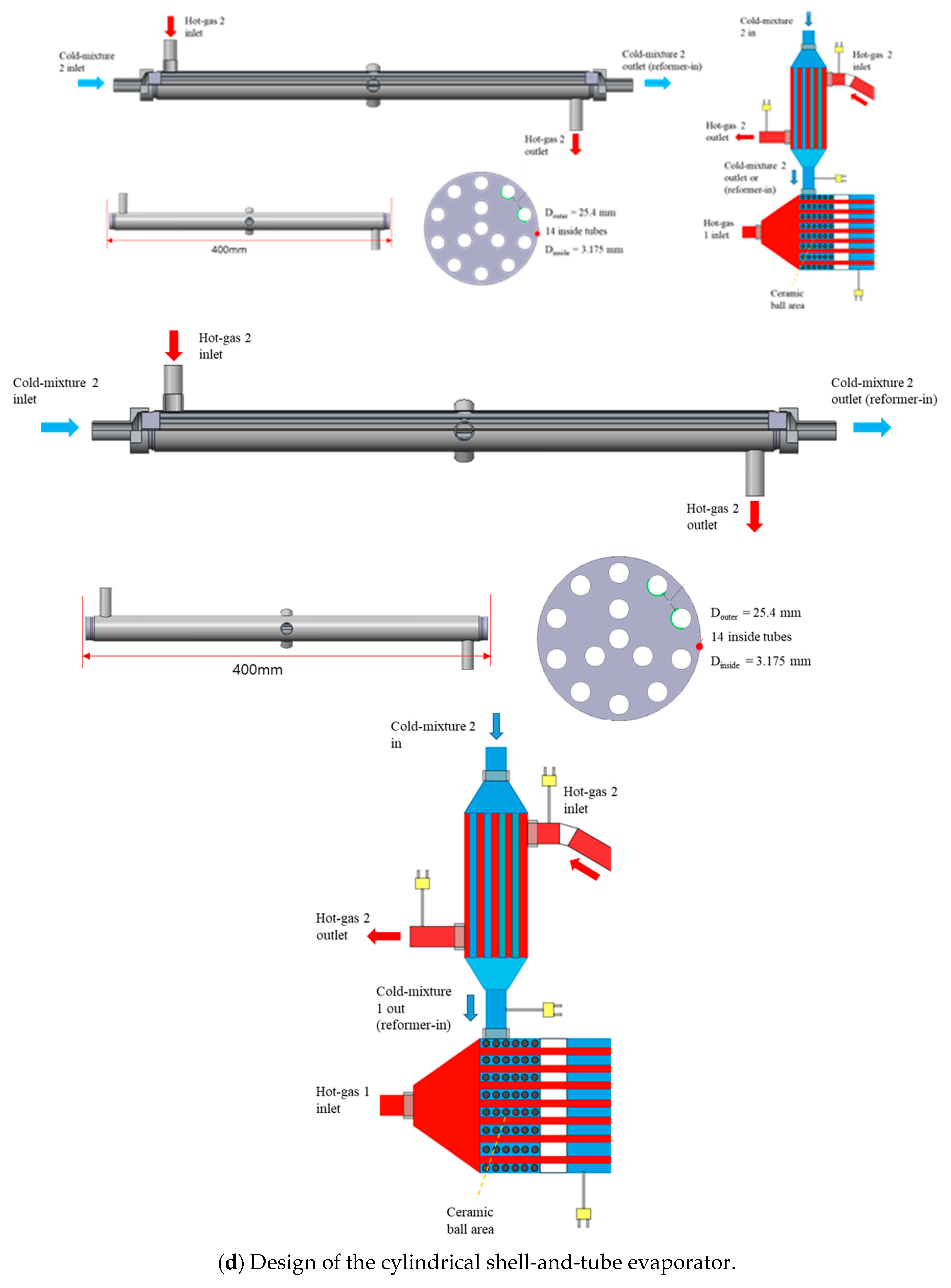
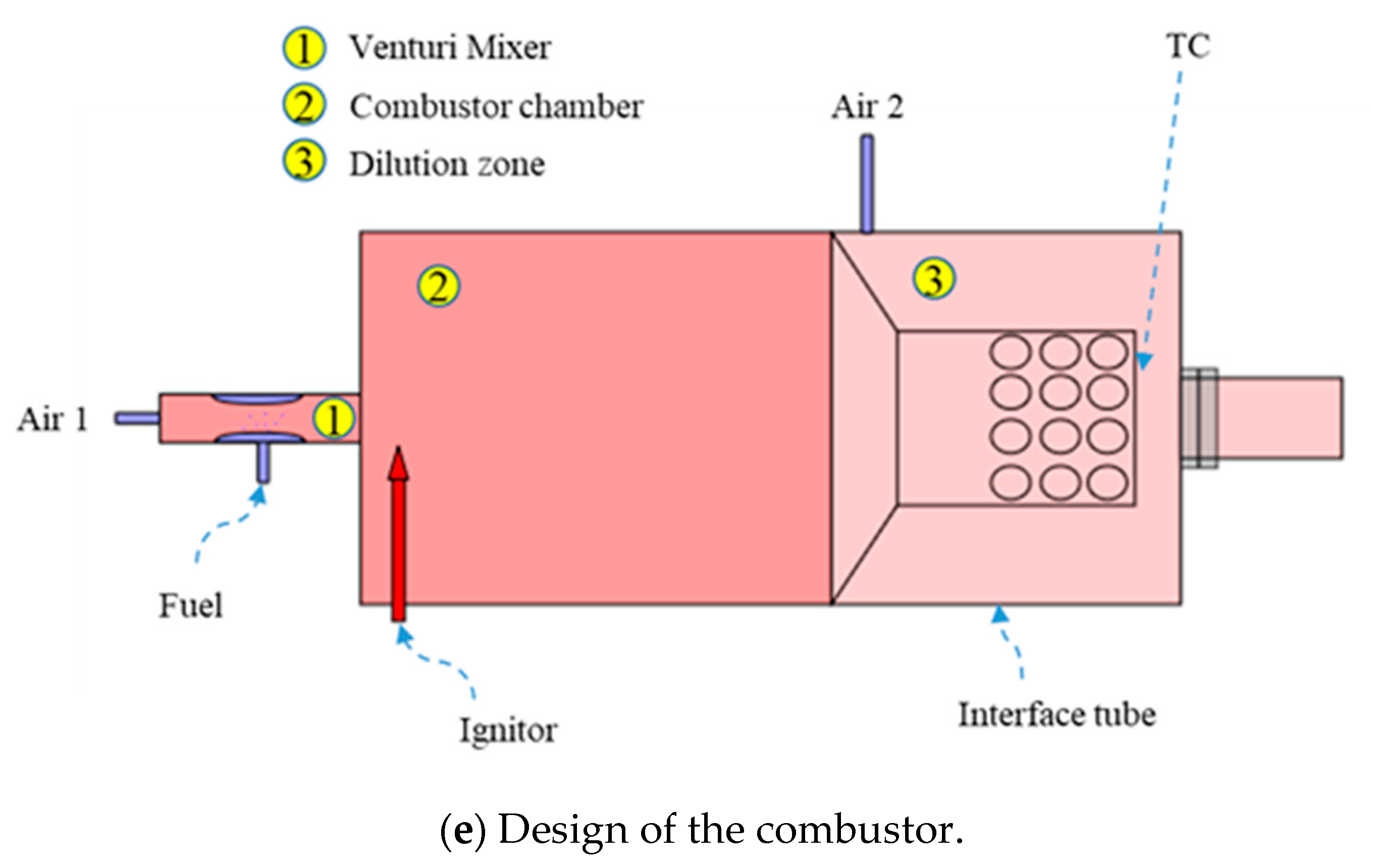
Figure 2.
Experimental configuration of the 1 kWe methanol-reforming system.
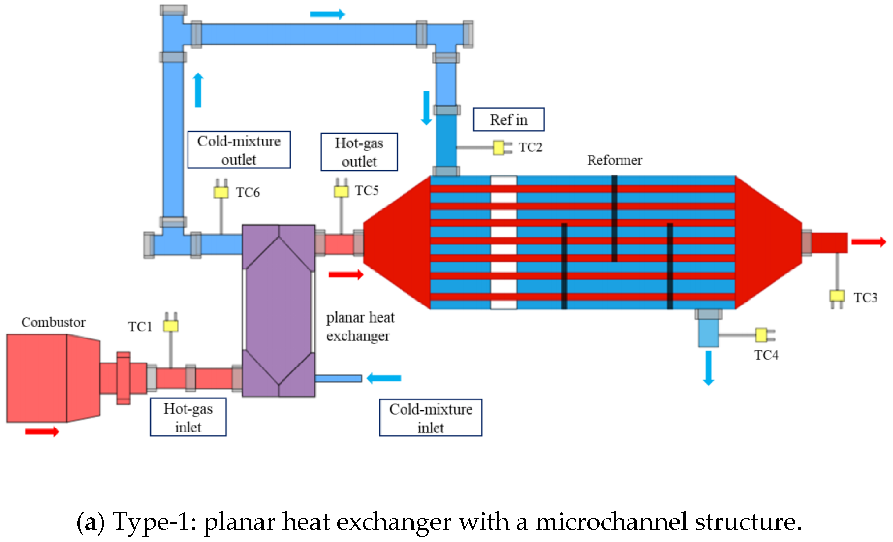
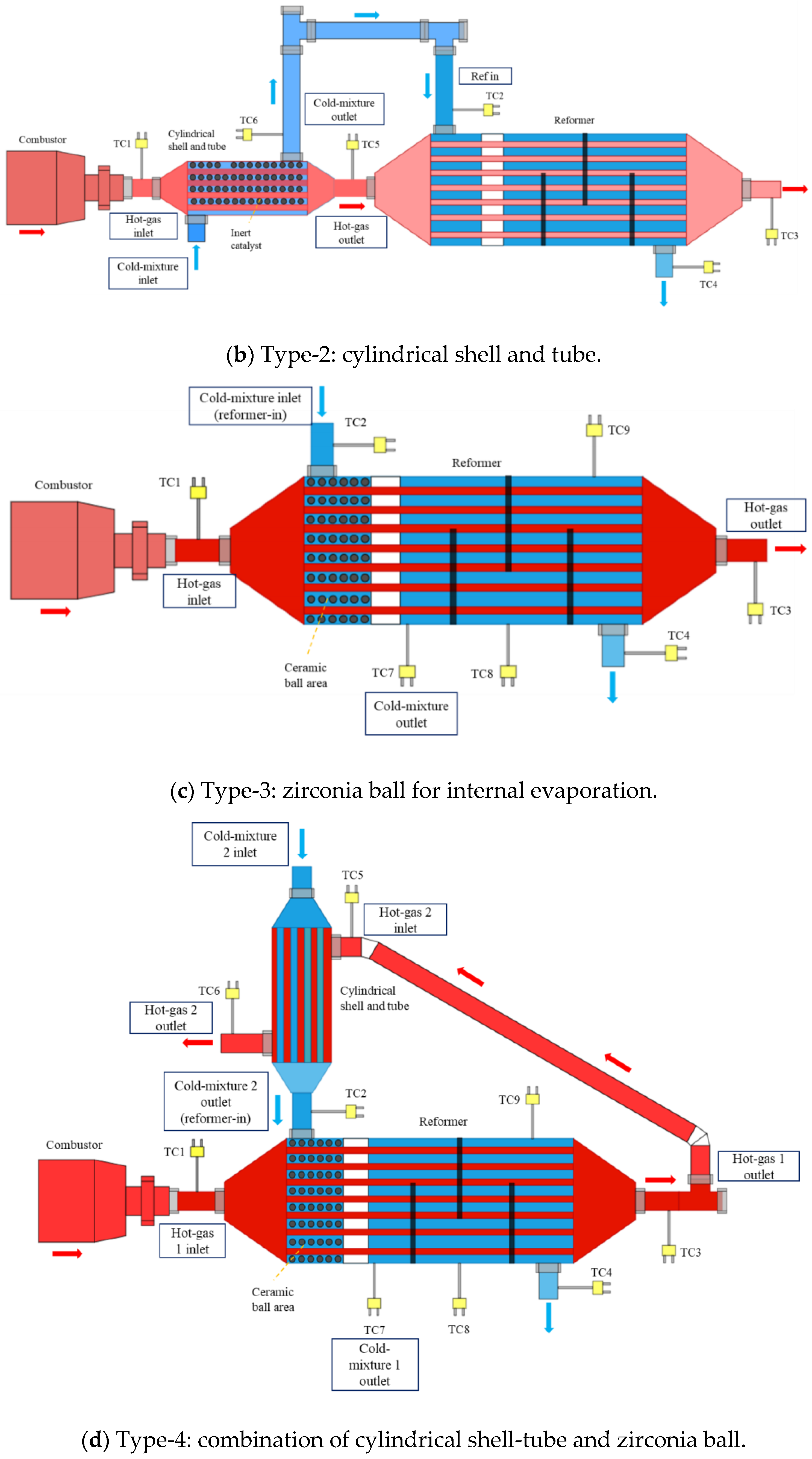
Figure 3.
Experimental setup for the methanol-reforming system with the type-4 evaporator, and a real experiment apparatus for the planar heat exchanger with microchannel structure.
Figure 3.
Experimental setup for the methanol-reforming system with the type-4 evaporator, and a real experiment apparatus for the planar heat exchanger with microchannel structure.


Figure 4.
Temperature changes at the measuring points under the stabilization process (type-4 evaporator, S/C ratio: 2.5, heat duty: 100%).
Figure 4.
Temperature changes at the measuring points under the stabilization process (type-4 evaporator, S/C ratio: 2.5, heat duty: 100%).

Figure 5.
Inlet and outlet temperatures of the evaporator in a flow arrangement (co-flow and counter-flow).
Figure 5.
Inlet and outlet temperatures of the evaporator in a flow arrangement (co-flow and counter-flow).
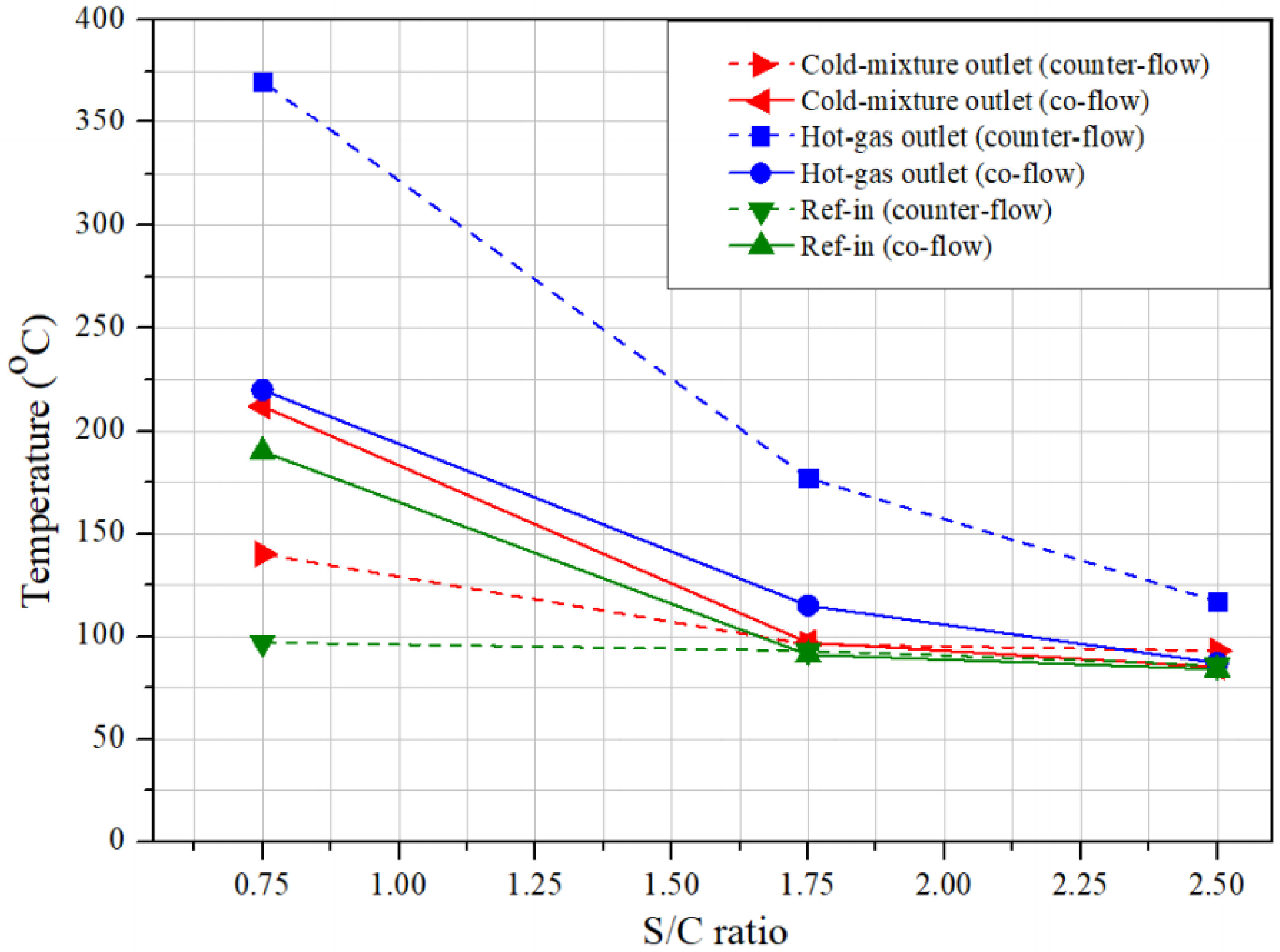
Figure 6.
Temperature measuring points at the evaporator inlet and outlet in four different setups at identical heat capacity (S/C ratio: 2.5, heat duty: 120%).
Figure 6.
Temperature measuring points at the evaporator inlet and outlet in four different setups at identical heat capacity (S/C ratio: 2.5, heat duty: 120%).

Figure 7.
Methanol conversion for the four different setups at identical heat capacity (S/C ratio: 2.5, heat duty: 120%).
Figure 7.
Methanol conversion for the four different setups at identical heat capacity (S/C ratio: 2.5, heat duty: 120%).
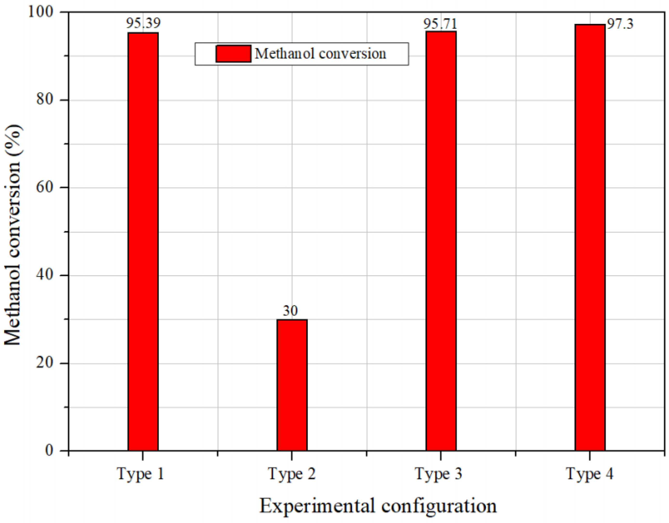
Figure 8.
Product concentration for the four different setups at identical heat capacity (S/C ratio: 2.5, heat duty: 120%).
Figure 8.
Product concentration for the four different setups at identical heat capacity (S/C ratio: 2.5, heat duty: 120%).

Table 1.
Experimental conditions of the methanol steam reformer system.
| Parameters | Values | Units |
|---|---|---|
| Reference conditions | ||
| Temperature of reactants for reforming | 25 | °C |
| Flow rate of methanol for reforming | 0.003 | mol/s |
| Flow rate of methanol for burner | 0.0015 | mol/s |
| S/C ratio | 2.5 | - |
| GHSV | 2400 | 1/h |
| Standard operating temperature | 300 | °C |
| Experiment parameters | ||
| S/C ratio | 0.75, 1.75, 2, 2.25, 2.5, 2.75, 3 | - |
| Flow rate of methanol for burner | 60, 70, 80, 90, 100 | % |
Publisher’s Note: MDPI stays neutral with regard to jurisdictional claims in published maps and institutional affiliations. |
© 2021 by the authors. Licensee MDPI, Basel, Switzerland. This article is an open access article distributed under the terms and conditions of the Creative Commons Attribution (CC BY) license (https://creativecommons.org/licenses/by/4.0/).
Share and Cite
MDPI and ACS Style
Trinh, N.V.; Kim, Y.; Kim, H.; Yu, S. Evaporation of Methanol Solution for a Methanol Steam Reforming System. Energies 2021, 14, 4862. https://doi.org/10.3390/en14164862
AMA Style
Trinh NV, Kim Y, Kim H, Yu S. Evaporation of Methanol Solution for a Methanol Steam Reforming System. Energies. 2021; 14(16):4862. https://doi.org/10.3390/en14164862
Chicago/Turabian StyleTrinh, Ngoc Van, Younghyeon Kim, Hongjip Kim, and Sangseok Yu. 2021. "Evaporation of Methanol Solution for a Methanol Steam Reforming System" Energies 14, no. 16: 4862. https://doi.org/10.3390/en14164862
Note that from the first issue of 2016, this journal uses article numbers instead of page numbers. See further details here.