Comparative Exergy Analysis of Units for the Porous Ammonium Nitrate Granulation
by
 , and
, and
Dmytro Levchenko
1,*, 
Andrii Manzharov
2,*,
Artem Artyukhov
3,
Nadiya Artyukhova
3 and
Jan Krmela
4,5
1
Innovative Ideas LLC, 36 Prokofieva St., 40016 Sumy, Ukraine
2
Technical Thermal Physics Department, Sumy State University, 2 Rymskogo-Korsakova St., 40007 Sumy, Ukraine
3
Department of Marketing, Sumy State University, 2 Rymskogo-Korsakova St., 40007 Sumy, Ukraine
4
Department of Numerical Methods and Computational Modeling, Faculty of Industrial Technologies in Púchov, 4 Alexander Dubček University of Trenčín, Študentská 2, 91150 Trenčín, Slovakia
5
Department of Transport Means and Diagnostics, Faculty of Transport Engineering, 5 University of Pardubice, Studentská 95, 53210 Pardubice, Czech Republic
*
Authors to whom correspondence should be addressed.
Energies 2021, 14(2), 280; https://doi.org/10.3390/en14020280
Submission received: 9 December 2020
/
Revised: 1 January 2021
/
Accepted: 4 January 2021
/
Published: 6 January 2021
(This article belongs to the Special Issue Exergy Analysis and Optimization of Energy Systems and Processes)
Abstract
:The article deals with the study on the efficiency of units for porous ammonium nitrate production. The ways which increase the effective implementation of energy resources are determined by including the ejector recycling module, heat and mass exchangers that utilize principles of regenerative indirect evaporative cooling, and the sub-atmospheric inverse Brayton cycle. Mixed exergy analysis evaluates all flows of the system contour as those of the same value. The target parameter for determining the efficiency of both systems is the ratio of the unit’s productivity to the exergy expenditures to produce the unit mass of the product. As a result, it is found that the mentioned devices and units enable to increase the efficiency of the basic scheme by 87%.
1. Introduction
Some chemical manufacturing units use energy to produce heat, electricity and raw materials which can amount to 85% of the production costs [1], making it possible to consider energy efficiency an essential component of the chemical unit design. The analysis in the research [2] enables to single out such initiative measures for increasing energy efficiency as improvement of existing processes; introduction (commercialization) of new processes; recycling; investments in renewable energy sources; creating products that save energy. However, the US chemical industry’s share of the total energy consumed is 6% despite all the implemented advanced energy efficiency measures [3].
Analysis of the data [4,5,6] concludes that various heat exchangers make almost half of the chemical units’ equipment. It is necessary to reduce the number of heat exchangers investigating new mechanisms for utilizing the temperature and humidity potential of flows to ensure energy efficiency in the units.
The estimated prime cost of chemical production shows that the cost of raw materials and their preparation, including its temperature potential change takes up to 70% of this indicator [7,8]. This fact requires further revision to preparing raw materials and semi-finished products and recycling production waste in both physical and energy forms.
Granulation process as a method of forming various substances from solutions and melts are widely used in the chemical industry [9,10,11] and the pharmaceutical [12,13,14,15] and other industries, as well as in the production of granules with unique properties [16] (for example, porous ammonium nitrate, considered in this work). The high-temperature heat transfer agents and wet streams in granulation processes open the prospect of introducing and successfully implementing effective methods to utilize the temperature and humidity potential of granulation units.
The porous ammonium nitrate can be produced in granulation units by various methods described in the works of Cardarelli and Janssen [17,18]. Analysis of the advantages and disadvantages of the existing methods for producing porous ammonium nitrate suggests a new approach. It is a combination of humidification and heat treatment of ordinary ammonium nitrate. Artyukhov and Artyukhova in their works [19,20] describe in detail various stages of this process. One should note that the production of the porous ammonium nitrate can be improved by creating additional conditions for the utilization of heat and moisture of the used heat transfer agent (drying agent) and using the obtained temperature and humidity potential at other stages of getting a granular product in the same unit.
There are two large blocks of methods for improving the energy efficiency of chemical units:
Block 1. To improve the devices of the chemical unit and the organization of the flow motion inside them (internal efficiency).
Block 2. To improve the flow motion organization and methods for changing their potential in a chemical unit (external efficiency).
One can give the following examples of methods from the first block: investigations on the active hydrodynamic modes in devices represented by Artyukhov [21], the design of multistage and multifunctional devices were considered by Artyukhov [22,23].
The key aspect in increasing the energy efficiency of the heat-mass transfer equipment provides the high specific indicators in the heat-mass transfer process (U value (factor), heat transfer coefficient, conductivity) and the required properties of heat-mass transfer surfaces. For example, the use of recuperators in which one or several heat carriers is transformed (condensed, evaporated, or boiled) can significantly increase the efficiency of the heat recovery process (according to the results of experimental studies GTI—Maisotsenko-Cycle Based Humidified Air Recuperator (HAR) and Water Heater Validation). For example, new thermodynamic principles for air-evaporative cooling of a large amount of heat carrier in cooling towers will provide a significant economic effect [24] (GTI—Method and apparatus for dew point evaporative product cooling). Besides, new materials and coating can be used to achieve these indicators and reach a new qualitative equipment level. Their implementation can significantly reduce energy consumption and increase equipment reliability, such as not using the pump working with highly efficient capillary-porous materials [25,26]. Efficient heat and mass transfer equipment allow developing new solutions for many industrial processes and units.
The simplest solution in the second block of energy efficiency methods is to use a heat transfer agent’s recirculation without additional preparation. The successful application of such a solution for multistage shelf dryers is presented in the study of Artyukhova [27]. However, there are more complex but more effective ways.
In the chemical industry, which simultaneously can use many flows with various substances with different thermal and caloric parameters, it is essential to ensure the most complete and positive effect of some processes on others. So, for example, in the utilization ejector module for the granulation scheme of porous ammonium nitrate [24,28], in addition to the nitrogen oxides conversion into higher oxides (the main effect), there is a significant inflow of thermal energy (secondary energy resource), which can and should be used (heating, drying, humidification, electricity generation [29,30]) for the needs of their chemical production or related enterprises/workshops or the population. It is advisable to organize a staged heat removal and recuperation since it will let more efficiently distribute energy between its consumers to ensure the available secondary energy resources use. In this regard, it is rational to use the evaporative indirect-regenerative cooling devices (M-cycle) since it allows removing heat effectively and obtaining highly enthalpy streams of highly humid air for their further humidification, heating or electricity generation. Besides, these devices use renewable energy from the environment [31] which, in addition to other renewable energy sources (e.g., solar), develops modules using the reverse sub-atmospheric Brayton cycle and makes a significant positive contribution to the overall scheme efficiency.
Some researchers and organizations (GTI, SoftInWay), who provide promising theoretical calculations results [30,32], have studied the sub-atmospheric reverse Brayton cycle. Among the leading scientific and practical problems in implementing this cycle is to develop a highly efficient heat and mass transfer device—a recuperator. The researchers propose to use a plate or spiral heat and mass transfer devices implementing the principles of evaporative indirect regenerative cooling (M-cycle). Therefore, it is relevant to study the potential of these devices in chemical production schemes to solve heat recovery and energy production problems.
Many methods can be used to efficiently analyze complex systems where various flows of heat, mass, and power are interdependent and interact pinch analysis, entropy generation minimization (EGM), exergy, thermoeconomic analysis and others. Pinch analysis (PA) shows its fast-developing nature for many fields of applications. PA offers a rational framework to identify energy saving targets and design efficient heat recovery networks, especially in the process industry [33,34]. However, according to authors [35] PA is not suitable for processes dealing with changes in pressures and compositions of the materials. In our further investigations, it seems rational to consider a combined innovative approach proposed by [35] and adopt it for optimization operating processes of units for the porous ammonium nitrate granulation. Such a powerful tool as EGM is useful for optimization operating processes in various applications (cryogenics, heat storage, power generation, etc.) through minimization of the calculated entropy generation rate. However, one should relate the thermodynamic non-ideality degree of the design to the physical features of the system, namely to finite dimensions, shapes, materials, finite speeds and finite-time intervals of operation, to take the maximum advantage from EGM method [36,37]. Thus, EGM will be more appropriate when the main operation modes and design of the elements, which are part of the complex system, will be defined. A similar situation is with thermoeconomic and exergo-economic analysis. It is complicated to obtain the necessary data for accurate calculation when the new layout of the unit for the porous ammonium nitrate granulation is considered, and new significant components are not designed or customized but considered black-box systems. Therefore, within the current investigation, we decided to provide an evaluative exergy analysis and amount only to the determination of system efficiency indicators [38].
Since the 50s of the last century, various industrial fields have implemented the exergy method of analysis that became one of the main ways to analyze, evaluate, and optimize the systems [39]. This approach is relatively flexible and universal for energy systems as a whole and their components [40,41,42,43,44,45,46]. The scheme components’ analysis allows evaluating their effectiveness separately and determining the element that leads to a decrease in the system efficiency. In publication [47], the authors describe the fundamentals and recommendations for applying the exergy analysis device.
This method is based on an approach in which all its flows come to a single “measure,” that is, “exergy”, dividing them into costs and beneficial effect (“fuel and product”) [47], and separating losses and exergy destruction [48]. If the initial data on the above flows are available at the design stage of the unit/device, it is possible to assess the exergy efficiency and, if necessary, to increase it.
Yukhimenko [49] demonstrates a technique for the exergy analysis of technological flows of the phosphorus-potassium fertilizer production, which uses the classical approach for the energy system. This technique defines product exergy due to its parameters. In this case, it is not entirely correct. The beneficial effect includes its quality, state and quantity at the output with minimal costs for its production, not the outcome thermodynamic parameters (affecting the exergy efficiency of the system) in the production of the material product.
A mixed exergy analysis is used to compare both schemes for porous ammonium nitrate production in the current work. This approach lets assess the efficiency of the schemes and the potential of secondary energy resources, which can be useful in this scheme or adjacent systems. The essence of the mixed exergy analysis is that the specific indicator, which is nothing more than the expenditure of specific exergy for production of a unit of mass of the product, is used for the assessment. It also allows determining the flows (energy, substandard, etc.) that can be utilized within the circuit design and minimize harmful emissions into the environment. For example, replacing an electric heater with an ejector recycling module to obtain the high temperatures required for the drying process leads to the fact that the residual heat is used to heat water and to generate electricity in the sub-atmospheric Brayton cycle [30,50,51]. In the research Živić [52], the authors calculated the Brayton cycle with different features. As a result, the exergy efficiency was assessed, which, in contrast to the thermal efficiency (which includes various types of energies), showed the preferable operating parameters in the cycle. Thus, the exergy analysis of complex systems and comparison of their versions, given its flexibility and versatility, is of scientific and practical interest.
2. Description of Schemes
This section describes the circuit design and technological scheme of granulation (Figure 1). The presented system produces porous ammonium nitrate as a component of an explosive industrial ANFO (ammonium nitrate—fuel oil). The principle of operation is as follows.
In the vortex granulator III, the seeding agents’ granules (ordinary ammonium nitrate) are fed for further humidification with an ammonium nitrate solution coming from mixer VIII and dehydration in the granulator with a stream of hot heat transfer agent (heated air) from the heat exchanger II. The saturated steam under pressure heats a hot heat transfer agent. Similarly, the ammonium nitrate solution is heated before it is applied to the seeding agent granule’s surface. After humidification and heat treatment (drying), the porous ammonium nitrate granules are sent for cooling in the device XIV. The exhaust air is sent to device XIII for cleaning. The scheme provides the reuse of production waste to prepare a solution of small granules, the dust of ammonium nitrate and ammonia water after it absorbed waste from the used heat transfer agent.
The unit is implemented for thermomechanical processing of the product from seeding agent’s granules with a solution applied on them to the productional granules with given physical parameters (density, humidity ratio content, porosity, hardness, geometric dimensions) with the maximum possible performance, and not to produce work, cold or heat. Thus, all incoming exergy streams are consumed to obtain a mass flow of the final product (granular ammonium nitrate). In this case, the exergy potential of the final product is not significant, and the mass flow rate mainly influences the efficiency of the scheme.
3. Methodology
This section provides an approach to the unit’s exergy analysis to produce the porous ammonium nitrate and the contour elements included in the system, restricting it with a conditional control contour “M” (Figure 2), crossed by supplied and removed exergy flows (mechanical/electrical, substance flow, chemical) of various amount, quality, and type. Exergy losses are also diverted through the control contour.
When performing an exergy analysis of any system, it is necessary correctly to determine the input and output exergy flows and their role. The general exergy balance Equation (2):
The exergy equation of a one-component substance flow is as follows:
Since humid air is one of the working substances in the system, we will observe it as a two-component substance (air and water vapor) for convenient calculation. Then, the equation of a two-component substance will be as follows:
In the previous calculation model, humid air is considered a real mixture by Equation (3). The exergy equation can be rewritten for an ideal mixture as (4). The calculations of humidity ratio of water vapor in humid air are a prerequisite, omitting which one can get a false result:
We will use Equation (2) by introducing some transformations to calculate the exergy of a solid:
One can use the approximate equation [39] to calculate the exergy of the fuel supplied to the system:
where —coefficient for gaseous fuels with more than one carbon atom in their molecules. This equation is used with coefficient for liquid fuel.
It is permissible to use the approximate Equation (6) from the point of view of obtaining a quantitatively correct result since under the conditions, usual exergy losses during combustion are so significant that the error related to the approximate methods turns out to be quite acceptable.
4. Assessing the Systems Effectiveness
This section deals with assessing the effectiveness of both systems using the exergy analysis of mixed exergy indicators. This analysis allows us to amount all the production costs to a single dimension—“exergy”. The exergy efficiency is one of the target functions for exergy analysis of energy systems designed to produce heat, cold or work (7). The target function for technological systems designed to create a material product is the ratio of the material product performance to the exergy expenditure for its production (8). The task is to minimize the value of or to obtain an additional useful effect/product:
Environmental parameters, which form the starting point for the substance flow exergy are pressure , temperature .
4.1. Basic Scheme
The first stage of the analysis is to derive an equation of all flows brought to the system—costs, Equation (8):
Since the basic scheme does not provide for NOx recycling and does not generate electricity, thus Equation (8) for the basic scheme is:
Table 1 summarizes the exergy values included in Equation (10), Figure 3 shows the incoming exergy stream and outgoing one via Sankey diagram:
The following Equation (8) finds the specific exergy expenditure to produce a product in the base system:
4.2. Modified Scheme
The first stage of the analysis is to derive an equation of all flows brought to the system—costs, Equation (11). Due to the inclusion of Brayton’s sub-atmospheric inverse cycle with Maisotsenko’s humid air recuperator (HAR) in the production scheme, some electricity costs are compensated:
Preliminary calculation of the parameters at the definite points of the modified scheme, thermal loads and electrical powers supplied or taken away in the elements of the scheme.
Thermal load on the device XI:
Heat flux on the device V:
Water mass flow rate through device V:
The equation for the combustion reaction of natural gas with oxygen:
33.6 kg of oxygen is required to burn 8.4 kg of natural gas. Heat flux on the device II:
The flow temperature “c” after device V:
Thermal load on the device XIII:
The flow temperature “c” after device XIII:
Thermal load on the device IV:
Humid air flow rate in the outlet of the device IV:
Air flow rate in the inlet of the device IV:
Fans with electric motor power were selected for the obtained features of devices II and IV:
A preliminary calculation of the Brayton’s sub-atmospheric inverse cycle with HAR [30] is carried out to determine the generated useful power. Its scheme and the cycle in h-s coordinates is shown in Figure 4 and Figure 5, respectively.
Specific heat flow in the solar collector:
Specific heat flow on M device:
Mass flow rate of air supplied to the cycle:
Mass air flow resulting from the mixing process:
Air parameters at the outlet of the turbine (T) are defined in the following way: adiabatic extension temperature is found . Then, considering the adiabatic efficiency of the turbine , temperature is calculated :
Specific work of the turbine:
The parameters of the air at the outlet of the HMX are determined as follows: according to the recommended humidity ratio at the outlet of the product channels [30] the saturated humid air temperature is calculated.
The parameters of the air at the outlet of the compressor are determined as follows: air is compressed from to with the temperature reached by removing heat during the compression by the cooling agent.
Compressor power:
Net electrical power output produced in a cycle is:
Table 2 comprises exergy values, included in (11). Figure 6 demonstrates the supplied exergy flows and production supplied flow via Sankey diagram.
The specific exergy expenditure to produce a product in a modified system is found by the equation:
5. Discussion
The obtained results assume that it is reasonable to consider in more detail the elements in the modified scheme, their mutual influence, and dependence on the operating mode of the granulator. It is rational to analyze the exergy efficiency of the basic and modified schemes in dynamics, namely, at different operating modes of the granulator and/or other types of granulators. It is due to the fact that changes in the granulator’s operating modes (its performance) entail a chain of significant changes in the operating modes of the related components in the scheme: if the granulator performance is changed (for example, reduced) → there is lower consumption of the recovered stream “d” → lower consumed amount of natural gas for recycling of lower oxides in the ejector module “I” → lower heat flow removed in heat and mass transfer (II, IV) device and recuperators (V, XI, XIII).
A problem with the calculation of heat and mass exchangers and the heat recovery reactor causes difficulty in identifying the composition of the flow “c” after the ejector module. Thus, with a significant decrease in the temperature of the flow “c” caused by stepwise heat removal, it is difficult to determine the nature of the heat and mass transfer processes occurring in device IV since condensation and chemical interaction between the components of the flow “c” are possible. Hence, the following problem arises with determining the composition, state parameters and the ongoing physical and chemical processes in the waste heat reactor (XII).
As a result of the exergy analysis of the basic and modified granulation schemes for porous ammonium nitrate, the following indicators of their specific efficiency are obtained:
Thus, the use of an ejector recycling module (as a way to recycle substandard ammonium nitrate and nitrogen oxide of the formula NxO), a sub-atmospheric cycle inverse (as a way to recycle excess heat and generate energy) and two heat and mass exchangers according to the Maisotsenko cycle (as a way to humidify ammonium nitrate in a highly humid air flow and organizing a more efficient heat recovery process) increase the efficiency of the basic scheme by:
A porous ammonium nitrate granulation workshop often is located within a nitrogen fertilizer plant. Therefore, it is worth noting that the basic scheme should be modified in terms of the amount and cost of resources available at the enterprise and the present mass and energy flows from adjacent industries/workshops. The task of further research is theoretical modeling and experimental operation of the HMX (IV) and the waste heat reactor (XII), concerning the effect of the incoming flows on operation modes of these devices.
6. Conclusions
Within this work, the authors proposed a modified scheme of the installation for porous ammonium nitrate granulation. They showed the potential for the energy efficiency of the new system compared to the basic one (used in practice) through the exergy analysis. The study of heat and mass exchange processes, chemical transformations, and changes in the phase composition of flows in these devices is of particular interest. One of the directions for further research is to improve the method for obtaining porous ammonium nitrate, particularly the organization of the optimal technological and constructive solution for the humidification and drying stages.
The main innovative solutions in the modified scheme are vortex granulator with the new organization of flows’ interactive, an ejector module for the utilization of substandard flow; the use of heat and mass exchangers of indirect regenerative evaporative cooling as recuperative, cooling and humidifying equipment; a power generation and heat recovery module based on a sub-atmospheric inverse Brayton cycle. The calculations showed a significant energy efficiency of the proposed solutions.
Further directions of study are:
- -
- optimization of flow arrangement in the vortex granulator as a core device in the scheme to provide additional utilization of fine fraction of ammonium nitrate;
- -
- consideration of various combinations of operating modes in the same workspace of the device to meet the drying agent’s optimal heat potential;
- -
- detailed calculations of the proposed scheme and its further study are required, considering the design features, materials and processes inside the equipment;
- -
- experimental investigation of devices for indirect regenerative evaporative cooling;
- -
- detailed analysis of the proposed sub-atmospheric inverse Brayton cycle and other cycles as a core for power generation and heat recovery module.
After the detailed study of the mentioned components in the new scheme, it seems rational to conduct its optimization concerning economic indicators.
Author Contributions
Conceptualization of the study of various technological schemes of porous ammonia nitrate production lines were performed jointly by D.L., A.A. and A.M., A.A. provided theoretical basics of porous ammonium nitrate obtaining. J.K. and N.A. were involved in literature review process. D.L. and A.M. developed methodology relevant software and performed obtained data validation and analysis. A.M. drew figures and edited the manuscript. D.L. and A.A. carried out general supervision. A.M. and J.K. administrated the project. All authors have read and agreed to the published version of the manuscript.
Funding
This research work had been supported by the Ministry of Science and Education of Ukraine under the project “Technological bases of multistage convective drying in small-sized devices with utilization and heat recovery units”, project No. 0120U100476 and the Cultural and Educational Grant Agency of the Slovak Republic (KEGA), project No. KEGA 002TnUAD-4/2019, project “Advancement and support of R&D for “Centre for diagnostics and quality testing of materials” in the domains of the RIS3 SK specialization“, code NFP313011W442.
Institutional Review Board Statement
Not applicable.
Informed Consent Statement
Not applicable.
Data Availability Statement
Data is contained within the article.
Acknowledgments
The authors acknowledge the support by the Innovative Ideas LLC and CEO Stanislav Shevchenko.
Conflicts of Interest
The authors declare no conflict of interest. The funders had no role in the design of the study; in the collection, analyses, or interpretation of data; in the writing of the manuscript, or in the decision to publish the results.
Nomenclature
| specific isobaric heat capacity | |
| humidity ratio in humid air | |
| system efficiency indicator | |
| specific exergy flow of the substance | |
| enthalpy | |
| specific work | |
| mass flow rate | |
| pressure | |
| specific heat flow | |
| entropy | |
| temperature | |
| substance exergy flow | |
| power | |
| heat flow | |
| gas constant | |
| absolute temperature | |
| Greek symbols | |
| efficiency coefficient | |
| Subscripts | |
| dead state | |
| process air | |
| air to spray solution | |
| air for product cooling | |
| ambient air | |
| ambient air | |
| ambient air supplied to Brayton’s sub-atmospheric inverse cycle with HAR | |
| a substandard stream that passed the recycling module in which lower oxides passed into higher ones; it is also a thermal energy source necessary for the unit’s operation | |
| irregular flow | |
| dry air | |
| destruction | |
| exergy | |
| fuel | |
| humid air | |
| input | |
| isentropic | |
| index | |
| loss | |
| ammonium nitrate | |
| seeding agent of the ammonium nitrate | |
| output | |
| product | |
| useful effect | |
| saturation state | |
| water vapor | |
| water | |
| Superscripts | |
| basic | |
| modified | |
| Designations on the diagrams | |
 | exergy of the substance flow |
 | material flow |
 | exergy of energy flow |
References
- Carole, T.; Scheihing, P.; Sousa, L. Energy Efficiency and Use in the Chemical Industry. ACEEE Proc. 2001, 1, 267–275. [Google Scholar]
- Fawkes, S.; Oung, K.; Thorpe, D. Best Practices and Case Studies for Industrial Energy Efficiency Improvement. In An Introduction for Policy Makers; UNEP DTU Partnership: Copenhagen, Denmark, 2016; p. 173. [Google Scholar]
- Patt, J.J.; Banholzer, W.F. Improving Energy Efficiency in the Chemical Industry. Bridg. Energy Effic. 2009, 39, 15–21. [Google Scholar]
- Duroudier, J.-P. Heat Transfer in the Chemical, Food and Pharmaceutical Industries; Elsevier: Amsterdam, The Netherlands, 2017; ISBN 978-1-78548-188-8. [Google Scholar]
- Hipple, J. Chemical Engineering for Non-Chemical Engineers; Elsevier: Amsterdam, The Netherlands, 2017; ISBN 978-1-119-30965-9. [Google Scholar]
- Kapustenko, P.O.; Kukulka, D.J.; Arsenyeva, O.P. Intensification of heat transfer processes. Chem. Eng. Trans. 2015, 45, 1729–1734. [Google Scholar] [CrossRef]
- Beller, M.; Böhland, T.; Demtröder, D.; Ebenhoech, J.; Ernst, S.; Ewers, J.; Haber, S.; Hoer, R.; Hirth, T.; Jahn, D.; et al. Change in the Raw Materials Base; GDCh: Frankfurt, Germany, 2010. [Google Scholar]
- Ali, M.F.; Ali, B.M.; Speight, J.G. Handbook of Industrial Chemistry: Organic Chemicals; McGraw-Hill Education: New York, NY, USA, 2005; ISBN 9780071410373. [Google Scholar]
- Stahl, H.; Van Vaerenbergh, G. Single-Pot Processing. In Handbook of Pharmaceutical Granulation Technology, 2nd ed.; CRC Press: Boca Raton, FL, USA, 2005; pp. 311–332. ISBN 9780849354953. [Google Scholar]
- Litster, J.; Ennis, B. The Science and Engineering of Granulation Processes; 31 March 2004; Springer: Berlin/Heidelberg, Germany, 2004; ISBN 978-94-017-0546-2. [Google Scholar]
- Stahl, H. Comparing Granulation Methods; GEA Pharma Systems: Hürth, Germany, 2010. [Google Scholar]
- Muralidhar, P.; Bhargav, E.; Sowmya, C. Novel Techniques of Granulation: A Review. Int. Res. J. Pharm. 2016, 7, 8–13. [Google Scholar] [CrossRef]
- Stahl, H. Comparing Different Granulation Techniques. In Pharmaceutical Technology; PharmTech: Muellheim, Germany, 2004; pp. 22–33. [Google Scholar]
- Sahoo, C.K.; Rao, S.R.M.; Sudhakar, M.; Bhaskar, J. Advances in granulation technology. Res. J. Pharm. Technol. 2016, 9, 571–580. [Google Scholar] [CrossRef]
- Athar, M. A technical note on granulation technology: A way to optimise granules. Int. J. Pharm. Sci. Rev. Res. 2013, 4, 55–67. [Google Scholar]
- Artyukhov, A.Y.; Sklabinskiy, V.I. Experimental and industrial implementation of porous ammonium nitrate producing process in vortex granulators. Nauk. Visnyk Natsionalnoho Hirnychoho Universytetu 2013, 6, 42–48. [Google Scholar]
- Cardarelli, F. Fuels, Propellants, and Explosives. In Materials Handbook; Springer International Publishing: Cham, Switzerland, 2018; pp. 1465–1496. ISBN 3527302107. [Google Scholar]
- Janssen, T.J. Explosive Materials: Classification, Composition and Properties; Nova Science Publishers: New York, NY, USA, 2011; ISBN 1617611883. [Google Scholar]
- Artyukhov, A.E.; Sklabinskiy, V.I. Investigation of the Temperature Field of Coolant in the Installations for Obtaining 3D Nanostructured Porous Surface Layer on the Granules of Ammonium Nitrate. J. Nano-Electron. Phys. 2017, 9, 01015. [Google Scholar] [CrossRef]
- Artyukhova, N.O. Morphological Features of the Nanoporous Structure in the Ammonium Nitrate Granules at the Final Drying Stage in Multistage Devices. J. Nano-Electron. Phys. 2020, 12, 04036. [Google Scholar] [CrossRef]
- Artyukhov, A.; Obodiak, V.; Boiko, P.; Rossi, P. Computer modeling of hydrodynamic and heat-mass transfer processes in the vortex type granulation devices. In CEUR Workshop Proceedings; ICTERI: Kyiv, Ukraine, 2017; pp. 33–47. [Google Scholar]
- Artyukhov, A.E.; Artyukhova, N.O. Technology and the Main Technological Equipment of the Process to Obtain N4HNO3 with Nanoporous Structure. In Springer Proceedings in Physics; Springer: Berlin/Heidelberg, Germany, 2019; pp. 585–594. [Google Scholar]
- Artyukhov, A.E.; Ivaniia, A.V. Obtaining porous ammonium nitrate in multistage and multifunctional vortex granulators. Nauk. Visnyk Natsionalnoho Hirnychoho Universytetu 2017, 7, 68–75. [Google Scholar]
- Levchenko, D.; Yurko, I.; Artyukhov, A.; Baga, V. Maisotsenko cycle applications for multistage compressors cooling. IOP Conf. Ser. Mater. Sci. Eng. 2017, 233, 012023. [Google Scholar] [CrossRef] [Green Version]
- Levchenko, D.; Pavlenko, I.; Shulumei, A.; Ochowiak, M.; Manzharov, A. Parameter Identification of the Capillary Rising Process in Nanomaterials for Evaporative Cooling Applications. In Design, Simulation, Manufacturing: The Innovation Exchange; Springer: Cham, Switzerland, 2020; pp. 201–215. [Google Scholar]
- Choi, C.-H.; Krishnan, S.; TeGrotenhuis, W.; Chang, C.-H. Capillary Rise of Nanostructured Microwicks. Micromachines 2018, 9, 153. [Google Scholar] [CrossRef] [PubMed] [Green Version]
- Artyukhova, N.O.; Krmela, J. Nanoporous Structure of the Ammonium Nitrate Granules at the Final Drying: The Effect of the Dryer Operation Mode. J. Nano-Electron. Phys. 2019, 11, 04006. [Google Scholar] [CrossRef]
- Levchenko, D.O.; Artyukhov, A.E.; Yurko, I.V. Maisotsenko cycle applications in multi-stage ejector recycling module for chemical production. IOP Conf. Ser. Mater. Sci. Eng. 2017, 233, 012024. [Google Scholar] [CrossRef] [Green Version]
- Buyadgie, D.; Buyadgie, O.; Drakhnia, O.; Brodetsky, P.; Maisotsenko, V. Solar low-pressure turbo-ejector Maisotsenko cycle-based power system for electricity, heating, cooling and distillation. Int. J. Low-Carbon Technol. 2015, 10, 157–164. [Google Scholar] [CrossRef] [Green Version]
- Khalatov, A.A.; Severin, S.D.; Brodetsky, P.I.; Maisotsenko, V.S. Brayton’s subatmospheric inverse cycle with regeneration of output heat by Maisotsenko’s cicle. Rep. Natl. Acad. Sci. Ukr. 2015, 72–79. [Google Scholar] [CrossRef]
- Mahmood, M.H.; Sultan, M.; Miyazaki, T.; Koyama, S.; Maisotsenko, V.S. Overview of the Maisotsenko cycle—A way towards dew point evaporative cooling. Renew. Sustain. Energy Rev. 2016, 66, 537–555. [Google Scholar] [CrossRef]
- Kozlov, A.; Chudnovsky, Y. Combined Cooling, Heating And Power System. U.S. patent 16/297928, 12 September 2019. [Google Scholar]
- Piacentino, A. Thermal analysis and new insights to support decision making in retrofit and relaxation of heat exchanger networks. Appl. Therm. Eng. 2011, 31, 3479–3499. [Google Scholar] [CrossRef] [Green Version]
- Asante, N.D.K.; Zhu, X.X. An Automated and Interactive Approach for Heat Exchanger Network Retrofit. Chem. Eng. Res. Des. 1997, 75, 349–360. [Google Scholar] [CrossRef]
- Safder, U.; Ifaei, P.; Yoo, C. A novel approach for optimal energy recovery using pressure retarded osmosis technology: Chemical exergy pinch analysis—Case study in a sugar mill plant. Energy Convers. Manag. 2020, 213, 112810. [Google Scholar] [CrossRef]
- Bejan, A. Method of entropy generation minimization, or modeling and optimization based on combined heat transfer and thermodynamics. Rev. Générale Therm. 1996, 35, 637–646. [Google Scholar] [CrossRef]
- Korpyś, M.; Gancarczyk, A.; Iwaniszyn, M.; Sindera, K.; Jodłowski, P.J.; Kołodziej, A. Analysis of entropy production in structured chemical reactors: Optimization for catalytic combustion of air pollutants. Entropy 2020, 22, 1017. [Google Scholar] [CrossRef] [PubMed]
- Besagni, G. Ejectors on the cutting edge: The past, the present and the perspective. Energy 2019, 170, 998–1003. [Google Scholar] [CrossRef]
- Брoдянский, B.; Фратшер, B.; Михалек, K. Эксергетический метoд и егo прилoжения; Энергoатoм: Мoсква, Рoссия, 1988; ISBN 5-283-00152-0. [Google Scholar]
- Morosuk, T.; Tsatsaronis, G. Advanced exergy-based methods used to understand and improve energy-conversion systems. Energy 2019, 169, 238–246. [Google Scholar] [CrossRef]
- Sayadi, S.; Tsatsaronis, G.; Morosuk, T.; Baranski, M.; Sangi, R.; Müller, D. Exergy-based control strategies for the efficient operation of building energy systems. J. Clean. Prod. 2019, 241, 118277. [Google Scholar] [CrossRef]
- Athari, H.; Soltani, S.; Rosen, M.A.; Gavifekr, M.K.; Morosuk, T. Exergoeconomic study of gas turbine steam injection and combined power cycles using fog inlet cooling and biomass fuel. Renew. Energy 2016, 96, 715–726. [Google Scholar] [CrossRef]
- Fazelpour, F.; Morosuk, T. Exergoeconomic analysis of carbon dioxide transcritical refrigeration machines. Int. J. Refrig. 2014, 38, 128–139. [Google Scholar] [CrossRef]
- Jannatkhah, J.; Najafi, B.; Ghaebi, H. Energy and exergy analysis of combined ORC—ERC system for biodiesel-fed diesel engine waste heat recovery. Energy Convers. Manag. 2020, 209, 112658. [Google Scholar] [CrossRef]
- MOROSUK, T.; TSATSARONIS, G. A new approach to the exergy analysis of absorption refrigeration machines. Energy 2008, 33, 890–907. [Google Scholar] [CrossRef]
- Morosuk, T.; Tsatsaronis, G. Advanced exergy analysis for chemically reacting systems—Application to a simple open gas-turbine system. Int. J. Thermodyn. 2009, 12, 105–111. [Google Scholar] [CrossRef]
- Morosuk, T.; Tsatsaronis, G. Splitting physical exergy: Theory and application. Energy 2019, 167, 698–707. [Google Scholar] [CrossRef]
- Shargut, Y. Exergy; Shargut, R.P., Ed.; Energiia: Moscow, Russia, 1968. [Google Scholar]
- Yukhimenko, N.; Vakal, S. The exergy analysis of energy efficiency of the technology of granulated phosphorus-potassium fertilizers. East.-Eur. J. Enterp. Technol. 2016, 5, 4–10. [Google Scholar] [CrossRef]
- Quoilin, S.; Lemort, V. Technological and Economical Survey of Organic Rankine Cycle Systems. In Proceedings of the 5th European Conference Economics and Management of Energy in Industry, Algarve, Portugal, 14–17 April 2009; Volume 278, p. 12. [Google Scholar]
- Madhawa, H.; Golubovic, M.; Worek, W.; Ikegami, Y. Optimum design criteria for an Organic Rankine cycle using low-temperature geothermal heat sources. Energy 2007, 32, 1698–1706. [Google Scholar] [CrossRef]
- Živić, M.; Galović, A.; Avsec, J.; Holik, M. Exergy analysis of a Brayton cycle with variable physical properties and variable composition of working substance. Teh. Vjesn. Tech. Gaz. 2016, 23, 801–808. [Google Scholar] [CrossRef] [Green Version]
Figure 1.
Considered exergy contour B of the basic technological scheme of porous ammonium nitrate granulation. I—gas blower; II—air heater; III—granulator; IV—bunker; V—compressor; VI—pump; VII—filter; VIII—capacity; IX—bunker; X—pump; XI—tank 2; XII—gas blower; XIII—absorber XIV—cooler; XV—gas blowers.
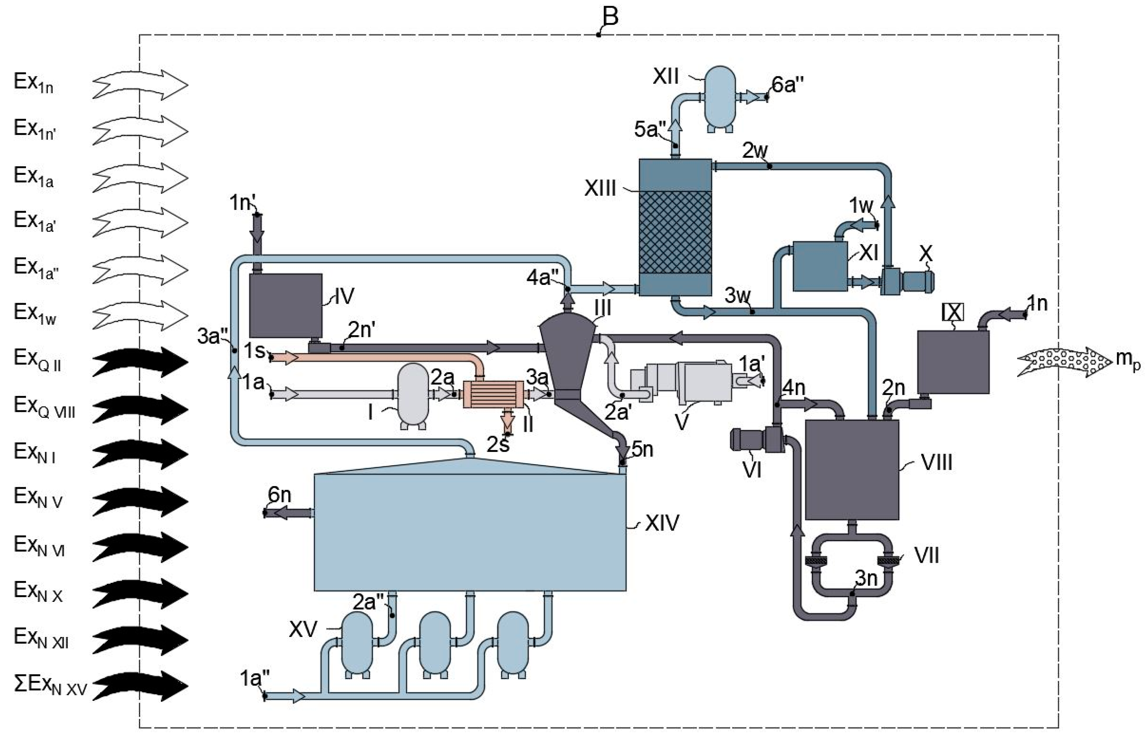
Figure 2.
Considered exergy contour M of the modified technological scheme of porous ammonium nitrate granulation. I—ejector; II—HMX 1; III—granulator; IV—HMX 2; V—heat exchanger 1; VI—pump; VII—filter; VIII—tank; IX—bunker; X—Brayton’s sub-atmospheric inverse cycle with HAR; XI—heat exchanger 2; XII—Reactor-Utilizer; XIII—heat exchanger 3; XIV—cooler; XV—gas blowers; XVI, XVII—fan; XVII—gas blower (compressor).
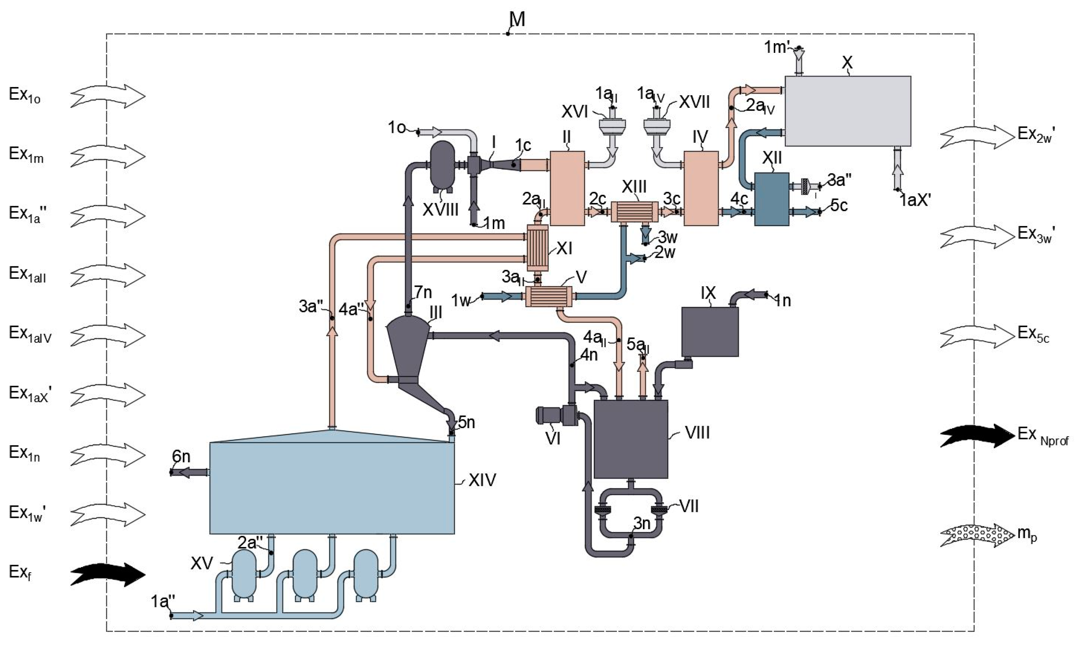
Figure 3.
Sankey diagram for basic scheme.

Figure 4.
Brayton’s sub-atmospheric inverse cycle with HAR. SC—solar collector; HAR—humidified air recuperator; T—turbine; C—compressor; 1–8—points for determining state parameters of the flow within the processes in the cycle: 1–2—heating in SC; 2–2*—cooling in dry channels of the HAR; 2*–3—humidifying in wet channels of the HAR; 2aIV-3–4—mixing 2aIV and 3 flows that result in flow 4–5—expansion in T; 5–6—cooling of the flow to its dew point temperature; 6–7—water vapor condensation from the flow in product channels of the HAR; 7–8—compression in C.
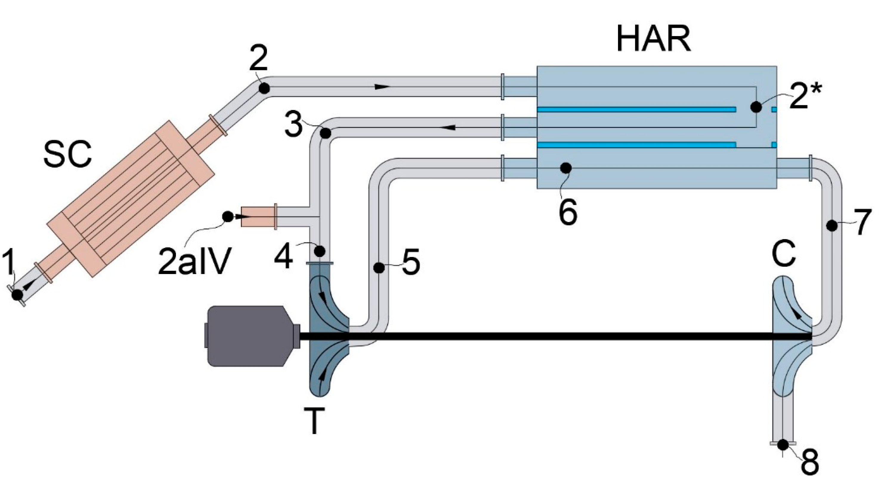
Figure 5.
Cycle of the unit in h-s coordinates.

Figure 6.
Sankey diagram for the modified scheme.


Table 1.
The values of exergy crossing the contour of the basic scheme.
| Index | |||||
|---|---|---|---|---|---|
| 1608 | 293 | 101,325 | - | 0 | |
| 835 | 293 | 101,325 | - | 0 | |
| 15,000 | 293 | 101,325 | 0.00877 | 0 | |
| 453.6 | 293 | 101,325 | 0.00877 | 0 | |
| 12,000 | 293 | 101,325 | 0.00877 | 0 | |
| 557 | 293 | 101,325 | - | 0 | |
| - | - | - | - | 120 | |
| - | - | - | - | 32 | |
| - | - | - | - | 75 | |
| - | - | - | - | 2.5 | |
| - | - | - | - | 3 | |
| - | - | - | - | 3 | |
| - | - | - | - | 40 | |
| - | - | - | - | 120 | |
| 1608 | 293 | 101,325 | - | 0 | |
| 395.5 |
Table 2.
The value of exergy crossing the contour of the modified scheme.
| Index | |||||
|---|---|---|---|---|---|
| 33.6 | 293 | 101,325 | - | 0 | |
| 8.4 | 293 | 101,325 | - | 110.8 | |
| 12,000 | 293 | 101,325 | 0.00877 | 0 | |
| 18,097 | 293 | 101,325 | 0.00877 | 0 | |
| 2243 | 293 | 101,325 | 0.00877 | 0 | |
| 1188 | 293 | 101,325 | 0.00877 | 0 | |
| 2442 | 293 | - | - | 0 | |
| 6516 | 291 | 101,325 | - | 0 | |
| - | - | - | - | 3 | |
| - | - | - | - | 120 | |
| - | - | - | - | 7.6 | |
| - | - | - | - | 0.2 | |
| - | - | - | - | 385 | |
| - | 626.5 | ||||
| 415.0 |
Publisher’s Note: MDPI stays neutral with regard to jurisdictional claims in published maps and institutional affiliations. |
© 2021 by the authors. Licensee MDPI, Basel, Switzerland. This article is an open access article distributed under the terms and conditions of the Creative Commons Attribution (CC BY) license (http://creativecommons.org/licenses/by/4.0/).
Share and Cite
MDPI and ACS Style
Levchenko, D.; Manzharov, A.; Artyukhov, A.; Artyukhova, N.; Krmela, J. Comparative Exergy Analysis of Units for the Porous Ammonium Nitrate Granulation. Energies 2021, 14, 280. https://doi.org/10.3390/en14020280
AMA Style
Levchenko D, Manzharov A, Artyukhov A, Artyukhova N, Krmela J. Comparative Exergy Analysis of Units for the Porous Ammonium Nitrate Granulation. Energies. 2021; 14(2):280. https://doi.org/10.3390/en14020280
Chicago/Turabian StyleLevchenko, Dmytro, Andrii Manzharov, Artem Artyukhov, Nadiya Artyukhova, and Jan Krmela. 2021. "Comparative Exergy Analysis of Units for the Porous Ammonium Nitrate Granulation" Energies 14, no. 2: 280. https://doi.org/10.3390/en14020280
Note that from the first issue of 2016, this journal uses article numbers instead of page numbers. See further details here.