
Heat Transfer in Highly Turbulent Separated Flows: A Review

Laboratory of Thermal and Gas Dynamics, Kutateladze Institute of Thermophysics, Siberian Branch of Russian Academy of Sciences, 630090 Novosibirsk, Russia
Energies 2021, 14(4), 1005; https://doi.org/10.3390/en14041005
Submission received: 4 January 2021
/
Revised: 29 January 2021
/
Accepted: 9 February 2021
/
Published: 14 February 2021
(This article belongs to the Special Issue Enhancement of Heat Transfer in Power Plants)
Abstract
:The study of flows with a high degree of turbulence in boundary layers, near-wall jets, gas curtains, separated flows behind various obstacles, as well as during combustion is of great importance for increasing energy efficiency of the flow around various elements in the ducts of gas-dynamic installations. This paper gives some general characteristics of experimental work on the study of friction and heat transfer on a smooth surface, in near-wall jets, and gas curtains under conditions of increased free-stream turbulence. Taking into account the significant effect of high external turbulence on dynamics and heat transfer of separated flows, a similar effect on the flow behind various obstacles is analyzed. First of all, the classical cases of flow separation behind a single backward-facing step and a rib are considered. Then, more complex cases of the flow around a rib oriented at different angles to the flow are analyzed, as well as a system of ribs and a transverse trench with straight and inclined walls in a turbulent flow around them. The features of separated flow in a turbulized stream around a cylinder, leading to an increase in the width of the vortex wake, frequency of vortex separation, and increase in the average heat transfer coefficient are analyzed. The experimental results of the author are compared with data of other researchers. The structure of separated flow at high turbulence—characteristic dimensions of the separation region, parameters of the mixing layer, and pressure distribution—are compared with the conditions of low-turbulent flow. Much attention is paid to thermal characteristics: temperature profiles across the shear layer, temperature distributions over the surface, and local and average heat transfer coefficients. It is shown that external turbulence has a much stronger effect on the separated flow than on the boundary layer on a flat surface. For separated flows, its intensifying effect on heat transfer is more pronounced behind a rib than behind a step. The factor of heat transfer intensification by external turbulence is most pronounced in the transverse cavity and in the system of ribs.
1. Introduction
In the literature, there are many publications dealing with the study of laminar and turbulent boundary layers under conditions of increased turbulence of the incoming flow in the channels, for example, the monograph [1,2] and papers [3,4,5,6,7,8,9,10,11,12,13,14]. In most papers, biplanar grids and perforated plates were used as turbulators. Homogeneous and isotropic turbulence with a turbulence level of no more than 10% was generated at some distances behind them. According to [6,9], the main influence of external turbulence on the turbulent layer is observed during the bursting process in the outer boundary of the viscous sublayer (y+ < 100), where most turbulent energy is generated. This leads to a stronger impact of external turbulence on heat transfer than on friction. This conclusion is confirmed in the experiments of [15,16], where it was shown that the thickness of the thermal layer under conditions of external turbulence can change very strongly, while the dynamic characteristics remain almost unchanged. Nevertheless, for the turbulence generators mentioned above, their intensifying effect on friction and heat transfer in the boundary layer does not exceed 10–15%. A stronger influence was achieved in [11] in a jet turbulator, where air jets were injected crosswise along the frame perimeter with a certain step. However, the strongest effect was noted in [12,13] for a free jet, although anisotropy of turbulence in it was noted. It is interesting that in some publications (for example, in [10]), it was noted for laminar boundary layers that external turbulence in the transitional regime, instead of the Tollmien–Schlichting instability characteristic of natural turbulence, causes the Kelvin–Helmholtz instability, which leads to the so-called upper bypass transfer [6,17].
When using high-enthalpy flows of porous and slotted curtains [18,19,20,21] to protect surfaces from the destructive effect, high pulsations in the main flow impair their efficiency significantly. Additionally, the protective properties of injection on the most porous and ablating surfaces in highly turbulized flows are reduced [20].
It is shown in the studies of separated flows that turbulence of the incoming flow has a more noticeable effect on them than on the boundary layers. At the same time, it is not correlated with high turbulence induced in the shear layer of the separated flow [22,23,24,25,26,27]. Below is a comparison of some characteristics of separated flows behind various, mainly single obstacles with increased external turbulence.
The study of a separated flow under conditions of high turbulence in a flow around a transverse cylinder is of considerable interest [28,29,30,31,32,33,34,35]. The structure of the flow and heat transfer of the cylinder have their own peculiarities and are fundamentally different from the flow around a backward step and a single rib. This requires a detailed study of the processes of heat and mass transfer. At the same time, from the viewpoint of practical applications, the aerodynamics and heat transfer of a cylinder represent an urgent problem in various technical applications, for example, in the case of a turbulized flow around chimneys [31], leading edges of gas turbine blades [33], etc., therefore, in the review, attention is also paid to this problem.
2. Heat and Mass Transfer and Friction in a Strong Turbulated Flow around a Flat Plate
2.1. Transport Processes in a Laminar Boundary Layer in a Flow with Intense Velocity Pulsations
The problem of the external turbulence effect on transfer processes in boundary layers exists only for relatively constrained channels. The most detailed study of the laminar boundary layer under conditions of external turbulence was carried out in [2]. The turbulence intensity, calculated by longitudinal velocity pulsations, varied from 0.3 to 9%. For turbulence degree Tu0 = 9%, the authors have obtained a very strong increase in the boundary layer thickness, by about 65% in comparison with a low-turbulent flow. Moreover, the greater an increase in δ/x is, the larger the value of Tu0 and the Reynolds number Rex are. An increase in the degree of turbulence of the external flow leads to noticeable deformation of the velocity profile both near the wall and at the outer border of the boundary layer. The velocity profile becomes more gently sloping, the shear stresses on the wall increase with a simultaneous thickening of the boundary layer and intensive erosion of its external boundary. The shape of the velocity profile approaches the turbulent velocity profile. However, the idea that, under the influence of external turbulence, the laminar velocity profile transforms directly into a turbulent one is erroneous. There is no region of the logarithmic law and the region with the viscous regime (/u* = u*y/ν) transforms through the buffer region to the external flow: . In the general case, such a profile is not self-similar in terms of the Reynolds number; this relates especially to the outer part of the boundary layer. This is connected, on the one hand, with selective penetration of turbulent pulsations into the boundary layer from outside, and, on the other hand, with development of turbulent pulsations inside the boundary layer before the laminar-turbulent transition. Taking these features into account, the authors called such boundary layers the pseudo-laminar ones. It was also shown that if the thickness of the boundary layer is set according to the condition δ = 0.99·0, then an intermediate region, called the overlayer where significant changes in the velocity pulsation components are observed, can be distinguished between the external flow and the external border of the boundary layer. The length of the overlayer for different components differs: for the longitudinal component, it is 0.2 δ, for the tangential component, it is 0.3–0.5 δ, and for the component normal to the surface, it can exceed 10 δ. External turbulence has a significant effect on friction and heat transfer in the laminar boundary layer, and the strongest effect (up to 40%) is observed at a high Rex number. To generalize the experimental data on friction and heat transfer coefficients, in addition to the generally accepted Prandtl and Reynolds similarity numbers, Dyban and Epik [2] proposed to use the effective Reynolds number of turbulence at the external border of the boundary layer Reff = νeff/ν, where νeff is the effective kinematic viscosity at the beginning of laminar-turbulent transition. This parameter is quite physically justified, since it characterizes the development of velocity pulsations in the boundary layer. At that, pulsations in the pseudo-laminar boundary layer cannot exceed the level of pulsations corresponding to the beginning of the laminar-turbulent transition. However, from a practical point of view, the use of the proposed parameter is not always possible.
2.2. Effect of External Turbulence on Laminar-Turbulent Transition
To calculate the transfer coefficients in a turbulent boundary layer, it is necessary to know the parameters of the laminar-turbulent transition as accurately as possible. On a smooth wall in a gradientless flow, the Reynolds number of the transition beginning is Re = 2 × 10⁶, and at the end of transition, it reaches Re = 107. The flow in the tube can become turbulent if Red > 2000. However, if the inlet to the tube is ideally smooth and the environment is almost stationary, then the laminar flow can be maintained up to Red = 50,000. The onset of transition depends on the stability of the initial laminar flow to external perturbations. The flow is unstable if the perturbation energy grows faster than its loss due to viscous dissipation.
An increase in the degree of turbulence of the external flow causes a decrease in the transition length. It is shown in [7,8,36,37] that when turbulence intensity changes from 0 to 1% and from 3 to 6%, the Reynolds number of transition decreases from 2 × 10⁶ to 5.7 × 10⁵ and from 1.4 × 10⁵ to 9 × 10⁴, respectively. In [2], a formula for the Reynolds number calculated by momentum loss thickness at a point, where the transition begins, was proposed on the basis of experimental data:
It can be seen from Equation (1) that at a high degree of turbulence, the Reynolds number of the transition beginning reaches the minimum limiting value of 190, which is only 16% higher than the theoretical minimum value ReH** = 164∙(Rex = 3 × 10⁴) [38]. It is interesting that in [12] at Tu0 = 55% a smaller transition number Rex = 2.5 × 10⁴ was obtained. Perhaps, this is due to the fact that in their experimental studies an unfavorable pressure gradient could form on the surface.
In some papers, for instance in [17], it was noted that for laminar boundary layers, external turbulence in the transient regime causes the Kelvin–Helmholtz instability and not the Tollmien–Schlichting instability, characteristic of natural turbulence, which causes the so-called upper bypass transition.
2.3. Friction and Heat Transfer in the Turbulent Boundary Layer at an Increased Level of Turbulence of the External Flow
For a long time, it was believed that the influence of external turbulence on characteristics of turbulent boundary layers is less significant than for laminar layers. However, the researchers in [9] refuted this statement clearly. We will not go into the initial discussions on this issue. At present, in accordance with [6], it is accepted that for the flows behind biplanar grids, which make it possible to increase the degree of turbulence from 3 to 10%, the law of friction and heat transfer can be represented as: St/St0~cf/cf0 = 1 + A Tu0, where A is constant and in accordance with [4] A = 5 or A = 1/(Leu/δ + 2) [5] (the dissipative scale of turbulence is taken into account) or A = 1/(1 + 3 exp(−Re**/400) [3] (the Reynolds number calculated by the thickness of momentum loss is taken into account). To take into account both effects, the law for friction and heat transfer is used:
where α = Leu/δ + 2 and β = 3 exp(−Reθ/400) + 1.
St/St0~Cf/Cf0 = 1 + Tu0/(α β)
A stronger influence of superimposed external pulsations was obtained, for example, in [10] for a jet turbulator, where jets are used in grids instead of bars, and for a flag turbulence generator, where polyethylene strips are tied to a biplanar lattice. The turbulence level Tu0 behind these turbulators reaches 10–20%. At that, there is a large discrepancy between the data and above dependences. Particularly strong deflection takes place at a high level of turbulence in a free jet [11,12,13,14]. The jets are characterized by non-isotropic turbulence and at initial jet calibers, the degree of turbulence can reach 65%. In this case, the Stanton number can increase by up to four times. For these conditions, albeit with large scattering, (St − St0)/St0 ~ Tu0. In the case of jet flowing around a wall at Tu0 = 15%, strong dissimilarity of the velocity and temperature profiles in a turbulent boundary layer was found in [12].
If the velocity profiles in universal coordinates almost correspond to the velocity profiles in a low-turbulent flow, then the temperature profiles are strongly deformed, and the logarithmic region and the vortex wake region disappear. In this regard, the effect of external turbulence on heat transfer is much more noticeable than on friction. The authors of [9] believe that this is due to the influence of external pulsations on coherent structures in the boundary layer, with the formation of streaks in the viscous sublayer and horseshoe-shaped or hairpin vortices, propagating into the outer region, in the logarithmic region. The process of “bursting”—quasi-periodic emissions of matter from the near-wall layers into the environment—in turbulized flows requires further careful study.
2.4. Effect of Increased Turbulence on the Transfer Processes Near a Porous Surface
The flow of matter fed to a turbulent boundary layer through a porous or ablating surface, in contrast to external turbulence, leads to a decrease in the processes of momentum and heat transfer. As it is shown in [18], external turbulence degrades the efficiency of porous cooling. At intense injection parameters, an edging layer appears on the porous surface; in its structure, it differs significantly from the flow in a standard turbulent boundary layer. This layer retains the features characteristic of the injected gas flow. The boundary between the edging layer and the boundary layer is intermittent. External turbulence leads to later formation of the edging layer. With an increase in the degree of turbulence from 0.2 to 11%, the critical injection parameter increases by 1.5 times, and at moderate injection, twofold intensification of heat transfer is observed.
3. Highly-Turbulent Flow around a Backward-Facing Step and a Single Rib
It is shown in studies of separated flows [22,23,24,25,26,27,35,36,39,40,41,42,43,44,45,46,47] that turbulence of the incoming flow has a more noticeable effect on them than on the boundary layers. Moreover, it is not correlated with high turbulence induced in the shear layer of the separated flow [26]. Below, there is a comparison of some characteristics of separated flows behind various obstacles with increased external turbulence.
3.1. Dimensions of Separation Zone in a Turbulized Flow
The greatest attention in the literature is paid to two cases of separated flow formation: the flow behind a backward step and behind a straight rib [48,49,50,51,52,53,54,55,56,57,58,59,60,61,62,63,64,65]. The flow patterns are shown in Figure 1. The main geometric parameter of such flows is the ratio of the obstacle height to the channel size H/S. The rib thickness is usually assumed to be negligible.
These flows are currently classical, and they have a number of both common and very different characteristics. Both of them have a fixed separation point, flow recirculation zone (x < x < xR), reattachment point at x = xR, and relaxation region (x > xR). However, the flow structures in these two cases are very different: if for a step the region of flow disturbance practically does not exceed its height (Figure 1a), then for the rib the disturbances created by the upper rib penetrate deeply into the liquid flow (Figure 1b). The dimensions of the recirculation zone, for the above reasons, during separation behind the rib and the step differ greatly from each other, which also affects the convective heat transfer and hydraulic losses.
3.1.1. Flowing around Backward-Facing Steps
The structure of separated flow is extremely complex. Large-scale coherent structures of the shear layer, which generate a high level of turbulent pulsations and periodic oscillations of the mixing layer and reattachment point, play a specific role.
With natural turbulence, the length of the separation region behind the step depends on the degree of expansion and axisymmetry of the channel, and it varies from 6 to 9 calibers of the step height. Reduction in separation zone behind the step with an increase in the degree of turbulence according to data of different authors is shown in Figure 2.
The tendency to a decrease in the length of separation region depending on the degree of turbulence in mentioned publications is almost the same. Similar results were obtained in works [24,25] and the work of the authors [26].
External turbulence leads to some increase in the mixing layer due to the lower boundary, which is caused by reduction in the separation region. A step on a plate behind a conical leak with several opening angles is considered in [25]. In this work, it is shown that for Tu0 = 10% when flowing around a cone with a right angle, the thickness of the mixing layer behind the attachment point increases by 1.2 times.
Researchers [24] have demonstrated an increase in maximum turbulence from 10 to 12% in the mixing layer behind a 40 mm step at Tu0 = 7.4%. However, it is this small increase in the turbulence intensity that provides a two-caliber reduction in the separation region. In [26], the perforated and flag turbulators were used to create a more noticeable effect of external turbulence. The latter allowed generation of up to 15% turbulence in front of the obstacle causing separation (see Figure 3).
The results obtained in [1,23,42,47] on the reduction in the separation region length (Figure 3) and profiles of the velocity and intensity of turbulence correlate with the data of [24]. As far as the structure of the secondary vortex zone is mainly determined by ejection from the region of the main reversible flow, at high turbulence, it undergoes a change: it is halved, and the corner vortices break up into a series of smaller vortices.
3.1.2. Flowing around Single Ribs
When flowing around a rib, the additional separation in front of it increases the mixing zone significantly. According to [26,27,47], the upper boundary of this zone can be three times the rib height. An increase in external turbulence up to Tu0 = 13.4% at the same height of the obstacle leads to a more significant reduction in the separation zone behind the rib as compared to the step [26,47].
The reduction reaches 20%, while behind the step, it is no more than 13%. In this case, a highly turbulent external flow also causes two-fold reduction in the secondary vortex region behind the rib, like behind the step, almost without changing in the vortex formation pattern. The line of attachment along the channel span is a curved line with convex in the center downstream.
At high external turbulence, the attachment line becomes straighter. The degree of turbulence in the mixing layer behind the rib (Figure 4), as well as behind the step, increases insignificantly. The change in the maximum velocity of the return flow in the recirculation zone of the separated flow behind the backward-facing step and the rib is demonstrated in Figure 5. As it can be seen, the max value behind the rib is two times higher than behind the step, and this is one of the reasons for the greater intensification of heat transfer when using ribs. At the same time, in accordance with Figure 5, there is a slight increase in the maximum return flow rate for a highly turbulized flow. However, there is a strong relationship between the coherent structures of the mixing layer and reverse flow.
The location of the maximum of turbulent pulsations on the coordinate plane is presented in Figure 6 for two types of obstacles in the middle of the mixing layers. It can be clearly seen there that the mixing layer is much larger behind the rib. As it is shown for the step, with increasing Tu0, the middle of the mixing layer approaches the obstacle.
3.2. Pressure Fields behind Single Rib and Step
Increased external turbulence has a much stronger effect on the displacement of the pressure coefficient maximum to the obstacle than the length of the attachment region and increases the absolute value of the wall pressure coefficient. The results of measurements of distribution of pressure coefficient Cp = 2(pi − p0)/ρ02 for the flow around the rib and the step are shown in Figure 7. There is a fundamental qualitative and quantitative difference between these two flow cases.
Experimental data on the pressure coefficient, presented in universal coordinates = f(X/XR), are shown in Figure 8. Here, XR is the coordinate of the attachment point of the separated flow.
According to Figure 8, pressure distributions over the surface behind the separation point in universal coordinates are generalized for the ribs with different heights and different degrees of external turbulence. When flowing around the steps, such generalization was not obtained, which indicates a possible effect of the flow prehistory on the flow behind the step. The separation in front of a rib destroys the effect of the initial conditions.
3.3. Temperature Profiles behind Single Obstacles
The profiles of velocity and temperature in the flow detached behind an obstacle in usual coordinates at high external turbulence have qualitatively the same shape as the profiles under the conditions of low-turbulent flow. At the initial distances from the obstacle, the wall has a region of negative velocities, which decreases to zero while approaching the point of attachment.
The mixing layer width expands as it moves from the step or rib, and accordingly, the velocity gradients in the normal direction to the wall decrease. For turbulized flows, mixing processes occur more intensively, and velocity profiles become steeper. Since the friction coefficient is zero at the point of shear layer attachment, the universal coordinates for the profiles of separated flow velocity and temperature are rarely used, mainly in the zone of relaxation.
The mixing layer width expands as it moves from the step or rib, and accordingly, the velocity gradients in the normal direction to the wall decrease. For turbulized flows, mixing processes occur more intensively, and velocity profiles become steeper. Since the friction coefficient is zero at the point of shear layer attachment, the universal coordinates for the velocity and temperature profiles in separated flows are rarely used, mainly in the relaxation zone.
Due to violation of the Reynolds analogy for separated flows, the heat transfer coefficient at the attachment point is maximal and can be applied to construct altered universal coordinates. The temperature profiles for a low-turbulent flow around a step in such coordinates do not have a logarithmic section characteristic of a flat plate [41], although they do not have negative values near the wall, and for a rib (Figure 9a), the profiles near the barrier and in the relaxation areas coincide with the profiles on the plate.
Figure 9b shows characteristic temperature distributions behind a backward-facing step in coordinates [26]:
Lines 1 and 2 in Figure 9 correspond to the temperature distribution in the laminar sublayer ϕ = η and in the turbulent core of the ordinary boundary layer ϕ = 2.5·ln η + 5.5. A specific section of the logarithm, which is not universal and varies from section to section downstream, can be traced in the separated flow. The largest decrease in the logarithmic section occurs in the middle of the separation bubble: in a low-turbulent flow at x/H = 4.65 and for turbulence Tu0 = 13.4% at x/H = 2.75. At Tu0 = 13.4%, the relative temperature distribution demonstrates more significant stratification of experimental data in the outer logarithmic region for different cross-sections along the separation region than at low turbulence. A similar picture is observed for the rib [26,47]. Increased turbulence of the main flow lowers the overall level of relative temperature ϕ, indicating, in general, intensification of heat transfer processes.
3.4. Heat Transfer Enhancement
Heat transfer intensification behind a rib and a step in a turbulized flow (Tu0 = 13.4%) was noted in [42,47] (Figure 10); it was most pronounced at the point of shear layer attachment, where the maximum of α occurs.
The relative heat transfer coefficients are considered in Figure 11 for obstacles with a height of 3 to 30 mm, which characterize the effect of turbulence. The effect of Tu0 for a rib and a step appears somewhat differently. For a rib with high turbulence due to the shift of the heat transfer maximum to the obstacle, intensification near the rib is more pronounced for high obstacles, while in the relaxation region, on the contrary, it is more pronounced for small obstacles. The effects of turbulence persist far downstream. Near a step, the effectiveness of the highest obstacle decreases. Nevertheless, dependence of the Nusselt number, plotted along dividing line L = (XR2 + H2)1/2, on the Reynolds number under real circumstances is described by the formula from [66] (Figure 12):
NuL = 0.192 ReL0.665 Pr1/3; at a high degree of turbulence, it is described by a similar empirical formula of Leontiev et al. [67] NuL = 0.0803 ReL0.73 Pr1/3.
Behind the step with an inclined rear wall, dependence of heat transfer in the separation region on external turbulence remains with a change in the angle, with the exception of small angles of continuous flow. This can be seen in Figure 13 according to the maximum values of Nusselt number. Here are the results of experimental research works [26,43].
4. Flow and Heat Transfer behind an Inclined Rib at High Turbulence
For additional intensification of heat transfer, the ribs on the heat exchanger surfaces are mounted at an angle to the gas flow. This method of heat transfer enhancement is often implemented inside the blades of gas turbines, when cooling electronic devices, and in compact heat exchangers. A diagram of such a task is shown in Figure 14.
For a transverse rib, the longitudinal pressure distributions in all cross-sections along the channel width are similar; therefore, due to the three-dimensional character of the flow behind the beveled rib, there is no such coincidence. As it is shown in Figure 15, the flow behind the inclined rib is inhomogeneous along the transverse coordinate z, which also affects the distribution of the heat transfer coefficient. The largest pressure drop behind the rib along the channel width is observed near the acute rib inclination relative to the wall [39,65]. In this case, the maximum vacuum occurs, advanced by the pressure recovery. For turbulence Tu0~15%, the reduced relative pressure coefficient in the midsection becomes higher when the angle of rib inclination relative to the flow ϕ decreases. For ϕ = 50°, this rise is 35%.
When flowing around a rib oriented at an angle to the flow, the greatest intensification of heat transfer in the separation region is observed at rotation angle ϕ = 70° (Figure 16a). Moreover, low ribs are more effective (Figure 16b), and the effect of heat transfer enhancement due to high turbulence is significant at any rib height.
5. Heat Transfer in a Cavity during Flow Turbulization
Heat exchangers of power plants often have transverse trenches (cavities) on their surfaces. It can have a rectangular shape or be in the form of trapeziums with an angle of inclination from the wall ϕ. A diagram of a cavity with inclined side walls is shown in Figure 17.
Heat transfer inside the cavity depends strongly on its depth H, and as it increases, convective heat transfer decreases. For this reason, a transverse cavity is not a heat transfer enhancer, and integral heat transfer from the cavity surface is always lower than on the smooth wall. Considering that the cavity walls make different contributions to integral heat transfer, it is important to analyze the behavior of the pressure and heat transfer coefficient in individual sections of the cavity.
The main contribution to heat transfer and hydraulic losses is made by the downstream sidewall. This clearly follows from Figure 18, which shows the pressure distribution in the median section over the entire sweep of the cavity. On the downstream wall, the pressure, depending on the angle of inclination, can change its sign, and for cavities with gentle walls (small values of angle ϕ), the value of Cp increases strongly.
The heat transfer coefficient inside the cavity changes in the same way as the pressure coefficient (Figure 19). Its value is maximum on the back wall and minimum on the front. This tendency is observed in a wide range of variations in turbulence intensity. It is important to emphasize that the effect of turbulence on heat transfer is significant, which is probably caused by penetration of large-scale pulsations from the external turbulized flow into the cavity.
With an increase in the degree of main flow turbulence Tu0, a gradual uniform increase in heat transfer in the transverse cavity is observed, mainly on the back wall [44]. The degree of heat transfer enhancement in a cavity with different opening angles of the side walls differs, which is associated with peculiarities of vortex formation for each angle. A more noticeable increase in heat transfer occurs at angles φ = 60 and 70°, for which flow instability is noted. That is, the effect of external turbulence reaches 40%, which is generally greater than that behind the rib and the step. The character of distribution does not change with increasing Tu0. This confirms uncorrelatedness of external turbulence and turbulence of the separated shear layer, which was indicated in [22].
The effect of intensifying heat transfer inside the cavity at different levels of external turbulence is shown in Figure 20. The Nusselt number Nuav90Tu = 1.5% is used here as the scale of heat transfer, which corresponds to the average heat transfer in a rectangular trench (ϕ = 90°) and at a natural degree of turbulence (Tu0 = 1.5%).
As expected, an increase in turbulence intensifies heat transfer at all inclination angles of the cavity side walls. At the same time, it should be specially noted that the greatest effect is achieved in cavities with an inclination angle ϕ = 60 degrees and the degree of intensification increases almost twice. The weakest effect can be observed in rectangular cavities. These results are important from the viewpoint of practical applications.
Therefore, with an increase in the degree of main flow turbulence Tu0, a gradual uniform increase in heat transfer in the transverse cavity is observed, mainly on the rear wall [44]. The degree of heat transfer intensification in a cavity with different opening angles of the side walls differs, which is associated with peculiarities of vortex formation for each angle. A more noticeable increase in heat transfer occurs at angles φ = 60° and 70°, for which flow instability is noted. That is, the effect of external turbulence reaches 40%, which is generally greater than that behind the rib and the step. The character of distribution does not change with increasing Tu0. This confirms uncorrelatedness of external turbulence and turbulence of the separated shear layer, which was indicated in [22].
It is necessary to dwell on the interesting results of [45]. As shown in this work, intensification of average heat transfer by external turbulence on a surface densely covered with hemispherical cavities was studied. With a hole diameter of 16 mm, the distance between the nearest hole centers is 19 mm. In a channel 76 mm high without a turbulator, intensification of heat transfer when using holes was 44% in comparison with a smooth surface. However, behind the turbulizing grid at Tu0 from 8 to 6%, the heat transfer efficiency when using holes decreased to 35%. At first glance, the resulting effect is quite unexpected. Most of all, this is due to the fact that the greatest intensification of heat transfer on the surface when using spherical notches corresponds to the transient regime, but not to the beginning of the turbulent flow regime in dimples, and additional turbulization of the flow reduces heat transfer.
6. Heat Transfer in the Ribs System
The scenarios considered above for the development of dynamic and thermal fields in the flow around single obstacles are the model ones, and they help to understand better the physics of exchange processes. In real heat exchanging devices, systems of alternating ribs are used to intensify heat transfer. Depending on the specific conditions, they are located at certain distances from each other, as it is shown in Figure 21. The ribs can also be set at an angle to the flow.
Flow visualization [40] showed that in the case of a low-turbulent flow around an assembly of three or more high ribs (H = 60 mm), a highly unstable flow can be seen in the second cell; it is associated with mass suction from next cell because of the low pressure behind the second rib and a reverse flow over the third rib (Figure 22).
Thus, a multi-ribbed structure can be regarded as a feedback system, when the flow and heat transfer in the cell in front depends on how many cells are located after it. This interesting and unusual phenomenon is caused by the interference effects of separated flows behind each obstacle and requires extensive study, since it can have a strong effect on aerodynamic drag and heat transfer.
At high incident flow turbulization, instability moves to the first cell. When flowing around five ribs, heat transfer in a low-turbulent flow reaches a maximum in the last two cells, and in accordance with the character of vortex formation, the strongest heat transfer intensification of up to 30%, caused by external turbulence, is observed in the second cell (Figure 23).
7. High-Turbulent Flow around a Cylinder
7.1. Features of the Flow around a Circular Cylinder
The cross flow around a cylinder is a typical example of a separated flow on a curved surface. It is known that in a laminar flow at angle φ > 80° the flow separates. In a turbulent flow, a more intense momentum transfer occurs; as a result, the turbulent flow has a greater ability to resist an increasing positive pressure gradient and friction. Therefore, flow separation occurs at noticeably higher values of φ than in the case of a laminar flow. The separation point in the turbulent flow around a circular cylinder corresponds to φ~110°. A wake is formed behind the separation point, where a reverse flow and vortices are formed. Since the separation point of the laminar flow is located upstream than that of a turbulent flow, the size of the wake in the first case is larger, and accordingly, the total resistance increases. As the Reynolds number increases, the three-dimensional vortex pattern interacting with the external flow—the so-called Karman vortex street—becomes more and more unsteady. Namely, this phenomenon is the key to understanding the results of observations by numerous researchers.
Richardson was one of the first who draw attention to the fact that the laws of heat transfer at the front of the cylinder are different from the laws for the separated flow for the back part of the cylinder [46]. He found out that at a turbulent flow around a cylinder, the heat transfer coefficient in the separation zone is proportional to the Reynolds number to the power of 2/3. This law of heat transfer has been confirmed for many cases of separated flows in a turbulent flow (in a tube with sudden expansion, in sufficiently deep caverns, etc.), where turbulence is maintained by diffusion transfer from regions far from the wall.
7.2. Flow around a Circular Cylinder with Increased Turbulence of the External Flow
According to [2], in both the laminar and turbulent flows around the cylinder external turbulence has the strongest effect on the parameters in the separation zone. With an increase in Tu0, a decrease in rarefaction in the separation region is observed; the mixing layer thickens as well as the width of the wake along the flow. The intensity of pulsations of the longitudinal velocity component also increases. In this case, the frequency of detachment of regular vortices from the rear part of the cylinder almost does not change. That is, all spectra have a peak at a frequency corresponding to the Strouhal number equal to 0.2. However, the peak amplitude decreases (almost twice at Tu0~24%). This indicates a decrease in the energy contained in regular vortices. It was shown in [2] that turbulence of the external flow leads to an increase in the values of turbulent shear stresses and kinetic energy of turbulence in the inner part of the near wake. Both factors intensify the flow in the reverse flow zone, increase the degree of turbulence there, and cause an increase in the turbulent viscosity in the wake. For the resistance coefficient, the following formula is proposed:
CW = CW0 (1 − 1.2 Tu00.6)
At low degrees of turbulence, the resistance coefficient decreases noticeably, and at high Tu0, it becomes close in the absolute value to the CW0 value for a supercritical flow around a cylinder, when a turbulent boundary layer develops on its surface and separates.
7.3. Heat Transfer in a Turbulized Flow around a Cylinder
According to provisions of [2], in the range of Tu0 = 0.3–27% and Re = 2 × 10³ − 8 × 10⁴, the subcritical nature of the flow around the cylinder is preserved. For these conditions, distributions of local heat transfer coefficients are characterized by a decrease in the heat transfer coefficients from the front critical point downstream in the region of a developed laminar boundary layer and a subsequent increase beyond the separation point towards the rear critical point. The curve Nu = f(Re) has a minimum near the point of separation of the laminar boundary layer and two maxima at the frontal and rear points (φ = 0 and φ = 180°). Moreover, at high external turbulence, the frontal surface of cylinder makes the greatest contribution to total heat transfer, while at a low degree of turbulence, with an increase in the Reynolds number, the role of the back part increases.
For the average Nusselt number, the Zukauskas formula [34] is recommended in [2]:
Nuave = 0.23 Re0.6 Tu00.15
In [35], the authors showed that the initial point of flow stall depends on the ratio of the longitudinal scale of turbulence to the cylinder diameter. The smaller the ratio, the earlier the separation occurs. This reduces the pressure and especially heat transfer in the separation region. For the Nusselt number at the rear critical point, the modified Richardson relationship was suggested:
Nu = 0.15 Re2/3 (Λ/D)−0.66
It is considered in [29,68] how external turbulence affects the vortex wake behind a cylinder with different length-to-diameter ratios L/D. It has been determined that increased turbulence has a stronger effect with an increase in the width of the vortex wake and the frequency of vortex separation at lower L/D values.
8. Conclusions
As an introduction to the problem, a brief description of the external flow with an increased level of turbulence around a flat plate is given in the review presented.
The main analysis is aimed at assessing the effect of external turbulence on the dynamics and thermal characteristics of the separated flow behind different obstacles. It is demonstrated that the influence of external small-scale pulsations is ambiguous in comparison with pulsations in shear layers of various separated flows. This confirms the lack of correlation between them.
The intensifying effect of a highly turbulent flow on heat transfer in separated flows is demonstrated. At that, the lower barriers, especially ribs, retain an obvious advantage as heat transfer enhancers. The strongest manifestation of flow turbulence is noted for transverse trenches.
When external turbulence acts on the separated flow around a cylinder, in addition to the level and scale of turbulence, its geometric dimensions play an important role.
Funding
The work was financially supported by the Russian Science Foundation (grant 19–79-30075).
Conflicts of Interest
The authors declare that they have no known competing financial interests or personal relationships that could have appeared to influence the work reported in this paper.
Nomenclature
| Cp = 2(pi − p0)/ρ2 | pressure coefficient |
| dimensionless pressure coefficient | |
| H | obstacle height, m |
| L | dividing line length, m |
| L = | |
| Nu | Nusselt number, Nu = α H/λ |
| P | pressure, Pa |
| Pr | Prandtl number |
| Re | Reynolds number; |
| ReH = H/ν | |
| Tu0 | the degree of turbulence of the main stream, |
| main stream velocity, m/c | |
| x | longitudinal coordinate, m |
| XR | coordinate of the attachment point separated flow |
| α | heat transfer coefficient, W/m2K |
| ϕ | the angle of orientation of the obstacle to the flow or the angle of inclination of the side walls of the trench or step, degrees |
| λ | coefficient of thermal conductivity, W/mK |
| ν | kinematic viscosity, m2/c |
| Indices: | |
| 0 | conditions in the main stream or with natural turbulence |
| max | maximum value |
| min | minimum value |
| w | wall |
References
- Alemasov, V.E.; Glebov, G.A.; Kozlov, A.P. Thermoanemometry Methods for Investigation of Separation Flows; Branch of the USSR Academy of Sciences: Kazan, Russia, 1990. (In Russian) [Google Scholar]
- Dyban, E.P.; Epik, E.Y. Heat Mass Transfer and Hydrodynamics of Turbulized Flows; Naukova Dumka: Kyiv, Ukraine, 1985. (In Russian) [Google Scholar]
- Blair, M.F. Influence of free-stream turbulence on turbulent boundary layer heat transfer and mean profile development, part II-Analysis of the results. J. Heat Transf. 1983, 105, 41–47. [Google Scholar] [CrossRef]
- Simonich, J.C.; Bradshaw, P. Effect of free-stream turbulence on heat transfer through a turbulent boundary layer. J. Heat Transf. 1978, 100, 671–677. [Google Scholar] [CrossRef]
- Hancock, P.E.; Bradshaw, P. The effect of free-stream turbulence on turbulent boundary layers. J. Fluid Eng. 1983, 105, 284–289. [Google Scholar] [CrossRef]
- Peneau, F.; Boisson, H.C.; Djilali, N. Large eddy simulation of the influence of high free-stream turbulence on a spatially evolving boundary layer. Int. J. Heat Fluid Flow. 2000, 21, 640–647. [Google Scholar] [CrossRef]
- Junkhan, G.H.; Serovy, G.K. Effects of free-stream turbulence and pressure gradient on flat-plate boundary-layer velocity profiles and on heat transfer. J. Heat Transf. 1967, 89, 169–176. [Google Scholar] [CrossRef]
- Kestin, J.; Maeder, P.F.; Wang, H.E. Influence of turbulence on the transfer of heat from plates with and without a pressure gradient. Int. J. Heat Mass Transf. 1961, 3, 133–154. [Google Scholar] [CrossRef]
- Kondjoyan, A.; Peneau, F.; Boisson, H.C. Effect of high free stream turbulence on heat transfer between plates and air flows: A review of existing experimental resultants. Int. J. Therm. Sci. 2002, 41, 1–16. [Google Scholar] [CrossRef]
- Thole, K.A.; Bogard, D.G. High freestream turbulence effects on turbulent boundary layers. J. Fluids Eng. 1996, 118, 276–284. [Google Scholar] [CrossRef]
- Young, C.D.; Han, J.C.; Huang, Y.; Rivir, R.B. Influence of jet-grid turbulence on a flat plate turbulent boundary layer flow and heat transfer. J. Heat Transf. 1992, 114, 65–72. [Google Scholar] [CrossRef]
- Maciejewski, P.K.; Moffat, R.J. Heat transfer with very free stream turbulence: Part I—Experimental data. J. Heat Transf. 1992, 114, 827–833. [Google Scholar] [CrossRef]
- Maciejewski, P.K.; Moffat, R.J. Heat transfer with very high free-stream turbulence. Part II—Analysis of results. J. Heat Transf. 1992, 114, 834–839. [Google Scholar] [CrossRef]
- MacMullin, R.; Elrod, W.; Rivir, R.B. Free-stream turbulence from a circular jet on flat plate heat transfer and boundary layer flow. J. Turbomachin. 1989, 111, 78–86. [Google Scholar] [CrossRef]
- Boyarshinov, B.F. Some characteristics of heat and mass transfer in a turbulent air flow over a surface. J. Appl. Mech. Technol. Phys. 2000, 11, 686–691. [Google Scholar] [CrossRef]
- Boyarshinov, B.F.; Titkov, V.I. Effect of free-stream turbulence on the boundary-layer structure with diffusion combustion of ethanol. J. Appl. Mech. Techn. Phys. 2001, 42, 972–978. [Google Scholar] [CrossRef]
- Epik, E.Y.; Grigorenko, V.A. Heat transfer at occurrence of the bypass transition. In Proceedings of the 2nd Russian National Conference on Heat Transfer, Moscow, Russia, 26–30 October 1998; MPEI: Moscow, Russia, 1998; Volume 2, pp. 278–281. (In Russian). [Google Scholar]
- Mironov, B.P.; Vasechkin, V.N.; Mamonov, V.N.; Yarygina, N.I. Transport processes in turbulent boundary layer under high level free stream turbulence. Struct. Turbul. Heat Mass Transf. 1982, 14, 221–243. [Google Scholar]
- Lebedev, V.P.; Lemanov, V.V.; Misyura, S.Y.; Terekhov, V.I. Effects of flow turbulence on film cooling efficiency. Int. J. Heat Mass Transf. 1995, 38, 2117–2125. [Google Scholar] [CrossRef]
- Leontiev, A.I.; Lebedev, V.P. (Eds.) Thermal Protection of Plasmatron Walls; Institute of Thermophysics: Novosibirsk, Russia, 1995; p. 336. (In Russian) [Google Scholar]
- Kutateladze, S.S.; Leontiev, A.I. Heat Transfer, Mass Transfer and Friction in Turbulent Boundary Layer; Hemisphere: New York, NY, USA, 1990. [Google Scholar]
- Dyban, E.P.; Epik, E.Y.; Yushina, L.E. Heat transfer on the surface of longitudinally streamlined bodies in the presence of closed separation and external flow turbulization. In Proceedings of the 10th International Heat Transfer Conference, Brighton, UK, 14–18 August 1994; Taylor and Francis: Abingdon, UK, 1994; Volume 3, pp. 25–30. [Google Scholar]
- Jaňour, Z.; Jonás, P. On the flow in a channel with a backward-facing step on one wall. Eng. Mech. 1994, 1, 313–320. [Google Scholar]
- Isomoto, K.; Honami, S. The effect of inlet turbulence intensity on the reattachment process over a backward-facing step. Trans. JSME 1988, B54, 51–58. [Google Scholar] [CrossRef] [Green Version]
- Suzuki, Y.; Kiya, M. Effect of free-stream turbulence on separated-reattaching flows for different angles of separation. Bull. JSME 1985, 28, 1887–1892. [Google Scholar] [CrossRef]
- Terekhov, V.I.; Yarygina, N.I.; Zhdanov, R.F. Heat transfer in turbulent separated flows in the presence of high free-stream turbulence. Int. J. Heat Mass Transf. 2003, 46, 4535–4551. [Google Scholar] [CrossRef]
- Castro, I.P.; Haque, A. The structure of a shear layer bounding a separation region. Part 2. Effects of free-stream turbulence. J. Fluid Mech. 1988, 192, 577–595. [Google Scholar] [CrossRef]
- Kestin, J.; Wood, R.T. The influence of turbulence on mass transfer from cylinders. J. Heat Transf. 1971, 93, 321–326. [Google Scholar] [CrossRef]
- Szepessy, S. The effect of free stream turbulence on a circular cylinder for various aspect ratios. In Proceedings of the IUTAM Symposium “Bluff-Body Wakes, Dynamics and Instabilities”, Gottingen, Germany, 7–11 September 1992; pp. 96–100. [Google Scholar]
- Torii, S.; Yang, W.-J. Effects of the length scale of free-stream turbulence and cylinder size on local heat transfer in laminar separated flows. Exp. Heat Transf. 1993, 6, 175–187. [Google Scholar] [CrossRef]
- Maneev, A.P.; Terekhov, V.I. Specific features of heat transfer on the external surface of smoke stacks blown by wind. Therm. Eng. 2015, 62, 183–189. [Google Scholar] [CrossRef]
- Sanitjai, S.; Goldstein, R.J. Effect of free stream turbulence on local mass transfer from a circular cylinder. Int. J. Heat Mass Transf. 2001, 44, 2863–2875. [Google Scholar] [CrossRef]
- Thole, K.A.; Radomsky, R.W.; Kang, M.B.; Kohli, A. Elevated free stream turbulence effects on heat transfer for a gas turbine vane. Int. J. Heat Fluid Flow. 2002, 23, 137–147. [Google Scholar] [CrossRef]
- Zhukauskas, A.A.; Zhyugzhda, I. Heat Transfer of a Cylinder in a Cross Flow of a Liquid; Mokslas: Vilnius, Lithuania, 1979. (In Russian) [Google Scholar]
- Al-Asmi, K.; Castro, I.P. Vortex shedding in oscillatory flow: Effects of free-stream turbulence. In Proceedings of the IUTAM Symposium “Bluff-Body Wakes, Dynamics and Instabilities”, Gottingen, Germany, 7–11 September 1992; pp. 123–126. [Google Scholar]
- Terekhov, V.I.; Yarygina, N.I. Heat transfer in separated flows at high levels of free-stream turbulence. In Proceedings of the 14th International Heat Transfer Conference IHTC14, Washington, DC, USA, 8–13 August 2010; Volume 2, p. 22154. [Google Scholar]
- Kestin, J. The Effect of free-stream turbulence on heat transfer rates. Adv. Heat Transf. 1996, 3, 1–32. [Google Scholar]
- Schlichting, H.; Gersten, K. Boundary-Layer Theory, 8th ed.; Springer: Berlin/Heidelberg, Germany, 2000. [Google Scholar]
- Terekhov, V.I.; Yarygina, N.I.; Smulsky, Y.I. Turbulent separated flow behind a flat rib with different orientations relative to the flow. Ind. Heat Eng. 2006, 28, 21–26. [Google Scholar]
- Terekhov, V.I.; Yarygina, N.I.; Smulsky, Y.I. Flow over a system of several ribs under conditions of high free-stream turbulence. Thermophys. Aeromech. 2006, 13, 335–341. [Google Scholar] [CrossRef]
- Shlyazhas, R.B. Turbulent Transfer of Momentum and Heat Transfer Trough a Boundary Layer behind an Obstacle. Ph.D. Thesis, Lithuanian Energy Institute, Kaunas, Lithuania, 1984; 20p. [Google Scholar]
- Terekhov, V.I.; Yarygina, N.I.; Zhdanov, R.F. Enhancing heat transfer in separated flow behind a rib or a back step at high level of free-stream turbulence. In Proceedings of the 3rd International Symposium on Heat Transfer Enhancement and Energy Conservation, Guangzhou, China, 12–15 January 2004; Volume 1, pp. 10–17. [Google Scholar]
- Ota, T.; Sugawara, Y. Turbulent heat transfer on the separated and reattached flow around an inclined downward step. In Proceedings of the 10th International Heat Transfer Conference, Brighton, UK, 14–18 August 1994; Taylor and Francis: Abingdon, UK, 1994; Volume 3, pp. 113–118. [Google Scholar]
- Terekhov, V.I.; Yarygina, N.I.; Dyachenko, A.Y. Turbulent heat transfer in a cross flow cavity with inclined sidewalls. In Proceedings of the 12th International Heat Transfer Conference, Grenoble, France, 18–20 August 2002; Elsevier: Amsterdam, The Netherlands, 2002; Volume 2, pp. 615–621. [Google Scholar]
- Anderson, A.M.; Gauthier, B.M.; Donnellan, K.F. Heat transfer from a dimpled surface with and without free-stream turbulence in a thermally developing flow. In Proceedings of the 12th International Heat Transfer Conference, Grenoble, France, 18–20 August 2002; Elsevier: Amsterdam, The Netherlands, 2002; Volume 1, pp. 375–381. [Google Scholar]
- Richardson, P.D. Heat and mass transfer in turbulent flows. Chem. Eng. Sci. 1963, 18, 149–155. [Google Scholar] [CrossRef]
- Terekhov, V.I.; Bogatko, T.V.; Dyachenko, A.Y.; Smulsky, Y.I.; Yarygina, N.I. Heat Transfer in Subsonic Separated Flows; NGTU: Novosibirsk, Russia, 2018. (In Russian) [Google Scholar]
- Chandrsuda, C.; Bradshaw, P. Turbulence structure of a reattaching mixing layer. J. Fluid Mech. 1981, 110, 171–194. [Google Scholar] [CrossRef]
- Ruderich, R.; Fernholz, H.H. An experimental investigation of a turbulent shear flow with separation, reverse flow, and reattachment. J. Fluid Mech. 1986, 163, 283–322. [Google Scholar] [CrossRef]
- Yang, J.T.; Tsai, B.B.; Tsai, G.L. Separated-reattaching flow over a back-step with uniform normal mass bleed. J. Fluids Eng. 1994, 116, 29–35. [Google Scholar] [CrossRef]
- Adams, E.W.; Johnston, J.P. Flow structure in the near-wall zone of turbulent separated flow. AIAA J. 1988, 26, 932–939. [Google Scholar] [CrossRef]
- Kiya, M.; Sasaki, K. Structure of a turbulent separation bubble. J. Fluid Mech. 1983, 137, 83–113. [Google Scholar] [CrossRef]
- Makiola, B.; Ruck, B. Experimental investigation of a single-sided backward-facing step flow with inclined step geometries. In Engineering Turbulence Modelling and Experiments; Rodi, W., Ganić, E.N., Eds.; Elsevier: New York, NY, USA, 1990; pp. 487–496. [Google Scholar]
- Eaton, J.K.; Johnston, J.P. A review of research on subsonic turbulent flow reattachment. AIAA J. 1981, 19, 1093–1100. [Google Scholar] [CrossRef]
- Baker, S. Regions of Recirculating Flow Associated with Two-Dimensional Steps. Ph.D. Thesis, University of Surrey, Guildford, UK, 1977. [Google Scholar]
- Nakamura, Y.; Ozono, S. The effects of turbulence on a separated and reattaching flow. J. Fluid Mech. 1987, 178, 477–490. [Google Scholar] [CrossRef]
- Cherry, N.J.; Hillier, R.; Latour, M.E.M.P. Unsteady measurements in a separated and reattaching flow. J. Fluid Mech. 1984, 144, 13–46. [Google Scholar] [CrossRef]
- Vlasov, E.V.; Ginevskii, A.S.; Karavosov, R.K.; Frankfurt, M.O. Near-wall pressure pulsations in the flow separation region behind two-dimensional obstacles. Trudy TsAGI 1982, 2137, 3–29. (In Russian) [Google Scholar]
- Driver, D.M.; Seegmiller, H.L.; Marvin, J. Time-dependent behavior of a reattaching shear layer. AIAA J. 1987, 25, 914–919. [Google Scholar] [CrossRef]
- Jovic, S. An Experimental Study of a Separated/Reattached Flow behind a Backward-Facing Step. ReH = 37,000; NASA Technical Memorandum; NASA: Washington, DC, USA, 1996; p. 110384.
- Tani, I.; Iuchi, M.; Komoda, H. Experimental Investigation of Flow Separation Associated with a Step or Groove; Rept. 364; Aeronautical Research Institute, University of Tokyo: Tokyo, Japan, 1961. [Google Scholar]
- Kryukov, V.N. A Study of Turbulent Separation behind a Downward Step, Collection of Topical Scientific Papers, Some Problems on Heat and Mass Transfer between Flows and Surfaces; MAI: Moscow, Russia, 1986; pp. 24–28. (In Russian) [Google Scholar]
- Hillier, R.; Cherry, N.J. The effects of free-stream turbulence on separation bubbles. J. Wind Eng. Ind. Aerodyn. 1981, 8, 49–58. [Google Scholar] [CrossRef]
- Roshko, A.; Lau, J.C. Some Observations on Transition and Reattachment of Free Shear Layer in Incompressible Flow; Stanford University Press: Palo Alto, CA, USA, 1965; pp. 157–167. [Google Scholar]
- Smulsky, Y.I.; Terekhov, V.I.; Yarygina, N.I. Heat transfer in turbulent separated flow behind a rib on the surface of square channel at different orientation angles relative to flow direction. Int. J. Heat Mass Transf. 2012, 55, 726–733. [Google Scholar] [CrossRef]
- Ota, T.; Nishiyama, H.A. Correlation of maximum turbulent heat transfer coefficient in reattachment flow region. Int. J. Heat Mass Transf. 1987, 30, 1193–1200. [Google Scholar] [CrossRef]
- Leontiev, A.I.; Ivin, V.I.; Grekhov, L.V. Semi-empirical method of the estimation of heat transfer in the region of boundary layer deattachment. J. Eng. Phys. 1984, 47, 543–550. [Google Scholar]
- Sak, C.; Liu, R.; Ting, D.S.-K.; Rankin, G.W. The role of turbulence length scale and turbulence intensity on forced convection from a heated horizontal circular cylinder. Exp. Therm. Fluid Sci. 2007, 31, 279–289. [Google Scholar] [CrossRef]
Figure 1.
Flow configuration behind a backward step (a) and a rib (b).
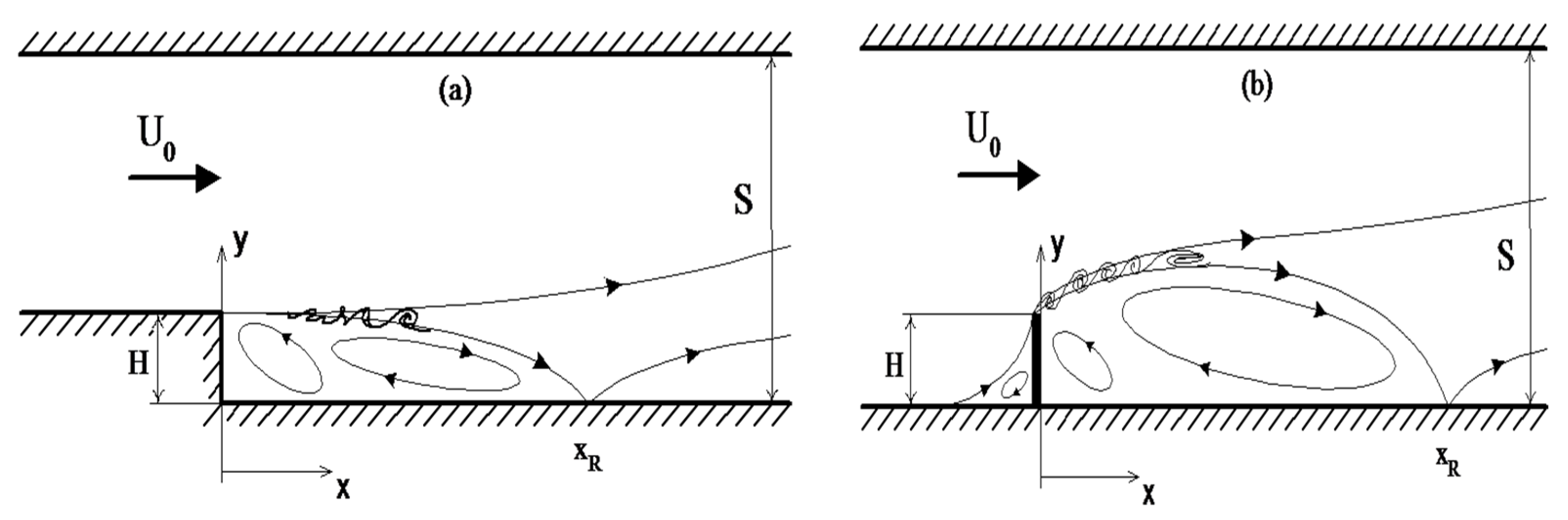
Figure 2.
Influence of turbulence on the length of the separation region behind the step.

Figure 3.
Distribution of turbulence intensity along the center of the channel. The origin X is from the obstacle [26].
Figure 3.
Distribution of turbulence intensity along the center of the channel. The origin X is from the obstacle [26].
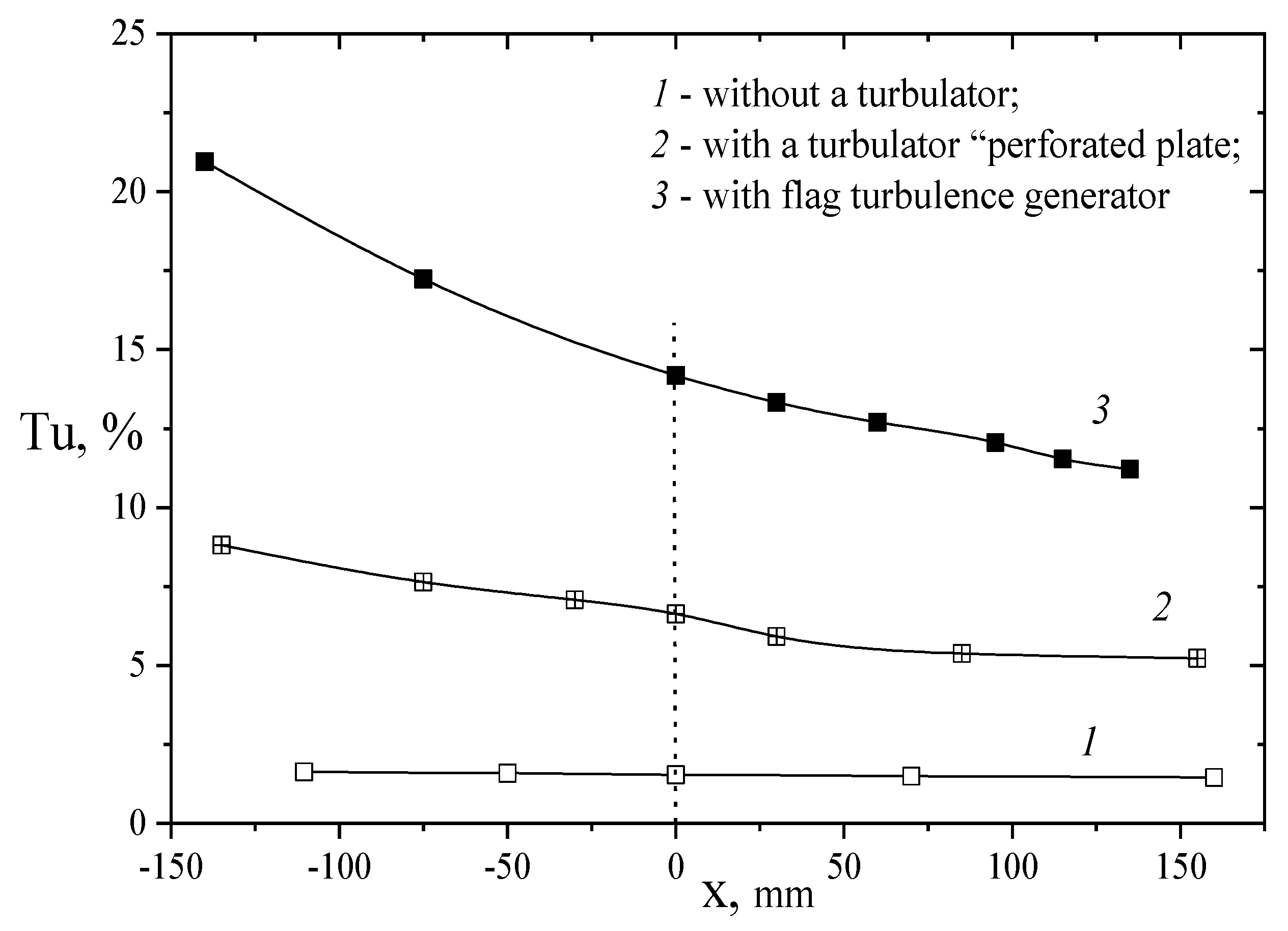
Figure 4.
Turbulence intensity behind the rib at different heights from the wall. H = 6 mm; Tu0 = 1.2% (open symbols), 13.4% (closed symbols); [42].
Figure 4.
Turbulence intensity behind the rib at different heights from the wall. H = 6 mm; Tu0 = 1.2% (open symbols), 13.4% (closed symbols); [42].
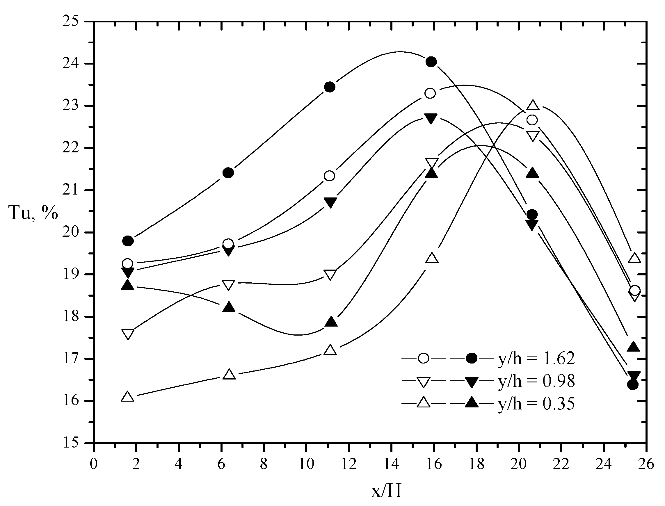
Figure 5.
Maximum velocity of the reverse flow in the recirculation region.
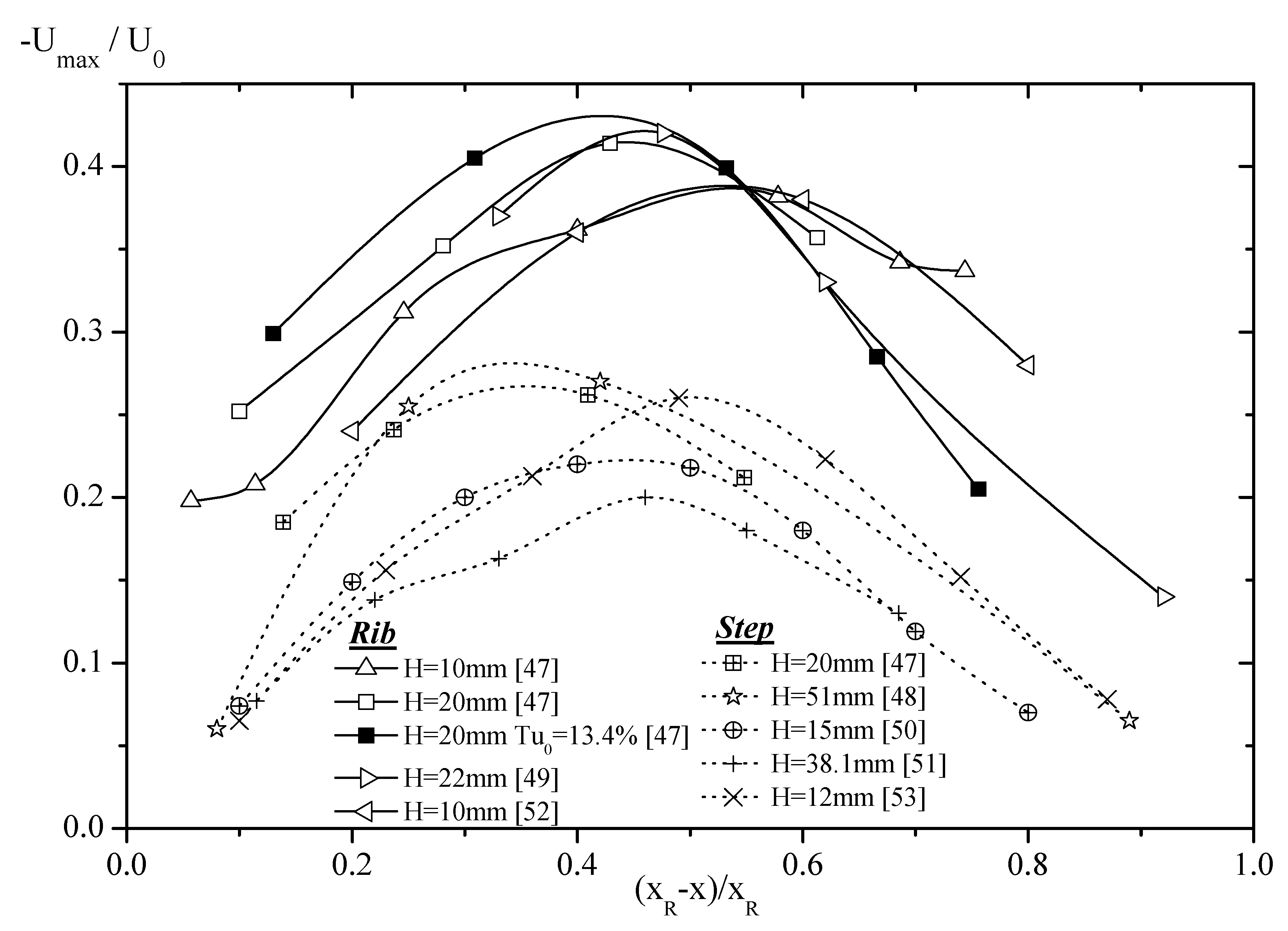
Figure 6.
Maximum turbulence intensity distribution behind a rib and a step. Rib: H = 6 mm (Tu0 = 13.4%); step: H = 20 mm (open symbols—Tu0 = 1.2%, closed ones—Tu0 = 13.4%).
Figure 6.
Maximum turbulence intensity distribution behind a rib and a step. Rib: H = 6 mm (Tu0 = 13.4%); step: H = 20 mm (open symbols—Tu0 = 1.2%, closed ones—Tu0 = 13.4%).
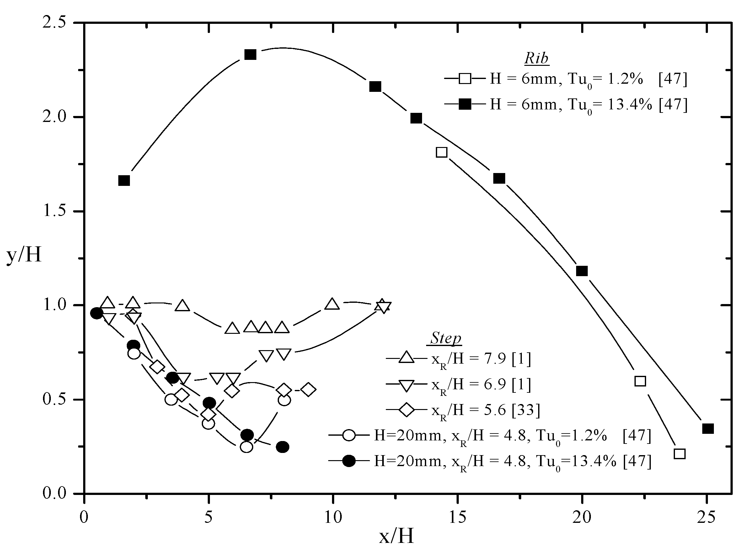
Figure 7.
Pressure coefficients distribution behind a rib (a) and a step (b) [47].
Figure 7.
Pressure coefficients distribution behind a rib (a) and a step (b) [47].
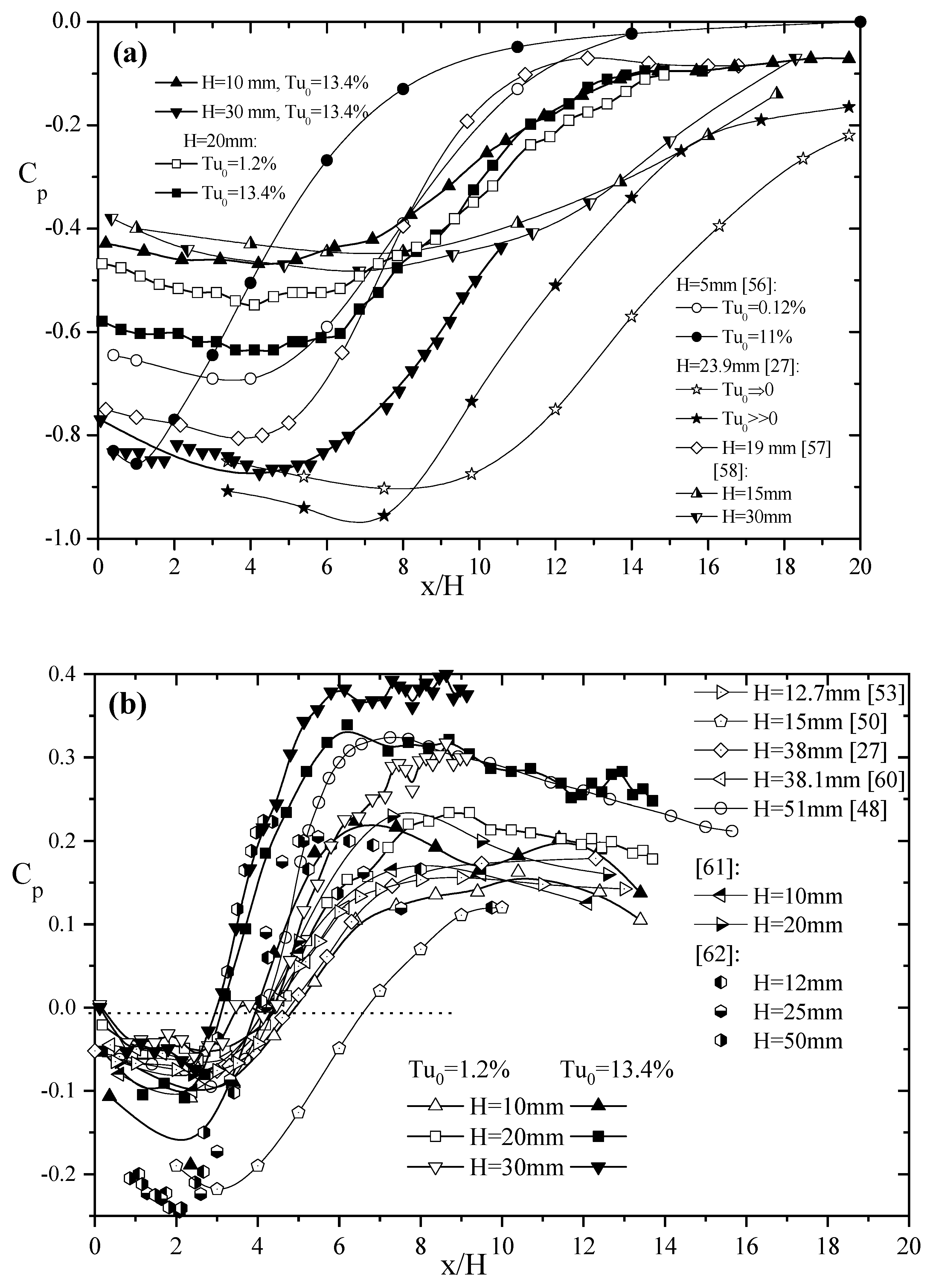
Figure 8.
Generalization of experimental data on the pressure coefficient behind the rib in universal coordinates.
Figure 8.
Generalization of experimental data on the pressure coefficient behind the rib in universal coordinates.
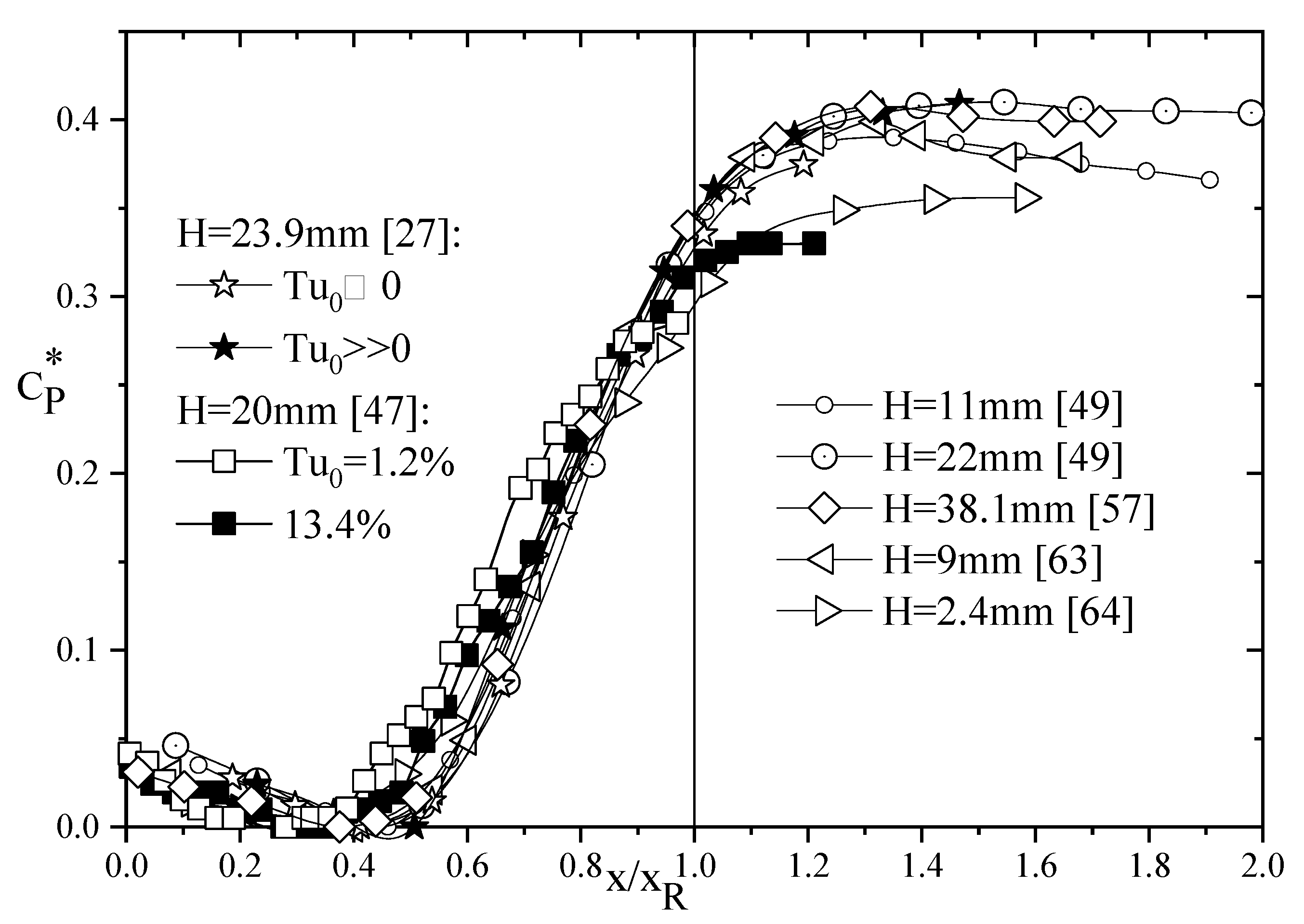
Figure 9.
Temperature profiles behind the rib (a) and step (b) (H = 20 mm). Behind the step: open points—Tu0 = 1.2%, dark points—Tu0 = 13.4%.
Figure 9.
Temperature profiles behind the rib (a) and step (b) (H = 20 mm). Behind the step: open points—Tu0 = 1.2%, dark points—Tu0 = 13.4%.
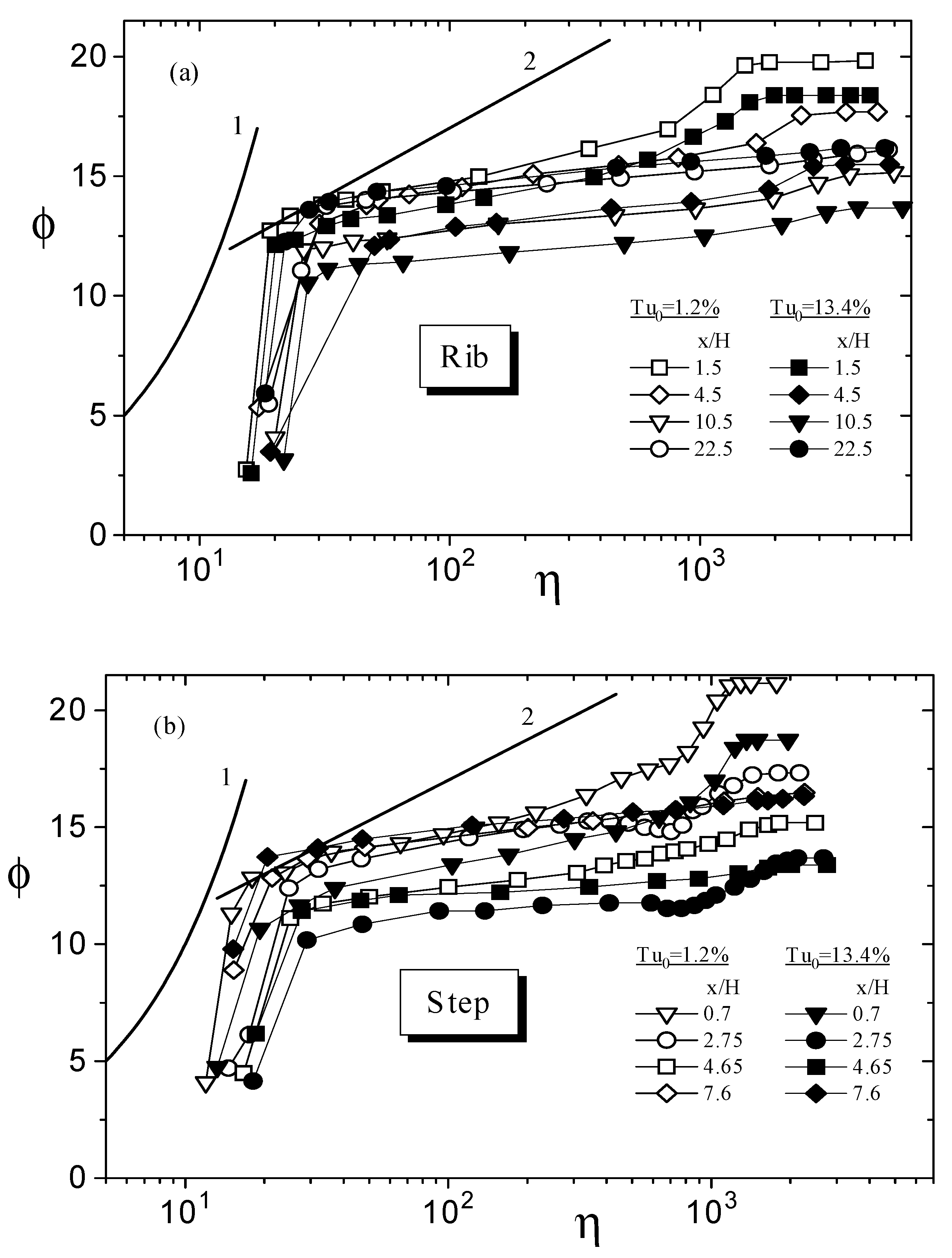
Figure 10.
Distribution of the Nusselt number behind the step (a) and rib (b). (H = 20 mm). 1—Tu0 = 1.2%; 2—5%; 3—13.4% [26].
Figure 10.
Distribution of the Nusselt number behind the step (a) and rib (b). (H = 20 mm). 1—Tu0 = 1.2%; 2—5%; 3—13.4% [26].
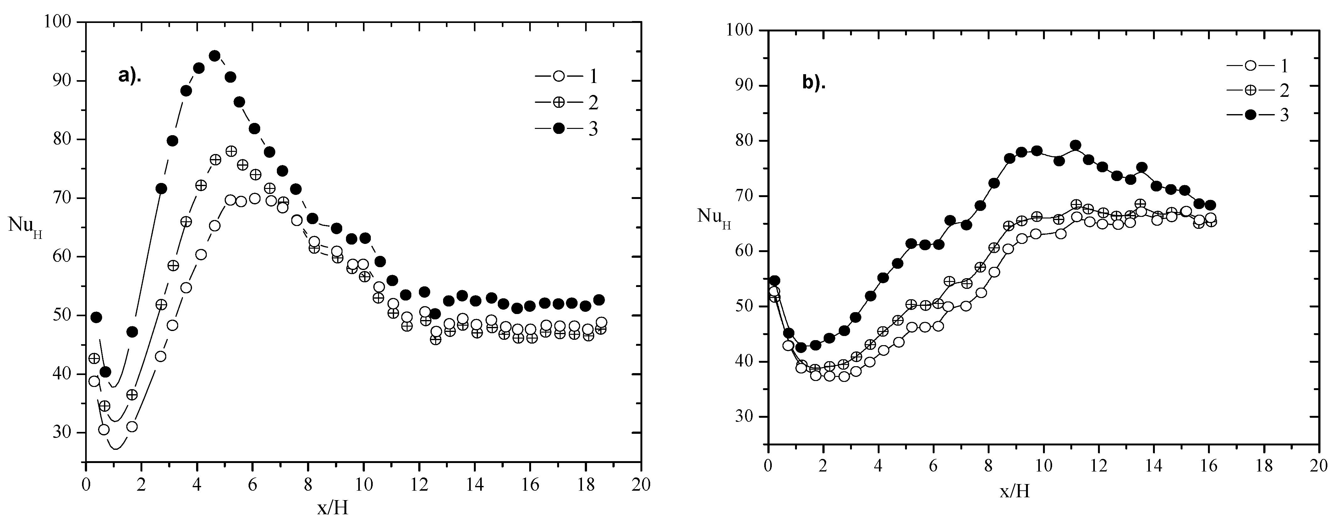
Figure 11.
Influence of the degree of turbulence on the effect of heat transfer intensification for the backward-facing step (a) and rib (b) [26].
Figure 11.
Influence of the degree of turbulence on the effect of heat transfer intensification for the backward-facing step (a) and rib (b) [26].

Figure 12.
The law of heat transfer in the separation zone behind the step for the maximum Nusselt number. L is the distance along the dividing line. Line 1—[66], 2—[67].
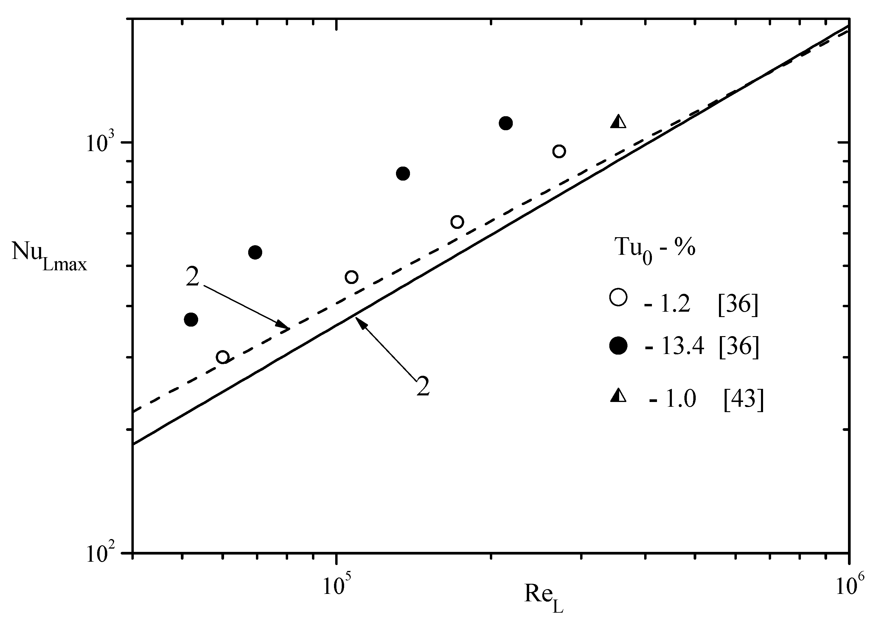
Figure 13.
The scheme of the flow behind the backward-facing inclined step (a) and maximum heat transfer coefficient at different angles of inclination with variations in the level of turbulence (b). [26,43].
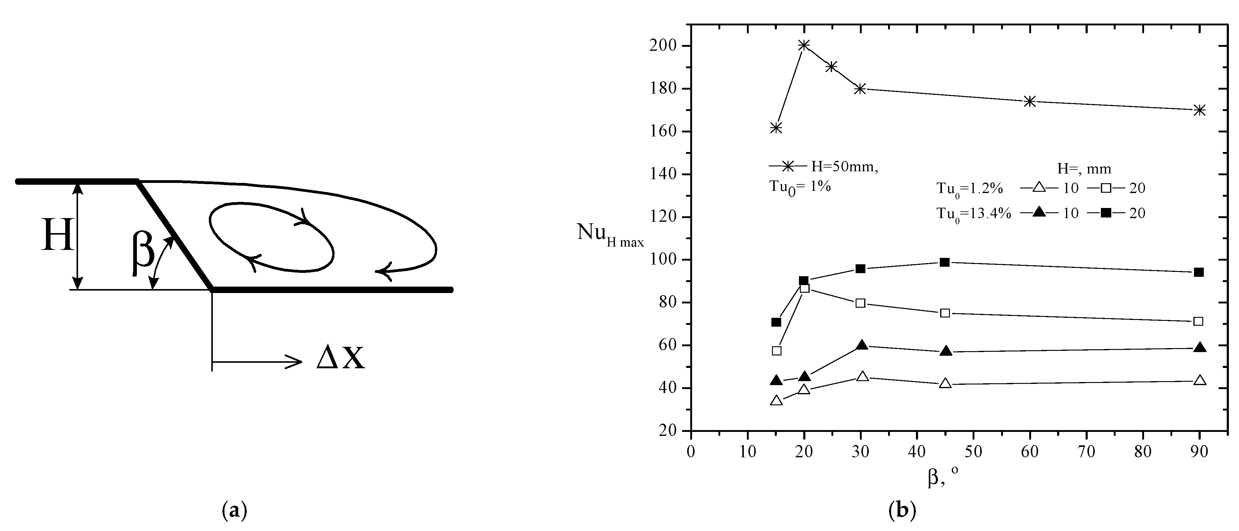
Figure 14.
Set-up with an inclined rib. 1—rib, 2—streamline. All dimensions are in mm.

Figure 15.
Longitudinal distribution of pressure coefficient behind the rib at ϕ = 60 and 90° in five sections along the channel width (z is indicated in mm).
Figure 15.
Longitudinal distribution of pressure coefficient behind the rib at ϕ = 60 and 90° in five sections along the channel width (z is indicated in mm).
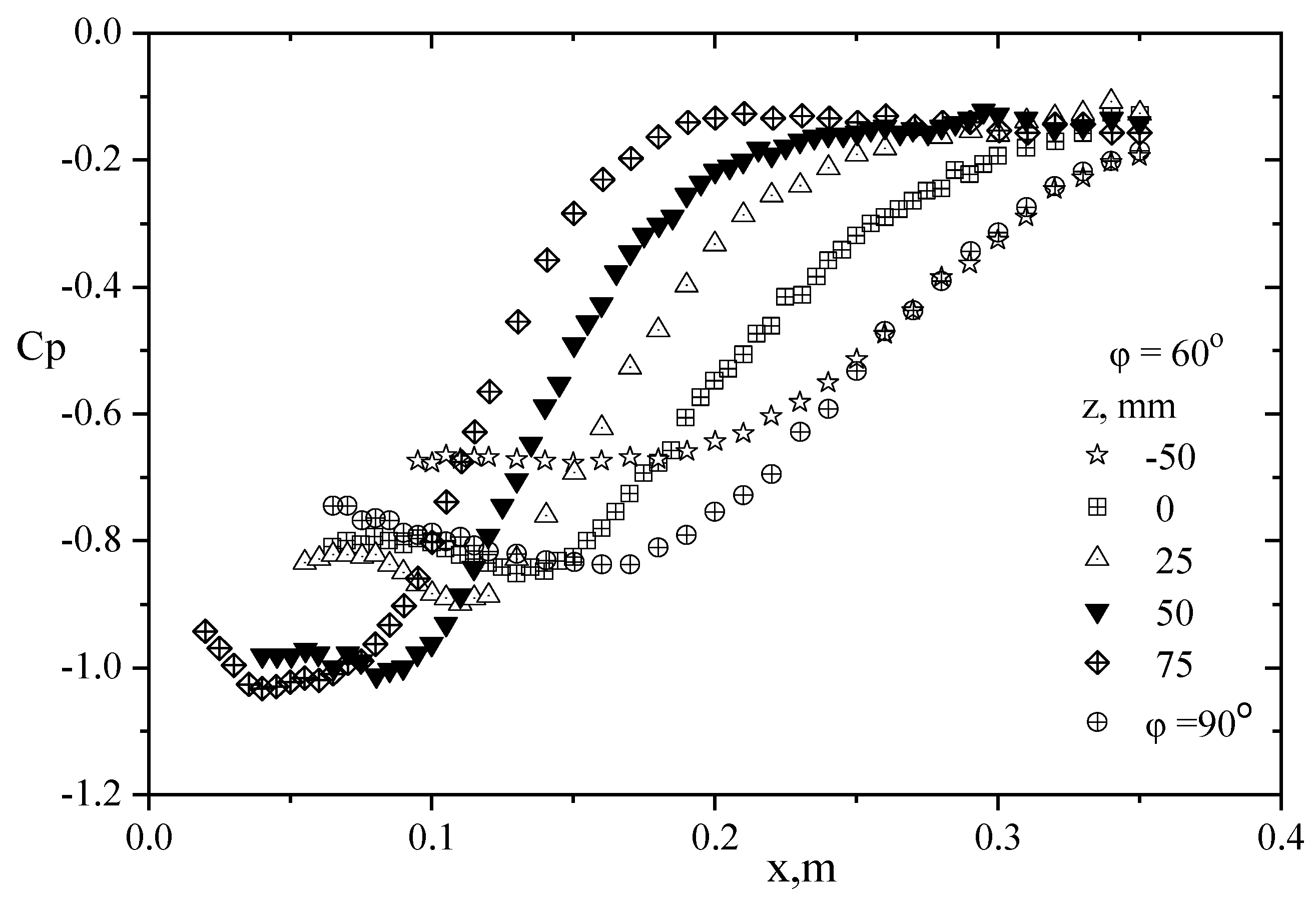
Figure 16.
Influence of high turbulence of the external flow on heat transfer behind a single rib at different angles of inclination to the main flow. (a)—rib H = 20 mm, 1—ϕ = 50°; 2—ϕ = 60°; 3—ϕ = 70°; 4—ϕ = 80°. (b)—rib ϕ = 60°, 1—H = 20 mm; Tu0~1.2%; 2—H = 20 mm, Tu0~13.4%; 3—H = 6 mm, Tu0~1.2%; 4—H = 6 mm; Tu0~13.4% [40,65].

Figure 17.
The geometric dimensions of the cavity: H—depth, L—width, LW—sidewall length, ϕ—angle of side wall inclination.
Figure 17.
The geometric dimensions of the cavity: H—depth, L—width, LW—sidewall length, ϕ—angle of side wall inclination.
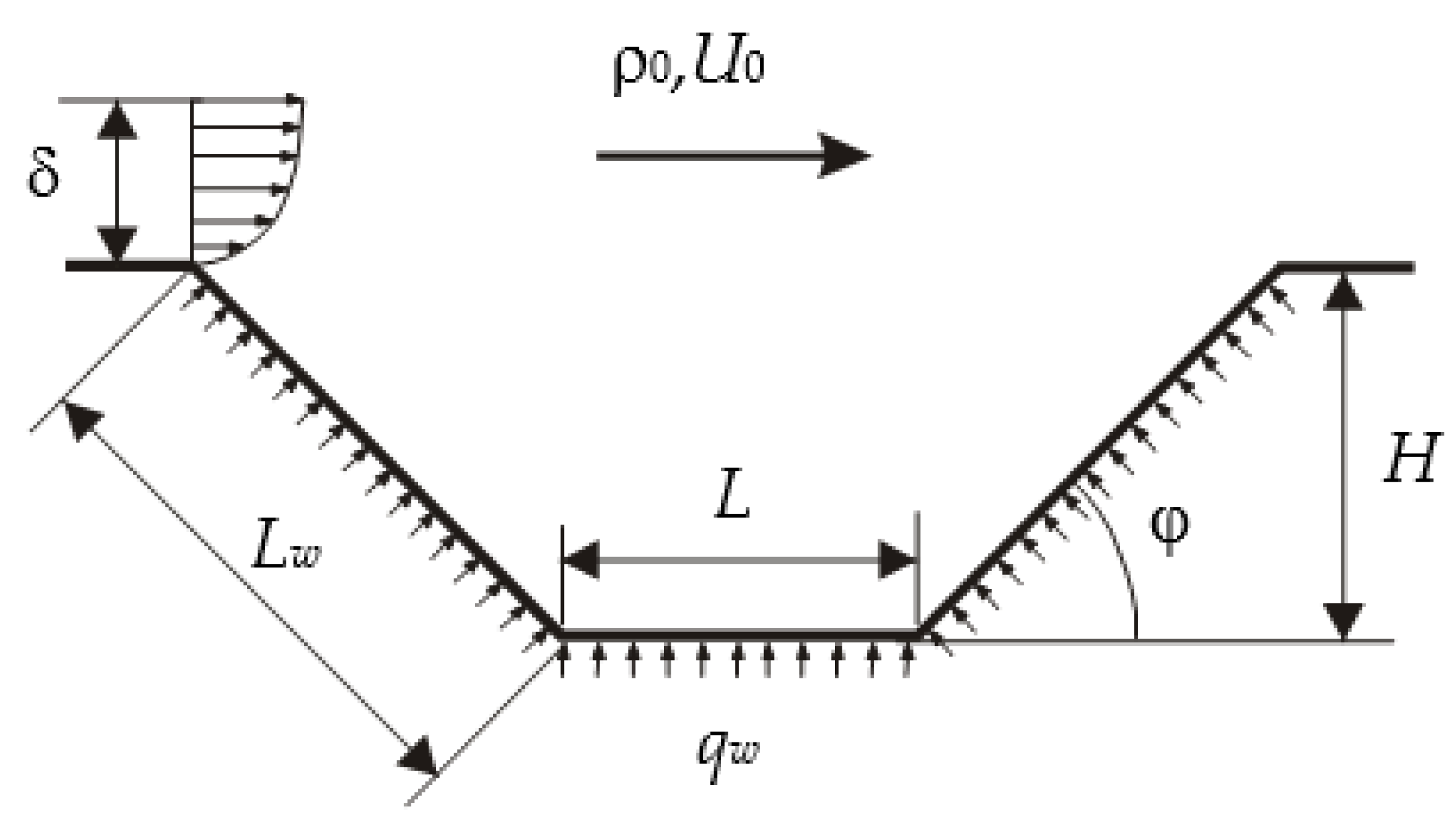
Figure 18.
Pressure distribution in the midsection along the walls of the cavity with different angles of side wall inclination.
Figure 18.
Pressure distribution in the midsection along the walls of the cavity with different angles of side wall inclination.
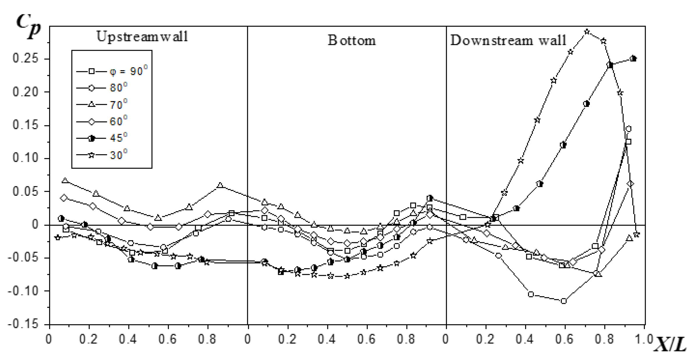
Figure 19.
Distribution of local heat transfer coefficients in the midsection of the cavity at different degrees of turbulence intensity. ϕ = 45°. 1—Tu = 1.2%; 2—6.5%; 3—15.8%.
Figure 19.
Distribution of local heat transfer coefficients in the midsection of the cavity at different degrees of turbulence intensity. ϕ = 45°. 1—Tu = 1.2%; 2—6.5%; 3—15.8%.
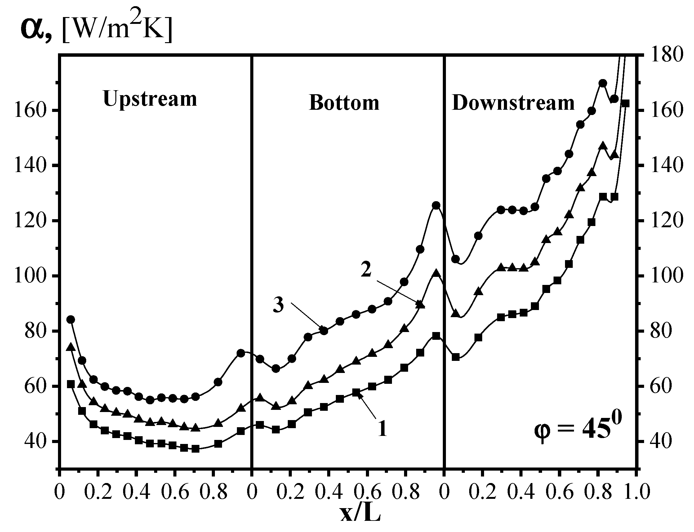
Figure 20.
The effect of heat transfer intensification during high-turbulent flow in trenches.
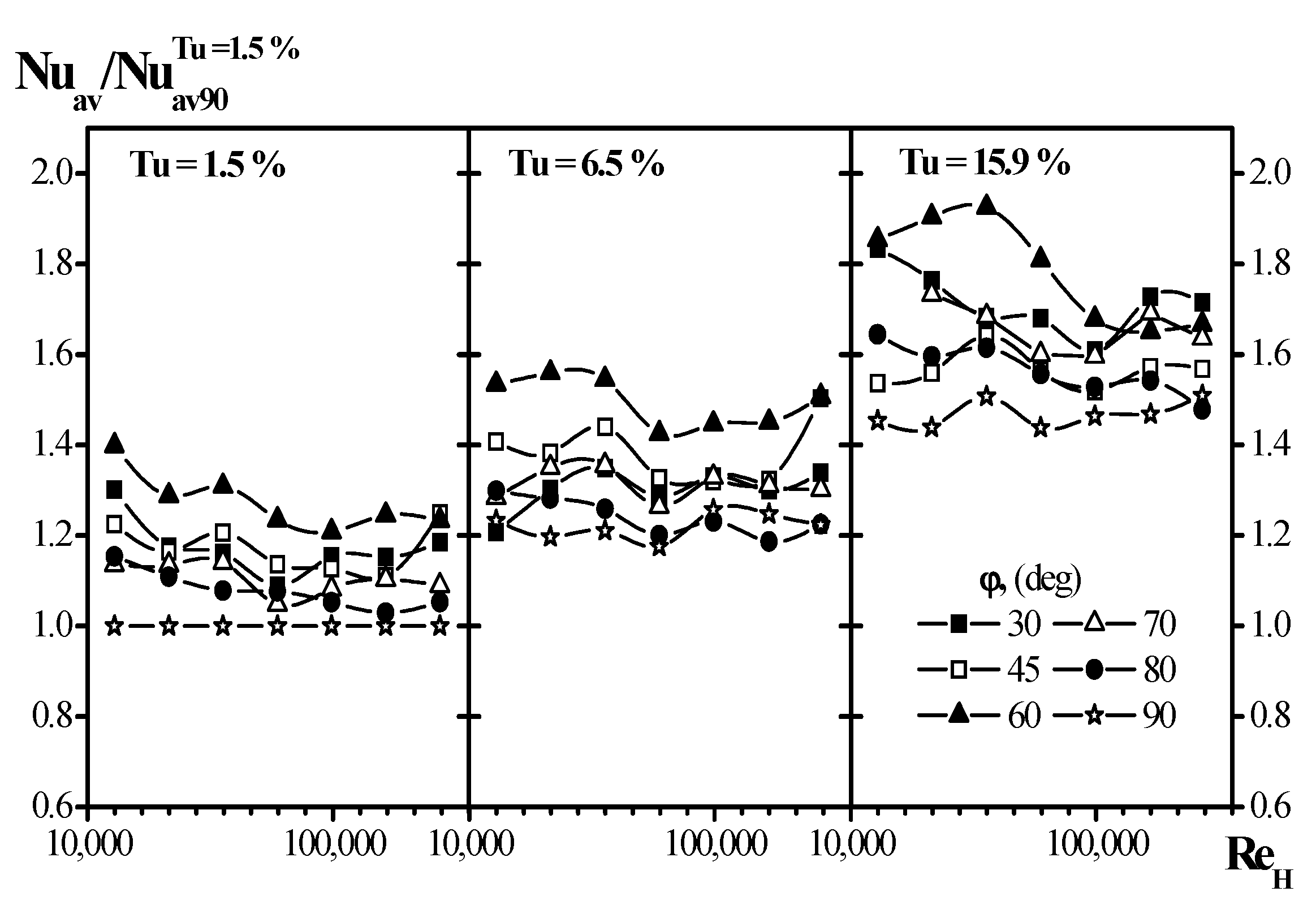
Figure 21.
Flow diagram with a system of straight ribs.
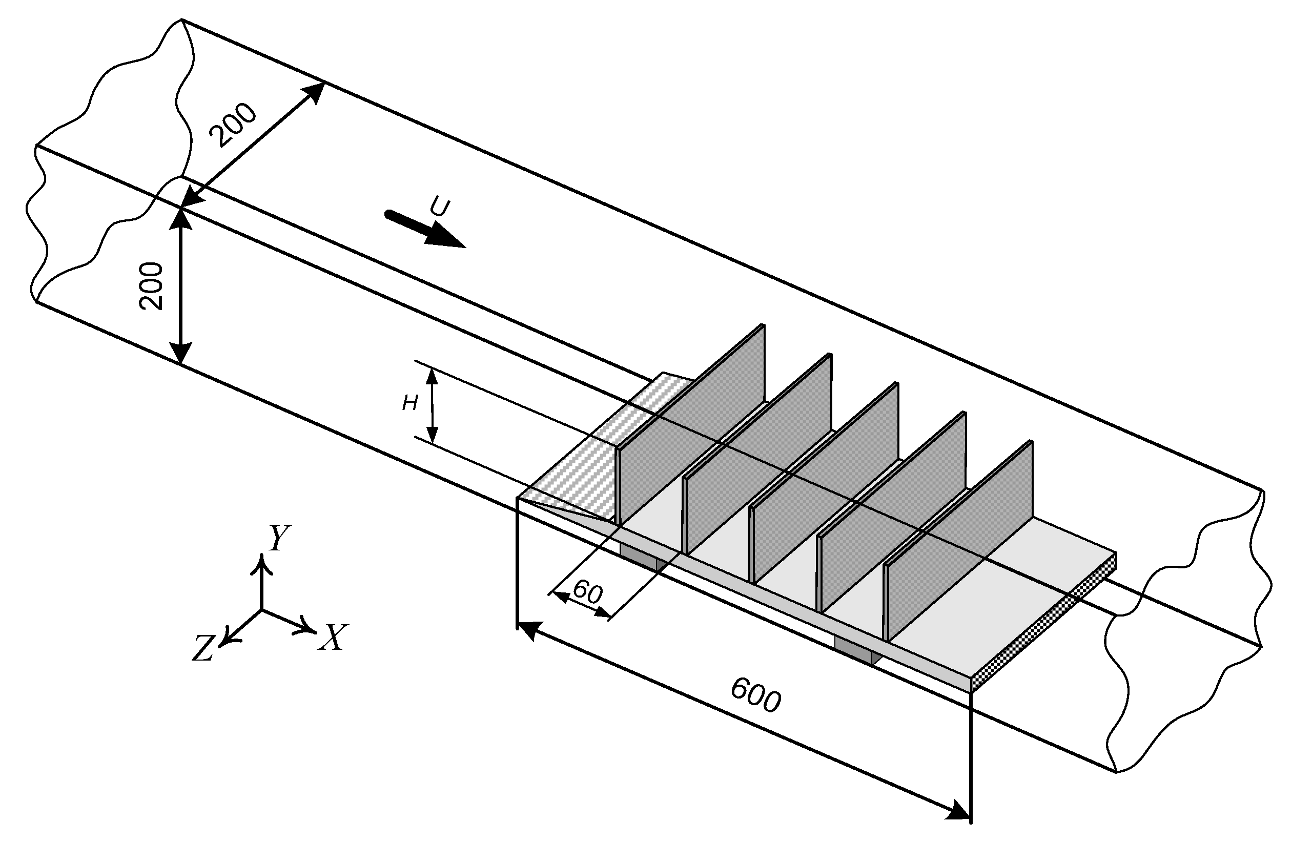
Figure 22.
Pressure distribution on the surface with a different number of ribs. (a)—Tu = 1.5%, (b)—15%.
Figure 22.
Pressure distribution on the surface with a different number of ribs. (a)—Tu = 1.5%, (b)—15%.
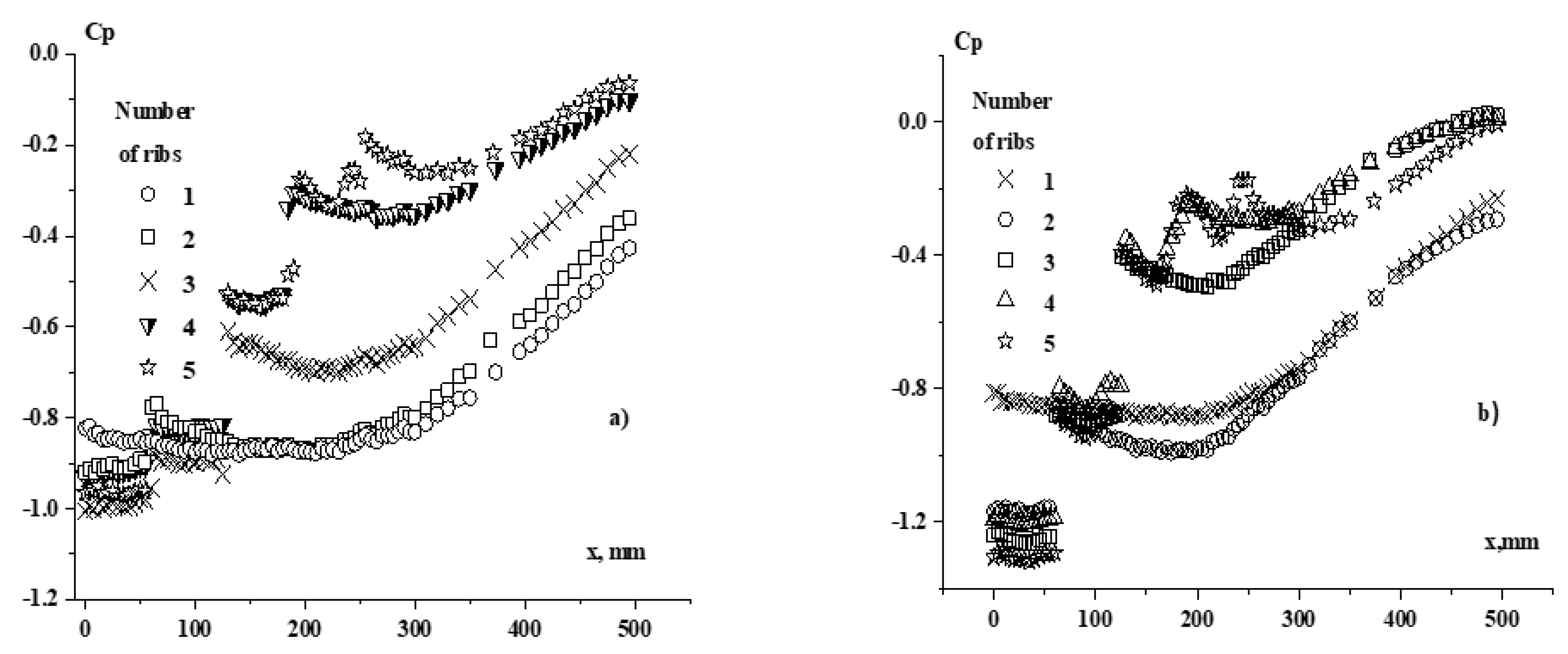
Figure 23.
Distribution of the coefficient averaged heat transfer coefficient over the cell surface when flowing around from two to five fins (light symbols—Tu0 = 1.5%; dark ones—Tu0 = 15%) [40].
Figure 23.
Distribution of the coefficient averaged heat transfer coefficient over the cell surface when flowing around from two to five fins (light symbols—Tu0 = 1.5%; dark ones—Tu0 = 15%) [40].

Publisher’s Note: MDPI stays neutral with regard to jurisdictional claims in published maps and institutional affiliations. |
© 2021 by the author. Licensee MDPI, Basel, Switzerland. This article is an open access article distributed under the terms and conditions of the Creative Commons Attribution (CC BY) license (http://creativecommons.org/licenses/by/4.0/).
Share and Cite
MDPI and ACS Style
Terekhov, V.I. Heat Transfer in Highly Turbulent Separated Flows: A Review. Energies 2021, 14, 1005. https://doi.org/10.3390/en14041005
AMA Style
Terekhov VI. Heat Transfer in Highly Turbulent Separated Flows: A Review. Energies. 2021; 14(4):1005. https://doi.org/10.3390/en14041005
Chicago/Turabian StyleTerekhov, Viktor I. 2021. "Heat Transfer in Highly Turbulent Separated Flows: A Review" Energies 14, no. 4: 1005. https://doi.org/10.3390/en14041005
Note that from the first issue of 2016, this journal uses article numbers instead of page numbers. See further details here.