
Analysis and Design of a Multi-Port DC-DC Converter for Interfacing PV Systems


1
Electrical Engineering Technology Department, College of Technological Studies, Doha 35001, Kuwait
2
Electrical Power and Machines Department, Faculty of Engineering, Ain Shams University, Cairo 11769, Egypt
3
Electrical and Control Department, College of Engineering & Technology, Arab Academy for Science, Technology & Maritime Transport, Cairo 2033, Egypt
*
Author to whom correspondence should be addressed.
Energies 2021, 14(7), 1943; https://doi.org/10.3390/en14071943
Submission received: 22 February 2021
/
Revised: 24 March 2021
/
Accepted: 26 March 2021
/
Published: 1 April 2021
(This article belongs to the Special Issue Power Conversion and Control in Photovoltaic Power)
Abstract
:A high-frequency multi-port (HFMP) direct current (DC) to DC converter is presented. The proposed HFMP is utilized to interface a photovoltaic (PV) system. The presented HFMP is compact and can perform maximum power point tracking. It consists of a high-frequency transformer with many identical input windings and one output winding. Each input winding is connected to a PV module through an H-bridge inverter, and the maximum PV power is tracked using the perturb and observe (P&O) technique. The output winding is connected to a DC bus through a rectifier. The detailed analysis and operation of the proposed HFMP DC-DC converter are presented. Extensive numerical simulations are conducted, using power system computer aided design (PSCAD)/electromagnetic transients including DC (EMTDC) software, to evaluate the operation and dynamic behavior of the proposed PV interfacing scheme. In addition, an experimental setup is built to verify the performance of the HFMP DC-DC converter.
1. Introduction
Recently, photovoltaics (PV) interfacing systems have been attracting widespread attention. Many schemes are used for PV interfacing systems [1,2,3,4,5]. A classical PV interface scheme is formed from three stages. In the first stage, a direct current (DC)-DC converter performs a maximum power point track (MPPT) of the PV array. An inverter, usually of the voltage-source type, is used in the second stage followed by a step-up transformer in the third stage to connect with the grid. The power transformer used in this interface scheme leads to many drawbacks, such as a reduced conversion efficiency and an increased cost and size. One advantage of this scheme is the capability to connect many converters to the DC side of the inverter to interface separate PV modules [6,7]. Besides the increased reliability of this multi-port (MP) scheme, it can track the maximum power points (MPPs) of different PV modules regardless of the shading conditions. There is also a reduced PV interface scheme where the DC-DC converter is eliminated, and the inverter is controlled to achieve MPPT [8,9].
Many PV interfacing systems that utilize high-frequency transformers (HFTs) have been introduced to avoid the aforementioned drawbacks of the classical scheme. The high-frequency DC (HFDC) link is used to raise the photovoltaic voltage for the connected voltage source inverter [10]. The MPPT can be achieved by adjusting the pulse width of the high-frequency H-bridge converter of the HFDC or by regulating inverter output current [11]. The dual active bridge used in PV systems, such as MPPT, is achieved by adjusting the phase shift angle [12,13]. The high-frequency alternative current (HFAC) link converter is used in the PV interface system to remove the large-sized DC-link capacitor [14,15]. In spite of the reduced size of the HFAC link converter compared to the HFDC, more switches and a complex control system are required. The cascaded high-frequency link (CHFL) has been used in a medium voltage connection [16,17,18]. The CHFL systems are based on an HFT of multiple secondary windings that are associated with either AC/DC/AC converter cells [17] or AC/AC converter cells [18]. The cells are cascaded and connected to reach the medium voltage level. The primary winding is connected to PV arrays through a low-voltage high-frequency H-bridge converter. Despite the advantages of the CHFL systems, they have a single input port for transfer of the harvested power from the PV arrays. However, complex MPPT techniques are required for the CHFL system to work effectively under partial shading.
The MP PV interface systems are realized by connecting each PV module to the DC-link through a separate DC-DC converter, which is costly and bulky [19]. To reduce the cost and size of MP converters, a topology, based on buck converters, to accommodate many input sources using a single inductor is used [20]. However, this MP converter topology is not isolated and requires a complex controller to generate gating signals for the different input ports, which complicate the PV system requirements. The proposed MP converter presented in Reference [21] consists of a center-taped transformer with multiple windings and three-leg converters connected to each port. In addition, a large number of components is needed. In the literature, phase-shift control is applied to control power flow between multiple active bridges coupled on HFT [22,23,24,25]. In this technique, external inductors are used for each port to allow for proper range of angle control. In addition, a complex control scheme is regulated to eliminate the circulating currents between ports [26].
This paper introduces a high-frequency multi-port (HFMP) DC-DC converter to interfacing PV systems. The HFMP system is formed from many H-bridge converters connected to identical windings placed on the same core with one output winding that is connected to a DC bus through a rectifier. The duty cycle of each H-bridge is adjusted to perform MPPT for the associated PV module at different irradiance levels. This will allow using the conventional perturb and observe (P&O), presented in References [27,28], to harvest the maximum power from the PV, and also the partial shading will have minimum impact on the system. One of the main advantages of the proposed PV interfacing scheme compared to the phase-shift controlled multiple active bridges is the elimination of an external inductor needed for power flow control. In addition, the output port is a passive rectifier. As a result, the cost and size of the proposed PV interface system is reduced. The experimental prototype of the proposed system is based on three HFT windings with a toroidal core. The two input windings have 10 turns, while the output winding has 20 turns. The detailed design of the high-frequency transformer can be found in Appendix A. The main difference between the MP converter presented in this paper and that in Reference [29] is the topology of the converters used for the input ports. In this paper, classical H-bridges are used for input ports which allow for bidirectional power flow between ports, a feature needed to integrate storage elements like batteries, unlike the topology presented in Reference [29], which allows only for unidirectional power flow from input ports to the output port.
The paper is structured as follows: the HFMP converter is described in Section 2. The operating modes and the theoretical analysis of the proposed HFMP converter are presented in Section 3. Simulation results are discussed in Section 4. Section 5 details the experimental verification of the proposed system. Finally, Section 6 presents the conclusion.
2. The Proposed HFMP DC-DC Converter
Figure 1 presents the proposed HFMP DC-DC converter. It is based on an HFT with many input windings. Figure 1a shows a converter with three input windings and one output winding. Each input winding is connected to a PV module through a quasi-square pulse H-bridge inverter. The output winding is connected to a DC bus through a rectifier with a capacitor filter. The ratio of the turn between the input and output windings is 1:1:1:N. The ratio of the turn N is selected based on the DC bus voltage level VB. The gating signals for the H-bridges of the proposed HFMP converter are shown in Figure 1b. For the H-bridge of unit ‘x’, one-leg switches (S3x and S4x) operate at a 50% duty cycle and (S1x and S2x) are controlled by adjusting a duty cycle of Dx. As a result, only one switch is turned on during the zero-voltage state. This action prevents the short-circuiting of other H-bridge converters working at positive or negative voltage states. Practically, circulating current may flow only if the voltage difference between any two PV modules exceeds the forward voltage drop of two switches and two body diodes. Therefore, the proposed topology is suitable for interfacing PV modules of the same type as the operating voltage range for MPP at different irradiance levels is narrow and cannot excite circulating current between H-bridge inverters, as will be shown in the results.
Each H-bridge has its own independent MPPT controller. This action enables the proposed topology to extract the maximum PV power without the need for complex MPPT techniques used for partial shading conditions. In addition, the proposed PV interfacing system is modular as extra units can be integrated by adding windings with proper turns to the core of the HFT to increase their maximum extracted power. Based on PV voltage and current, the P&O adjusts the duty cycle Dx of unit ‘x’ to perform MPPT, as shown in Table 1 [30,31].
3. Principles of Operation
This section presents the analysis and operation principles of the proposed HFMP DC-DC converter. For simplicity, a two-input unit topology will be discussed, which has five modes of operation for each half cycle, as shown in Figure 2. These modes are determined by the switching states of the two H-bridges. Figure 3 shows the HFT terminal voltages and currents during different operating modes. Neglecting the resistances of the windings and considering identical input windings of the HFT, L1a = L1b = L1, the system can be modelled as follows:
where v1x and i1x are the voltage and current respectively, of the input winding connected to unit ‘x’, v2 and i2 are the voltage and current of the output winding respectively, L1 and L2 are the leakage inductances of the input and output windings respectively, and E is the HFT-induced voltage at any of the input windings. In this analysis, the capacitor voltage ripple is not considered and hence vC ≈ vB. The following subsections present the analysis of each mode.
3.1. Mode 1: t0–t1
This mode is initiated at the beginning of the switching cycle t0 when both H-bridge converters are switched to their positive voltage state, S1a = S4a = S1b = S4b = 1. This mode lasts until one of the H-bridges is switched to a zero state. In this analysis, the duty cycle of unit ‘a’ is supposed to be greater than that of unit ‘b’, Da > Db. Therefore, S1b is turned off earlier than S1a at t1, as indicated in Figure 3. During this mode, both units sending power to the output winding, the currents in the windings rise, as indicated in Figure 3. Using Figure 2a and considering that the switches are ideal (zero voltage drop) and solving (1) to (3) to find the currents of units ‘a’ and ‘b’ at the instant t = t1 as follows:
where f = 1/T refers to switching frequency, and va and vb are the PV voltages of unit ‘a’ and unit ‘b’ voltage.
3.2. Mode 2: t1–t2
At t1, the H-bridge converter with the low duty cycle, unit ‘b’, is switched to a zero-voltage state, S1b = 0. Accordingly, v1b falls to zero and the stored energy in the winding inductance L1b is discharged through S4b and D2b, as illustrated in Figure 2b, until the end of mode 2 at t2, where i1b decays to zero, as indicated in Figure 3. Consequently, the transformer-induced electromagnetic force (EMF) reduces during the time interval of this mode, λ. Therefore, the current of unit ‘a’, which is feeding power to the At t1, the H-bridge converter with the low duty cycle, unit ‘b’, is switched to a zero-voltage state, S1b = 0. Accordingly, v1b falls to zero and the stored energy in the winding inductance L1b is discharged through S4b and D2b, as illustrated in Figure 2b, until the end of mode 2 at t2, where i1b decays to zero, as indicated in Figure 3. Consequently, the transformer-induced EMF reduces during the time interval of this mode, λ. Therefore, the current of unit ‘a’, which is feeding power to the output side, increases according to (1). In addition, i2 decreases. The downslope rate of i1b is proportional to the DC bus voltage vB. Solving (1) to (3) by substituting v1b = 0 and using Ia1 and Ib as initial values for the winding currents, results in the following expressions:
where Ia2 is the current of unit ‘a’ at the end of this mode, t2. It is worth mentioning that due to the low HFT inductance, this interval time is too short.
3.3. Mode 3: t2–t3
At t2, the winding terminals of unit ‘b’ become floating, as denoted in Figure 2c; i1b = 0, and its voltage is E, which is a slightly lower than va because of the leakage inductance of unit ‘a’ voltage drop. This mode ends at t3 when S1a is turned off, as illustrated in Figure 3. The slope of i1a should be very close to that of mode 1. According to (3), the slope of the output winding current i2 is lower than its rate during mode 1 as the power is supplied from one unit only. The maximum current of unit ‘a’ Ia3 is expressed in (8) by solving (1) to (3) and using Ia2 as the initial value.
3.4. Mode 4: t3–t4
This mode starts at t3 where v1a falls to zero. As seen in Figure 2d, the stored energy in the inductances of the windings L1a and L2 is discharged through S4a, D2a, and a rectifier to the load side, as illustrated in Figure 3. Therefore, the voltage across the output winding terminals remains equal to vC during the time interval of this mode δ. In addition, the transformer-induced EMF and unit ‘b’ voltage reduce as shown in (9):
Mode 4 duration can be calculated by solving Equations (1) to (3) as follows:
3.5. Mode 5: t4–t5
At t4, the currents in the windings are discharged to zero, and the HFT becomes de-energized, as indicated in Figure 2d. This mode is terminated at the beginning of the negative half-cycle t5, as indicated in Figure 3. Similar to the positive half-cycle, the negative half-cycle has five modes of operation. It is worth mentioning that the 50% fixed duty cycle gated switches (S3x and S4x) attain zero-current switching (ZCS) when turned off. In addition, ZCS is achieved due to the discontinuous conduction mode (DCM) of operation.
The total output power is the sum of the power delivered from each unit, as follows:
where P, Pa, and Pb are the power at the output side, the power at unit ‘a’, and the power at unit ‘b’, respectively. Equations (12) and (13) indicated that the power transfer from each unit can be controlled by adjusting the duty cycles. This analysis can be extended to an HFMP DC-DC converter with similar χ input windings, where each added winding introduces modes the same as modes 2 and 3. Thus, the number of modes of operations per half-cycle cannot exceed 2χ + 1 for the proposed system, with χ units working at different duty cycles.
4. Simulation Results
Power system computer aided design (PSCAD)/electromagnetic transients including DC (EMTDC) software is used to simulate the proposed HFMP converter. The system parameters for the simulation and experimental work are given in Table 2. The proposed system performance is investigated by two different case studies. Firstly, the different operating modes of the proposed HFMP converter are demonstrated. Secondly, the dynamic performance of the proposed HFMP converter is evaluated under different irradiance levels and during the partial shading condition.
4.1. The Proposed Converter with Two Input Units Fed from DC Supplies
In this case study, two input units are fed from two identical DC supplies, va = vb = 50 V. The duty cycles for the H-bridge converters of units ‘a’ and ‘b’ are set at 70% and 35%, respectively. The voltages and currents of different windings are displayed in Figure 4a,b, respectively. The five operating modes per half-cycle, discussed in Section 3, are shown. Since the two units have the same supply voltage, their currents are identical during mode 1. In addition, their maximum current at the end of mode 1 is 4 A, consistent with (4) and (5). The time initial values of mode 2 and mode 4 are 0.9 and 3.8 μs, and these values are similar to their analytical results obtained from (6) and (10), respectively. Figure 4c indicates that the input unit currents ia and ib follow the rectified waveforms of their winding currents i1a and i1b respectively, excluding the discharging intervals. During mode 2, the H-bridge converter of unit ‘b’ is now operating at zero state, v1b = 0, and its winding current is discharged through S4b and D2b. Therefore, the current of unit ‘b’ ib is interrupted immediately at the beginning of mode 2, and the power delivery from unit ‘b’ to the output side is terminated. Similarly, at the beginning of mode 4 when v1a = 0, the supply of unit ‘a’ is disconnected from its winding, ia = 0, and the power transfer is ended. In addition, the voltage across the floating winding of unit ‘b’ during mode 4 is 22.7 V, which is close to the estimated value from (9). The maximum values of the current of unit ‘a’ during modes 2 and 3 are Ia2 = 6.5 A and Ia3 = 12.3 A, respectively. These parameters are consistent with the theoretical values obtained from (7) and (8).
4.2. The Proposed Converter with Three Input Windings Fed from PV Modules
In this section, the dynamic performance of the proposed HFMP converter is tested under different irradiance levels. Three PV modules are considered, where each PV unit is tied to a port of the proposed HFMP converter. The PV module specifications are listed in Table 3. Figure 5 shows PV module characteristics at different irradiance levels.
The PV voltage at the MPP varies from 54 to 51 V when the irradiance level is changed from 1000 to 250 W/m2, respectively. Therefore, the maximum voltage difference between the units does not exceed 3 V, which is lower than the voltage drops across four switching elements of the H-bridge inverters. As a result, no circulating currents flow between different H-bridge inverters, as discussed in Section 2.
The irradiance levels for the three PV units, ‘a’, ‘b’, and ‘c’, are indicated in Figure 6a. The irradiance level at the PV of unit a is assumed constant at 1000 W/m2. The irradiance levels for the other two PV modules are hypothetically changed. The extracted power from the PV module units Pa, Pb, and Pc, are illustrated in Figure 6b. It can be observed that the proposed HFMP converter succeeded to track the PV module maximum power in a smooth manner. For each H-bridge converter, the duty cycle is obtained from its MPPT unit, as demonstrated in Figure 1. Figure 6c exhibits the duty cycles for the three units, Da, Db, and Dc.
The voltages and currents of the PV modules are portrayed in Figure 7a,b, respectively. The P&O MPPT regulates duty cycle, for each unit, to track the maximum power from each PV module. As the DC bus voltage is kept constant, the duty cycle of each unit is proportional to the corresponding PV module voltage at the MPPT. The extracted power and PV current are varying with irradiance level. Since unit ‘a’ is exposed to constant irradiance, its duty cycle Da remains constant to keep the operation at the MPP irrespective to the irradiance levels of the other units. Figure 7c shows the delivered power to the dc-bus, which is the sum of the power sent from each unit. The simulation results show that the proposed HFMP converter has a good dynamic performance and succeeds to perform MPPT with minimum transients.
Figure 8 traces the voltages and currents of each unit of the HFMP converter where the irradiance level of units ‘a’, ’b’, and ’c’ are 1000, 750, and 500 w/m2, respectively. As a result, the three PV units operate at different voltages to harvest the MPP from each module. During mode 1, the currents increase at different slopes, as in Figure 8c. The current of unit ‘a’ increases faster than the other units since it faces the highest irradiance level.
As discussed in Section 3, there are seven operating modes in each half-cycle for the three-input winding topology of the proposed converter, where modes 2 and 3 are duplicated. Mode 2 is shown in Figure 8a when the voltage of unit ‘c’ is turned to zero and i1c is dropped, as indicated in Figure 8c. Consequently, mode 3 will start once i1c becomes zero, and its voltage v1c will be equal to the transformer EMF. Similar to modes 2 and 3, modes 4 and 5 refer to the intervals when the winding of unit ‘b’ is switched to a zero state and is floating, respectively. Mode 6 is shown in Figure 8a,c, which depict when v1a is switched to zero and i1a is discharging, respectively. When the voltages and currents of all windings become zero, mode 7 begins.
5. Experimental Results
A prototype for the proposed HFMP converter has been implemented for validation, as shown in Figure 9. The prototype consists of an HFT with two input units. Each unit is formed from an H-bridge converter connected to a programmable power supply (PPS), EA-PS-83600-10 with analogue interface, to emulate the PV characteristics of Figure 5 at different irradiance levels. The output winding of the HFT is connected to a fixed DC bus through a rectifier. The parameters of the system are listed in Table 3. The power MOSFETs used for H-bridges are IXFQ20N50P3, and the fast diodes of the rectifier are MUR2020R. In the PV emulator, for every irradiance level set point, the programmable system-on-chip (PSoC) digital controller (CY8C5888LTI-LP097) calls the built-in PV model program to send the reference maximum output power and current to PPS, and based on the PV emulator average output current, the PSoC digital controller sets the PPS reference voltage.
The design details of the output filter components and the high-frequency transformer are given in Appendix A and Appendix B, respectively. The P&O techniques for the two units are implemented using the programmable system-on-chip (PSoC) digital controller, which generates the gating signals for the switches.
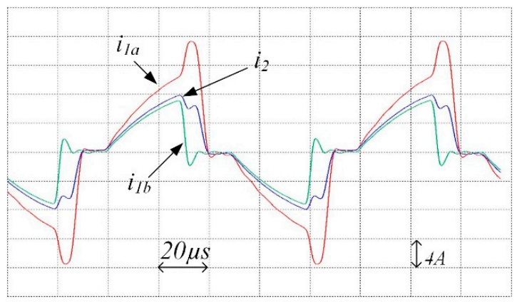
Three experimental case studies were conducted. The first case study is dedicated to validating the operation of the proposed HFMP DC-DC converter fed from two identical DC supplies, similar to Section 4.1. The PSoC controller is programmed to set duty cycles of 70% and 35% for the H-bridge converters of unit ‘a’ and ‘b’, respectively. The voltages and currents of different windings are depicted in Figure 10 and Figure 11, respectively. The five operating modes in each half-cycle are evident. The waveforms are close to that presented in Figure 4. The voltage drop across the switches and the resistances of the windings are not considered during the simulation to simplify the converter model, and hence, the experimental and the simulation results are similar. Since the two units have the same supply voltage, their currents are similar during mode 1. However, the output winding current is a bit smaller than the input winding currents due to the magnetizing current of the core.
In the second case, the two PPSs are set to emulate the I–V characteristics of the PV module, denoted in Figure 5, at the rated irradiance level. Figure 12 and Figure 13 show the HFT terminals voltages and currents, respectively. The input voltages of the two units coincide, indicating that both units are operated with the same duty cycle. As a result, the currents of the two units are identical. In addition, modes 3, 4, and 5 do not exist in this critical case where the currents decay to zero during the time interval λ, until the beginning of the next half-cycle. The measured input voltage and power of each unit are approximately equal to 52.7 V and 302 W respectively, and this proves that the proposed PV interface system tracks the MPP.
Finally, the PPS of unit ‘b’ is adjusted at an irradiance level of 500 W/m2 to emulate PV characteristics, while unit ‘a’ is left working at the rated condition. The various winding voltages and currents are illustrated in Figure 14 and Figure 15, respectively. As the PV emulator of unit ‘b’ is programmed at a shading condition, the MPPT controllers assign the higher duty cycle to unit a. Similar to the setup in the first case, the five operating modes of the proposed converter are distinct. The voltage and power measured at the terminals of the PPSs of the two units are given in Table 4. This case demonstrates the capabilities of the proposed system to track the MPP of PV modules operated at different irradiance levels and combine their extracted powers to feed a DC bus.
6. Conclusions
The paper introduced an interface system for PV modules having the same characteristics. The proposed system is based on an HFMP DC-DC converter assembled on an HFT with many identical input windings. The units are controlled individually to perform MPPT from their coupled PV modules. For each unit, the simple P&O technique is utilized to set the duty cycle for the associated H-bridge. If galvanic isolation is required, the proposed system offers the most compact PV interface system as only one transformer core with one secondary winding and its corresponding rectifier are used. In addition, the proposed system eliminates the need for complex MPPT techniques used for partial shading. Different operating modes of the proposed HFMP DC-DC converter are discussed in detail. In addition, two simulation scenarios are presented. In the first simulation scenario, the mathematical analysis of the proposed HFMP DC-DC converter with two input units is verified. Moreover, the dynamic performance of the proposed PV interface system comprising of three units with different irradiance levels is examined. The results demonstrate good response and perfect MPPT of the proposed system. Furthermore, experimental tests are conducted to verify the operation of the proposed HFMP converter for interfacing PV systems under different conditions. Two programmable power supplies are employed to represent the terminal characteristics of PV modules during different irradiance conditions. Simulation and experimental results show the effectiveness of the proposed system in combining the maximum power from each PV unit to feed the DC bus.
Author Contributions
Formal analysis, B.N.A., M.I.M. and M.F.A.; methodology, M.I.M. and I.A.; experimental work, M.I.M. and I.A.; proofreading, B.N.A. and M.F.A. All authors have read and agreed to the published version of the manuscript.
Funding
This research was funded by the public authority for applied education and training (PAAET), grant number TS-19-11.
Institutional Review Board Statement
Not applicable.
Informed Consent Statement
Not applicable.
Data Availability Statement
Not applicable.
Acknowledgments
The authors wish to acknowledge the public authority for applied education and training (PAAET) for providing financial support to this research (Project No. TS-19-11).
Conflicts of Interest
The authors declare no conflict of interest.
List of Symbols
| λ: time duration of mode 2 | MP: multi-port |
| MPPT: maximum power point tracking | |
| δ: τιμε δυρατιον οφ μοδε 4 | P: output power |
| BCC: Boundary Current Conduction | Pa: unit ‘a’ output power |
| CHFL: Cascaded High Frequency Link | Pb: unit ‘b’ output power |
| D1x to D4x: H-bridge diodes of unit x | PPS: programmable power supply |
| Dx: duty cycle of H-bridge of unit x | PV: photovoltaic |
| DCM: discontinuous conduction mode | P&O: perturb and observe |
| E: transformer-induced voltage | PSoC: programmable system-on-chip |
| EMF: Electromagnetic force | |
| f: switching frequency | PWM: pulse width modulation |
| HFAC: high-frequency AC | STC: stander tested condition |
| HFDC: high-frequency DC | S1x to S4x: H-bridge switches of unit x |
| HFMP: high-frequency multi-port | i1x: transformer primary current of H-bridge of unit x |
| HFT: high-frequency transformers | T: switching period |
| i1x: transformer primary current of H-bridge of unit x | VB: DC bus voltage |
| i2:transformer secondary current | Vx: input DC voltage to H-bridge of unit x |
| Ia1: the current of unit ‘a’ at the end of this mode 1 | v1x: transformer primary voltage of H-bridge of unit x |
| Ia2: the current of unit ‘a’ at the end of this mode 2 | v2: transformer secondary voltage |
| Ia3: the current of unit ‘a’ at the end of this mode 3 | x: unit identifier = a, b, c, … |
| L1a, L1b: transformer leakage inductances at units a and b. | ZCS: zero-current switching |
Appendix A. ‘High-Frequency Transformer Design’
The number of turns for the primary winding N of the high-frequency transformer is calculated from [33,34]:
where A = 1.7 cm2 is the cross-section area of the core, B is the flux density of the core, and f = 10 kHz is the switching frequency (as given in Table 2). The experimental prototype of the proposed system is based on three HFT windings using a toroidal core. The core material is nanocrystalline NANOPERM (Magnetec M-022-05), which saturates at 1.2 T. The two input windings are connected to identical PV modules, the parameters of which are given in Table 3, through H-bridge converters. At the boundary current conduction (refer to Appendix B), both PV modules operate at MPPs of Vrms ≈ 2 × VMPP = 2 × 54.7 = 110 V. According to (1) and setting the flux level at 0.8 T to avoid saturation, the total number of turns for the input windings is estimated at 20 turns. Therefore, each input winding has 10 turns, while the output winding has 20 turns to boost the output voltage to the DC bus level.
Appendix B. ‘Output Filter Design’
The filter capacitance C is estimated to limit the peak-to-peak value of the capacitor voltage ripple . The design is carried out at the critical operating case when the input ports deliver the maximum power from their associated PV modules, Pmpp, and the Boundary Current Conduction (BCC) is assumed, as illustrated in Figure A1. During the BCC, only mode 1 is working when the currents of the ports are charging, and only mode 2 is working when they are discharging. In Figure A1, it is assumed that the capacitor absorbs the ripple current ic of the output rectifier current irec, and the voltage ripple can be expressed as:
where is the capacitor charge and is the peak value of the rectifier current irec.
Figure A1.
Currents of the rectifier and capacitor filer during the BCC.
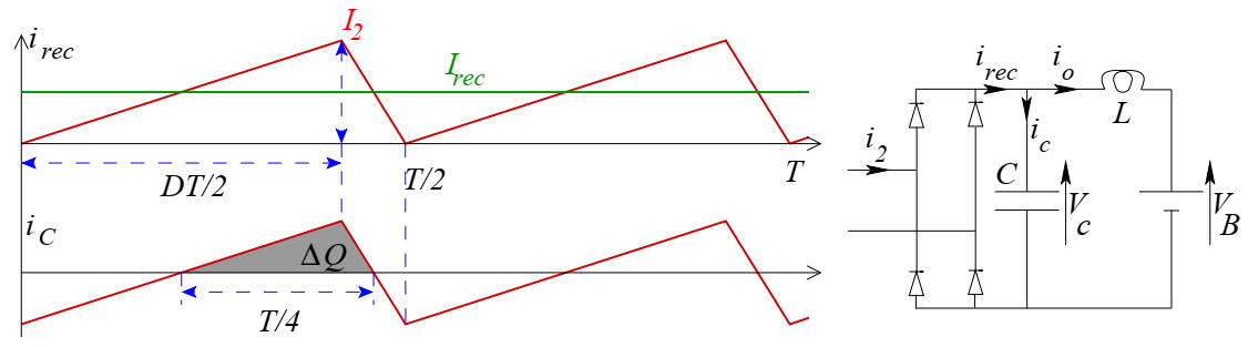
Considering the waveform of the output rectifier current in Figure A1 and applying the power balance between the input ports and the output rectifier port gives rise to (A3):
where and are the average values of the rectifier and DC bus currents respectively, is the number of input ports, and is the converter efficiency. Substituting (A3) into (A2), the filter capacitance is estimated as follows:
Assuming a 90% converter efficiency and using the system parameters given in Table 2 and Table 3, the required filter capacitance to limit the output voltage ripple at 5% is 16.7 μF, as calculated from (A4). Therefore, a 22 μF capacitor filter is selected.
The filter inductance L is designed to limit the ripple component of the current fed to the DC bus io. It is worth mentioning that is the ripple component that failed to be absorbed by the capacitor. Since the fundamental frequency of is 2f, similar to ic in Figure A1, can be calculated from:
Equations (A3) and (A4) are substituted into (A5) to express the percentage output current ripple as follows:
Finally, the filter inductance is calculated:
According to (A7), a 1 mH filter inductance is used to limit the output current ripple below 0.5%.
References
- Periyanayagam, M.; Kumar, V.S.; Chokkalingam, B.; Padmanaban, S.; Mihet-Popa, L.; Adedayo, Y. A Modified High Voltage Gain Quasi-Impedance Source Coupled Inductor Multilevel Inverter for Photovoltaic Application. Energies 2020, 13, 874. [Google Scholar] [CrossRef] [Green Version]
- Hwang, D.-H.; Lee, J.-Y.; Cho, Y. Single-phase single-stage dual-buck photovoltaic inverter with active power decoupling strategy. Renew. Energy 2018, 126, 454–464. [Google Scholar] [CrossRef]
- Hamed, A.S.; Marei, M.I.; Badr, M.A. PV interfacing system based on dual cascaded inverter. In Proceedings of the 2017 IEEE 6th International Conference on Renewable Energy Research and Applications (ICRERA), San Diego, CA, USA, 5 November 2017; pp. 93–100. [Google Scholar]
- Abdalla, I.I.; Corda, J.; Zhang, L. Multilevel DC-Link Inverter and Control Algorithm to Overcome the PV Partial Shading. IEEE Trans. Power Electron. 2012, 28, 14–18. [Google Scholar] [CrossRef]
- Mokhtar, M.; Marei, M.I.; El-Sattar, A.A. An adaptive droop control scheme for DC microgrids integrating sliding mode voltage and current controlled boost converters. IEEE Trans. Smart Grid 2017, 10, 1685–1693. [Google Scholar] [CrossRef]
- Leuenberger, D.; Biela, J. PV-Module-Integrated AC Inverters (AC Modules) with Subpanel MPP Tracking. IEEE Trans. Power Electron. 2017, 32, 6105–6118. [Google Scholar] [CrossRef]
- Guo, K.; Liu, Q.; Xi, X.; Mao, M.; Wan, Y.; Wu, H. Coordinated Control Strategy of a Combined Converter in a Photovoltaic DC Boost Collection System under Partial Shading Conditions. Energies 2020, 13, 474. [Google Scholar] [CrossRef] [Green Version]
- Costanzo, L.; Vitelli, M. A Novel MPPT Technique for Single Stage Grid-Connected PV Systems: T4S. Energies 2019, 12, 4501. [Google Scholar] [CrossRef] [Green Version]
- Qoria, T.; Li, C.; Oue, K.; Gruson, F.; Colas, F.; Guillaud, X. Direct AC voltage control for grid-forming inverters. J. Power Electron. 2020, 20, 198–211. [Google Scholar] [CrossRef]
- Jiang, Y.; Gao, F.; Pan, J. Single-phase Phase-shift Full-bridge Photovoltaic Inverter with Integrated Magnetics. Electr. Power Compon. Syst. 2010, 38, 832–850. [Google Scholar] [CrossRef]
- Marei, M.I.; Alajmi, B.N.; Abdelsalam, I.; Alhajri, M.F. A PV interface system based on high-gain high-frequency link con-verter. In Proceedings of the 2018 53rd International Universities Power Engineering Conference (UPEC), Glasgow, Scotland, UK, 4–7 September 2018; pp. 1–6. [Google Scholar]
- Karthikeyan, V.; Gupta, R. Varying phase angle control in isolated bidirectional DC–DC converter for integrating battery storage and solar PV system in standalone mode. IET Power Electron. 2017, 10, 471–479. [Google Scholar] [CrossRef]
- El-Helw, H.M.; Al-Hasheem, M.; Marei, M.I. Control Strategies for the DAB Based PV Interface System. PLoS ONE 2016, 11, e0161856. [Google Scholar] [CrossRef]
- Marei, M.I.; Elsayad, N.; El-Sattar, A.A. PV interface system with LVRT capability based on a current controlled HFAC link converter. Sustain. Energy Technol. Assess. 2015, 9, 55–62. [Google Scholar] [CrossRef]
- Moosavi, M.; Toliyat, H.A. A Scalable Soft-Switching Photovoltaic Inverter with Cascaded H-Bridge Cells and Galvanic Isolation. In Proceedings of the 2019 IEEE Applied Power Electronics Conference and Exposition (APEC), Anaheim, CA, USA, 17–21 March 2019; pp. 3230–3237. [Google Scholar]
- Iyer, K.V.; Baranwal, R.; Mohan, N. A High-Frequency AC-Link Single-Stage Asymmetrical Multilevel Converter for Grid Integration of Renewable Energy Systems. IEEE Trans. Power Electron. 2017, 32, 5087–5108. [Google Scholar] [CrossRef]
- Islam, R.; Guo, Y.; Zhu, J. A High-Frequency Link Multilevel Cascaded Medium-Voltage Converter for Direct Grid Integration of Renewable Energy Systems. IEEE Trans. Power Electron. 2014, 29, 4167–4182. [Google Scholar] [CrossRef]
- Essakiappan, S.; Krishnamoorthy, H.S.; Enjeti, P.; Balog, R.S.; Ahmed, S. Multilevel Medium-Frequency Link Inverter for Utility Scale Photovoltaic Integration. IEEE Trans. Power Electron. 2015, 30, 3674–3684. [Google Scholar] [CrossRef]
- Romero-Cadaval, E.; Spagnuolo, G.; Franquelo, L.G.; Ramos-Paja, C.A.; Suntio, T.; Xiao, W.M. Grid-Connected Photovoltaic Generation Plants: Components and Operation. IEEE Ind. Electron. Mag. 2013, 7, 6–20. [Google Scholar] [CrossRef] [Green Version]
- Ayang, A.; Saad, M.; Ouhrouche, M.; Wamkeue, R. Modeling, P&O MPPT and PI controls and performance analysis of PV/Energy storage hybrid power system. In Proceedings of the 2018 4th International Conference on Renewable Energies for Developing Countries (REDEC); Institute of Electrical and Electronics Engineers (IEEE): New York, NY, USA, 2018; pp. 1–6. [Google Scholar]
- Gunasekaran, D.; Umanand, L. Integrated magnetics based multi-port bidirectional DC–DC converter topology for discontinuous-mode operation. IET Power Electron. 2012, 5, 935–944. [Google Scholar] [CrossRef]
- Jakka, V.N.S.R.; Shukla, A.; Demetriades, G.D. Dual-Transformer-Based Asymmetrical Triple-Port Active Bridge (DT-ATAB) Isolated DC–DC Converter. IEEE Trans. Ind. Electron. 2017, 64, 4549–4560. [Google Scholar] [CrossRef]
- Buticchi, G.; Costa, L.F.; Barater, D.; Liserre, M.; Amarillo, E.D. A Quadruple Active Bridge Converter for the Storage Integration on the More Electric Aircraft. IEEE Trans. Power Electron. 2017, 33, 8174–8186. [Google Scholar] [CrossRef] [Green Version]
- Jafari, M.; Malekjamshidi, Z.; Lu, D.D.-C.; Zhu, J. Development of a Fuzzy-Logic-Based Energy Management System for a Multiport Multioperation Mode Residential Smart Microgrid. IEEE Trans. Power Electron. 2019, 34, 3283–3301. [Google Scholar] [CrossRef]
- Hebala, O.M.; Aboushady, A.A.; Ahmed, K.H.; Abdelsalam, I.; Burgess, S.J. A New Active Power Controller in Dual Active Bridge DC–DC Converter with a Minimum-Current-Point-Tracking Technique. IEEE J. Emerg. Sel. Top. Power Electron. 2021, 9, 1328–1338. [Google Scholar] [CrossRef]
- Shao, S.; Chen, H.; Wu, X.; Zhang, J.; Sheng, K. Circulating Current and ZVS-on of a Dual Active Bridge DC-DC Converter: A Review. IEEE Access 2019, 7, 50561–50572. [Google Scholar] [CrossRef]
- Qi, J.; Zhang, Y.; Chen, Y. Modeling and maximum power point tracking (MPPT) method for PV array under partial shade condi-tions. Renew. Energy 2014, 66, 337–345. [Google Scholar] [CrossRef]
- Al-Emam, M.; Marei, M.I.; El-khattam, W. A Maximum Power Point Tracking Technique for PV Under Partial Shading Condition. In Proceedings of the 2018 8th IEEE India International Conference on Power Electronics (IICPE), Jaipur, India, 13–15 December 2018; pp. 1–6. [Google Scholar]
- Alajmi, B.; Marei, M.I.; Abdelsalam, I. A Multi-Port DC/DC Converter based on Two- Quadrant Inverter Topology for PV Systems. IEEE Trans. Power Electron. 2021, 36, 522–532. [Google Scholar] [CrossRef]
- Ali, A.I.; Sayed, M.A.; Mohamed, E.E. Modified efficient perturb and observe maximum power point tracking technique for grid-tied PV system. Int. J. Electr. Power Energy Syst. 2018, 99, 192–202. [Google Scholar] [CrossRef]
- Khan, M.J.; Mathew, L. Comparative study of maximum power point tracking techniques for hybrid renewable energy system. Int. J. Electron. 2019, 106, 1216–1228. [Google Scholar] [CrossRef]
- Sunpower SPR-305-WHT-U (305) Solar Panel. Available online: http://www.solardesigntool.com/components/module-panel-solar/Sunpower/514/SPR-305-WHT-U/specification-data-sheet.html (accessed on 20 January 2021).
- Andersson, C. Design of a 2.5 kW DC-DC Full Bridge Converter. Master’s Thesis, Chalmers University of Technology, Göteborg, Sweden, 2011. [Google Scholar]
- Pereda, J.; Dixon, J. High-Frequency Link: A Solution for Using Only One DC Source in Asymmetric Cascaded Multilevel Inverters. IEEE Trans. Ind. Electron. 2011, 58, 3884–3892. [Google Scholar] [CrossRef]
Figure 1.
Proposed HFMP DC-DC converter for the PV interfacing system. (a) MP DC-DC converter. (b) Gating signals for the proposed MP DC-DC converter.
Figure 1.
Proposed HFMP DC-DC converter for the PV interfacing system. (a) MP DC-DC converter. (b) Gating signals for the proposed MP DC-DC converter.
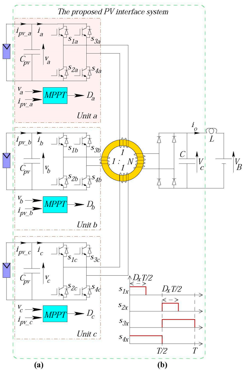
Figure 2.
Equivalent circuits for different modes of operation of the proposed interfacing system at the positive half-cycle.(a) Mode 1 equivalent circuit, (b) Mode 2 equivalent circuit, (c) Mode 3 equivalent circuit, (d) Mode 4 equivalent circuit, (e) Mode 5 equivalent circuit,.
Figure 2.
Equivalent circuits for different modes of operation of the proposed interfacing system at the positive half-cycle.(a) Mode 1 equivalent circuit, (b) Mode 2 equivalent circuit, (c) Mode 3 equivalent circuit, (d) Mode 4 equivalent circuit, (e) Mode 5 equivalent circuit,.

Figure 3.
Operating waveforms of the HFMP converter.
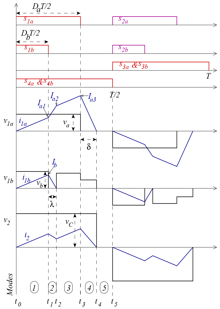
Figure 4.
Performance of the proposed high-frequency multi-port DC-DC converter fed from two identical DC sources. (a) Voltages in the windings. (b) Current in the windings. (c) DC-side input current.
Figure 4.
Performance of the proposed high-frequency multi-port DC-DC converter fed from two identical DC sources. (a) Voltages in the windings. (b) Current in the windings. (c) DC-side input current.

Figure 5.
Photovoltaic module characteristics at different irradiance levels.
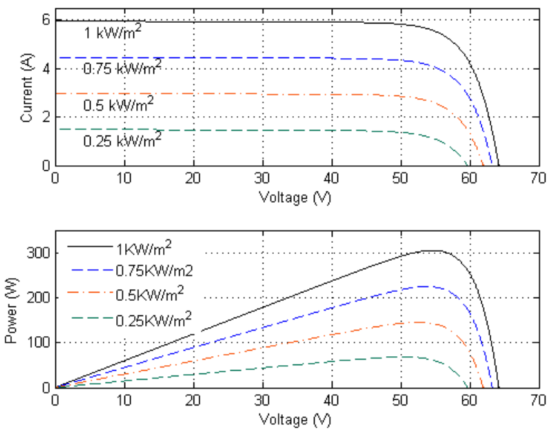
Figure 6.
Results of the proposed HFMP converter with three photovoltaic modules. (a) Irradiance levels. (b) Output PV power. (c) Duty cycles.
Figure 6.
Results of the proposed HFMP converter with three photovoltaic modules. (a) Irradiance levels. (b) Output PV power. (c) Duty cycles.

Figure 7.
Results of the proposed high-frequency multi-port converter with three PV modules. (a) Voltages. (b) Current of the three PV units. (c) Output power to the DC bus.
Figure 7.
Results of the proposed high-frequency multi-port converter with three PV modules. (a) Voltages. (b) Current of the three PV units. (c) Output power to the DC bus.

Figure 8.
High frequency transformer input winding voltages and currents. (a) Transformer input winding voltage, (b) transformer output winding voltage, (c) transformer input winding current, (d) transformer output winding current.
Figure 8.
High frequency transformer input winding voltages and currents. (a) Transformer input winding voltage, (b) transformer output winding voltage, (c) transformer input winding current, (d) transformer output winding current.
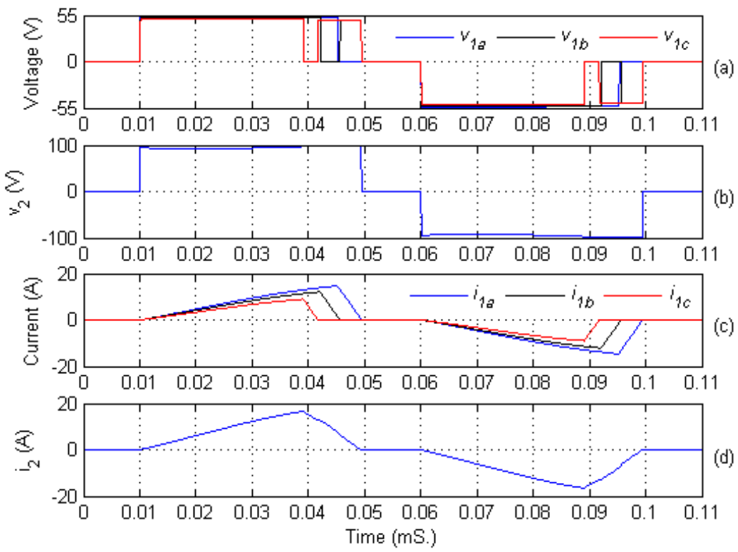
Figure 9.
The experimental setup.
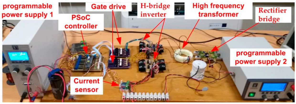
Figure 10.
Voltages across windings of the proposed system fed from DC supplies with different duty cycles for each unit.
Figure 10.
Voltages across windings of the proposed system fed from DC supplies with different duty cycles for each unit.
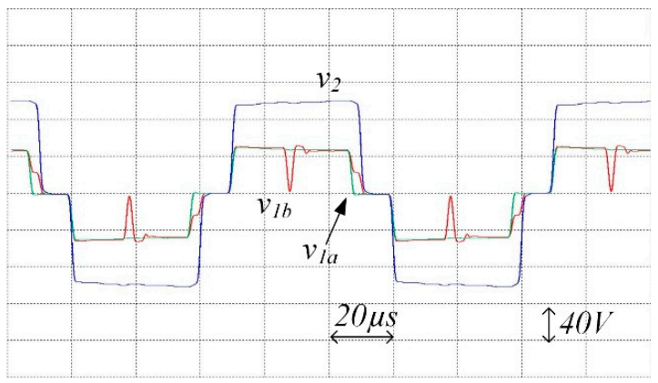
Figure 11.
Currents through windings of the proposed system fed from DC supplies with different duty cycles for each unit.
Figure 11.
Currents through windings of the proposed system fed from DC supplies with different duty cycles for each unit.

Figure 12.
Voltages across windings of the proposed system fed from PPSs emulating PV modules at the rated condition.
Figure 12.
Voltages across windings of the proposed system fed from PPSs emulating PV modules at the rated condition.

Figure 13.
Currents through windings of the proposed system fed from PPSs emulating PV modules at the rated condition.
Figure 13.
Currents through windings of the proposed system fed from PPSs emulating PV modules at the rated condition.

Figure 14.
Voltages across windings of the proposed system fed from PPSs emulating PV modules.

Figure 15.
Currents through windings of the proposed system fed from PPSs emulating PV modules.

Table 1.
The perturb and observe procedure.
| Variation in vx | Variation in Power | Dx |
|---|---|---|
| + | + | Dx − ΔD |
| + | − | Dx + ΔD |
| − | + | Dx + ΔD |
| − | − | Dx − ΔD |
Table 2.
The converter parameters.
| Input port voltage | 55 V |
| Average input port current | 5.6 A |
| Average output port current | 5.6 A |
| DC bus voltage, vB | 90 V |
| Turns ratio | 10:10:20 |
| L1a = L1b = L1 | 7.25 μH |
| L2 | 29 μH |
| L | 1 mH |
| C | 22 μF |
| Switching frequency | 10 kHz |
Table 3.
Photovoltaic module specifications.
| PV Module Specifications [32] | |
|---|---|
| Model | Sunpower SPR-305-WHT |
| Maximum Power | 305 W at STC |
| Number of Cells | 96 |
| Current at MPP | 5.58 A |
| Voltage at MPP | 54.7 V |
| Open Circuit Voltage | 64.2 V |
| Short Circuit Current | 5.96 A |
Table 4.
The voltage and power measured at the terminals of the programed power supplies (PPS).
| PPS of Unit ‘a’ | PPS of Unit ‘b’ | |
|---|---|---|
| Voltage | 51.8 V | 50.6 V |
| Power | 299 W | 143 W |
Publisher’s Note: MDPI stays neutral with regard to jurisdictional claims in published maps and institutional affiliations. |
© 2021 by the authors. Licensee MDPI, Basel, Switzerland. This article is an open access article distributed under the terms and conditions of the Creative Commons Attribution (CC BY) license (https://creativecommons.org/licenses/by/4.0/).
Share and Cite
MDPI and ACS Style
Alajmi, B.N.; Marei, M.I.; Abdelsalam, I.; AlHajri, M.F. Analysis and Design of a Multi-Port DC-DC Converter for Interfacing PV Systems. Energies 2021, 14, 1943. https://doi.org/10.3390/en14071943
AMA Style
Alajmi BN, Marei MI, Abdelsalam I, AlHajri MF. Analysis and Design of a Multi-Port DC-DC Converter for Interfacing PV Systems. Energies. 2021; 14(7):1943. https://doi.org/10.3390/en14071943
Chicago/Turabian StyleAlajmi, Bader N., Mostafa I. Marei, Ibrahim Abdelsalam, and Mohamed F. AlHajri. 2021. "Analysis and Design of a Multi-Port DC-DC Converter for Interfacing PV Systems" Energies 14, no. 7: 1943. https://doi.org/10.3390/en14071943
Note that from the first issue of 2016, this journal uses article numbers instead of page numbers. See further details here.