
Optimal Radial Build and Transmutation Properties of a Fusion-Based Transmutation Reactor with Molten Salt Coolants

Quantum System Engineering, Jeonbuk National University, Jeonju 54896, Korea
Energies 2022, 15(10), 3667; https://doi.org/10.3390/en15103667
Submission received: 24 April 2022
/
Revised: 16 May 2022
/
Accepted: 16 May 2022
/
Published: 17 May 2022
(This article belongs to the Topic Nuclear Energy Systems)
Abstract
:The optimal shape of a fusion-based transmutation reactor with a molten salt coolant was determined by plasma physics, technology, and neutronic requirements. System parameters such as neutron multiplication, power density, shielding, and tritium breeding, were calculated in a self-consistent manner by coupling neutron transport analysis with conventional tokamak systems analysis. The plasma physics and engineering levels were similar to those used in the International Thermonuclear Experimental Reactor. The influence of aspect ratio of the tokamak and fusion power on the radial build, and the transmutation properties associated with two molten salt options, FLiBe and FliNaBe, were investigated. Being compared with a transmutation reactor with a small aspect ratio, a transmutation reactor with large aspect ratio was smaller in size and had a larger maximum fusion power. This type of reactor also revealed increased tritium-breeding capability and a smaller initial transuranic (TRU) inventory with a slightly lower burn-up rate. The burn-up rate for molten salt using either FLiBe or FLiNaBe was similar, but the initial TRU inventory and the tritium-breeding capability were smaller with FLiNaBe compared with FLiBe.
1. Introduction
The possibility of using a transmutation reactor based on 14.1 MeV fusion neutrons to burn up nuclear waste from spent nuclear fuel has been studied previously [1,2,3,4]. A transmutation reactor not only burns up nuclear waste, but also produces power. Nuclear waste transmutation using fusion neutrons with a molten salt coolant has also been studied [5,6,7]. Two molten salts, FLiBe (a mixture of lithium fluoride and beryllium fluoride) and FLiNaBe (lithium fluoride, sodium fluoride, and beryllium fluoride), exhibit low reactivity and can avoid issues related to magnetohydrodynamic pressure drops due to their high electrical resistivity [2,8,9]. A molten salt can serve as both a carrier of transuranic (TRU) waste and as a coolant, offering the possibility of refueling burned TRU and extracting fission products while online [10]. The components of the transmutation reactor including the reactor, the molten salt flow loop, the heat exchanger, and the thermal conversion system were studied in [10].
The size of a transmutation reactor with a tokamak neutron source needs to be minimized from an economic viewpoint. To determine the optimal radial build, the physics, technology, and neutronic requirements should be satisfied by each component of the reactor. In this study, the physics and technology requirements were similar to those used in the design of the International Thermonuclear Experimental Reactor (ITER) [11,12]. With respect to neutronics, a tritium breeding ratio (TBR) <1.35 in a one-dimensional model with a blanket coverage factor of 80% was necessary to achieve tritium self-sufficiency, while restricting the neutron multiplication factor, keff, below 1.0 to allow for subcritical operation, and restricting the power density below 100 MW/m3 to satisfy cooling requirements. To consistently determine the radial builds of the transmutation reactor components, a radiation transport calculation was coupled with a tokamak systems analysis [13,14], as both fusion and fission neutrons can affect the technology requirements that should be satisfied by each component of the reactor. The TRU can be loaded into the outboard region only because neutrons from fission of the TRU help achieve tritium self-sufficiency. The plasma performance and the shielding requirements are the primary determinants of the inboard radial build, while the requirements for neutron multiplication, power density, and tritium self-sufficiency determine the outboard radial build. The shield should protect the superconducting toroidal field (TF) coil from neutron-induced damage and nuclear heating. In this study, the optimal radial build of a transmutation reactor using molten salt as a coolant, with an aspect ratio ranging from 2.0 to 4.0, and with a maximum fusion power, Pf,max, ranging from 100 to 300 MW, was determined.
In the transmutation reactor, the fission power produced and the TRU transmuted are proportional to Sfusion∙keff/(1 − keff), where Sfusion is the fusion neutron yield and the neutron multiplication factor, keff, increases due to 14.1 MeV fusion neutrons. For the produced power to be a steadily large value, keff needs to be maintained large (close to 1) during the burn-up period, or the fusion power has to increase as the TRU burns up to compensate for the consumption of neutrons. In this study, we investigated the transmutation properties of the transmutation reactor using fusion neutrons and its dependence on the type of molten salt, the aspect ratio, and Pf,max when power production was fixed at 4000 MW.
2. Models and Method of Analysis
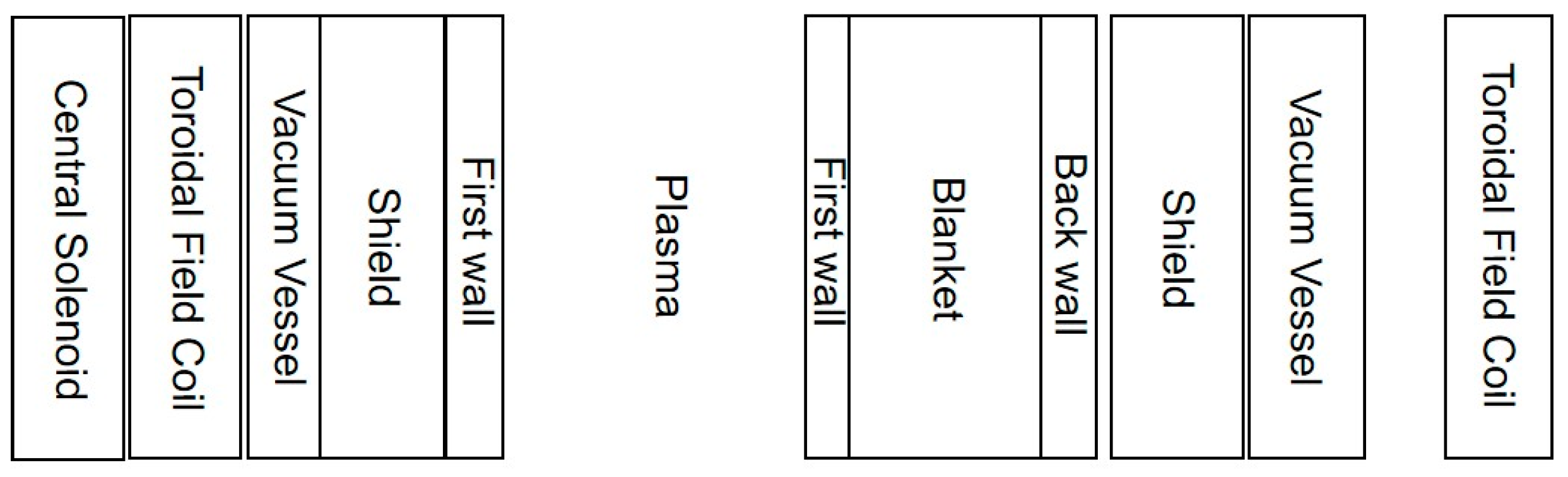
The transmutation reactor was modeled using one-dimensional cylindrical geometry (Figure 1). Table 1 provides the reactor’s radial components and their material composition; the radial components are a central solenoid (CS), TF coil, vacuum vessel, shield, blanket, and plasma. It was assumed that half of a plasma current is driven by a CS, and the rest is driven by a external current drive system. The blanket was placed only in the outboard region of the reactor, and tritium self-sufficiency could be satisfied by the addition of neutrons produced by the fission of the TRU. Natural lithium can therefore be used, whereas 6Li enrichment is necessary in the case of a fusion reactor.
Both magnetic coils (TF and CS) were made of SUS316 stainless steel, Nb3Sn, copper, an organic insulator, and liquid helium, and its assumed winding-pack current density was 25 MA/m2. The allowable magnetic field, Bmax, was assumed to be 16 T [15]. The vacuum vessel was made of water-cooled borated stainless steel with a thickness of 0.1 m. The shield was water-cooled, made of ferritic martensitic steel (FMS) and filled with tungsten carbide. Sufficient thickness was necessary to protect the superconducting TF coil from neutron-induced damage, and the shielding requirements were fast neutron fluence to a superconductor below 1023 n/m2 for Nb3Sn and 1027 n/m2 for the FMS fast wall, displacement damage to the copper stabilizer below 5 × 10⁻⁴ dpa, and a dose to the insulators below 109 rad for the organic insulator. The lifetime of the transmutation reactor was assumed to be 40 years, with an expected availability of 75%. Sufficient thickness for the blanket was required to satisfy the tritium self-sufficiency and to restrict the power density below 100 MW/m3. To determine the radial build of the blanket and the shield, the keff, power density, TBR, and radiation damages on the TF coil should be calculated. The TRU from the spent fuel of a Korea Standard Nuclear Power Plant [16] with a capacity of 1 GWe was dissolved in molten salt and loaded into the blanket, which were comprised of FMS coated with SiC as a structural material and molten salt as a coolant. For the molten salt, FLiBe and FLiNaBe were used. The first wall with a thickness of 2.0 cm was made of FMS, tungsten was used as armor material, and it was water-cooled. Beryllium was used as a neutron multiplier in the case of FLiNaBe to increase the TBR. The FW should be replaced depending on the accumulated fast neutron fluence limit, which was assumed to be 3.0 × 1027 n/m2 for the FMS.
In tokamak plasma, its performance is typically characterized by a beta limit, a density limit, and a plasma current. The dependence of the maximum elongation, κ, on aspect ratio, A, was assumed as [17], and the dependence of the maximum βN () on the aspect ratio and the elongation was assumed as [18]:
For the energy confinement time, τE, the H-mode IPB98y2 scaling law [12] was applied, with a confinement enhancement factor, H, of
To determine the minimum major radius, R0, and the optimal radial build of the transmutation reactor, the physics, technology, and neutronic requirements should be satisfied at once by each component of the reactor. Table 2 lists the requirements for this study. Addition of neutrons from the fission of the TRU increased the shield thickness compared with the case without TRU. For this purpose, radiation transport analysis was coupled to the conventional tokamak systems analysis. For the one-dimensional radiation transport analysis, BISON-C code [22] was used, with a cross section library based on JENDL-3 [23]. The dependence of the R0 on BT was determined by the plasma performance. Given the plasma performance, as BT increased, R0 decreased. For a given BT, the shield thickness was determined to satisfy the shielding requirements for the superconducting coils. The contribution of reflected neutrons from the shield to the TBR and contribution of the blanket to the shielding were both considered. Ampere’s law and stress requirements determined the TF coil thickness. The ripple requirement determined the position of the outer TF coil. The CS thickness was determined depending on how the plasma current was driven. As BT increased, the shield thickness increased due to increased neutron wall-loading, the TF coil thickness increased due to decreased winding-pack current density, and the CS bore radius, Rbore, decreased. The minimum R0, the maximum BT, and the optimal build were determined when the Rbore or Bmax at the TF coil reached its limiting value.
3. Results
The optimal radial build and transmutation properties of transmutation reactors with two molten salts, FLiBe and FLiNaBe, with an aspect ratio ranging from 2.0 to 4.0, were investigated for Pf,max values of 100 MW, 200 MW, and 300 MW. The minimum R0 was determined to produce the given Pf,max with κ = 0.9 κmax, a triangularity of δ = 0.5, a normalized plasma beta of βN = 0.7⋅βN,max, H = 1.2, an edge safety factor of qe = 4.0, and a line-averaged electron density, , of 0.7⋅nG, where nG is the Greenwald density limit.
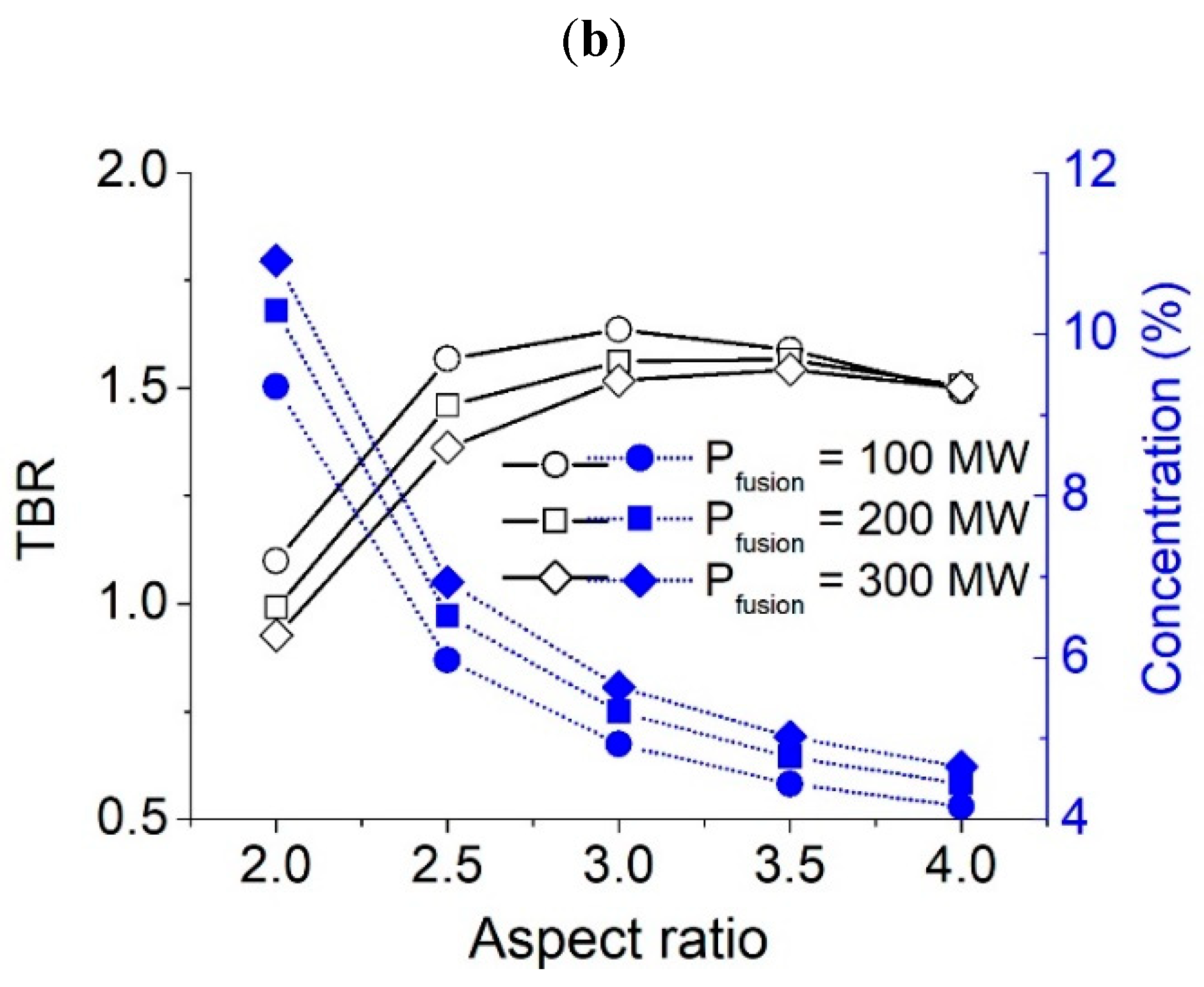
The impact of A on the minimum R0, neutron wall-loading, initial TBR, and initial TRU concentration when Pf,max = 100 MW, 200 MW, and 300 MW is shown in Figure 2 for FLIBE, and in Figure 3 for FLiNaBe. Both figures show that, for a given Pf,max, the minimum R0 decreased and the neutron wall-loading increased with A, and both parameters increased as Pfusion increased; the maximum neutron wall-loading was less than 1.1 MW/m2, implying that the fast neutron fluence limit at the first wall would be satisfied during the lifetime of the reactor with few replacements; the initial TBR increased sharply at the beginning but decreased gradually as A increased; the initial TBR was large for a small Pfusion when A was small, but its dependence on Pfusion weakened; the initial TRU concentration to satisfy a keff requirement of 0.95 decreased as A increased, and was large when Pf,max was large.
Figure 4 shows the optimal radial build of the transmutation reactor for (a) A = 2.0 with Pf,max = 100 MW in comparison to (b) A = 4.0 with Pf,max = 300 MW. In the case of (a), the required magnetic field at the plasma center (BT) was smaller, resulting in a larger major radius; the CS thickness was larger due to the greater plasma current, and the TF coil thickness was smaller due to the smaller magnetic field at the plasma center (BT); the inboard shield thickness was smaller due to smaller neutron wall-loading; the outboard blanket thickness was smaller for a given power density; and the distance between the vacuum vessel and the outer TF coil to satisfy the ripple requirement (maximum ripple <0.5%) was larger than those for case (b). As a result, the system dimension of case (b) was smaller than that of case (a).
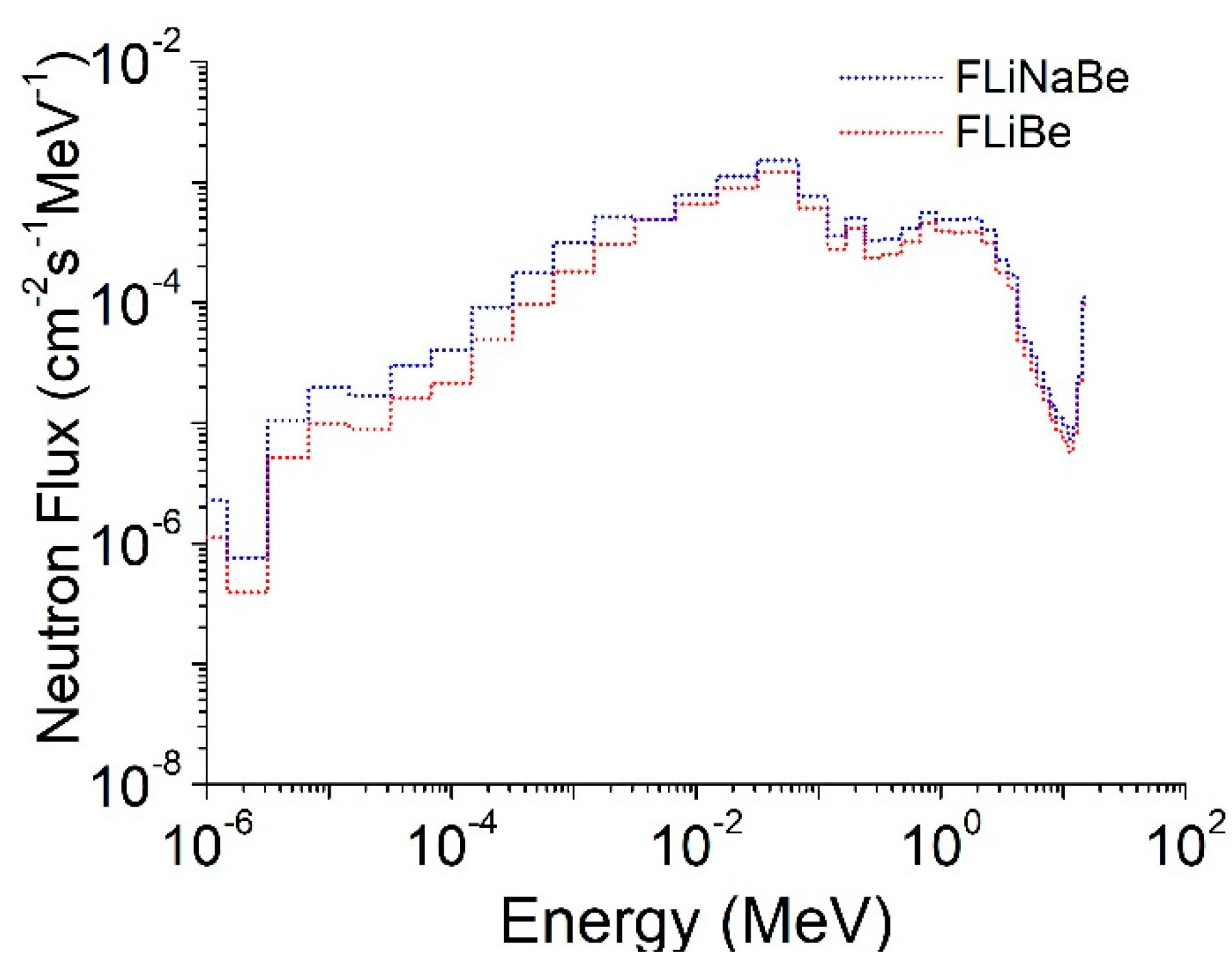
In Table 3 and Table 4, system parameters and the transmutation properties for various values of A when Pf,max = 200 MW and Pf,max = 300 MW are shown. The variation of keff, necessary fusion power, and TBR as the TRU burned up are shown in Figure 5 when using FLiBe, and in Figure 6 using FLiNaBe. The reactor height was assumed to be κ·a (where κ is an elongation and a is a minor radius). κ and a decreased as A increased, increasing outboard blanket thickness, ∆blo, to satisfy a power density limit of 100 MW/m3. Neutron multiplication (keff) decreased as the TRU burned up, and the fusion power increased to compensate for the consumption of neutrons as the TRU burned up to produce constant power. The reactor with a Pf,max value of 100 MW could not be used as its required fusion power was greater than 100 MW. The keff increased initially and then decreased as the TRU burned up, and its dependence on A was weak. The decrease in the rate of keff was greater for the reactor with a smaller Pf,max. The initial TRU concentration and the initial TRU inventory decreased with A, and they were smaller in the case of FLiNaBe than those in the case of FLiBe. The burn-up rate, defined as the burned-up TRU mass per year, ranged from 1129 kg/yr to 1155 kg/yr, which can support more than four pressurized water reactors (PWRs), assuming that the TRU from 1 PWR with a 1 GWe capacity is approximately 250 kg/y. This value decreased slightly with A, but little dependence on the Pf,max was seen. Additionally, the burn-up rate showed little dependence on the molten salt type, although the initial TRU concentration in the case of FLiNaBe was smaller than that in the case of FLiBe. This result attributed to the fact that fission reaction rates of the TRU were similar due to larger neutron flux in the case of FLiNaBe, as seen in Figure 7, which compares neutron energy spectra. For the reactor cooled by FLiBe and a Pf,max of 200 MW, the required fusion power reached 200 MW at a burn-up period of 600 days when A = 3.5, and the required fusion power was larger than 200 MW from the initial burn-up when A = 4.0; for the reactor cooled with FLiNaBe and a Pf,max = 200 MW, the required fusion power reached 200 MW at a burn-up period of 930 days when A = 3.5 and 750 days when A = 4.0. The TBR increased initially, then decreased as the TRU burned up. When FLiNaBe was used, the initial TBR was smaller than in the case of FliBe due to small lithium density. For the reactor with a FliNaBe coolant, the TBR was too small when A = 2.0. The fast neutron fluence of the first wall for the reactor with a large A was larger than that with the small A due to greater neutron wall-loading for the former. It was relatively large for the reactor cooled with FliNaBe. The FW should be replaced once within the reactor lifetime for a reactor cooled with FliNaBe, and when A > 3.0 for the reactor cooled with FLiBe to satisfy the fast neutron fluence limit of the FMS.
4. Summary
The optimal radial build of a fusion-based transmutation reactor with a molten salt coolant was determined with an aspect ratio ranging from 2.0 to 4.0, and with a maximum fusion power, Pf,max, ranging from 100 to 300 MW. It was determined by coupling neutron transport analysis with conventional tokamak systems analysis with plasma physics, technology, and neutronic requirements. System parameters, neutron multiplication, power density, shielding, and tritium breeding that satisfy all requirements at once were calculated in a self-consistent manner.
We investigated the transmutation properties of the transmutation reactor using fusion neutrons and its dependence on the type of molten salt coolant, aspect ratio, and Pf,max of a transmutation reactor that produced power fixed at 4000 MW. We found that the burn-up rate had little dependence on aspect ratio, Pf,max, or the type of molten salt, and it ranged from 1129 kg/yr to 1155 kg/yr, which is sufficient to accommodate the TRU from more than 4 PWRs with a capacity of 1 GWe each. A transmutation reactor with a large aspect ratio revealed a smaller size with larger Pf,max, a larger tritium-breeding capability, and a smaller initial TRU inventory with a slightly lower burn-up rate compared with a transmutation reactor with a small aspect ratio; the burn-up rate with both FLiBe and FLiNaBe molten salt was similar, but with FLiNaBe, the initial TRU inventory and tritium-breeding capability were smaller than it was in the case with FLiBe.
Funding
This work was supported by research funds from Jeonbuk National University in 2022, and a National Research Foundation of Korea (NRF) grant under contract No. 2021R1F1A1045388.
Institutional Review Board Statement
Not applicable.
Informed Consent Statement
Not applicable.
Data Availability Statement
Not applicable.
Acknowledgments
This work was also supported by research facilities at the Plasma Application Institute of Jeonbuk National University.
Conflicts of Interest
The author declares no conflict of interest.
References
- Wu, Y.; Zheng, S.; Zhu, X.; Wang, W.; Wang, H.; Liu, S.; Bai, Y.; Chen, H.; Hu, L.; Chen, M.; et al. Conceptual design of the fusion-driven subcritical system FDS-I. Fusion Eng. Des. 2006, 81, 1305. [Google Scholar] [CrossRef]
- Stacey, W.M. Transmutation missions for fusion neutron sources. Fusion Eng. Des. 2007, 82, 11–20. [Google Scholar] [CrossRef]
- Stacey, W.M. Solving the spent nuclear fuel problem by fissioning transuranics in subcritical advanced burner reactors driven by tokamak neutron sources. Nucl. Technol. 2017, 200, 15–26. [Google Scholar] [CrossRef]
- Hong, B.G. Effect of tokamak neutron source shape on radwaste transmutation. Fusion Eng. Des. 2019, 147, 111220. [Google Scholar] [CrossRef]
- Cheng, E.T.; Cerbone, R.J. Prospect of nuclear waste transmutation and power production in fusion reactors. Fusion Technol. 1996, 30, 1654. [Google Scholar] [CrossRef]
- Gohar, Y. Fusion Option to Dispose of Spent Nuclear Fuel and Transuranic Elements; Argonne National Laboratory Report ANL/TD/TM00-09; Argonne National Laboratory: Lemont, IL, USA, 2000. [Google Scholar]
- Zou, J.; Zhao, J.; Wei, C.; Liu, Z. Minor actinides transmutation in a molten salt blanket in the fusion-fission hybrid reactor core. Fusion Eng. Des. 2020, 158, 111863. [Google Scholar] [CrossRef]
- Moriyama, H.; Sagara, A.; Tanaka, S.; Moir, R.W.; Sze, D.K. Molten salts in fusion nuclear technology. Fusion Eng. Des. 1998, 39–40, 627–637. [Google Scholar] [CrossRef]
- Williams, D.F.; Toth, L.M.; Clarno, K.T. Assessment of Candidate Molten Salt Coolants for the Advanced High-Temperature Reactor (AHTR); Report, ORNL/TM-2006/12; Oak Ridge National Laboratory: Oak Ridge, TN, USA, 2006. [Google Scholar]
- Woolley, R.D. System Studies of Fission-Fusion Hybrid Molten Salt Reactors. Ph.D. Thesis, University of Tennessee, Knoxville, TN, USA, 2013. Available online: http://trace.tennessee.edu/utk_graddiss/2628 (accessed on 1 April 2022).
- Holtkamp, N. The status of the ITER design. Fusion Eng. Des. 2009, 84, 98. [Google Scholar] [CrossRef]
- Ikeda, N. Progress in the ITER Physics Basis. Nucl. Fusion 2007, 47, E01. [Google Scholar] [CrossRef]
- Hong, B.G.; Kim, T.H. On the optimal radial build of a normal aspect ratio tokamak fusion system. Fusion Eng. Des. 2019, 139, 148–154. [Google Scholar] [CrossRef]
- Hong, B.G.; Hwang, Y.S.; Kang, J.S.; Lee, D.W.; Joo, H.G.; Ono, M. Conceptual design study of a superconducting spherical tokamak reactor with a self-consistent system analysis code. Nucl. Fusion 2011, 51, 113013. [Google Scholar] [CrossRef] [Green Version]
- Kim, K.; Oh, S.; Park, J.S.; Lee, C.; Im, K.; Kim, H.C.; Lee, G.S.; Neilson, G.; Brown, T.; Kessel, C.; et al. Conceptual design study of the K-DEMO magnet system. Fusion Eng. Des. 2015, 96–97, 281–285. [Google Scholar] [CrossRef]
- Song, K.C.; Lee, H.S.; Hur, J.M.; Kim, J.G.; Ahn, D.H.; Cho, Y.Z. Status of Pyroprocessing Technology Development in Korea. Nucl. Eng. Technol. 2010, 42, 131. [Google Scholar] [CrossRef] [Green Version]
- Stambaugh, R.D.; Lao, L.L.; Lazarus, E.A. Relation of vertical stability and aspect ratio in tokamaks. Nucl. Fusion 1992, 32, 1642. [Google Scholar] [CrossRef]
- Lin-Liu, Y.R.; Stambaugh, R.D. Optimum equilibria for high performance, steady state tokamaks. Nucl. Fusion 2004, 44, 548. [Google Scholar] [CrossRef]
- Perkins, F.; Barabaschi, P.; Boucher, D. ITER Physics Basis. Nucl. Fusion 1999, 39, 2137. [Google Scholar]
- Hong, B.G.; Lee, D.W.; In, S.R. Tokamak reactor system analysis code for the conceptual development of demo reactor. Nucl. Eng. Technol. 2008, 40, 87–92. [Google Scholar] [CrossRef] [Green Version]
- Kovari, M.; Kemp, R.; Lux, H.; Knight, P.; Morris, J.; Ward, D.J. “PROCESS”: A systems code for fusion power plants—Part 1: Physics. Fusion Eng. Des. 2014, 89, 3054–3069. [Google Scholar] [CrossRef]
- ORNL. BISON-C; Oak Ridge National Laboratory Report, CCC-659; Oak Ridge National Laboratory: Oak Ridge, TN, USA, 1998. [Google Scholar]
- Nakagawa, T.; Shibata, K.; Chiba, S.; Fukahori, T.; Nakajima, Y.; Kikuchi, Y.; Kanda, Y.; Ohsawa, T.; Matsunobu, H.; Kawai, M.; et al. Japanese evaluated nuclear data library version 3 reversion-2: JENDL-3.2. J. Nucl. Sci. Technol. 1995, 32, 1259. [Google Scholar] [CrossRef]
Figure 1.
Transmutation reactor model in one-dimensional cylindrical geometry.

Figure 2.
The impacts of the aspect ratio on (a) the minimum R0 and the neutron wall loading; (b) initial TBR and initial TRU concentration for FLiBe.
Figure 2.
The impacts of the aspect ratio on (a) the minimum R0 and the neutron wall loading; (b) initial TBR and initial TRU concentration for FLiBe.

Figure 3.
The impacts of the aspect ratio on (a) the minimum R0 and the neutron wall loading; (b) initial TBR and initial TRU concentration for FLiNaBe.
Figure 3.
The impacts of the aspect ratio on (a) the minimum R0 and the neutron wall loading; (b) initial TBR and initial TRU concentration for FLiNaBe.


Figure 4.
Optimal radial build of the transmutation reactor for (a) A = 2.0 with Pf,max = 100 MW, and (b) A = 4.0 with Pf,max = 300 MW, where TFC: toroidal field coil, CS: central solenoid, VV: vacuum vessel, and A: aspect ratio.
Figure 4.
Optimal radial build of the transmutation reactor for (a) A = 2.0 with Pf,max = 100 MW, and (b) A = 4.0 with Pf,max = 300 MW, where TFC: toroidal field coil, CS: central solenoid, VV: vacuum vessel, and A: aspect ratio.

Figure 5.
Variation of (a,c) keff and necessary fusion power, and (b,d) TBR as the TRU burned up with FLiBe. (a,b) Pf,m = 200 MW; (c,d) Pf,m = 300 MW.
Figure 5.
Variation of (a,c) keff and necessary fusion power, and (b,d) TBR as the TRU burned up with FLiBe. (a,b) Pf,m = 200 MW; (c,d) Pf,m = 300 MW.

Figure 6.
Variation of (a,c) keff and necessary fusion power, and (b,d) TBR as the TRU burned up with FLiNaBe. (a,b) Pf,m = 200 MW; (c,d) Pf,m = 300 MW.
Figure 6.
Variation of (a,c) keff and necessary fusion power, and (b,d) TBR as the TRU burned up with FLiNaBe. (a,b) Pf,m = 200 MW; (c,d) Pf,m = 300 MW.

Figure 7.
Comparison of the neutron energy spectrum with FLiBe and with FLiNaBe.


Table 1.
The reactor’s radial components and material compositions.
| Component | Materials (Volume %) |
|---|---|
| Central solenoid | L. He, Nb3Sn, Cu, Epoxy, SUS316 |
| Toroidal field coil | L. He, Nb3Sn, Cu, Epoxy, SUS316 |
| Vacuum vessel | Borated steel (60), H2O (40) |
| Shield | Ferritic Martensitic steel (20), WC (60), H2O (20) |
| First wall | FMS (60/30), Be (0/30), H2O (40) |
| Plasma | D, T |
| First wall | FMS (60/30), Be (0/30), H2O (40) |
| Transmutation blanket | Transuranics (TBD), FLiBe/FLiNaBe (TBD), Ferritic Martensitic steel (15), SiC (5) |
| Shield | FMS (20), WC (60), H2O (20) |
| Vacuum vessel | Borated steel (60), H2O (40) |
| Toroidal field coil | L. He, Nb3Sn, Cu, Epoxy, SUS316 |
Table 2.
Plasma physics, technology and neutronic requirements.
| Plasma Physics Requirements | |
|---|---|
| βN < βN,max ne < nG Pcon + PBrem = Paux + Pa Pf,max = desired power ripple < 0.5% |
| Technology and neutronics requirements | |
| Bmax × RTFi = R0 × BT JTF < 2.5 × 10⁷ A/m2 σTFcase < 550 MPa |
| tritium breeding ratio >1.35 neutron multiplication <0.95 (initial) power density <100 MW/m3 fast neutron fluence <1023 n/m2 (@SC), 1027 n/m2 (@FW) displacement damage <5 × 10⁻⁴ dpa dose to the insulators <109 rad |
Table 3.
System parameters and transmutation properties for various A and Pf,max with FLiBe.
| Aspect Ratio Pf,max (MW) | 2.0 | 2.5 | 3.0 | 3.5 | 4.0 | |
|---|---|---|---|---|---|---|
| 200 | R0 (m) | 4.45 | 3.79 | 3.57 | 3.50 | 3.47 |
| Minor radius, a (m) | 2.23 | 1.51 | 1.19 | 1.00 | 0.87 | |
| Elongation, κ | 2.45 | 2.24 | 2.18 | 2.16 | 2.16 | |
| Magnetic field, BT (T) | 1.57 | 2.82 | 3.89 | 4.81 | 5.67 | |
| Normalized plasma, βN | 4.96 | 4.41 | 4.12 | 3.94 | 3.81 | |
| ГN | 0.24 | 0.42 | 0.57 | 0.68 | 0.78 | |
| ∆shi (m) | 0.51 | 0.54 | 0.55 | 0.56 | 0.57 | |
| ∆blo (m) | 0.17 | 0.34 | 0.48 | 0.60 | 0.70 | |
| Initial TRU conc. (%) | 11.78 | 7.81 | 6.59 | 6.04 | 5.72 | |
| Initial TRU (kg) | 87,726 | 58,161 | 49,066 | 44,976 | 42,601 | |
| Initial molten salt (kg) | 35,904 | 40,778 | 43,581 | 45,581 | 47,113 | |
| Burn-up period (day) | 1000 | 1000 | 1000 | 600 | - | |
| Burn-up rate (kg/yr) | 1153 | 1141 | 1135 | 1129 | - | |
| Initial TBR | 1.660 | 2.300 | 2.396 | 2.293 | 2.187 | |
| Fast n. fluence (1027/m2), Inboard/Outboard | 0.202/0.247 | 0.227/0.270 | 0.237/0.276 | 0.245/0.282 | - | |
| 300 | R0 (m) | 4.63 | 3.96 | 3.76 | 3.68 | 3.69 |
| Minor radius, a (m) | 2.32 | 1.58 | 1.25 | 1.05 | 0.92 | |
| Elongation, κ | 2.45 | 2.24 | 2.18 | 2.16 | 2.16 | |
| Magnetic field, BT (T) | 1.7 | 3.05 | 4.19 | 5.19 | 6.07 | |
| Normalized plasma, βN | 4.96 | 4.41 | 4.12 | 3.94 | 3.81 | |
| ГN | 0.33 | 0.58 | 0.77 | 0.93 | 1.04 | |
| ∆shi (m) | 0.53 | 0.56 | 0.57 | 0.58 | 0.58 | |
| ∆blo (m) | 0.16 | 0.31 | 0.44 | 0.54 | 0.63 | |
| Initial TRU conc. (%) | 12.43 | 8.21 | 6.89 | 6.26 | 5.93 | |
| Initial TRU (kg) | 92,562 | 61,137 | 51,307 | 46,617 | 44,158 | |
| Initial molten salt (kg) | 35,563 | 40,523 | 43,386 | 45,389 | 46,906 | |
| Burn-up period (day) | 1000 | 1000 | 1000 | 1000 | 1000 | |
| Burn-up rate (kg/yr) | 1155 | 1143 | 1137 | 1134 | 1131 | |
| Initial TBR | 1.554 | 2.227 | 2.343 | 2.2915 | 2.202 | |
| Fast n. fluence (1027/m2), Inboard/Outboard | 0.296/0.362 | 0.341/0.406 | 0.351/0.410 | 0.362/0.417 | 0.371/0.424 | |
Table 4.
System parameters and transmutation properties for various A and Pf,max with FLiNaBe.
| Aspect Ratio Pf,max (MW) | 2.0 | 2.5 | 3.0 | 3.5 | 4.0 | |
|---|---|---|---|---|---|---|
| 200 | R0 (m) | 4.45 | 3.79 | 3.58 | 3.50 | 3.48 |
| Minor radius, a (m) | 2.23 | 1.51 | 1.19 | 1.00 | 0.87 | |
| Elongation, κ | 2.45 | 2.24 | 2.18 | 2.16 | 2.16 | |
| Magnetic field, BT (T) | 1.57 | 2.82 | 3.88 | 4.81 | 5.66 | |
| Normalized plasma, βN | 4.96 | 4.41 | 4.12 | 3.94 | 3.81 | |
| ГN | 0.24 | 0.42 | 0.56 | 0.68 | 0.78 | |
| ∆shi (m) | 0.52 | 0.54 | 0.56 | 0.57 | 0.58 | |
| ∆shi (m) | 0.17 | 0.34 | 0.48 | 0.60 | 0.70 | |
| Initial TRU conc. (%) | 10.29 | 6.52 | 5.33 | 4.77 | 4.44 | |
| Initial TRU (kg) | 76,630 | 48,554 | 39,686 | 35,519 | 33,062 | |
| Initial molten salt (kg) | 36,689 | 41,507 | 44,326 | 46,355 | 47,912 | |
| Burn-up period (day) | 1000 | 1000 | 1000 | 930 | 750 | |
| Burn-up rate (kg/yr) | - | 1146 | 1142 | 1138 | 1134 | |
| Initial TBR | 0.991 | 1.460 | 1.562 | 1.566 | 1.505 | |
| Fast n. fluence (1027/m2), Inboard/Outboard | 0.235/0.292 | 0.275/0.332 | 0.280/0.330 | 0.286/0.333 | 0.292/0.337 | |
| 300 | R0 (m) | 4.63 | 3.98 | 3.77 | 3.70 | 3.69 |
| Minor radius, a (m) | 2.32 | 1.59 | 1.26 | 1.06 | 0.92 | |
| Elongation, κ | 2.45 | 2.24 | 2.18 | 2.16 | 2.16 | |
| Magnetic field, BT (T) | 1.7 | 3.04 | 4.18 | 5.17 | 6.07 | |
| Normalized plasma, βN | 4.96 | 4.41 | 4.12 | 3.94 | 3.81 | |
| ГN | 0.33 | 0.57 | 0.77 | 0.92 | 1.04 | |
| ∆shi (m) | 0.53 | 0.56 | 0.58 | 0.58 | 0.59 | |
| ∆blo (m) | 0.16 | 0.31 | 0.43 | 0.54 | 0.63 | |
| Initial TRU conc. (%) | 10.91 | 6.94 | 5.64 | 5.02 | 4.65 | |
| Initial TRU (kg) | 81,243 | 51,687 | 42,002 | 37,380 | 34,626 | |
| Initial molten salt (kg) | 36,363 | 41,250 | 44,113 | 46,153 | 47,717 | |
| Burn-up period (day) | 1000 | 1000 | 1000 | 1000 | 1000 | |
| Burn-up rate (kg/yr) | - | 1143 | 1144 | 1141 | 1139 | |
| Initial TBR | 0.926 | 1.362 | 1.517 | 1.543 | 1.500 | |
| Fast n. fluence (1027/m2), Inboard/Outboard | 0.343/0.427 | 0.405/0.489 | 0.419/0.496 | 0.426/0.497 | 0.428/0.494 | |
Publisher’s Note: MDPI stays neutral with regard to jurisdictional claims in published maps and institutional affiliations. |
© 2022 by the author. Licensee MDPI, Basel, Switzerland. This article is an open access article distributed under the terms and conditions of the Creative Commons Attribution (CC BY) license (https://creativecommons.org/licenses/by/4.0/).
Share and Cite
MDPI and ACS Style
Hong, B.-G. Optimal Radial Build and Transmutation Properties of a Fusion-Based Transmutation Reactor with Molten Salt Coolants. Energies 2022, 15, 3667. https://doi.org/10.3390/en15103667
AMA Style
Hong B-G. Optimal Radial Build and Transmutation Properties of a Fusion-Based Transmutation Reactor with Molten Salt Coolants. Energies. 2022; 15(10):3667. https://doi.org/10.3390/en15103667
Chicago/Turabian StyleHong, Bong-Guen. 2022. "Optimal Radial Build and Transmutation Properties of a Fusion-Based Transmutation Reactor with Molten Salt Coolants" Energies 15, no. 10: 3667. https://doi.org/10.3390/en15103667
Note that from the first issue of 2016, this journal uses article numbers instead of page numbers. See further details here.