
Combustion Performance of Methane/Air in a Micro Combustor Embedded Hollow Hemispherical Slotted Bluff Body


1
School of Energy and Power Engineering, Chongqing University, Chongqing 400044, China
2
The National University of Singapore (Suzhou) Research Institute, Suzhou 215100, China
*
Authors to whom correspondence should be addressed.
Energies 2022, 15(11), 4033; https://doi.org/10.3390/en15114033
Submission received: 1 May 2022
/
Revised: 26 May 2022
/
Accepted: 26 May 2022
/
Published: 31 May 2022
(This article belongs to the Special Issue Innovation Research in Micro Scale Flows and Combustion)
Abstract
:With the rapid development of micro-energy power systems, the performance of micro-combustors as key components is in urgent need of further improvement. Aimed at enhancing combustion performance, a hollow hemispherical bluff body was used to analyze the methane combustion process. In this paper, we exploited the detailed reaction mechanism of methane/air with a laminar finite-rate model; the numerical analysis of methane combustion in the micro-combustor was carried out by Ansys Fluent software. The combustion, flow and thermal characteristics of the micro-combustor embedded with a hollow hemisphere bluff body (MCEHB) and the micro combustor embedded with a slotted hollow hemisphere bluff body (MCESHB) are compared, and the effect of slot width ratio on the combustion characteristics and thermal performance is discussed in detail. The results showed that the bluff body slotting treatment is not only beneficial to improving the velocity and temperature distribution behind the bluff body but also can improve the conversion rate of methane, especially at high inlet velocities. However, the conversion rate of methane is also affected by the slot width. When the slot width ratio below 0.5, the slot width corresponding to the peak methane conversion increased with the inlet velocity. Moreover, the bluff body slotting treatment can improve the wall temperature distribution, meanwhile expanding the high temperature area at the inner wall, thereby reducing the wall temperature fluctuation in the rear part of the micro-combustor. In addition, the optimal slot width ratio B increases with the inlet velocity. Since the inlet velocity is lower than 0.5 m/s, the optimal slot width ratio B is in the range of 0.3–0.375. However, as the inlet velocity exceeds 0.5 m/s, the optimal slot width ratio B moves to the range of 0.375–0.553. Furthermore, both large and small slot widths bring obvious temperature fluctuations to the micro combustor; the uneven wall temperature distribution phenomenon is detrimental to working performance. Therefore, the slot width ratio B of 0.375 only brings slight temperature fluctuations, indicating this is an optimal slot width ratio that should be chosen. This work has reference value for optimizing the design of the bluff body structure and improving the combustion performance of methane in the micro combustor.
1. Introduction
The rapid development of the manufacturing industry promotes micro-machining technology, and micro-energy power systems develop vigorously [1,2,3]. Scholars pointed out that the micro-energy system converts fuel chemical energy into electric energy, and the energy density of chemical batteries can be exceeded as long as the efficiency reaches 2.5%. Although the fuel represented by hydrogen has excellent energy density, compared with hydrogen, methane has a more mature storage system and requires less pressure sealing strength. Meanwhile, a methane fuel cell has a higher energy conversion rate than an internal combustion engine, and the same amount of natural gas has a longer running capacity. All things being said, methane has a wide application prospect in micro-energy power systems and clean combustion in vehicle power systems [4,5,6]. Therefore, the energy density of micro-power energy systems based on micro-combustion is expected to exceed 100 W/g, which is considered as a promising method to solve the portable energy system problem. Further development and improvement of micro-energy systems will have a huge impact on military, information, medical and other major industries [7,8]. Micro-combustors have small structure size, large specific surface area, unstable combustion, high heat dissipation loss, and are prone to flameout, making the stable combustion of fuel an urgent problem to be solved [9,10,11].
For this purpose, a lot of improvements have been made to the performance of micro-combustors, mainly focusing on catalytic combustion, thermal management, reflux zone structure design and other fields [12,13,14,15]. From the perspective of catalytic stable combustion, E et al. [16] studied catalytic combustion in micro thermo-photovoltaic (MTPV) systems and compared and analyzed combustion characteristics and thermal characteristics with or without catalytic reaction. The results showed that catalytic combustion improved fuel mixing performance and flame stability. Li et al. [17] proposed a symmetrical structure combustor based on catalytic combustion, and the results showed that compared with an asymmetric structure, the combustion efficiency under this structure was up to 98.5%, meanwhile improving the radiation energy of the outer wall. Wu et al. [18] designed a multi-stage split baffle catalytic combustor and compared the combustion characteristics of the conventional flat plate combustor. The results showed that this combustor greatly improves the combustion efficiency and blowout limit. Lu et al. [19] studied the heterogeneous and homogeneous combustion characteristics of premixed hydrogen/oxygen gas in catalytic flat microchannels and analyzed the characteristic energy of homogeneous and heterogeneous reactions, and the results showed that the release of a large amount of heat from heterogeneous reactions is helpful to promote chemical reaction rates and fuel conversions. Based on the catalytic reaction combustor, Chen et al. [20] studied the effect of catalytic reaction on the reaction rate and heat loss at the wall surface, indicating that reasonable control of wall thermal conductivity can help improve flame stability. In addition, related scholars have also conducted research from the perspective of thermal management, including the use of porous media and the design of heat recirculating structures. Wu et al. [21] used porous media to enhance the heat transfer characteristics of the combustor and found that porous media filled with 4 mm have excellent capabilities. Meanwhile, SiC is generally regarded as a reasonable material. Ni et al. [22] inserted a porous media into a curved combustor and combined numerical calculations and experimental studies to evaluate the combustion characteristics of the combustor and also concluded that the porous medium has good thermal properties. To improve the thermal recirculating of the combustor, Li et al. [23] filled the micro-combustor with porous media to enhance the flame stability and used the quantification of the preheating and heat loss of the combustor to analyze the flame stability mechanism; the analysis results showed that the porous media has good stable combustion characteristics. Wei et al. [24] carried out an optimized design on the combustor structure and proposed to insert a block in the heat recirculating combustor, and the results showed that this structure has a good preheating effect and flame stability and avoids the massive loss of waste heat. He et al. [25] proposed a U-shaped combustor with a separator and investigated the combustion characteristics and heat recirculation performance of methane. The results showed that the combustion efficiency and methane conversion rate are significantly improved at the same velocity, and the flame stability is also enhanced. Tang et al. [26] aimed to improve the thermal performance and flame stability of a micro thermo-photovoltaic (MTPV) system; the results showed that heat recirculation enhanced thermal performance and the combustor’s blowout limit more than tripled. Pan et al. [27] studied a micro-combustor with a bluff body sphere; the results showed that the combustion efficiency and flammability limit are significantly increased compared to traditional combustors, and the bluff body had an excellent ability to stabilize the flame propagation velocity. The above studies indicated that catalytic combustion, porous media, heat recirculating structures, and bluff bodies all have a certain ability to stabilize combustion and play an important role in improving combustion characteristics. However, the catalyst is easily deactivated under high temperature conditions for a long time, and it is difficult for porous media to be practically applied to micro-combustors, and thermal management often leads to more complex combustor structures. Compared with several combustion stabilization methods, bluff body stabilization is the simplest and most effective combustion stabilization method.
To pursue a simpler and more effective method for stabilizing combustion, a large number of scholars have conducted in-depth research in the field of bluff body combustion stabilization. Yan et al. [28] proposed a regular triangular pyramid bluff body inserted into a flat-plate micro-combustor and used numerical methods to analyze the combustion characteristics of methane. The results showed that the bluff body leads to a 2.4-fold enlargement of the blowout limit, resulting in higher methane conversion. Wang et al. [29] focused on the blockage ratio of the bluff body in the micro-combustor. The results pointed out that the blockage ratio of the bluff body is too small to destroy the flame stability, but the blockage ratio that is too large causes a huge pressure loss; thus, the blockage ratio of 0.5 should usually be considered as the best value. Fan et al. [30] studied the effect of bluff body shape in micro-combustors; the results showed that the blowout limits of the triangular and semi-circular bluff bodies are 36 m/s and 43 m/s, respectively, and the semicircular bluff bodies can avoid the huge stretching effect and have better flame stability. Based on the hollow hemispherical bluff body mentioned above, Zhang et al. [31] further studied the combustion characteristics in the combustor, and the study showed that the bluff body has a positive effect on the blowout limit, the formation of the recirculation zone and the methane conversion rate, so that the combustion efficiency reaches a higher level. Obviously, the hemispherical bluff body can bring better combustion performance, but there are still optimization methods for its structure to further improve its performance. For example, Yan et al. [32,33,34] have done a lot of research in the field of bluff body slotting, including bluff body center slotting and bilateral slotting. Xu et al. [35] performed center slot treatment on the triangular bluff body in the micro-combustor and found that reasonable regulation of the blockage ratio can effectively improve the combustion performance. But as the blockage ratio exceeds 0.5, the flame becomes gradually unstable, and the combustion efficiency also decreases sharply. He et al. [36] further studied the ability of the bluff body center slot to improve the combustion performance, and the results indicated that compared with the conventional bluff body combustor, the bluff body slot improved the blowout limit by 61.5%. Li et al. [37] also studied the hydrogen reaction process in the slotted bluff body combustor and found that the blockage ratio process is not conducive to the anchoring of the flame, and the blockage ratio is too large to cause pressure loss; the choice of blocking should be considered comprehensively. The above studies also confirmed the positive effect of bluff body slotting, which has an important function in the improvement of combustion characteristics in micro-combustors. On the other hand, since the hollow hemispherical bluff body has good combustion stability, we envisage whether the hollow hemispherical bluff body can be slotted to further optimize its combustion performance.
In this paper, we proposed a hollow hemispherical bluff body micro-combustor, and the bluff body is slotted for comparative analysis. The paper focuses on the effect of the slotted bluff body on the flow, combustion and thermal characteristics and discusses the reasonable value range of the slot width ratio. The innovation of this work is to slot the hollow hemispherical bluff body with good combustion performance, which has an important reference value for the improvement of combustion performance in micro-combustors.
2. Numerical Model
2.1. Physical Model
In order to study the combustion performance of methane, a hollow, semispherical bluff body was designed and embedded in a plate micro-channel. The plate micro-channel has a total length of 20 mm, controlling height (H) and width (W) at 8 mm and 5 mm, respectively. The bluff body arranged in the geometric center of the micro-channel is 5 mm from the inlet, with an outer radius (R) of 2 mm and an inner radius (r) of 1.9 mm; meanwhile, the wall thickness was set as 0.1 mm. For further improving the thermal performance of the combustor, a slot of 1 mm high and 3 mm wide was opened in the center of the bluff body. Both physical models are shown in Figure 1.
2.2. Mathematical Model
Micro-combustion is a complex process involving fuel flow, reaction and heat transfer; the fluid density can be calculated by the ideal gas law. The heat capacity, viscosity coefficient and thermal conductivity of the mixed gas are calculated by weighting the species mass fraction. The combustion process is treated as steady state, and the continuity equation, momentum equation, energy equation and component equation are given as follows:
Continuity equation:
In the formula, ρ represents the density of the mixed gas. Vx, vy and vz correspond to the velocity of the mixed gas in the X, Y and Z directions, respectively.
Momentum equation:
Energy equation:
Species transport equation:
where kf represents thermal conductivity, Yi corresponds to the mass fraction of the ith component of premixed gas. Di,m represents the diffusion coefficient of the ith component, whereas Ri represents the consumption rate of the ith component.
2.3. Reaction Kinetic Model
2.4. Computational Model
Because the characteristic size of the combustor is much larger than the average free path of the molecules, the CH4/air premixed gas can be regarded as a continuous fluid, and Navier–Stokes equations can be used to describe fluid motion. The maximum Reynolds number is 779, which belongs to laminar flow range; meanwhile, relevant literature [39] pointed out that although vortexes and shedding occur near the bluff body, fluid flow in the wake area of the bluff body can be regarded as laminar flow. Therefore, the finite rate model of continuous laminar flow and the second-order discrete method are used in numerical calculation. As shown in Table 2, in the boundary condition, uniform velocity boundary is adopted at the inlet, CH4/air premixed gas enters with an initial temperature of 300 K, and the pressure outlet is applied with gauge pressure of 0 Pa. The catalytic walls and the bluff body of the combustor are provided as adiabatic non-slip walls, and SIMPLE algorithm is used to couple pressure and velocity. In order to ensure the convergence of simulation, cold fluid calculation is usually carried out.
2.5. Grid Independence and Model Validation
For saving computer resources, ICEM is used for two-dimensional meshing. The three planes perpendicular to the X-axis, with coordinates of X = 0.01 m, X = 0.015 m and X = 0.02 m, are taken to calculate the methane mass fraction on each plane under different grid numbers, as shown in Figure 2. After the combustion process reaches a steady state, the average methane mass fraction of the plane at different locations is monitored. The grids number increases from 45,041 cells to 82,264 cells. The variation of methane mass fraction is less than 5%; thus, the grids number 45,041 cells is selected to satisfy the grids independence. In terms of model verification, we compared the experimental results with those in the relevant literature [40] in the previous study. By comparing the simulated wall temperature with the measured wall temperature, the maximum error and average error are 6.38% and 4.35%, respectively [41]. It can be seen that the calculated results are in good agreement with the experimental results, which verifies the rationality of the numerical simulation calculation. Therefore, the numerical results can be used to reflect the combustion and heat transfer performance of the micro-combustor.
3. Results and Discussion
3.1. Comparative Analysis of Combustion Performance
Because the calculation process involves the use of an equivalent ratio, the paper defines the equivalent ratio. In this paper, the equivalent ratio is defined to realize the numerical calculation of a slotted bluff body micro-combustor under different working conditions. Relevant definitions are shown in Formula (7).
In the formula, (mCH4/mAir)real represents the actual fuel to air ratio of the mixture, and (mCH4/mAir)stoich represents the stoichiometric ratio.
3.1.1. Flow Characteristics
The fluid flow of gas in micro-channels is the premise of combustion. The study of combustion flow is helpful to analyze the gas mixing process. Therefore, we firstly analyzed the internal combustion flow state, controlling the equivalent ratio as 1 and the inlet velocity as 0.1 m/s, and observed the velocity distribution in the micro-combustor embedded within a hollow hemisphere bluff body (MCEHB) and the micro-combustor embedded within a slotted hollow hemisphere bluff body (MCESHB).
The corresponding velocity distribution is shown in Figure 3. However, velocity analysis shows that a low velocity backflow zone is formed behind both slotted and unslotted hollow hemispheres bluff bodies; this lower velocity backflow zone obviously contributes to combustion. The difference lies in the fan-shaped low-velocity zone of MCEHB behind the bluff body, whereas the velocity on the rear axis of MCESHB is higher than that on both sides due to the slotted jet of the bluff body, and the backflow zone is divided into two smaller upper and lower backflow zones by the slotted jet with higher velocity. Moreover, because the fuel is injected at the slot, the flow area of mixed gas flowing through the bluff body is increased, so that the mixed gas flow near the wall decreases, and the gas flow rate behind the bluff body near the wall is slightly less than that of MCEHB. In addition, the decrease of flow rate effectively prolongs the premixed gas residence time near the catalytic surface, which has a positive promoting effect on the full combustion of methane. Observing velocity contour, it can be found MCESHB has a velocity area (v < 0.65 m/s) slightly larger than that of MCEHB, showing that it stays in the rear of the premixed gas in bluff body for a long time. This is conducive to sufficient heat and mass exchange between fresh fuel and high-temperature flue gas and promotes fuel ignition and methane combustion.
3.1.2. Thermal Characterization Analysis
Micro-combustors often require a relatively uniform temperature field distribution, while maintaining a stable combustion, so as to avoid catalyst activity failure. Figure 4 shows the temperature field distribution of the two combustors.
Although the two combustors have a similar temperature field distribution, it is because the bluff body slot is small, so it is not enough to cause drastic changes in the temperature field. However, it is interesting that there is a significant difference between the front and back of the hemispherical hollow bluff body. There is an obvious temperature gradient behind the combustor of the slotted bluff body, whereas the unslotted bluff body has a high temperature and stable zone. Although a bluff body without a slot may form a stable duty flame, it is often inefficient and produces local high temperatures. This phenomenon is not conducive to catalytic combustion of methane. In addition, combined with the velocity field distribution, it can be found that the low temperature mixture passing through the bluff body gap will “disturb” the originally stable temperature zone, resulting in obvious temperature change. This indicates that the fuel injected from the slot will transfer heat with the high-temperature zone behind the bluff body, which is beneficial to the preheating of low-temperature gas in the micro-combustor embedded within the slotted hollow hemisphere bluff body.
3.1.3. Analysis of Combustion Characteristics
Methane conversion rate is the best indicator to evaluate combustion characteristics, reflecting the degree of methane combustion and heat release, so we analyzed methane conversion rate in this paper. The expression of methane conversion efficiency is as follows:
In the formula, is the methane conversion rate and and are the methane mass flow rate in inlet and outlet, respectively. Figure 5 shows the influence of inlet velocity on methane conversion in two combustors with an equivalent ratio of 1.
As can be seen from Figure 5, the conversion efficiency increases first and then decreases at different inlet velocities. With the inlet velocity in a small range, the total amount of fuel entering the combustion chamber per unit time is limited, and the weak chemical reaction rate leads to low combustion efficiency. As the velocity reaches 0.05 m/s, the methane conversion rate of MCESHB and MCEHB reaches the maximum value, which is 82.49% and 81.97%, respectively. However, when the inlet velocity further increased, the methane conversion decreased sharply to 1.5 m/s at first, and then gradually decreased. This is because with the increase of the inlet velocity, the residence time of the fuel in the combustor is reduced, resulting in the fuel not being fully reacted before being blown out. In the micro-combustor embedded within the slotted bluff body, due to the effect of fuel injection at the slotted bluff body, the methane conversion rate of MCESHB is always higher than that of MCEHB under different premixed gas inlet velocities. At low inlet velocity, the fuel injected at the slot, obviously without disturbing the reflux zone, results in the difference between the two conversion rates being small; the difference is only 0.52% at the inlet velocity of 0.05 m/s. As the velocity increases, the flow field behind the bluff body is disturbed more strongly by the effluents, which promotes heat and mass exchange in the backflow zone, leading to a gradual increase in the conversion rate difference between the two bluff bodies. When the inlet velocity further increases to 1.5 m/s, the conversion rate difference can reach 3.9%.
3.2. The Effect of Slot Width Ratio
3.2.1. The Effect of B on the Flow Field
In this paper, eight kinds of bluff body combustors with different slot width ratios were selected for study, among which the slot height is fixed at 3 mm and the slot width is 0.5 mm, 0.7 mm, 1.0 mm, etc. The structural dimensions of micro-combustors with different slot width ratios are shown in Table 3. To characterize the relationship between slot size and bluff body size, the slot width ratio is defined as follows:
In the formula, De represents the equivalent diameter of the slot and D represents the diameter of the hemispherical section of the bluff body, D = 4 mm.
Figure 6 shows the velocity field in the micro-combustor with different slot width ratios under the condition of ϕ = 1 at 1.0 m/s.
By comparing and analyzing the velocity distribution in Figure 6, it can be found that a smaller slot width ratio B tends to flatten the area surrounded by velocity isoclines and meanwhile leads to a denser velocity isocline behind the bluff body, with a larger velocity gradient. As the slot width ratio B increases, the flow velocity of the premixed gas near the wall behind the bluff body decreases. Both high and low flow velocity of the mixed gas are not conducive to the surface catalytic reaction of methane. In addition, with the increase of the slot width ratio B, the fuel flow velocity through the slot first increases and then decreases. With a slot width ratio B of 0.214, the premixed gas passing through the slot is relatively small and the velocity is relatively low, which makes it difficult to produce a strong disturbance in the area behind the bluff body and thus is not conducive to the mixing of raw gas and flue gas or heat and mass exchange. As slot width ratio B increases to 0.553, the velocity area (v < 2 m/s) behind the slot bluff body increases obviously, presenting an obvious triangular shape. Under this slot width ratio condition, there is a huge velocity difference behind the bluff body, and the disturbance is the most intense. As the slot width ratio further increases, the amount of premixed gas with low temperature flowing through the slot increases, but the rate of fuel ejection from the slot decreases. The change of the velocity field is not obvious due to the combined action of the two reasons; thus, considering the velocity field, the slotted bluff body with a slot width ratio of 0.553 is the most suitable.
3.2.2. The Effect of B on Methane Conversion
Figure 7 shows the methane conversion rate in eight micro-combustors with different slots width ratio B with an equivalent ratio of 1. It can be seen that with the increase of slot width ratio B, methane conversion rate shows a trend of first increasing and then decreasing. As the inlet velocity increases from 0.1 m/s to 1 m/s, the methane conversion peak appears when the slot width ratio B is at 0.3, 0.375 and 0.5. It can be seen that the slot width ratio corresponding to the peak methane conversion rate is proportional to the inlet velocity. However, when the inlet velocity increases from 1.0 m/s to 1.5 m/s, methane conversion reaches its maximum value at B = 0.5. Since the slot width ratio B exceeds 0.5, the increase of slot width ratio will lead to the decrease of methane collocation rate at different velocities. Therefore, it can be considered that the peak value of slot width ratio B is 0.5; if it goes beyond this peak value, the methane conversion rate will decrease and further lead to a decrement in combustor efficiency. From the perspective of methane conversion rate, in order to prevent methane conversion from being too low, the optimal slot width ratio should be in a range of 0.3–0.5.
3.2.3. The Effect of B on Wall Temperature
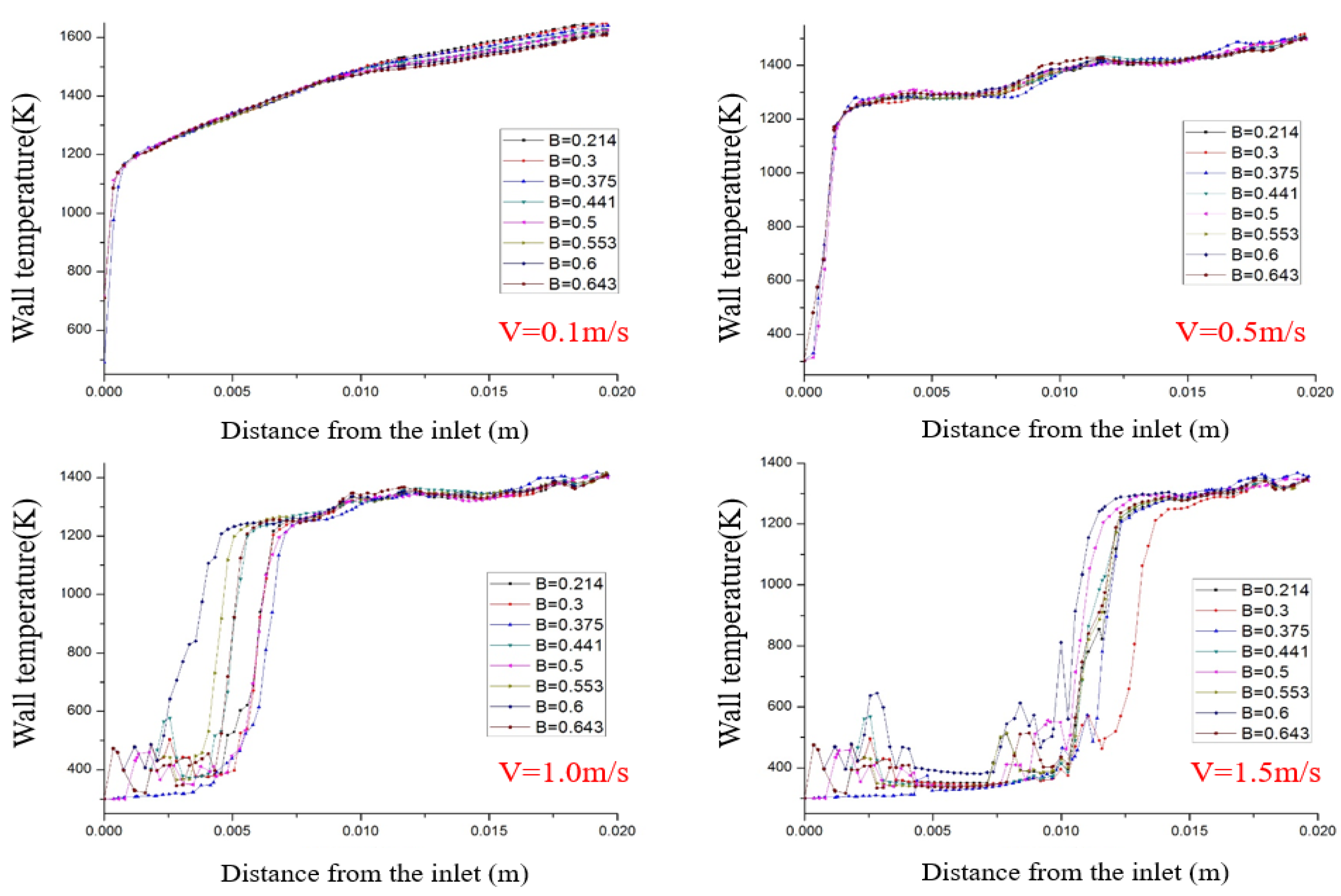
Figure 8 shows the temperature distribution along the axis of the upper wall under different slot width ratios. At the same inlet velocity, the right different slots ratio micro- combustors maintain similar wall temperature distribution trends. When the inlet velocity of premixed gas is 0.1 m/s and 0.5 m/s, the wall temperature in front of the blunt body has reached more than 1200 K and remains near the outlet and there is a relatively large high-temperature zone on the wall, the axial wall temperature distribution with different slot width ratio has a high coincidence degree. This indicates that the slot width has a slight effect on the wall temperature distribution at a lower inlet velocity, but it is worth noting that when the inlet velocity increases to 0.1 m/s, the wall temperature distribution along the axis at the first part of the combustor is almost a monotonous rising, and the rear part tends to be flat. When the inlet velocity further increases to 0.5 m/s, the wall temperature presents a wavy fluctuation along the axial direction.
The inlet velocity of premixed gas is controlled at 1.0 m/s and V =1.5 m/s. At this time, due to the high flow rate, the high-temperature zone starts from the rear part of the blunt body, and the wall temperature in front of the blunt body is mainly the premixed low-temperature gas with premixed gas. Under the condition of high velocity, the axial wall temperature of different slot width ratio is greatly different. With the increase of the inlet velocity, the position where the wall temperature increases sharply will move to the rear part of the combustor, and the length of the high-temperature zone on the wall corresponding to different slot width ratios is also different. For example, the slot width ratio B = 0.553 and B = 0.6 maintained a long high-temperature zone at the inlet velocity of 1.0 m/s. However, when the inlet velocity is increased to 1.5 m/s, although B = 0.5 and B = 0.6 still have a long high-temperature segment, the high-temperature zone corresponding to B = 0.3 is significantly shortened, and the high-temperature zone corresponding to other slot width ratios is roughly the same.
The interesting finding is that except for the micro-combustors corresponding to B = 0.375, in other bluff body combustors with too large or too small slot width, the wall temperature near the bluff body has obvious temperature fluctuation along the axis direction, and this uneven wall temperature distribution phenomenon is detrimental to the working performance of the combustor. The reason may be related to the different velocity fields caused by different slot width ratios; when the slot width ratio is too small, the near wall surface of the blunt body produces a large, premixed gas velocity, resulting in a relatively high concentration of fuel, causing a high chemical reaction rate to occur, which leads to the ignition and combustion of fuel near the catalytic surface. However, excessive inlet velocity will aggravate the heat transfer between the wall and the premixed gas, and the premixed gas will be quickly blown to the rear of the bluff body; the flame will be blown out before it is stabilized. This will directly lead to the stable reaction region only in the small local region of the catalytic surface, so the fluctuation of the wall temperature near the blunt body is formed. When the slot width ratio is too large, the fuel concentration near the wall is also maintained at a relatively low level due to the low flow rate of premixed gas around the bluff body, which further reduces the chemical reaction rate of methane. However, the lower inlet velocity weakens the convective heat transfer between the premixed gas and the inner wall, leading to heat accumulation on the wall surface and higher wall temperature, which catalyzes the combustion reaction of methane on the surface. This will also cause the reaction to occur in a local area of the catalytic surface, resulting in temperature fluctuations.
4. Conclusions
The bluff body structure has good combustion stability in the field of combustion, and different bluff body structures have a significant impact on the combustion process. In order to study the difference between the hollow hemisphere bluff body before and after slotting, the thermal performance under different air inlet speeds and slot widths was studied. The relevant conclusions are as follows:
- The jet flow in a slotted bluff body not only disturbs the velocity field and temperature field behind the blunt body but also promotes the preheating and combustion of low-temperature gas. With the inlet velocity increasing, the methane conversion efficiency of the slotted bluff body combustor increases first and then decreases, but it is also higher than that of the MCEHB at the same velocity.
- Too large or too small slot size of bluff body is not conducive to methane combustion near the wall. A slot that is too small to bring significant disturbance to the fluid behind blunt body, but too large of a slot can increase the mixing gas volume at low temperature and decrease the mixing velocity, which also provides a slight effect. Setting the slot width ratio B to 0.553 can bring the maximum jet velocity, resulting in the strongest flow field disturbance behind the bluff body.
- Methane conversion is affected by inlet velocity and slot width. With the increase of slot width ratio B, methane conversion firstly increases and then decreases. The slot width ratio corresponding to the peak is less than 0.5. Since the inlet velocity is lower than 0.5 m/s, the optimal slot width ratio B is in the range of 0.3–0.375. However, as the inlet velocity exceeds 0.5 m/s, the optimal slot width ratio B moves to the range of 0.375–0.553.
- With too large or too small slot width, the wall temperature near the bluff body fluctuates obviously along the axis direction, and this uneven wall temperature distribution is detrimental to the performance; thus, it is a reasonable choice to set the slot width ratio B at 0.375.
Author Contributions
Formal analysis, Y.C.; Methodology, Y.Y.; Writing—original draft, Y.L.; Writing—review & editing, C.Z. All authors have read and agreed to the published version of the manuscript.
Funding
The authors gratefully acknowledge financial support from the Graduate Scientific Research and Innovation Foundation of Chongqing (CYB19061).
Institutional Review Board Statement
Not applicable.
Informed Consent Statement
Not applicable.
Data Availability Statement
We did not report any data.
Conflicts of Interest
The funders had no role in the design of the study; in the collection, analyses, or interpretation of data; in the writing of the manuscript, or in the decision to publish the results.
References
- Qian, P.; Liu, M. Influencing factors of wall temperature and flame stability of micro-combustors in micro-thermophotovoltaic and micro-thermoelectric systems. Fuel 2022, 310, 122436. [Google Scholar] [CrossRef]
- Zhou, J.; Wang, Y.; Yang, W.; Liu, J.; Wang, Z.; Cen, K. Combustion of hydrogen–air in catalytic micro-combustors made of different material. Int. J. Hydrogen Energy 2009, 34, 3535–3545. [Google Scholar] [CrossRef]
- Wan, J.; Fan, A. Recent progress in flame stabilization technologies for combustion-based micro energy and power systems. Fuel 2021, 286, 119391. [Google Scholar] [CrossRef]
- E, J.; Ding, J.; Chen, J.; Liao, G.; Zhang, F.; Luo, B. Process in micro-combustion and energy conversion of micro power system: A review. Energy Convers. Manag. 2021, 246, 114664. [Google Scholar] [CrossRef]
- Chang, J.; Zhang, J.; Bao, W.; Yu, D. Research progress on strut-equipped supersonic combustors for scramjet application. Prog. Aerosp. Sci. 2018, 103, 1–30. [Google Scholar] [CrossRef]
- Huang, W.; Du, Z.-b.; Yan, L.; Moradi, R. Flame propagation and stabilization in dual-mode scramjet combustors: A survey. Prog. Aerosp. Sci. 2018, 101, 13–30. [Google Scholar] [CrossRef]
- Chanphavong, L.; Zainal, Z.A. Characterization and challenge of development of producer gas fuel combustor: A review. J. Energy Inst. 2019, 92, 1577–1590. [Google Scholar] [CrossRef]
- Shirsat, V.; Gupta, A.K. A review of progress in heat recirculating meso-scale combustors. Appl. Energy 2011, 88, 4294–4309. [Google Scholar] [CrossRef]
- Anand, V.; Gutmark, E. Rotating detonation combustors and their similarities to rocket instabilities. Prog. Energy Combust. Sci. 2019, 73, 182–234. [Google Scholar] [CrossRef] [Green Version]
- Chia, L.C.; Feng, B. The development of a micropower (micro-thermophotovoltaic) device. J. Power Sources 2007, 165, 455–480. [Google Scholar] [CrossRef]
- Ruan, C.; Chen, F.; Cai, W.; Qian, Y.; Yu, L.; Lu, X. Principles of non-intrusive diagnostic techniques and their applications for fundamental studies of combustion instabilities in gas turbine combustors: A brief review. Aerosp. Sci. Technol. 2019, 84, 585–603. [Google Scholar] [CrossRef]
- Xue, Z.; Yan, Y.; He, Z.; Shen, K.; Zhang, C. Comprehensive numerical insight the thermal performance improvement of the micro combustors with internal bionic Y-shaped fins for micro-thermal voltaic system applications. Fuel 2022, 318, 123610. [Google Scholar] [CrossRef]
- Ni, S.; Zhao, D.; Zhu, X. Heat transfer and entropy production evaluation on premixed hydrogen/air-fuelled micro-combustors with internal threads. Fuel 2021, 303, 131325. [Google Scholar] [CrossRef]
- Gao, W.; Yan, Y.; Shen, K.; Huang, L.; Zhao, T.; Gao, B. Combustion characteristic of premixed H2/air in the micro cavity combustor with guide vanes. Energy 2022, 239, 121975. [Google Scholar] [CrossRef]
- Mohseni, S.; Nadimi, E.; Jafarmadar, S.; Rezaei, R.A. Enhance the energy and exergy performance of hydrogen combustion by improving the micro-combustor outlet in thermofluidic systems. Int. J. Hydrogen Energy 2021, 46, 6915–6927. [Google Scholar] [CrossRef]
- Jiaqiang, E.; Cai, L.; Li, J.; Ding, J.; Chen, J.; Luo, B. Effects analysis on the catalytic combustion and heat transfer performance enhancement of a non-premixed hydrogen/air micro combustor. Fuel 2022, 309, 122125. [Google Scholar] [CrossRef]
- Li, L.; Yang, G.; Fan, A. Non-premixed combustion characteristics and thermal performance of a catalytic combustor for micro-thermophotovoltaic systems. Energy 2021, 214, 118893. [Google Scholar] [CrossRef]
- Yan, Y.; Wu, G.; Huang, W.; Zhang, L.; Li, L.; Yang, Z. Numerical comparison study of methane catalytic combustion characteristic between newly proposed opposed counter-flow micro-combustor and the conventional ones. Energy 2019, 170, 403–410. [Google Scholar] [CrossRef]
- Lu, Q.; Gou, J.; Pan, J.; Zhang, Y.; Zhu, J.; Quaye, E.K. Comparison of the effect of heat release and products from heterogeneous reaction on homogeneous combustion of H2/O2 mixture in the catalytic micro combustor. Int. J. Hydrogen Energy 2019, 44, 31557–31566. [Google Scholar] [CrossRef]
- Chen, J.; Song, W.; Gao, X.; Xu, D. Hetero-/homogeneous combustion and flame stability of fuel-lean propane–air mixtures over platinum in catalytic micro-combustors. Appl. Therm. Eng. 2016, 100, 932–943. [Google Scholar] [CrossRef]
- Wu, Y.; Peng, Q.; Yang, M.; Shan, J.; Yang, W. Entropy generation analysis of premixed hydrogen–air combustion in a micro combustor with porous medium. Chem. Eng. Processing-Process Intensif. 2021, 168, 108566. [Google Scholar] [CrossRef]
- Ni, S.; Zhao, D.; Cai, T.; Cao, F. Energy conversion efficiency improvement studies on unconventional premixed micro-combustors partially inserted with porous medium. Fuel Process. Technol. 2021, 215, 106774. [Google Scholar] [CrossRef]
- Li, Q.; Li, J.; Shi, J.; Guo, Z. Effects of heat transfer on flame stability limits in a planar micro-combustor partially filled with porous medium. Proc. Combust. Inst. 2019, 37, 5645. [Google Scholar] [CrossRef]
- Wei, J.; Fu, G.; Yang, W.; Li, S.; E, J.; Peng, Q.; Zhang, A. Investigation on hydrogen-fueled combustion characteristics and thermal performance in a micro heat-recirculation combustor inserted with block. Int. J. Hydrogen Energy 2021, 46, 36515–36527. [Google Scholar] [CrossRef]
- He, Z.; Yan, Y.; Feng, S.; Li, X.; Yang, Z.; Ran, J.; Gan, Y. Investigation on premixed methane/air combustion characteristics in heat recirculation micro combustor with separating cylinder. Chem. Eng. Process.-Process Intensif. 2020, 153, 107987. [Google Scholar] [CrossRef]
- Tang, A.; Cai, T.; Deng, J.; Xu, Y.; Pan, J. Experimental investigation on combustion characteristics of premixed propane/air in a micro-planar heat recirculation combustor. Energy Convers. Manag. 2017, 152, 65–71. [Google Scholar] [CrossRef]
- Pan, J.; Zhang, C.; Pan, Z.; Wu, D.; Zhu, Y.; Lu, Q.; Zhang, Y. Investigation on the effect of bluff body ball on the combustion characteristics for methane/oxygen in micro combustor. Energy 2020, 190, 116465. [Google Scholar] [CrossRef]
- Yan, Y.; Yan, H.; Zhang, L.; Li, L.; Zhu, J.; Zhang, Z. Numerical investigation on combustion characteristics of methane/air in a micro-combustor with a regular triangular pyramid bluff body. Int. J. Hydrogen Energy 2018, 43, 7581–7590. [Google Scholar] [CrossRef]
- Wang, M.; Li, P.; Wang, F. Dependence of the blowout limit on flow structure, heat transfer, and pressure loss in a bluff-body micro-combustor. Int. J. Hydrogen Energy 2020, 45, 19912–19925. [Google Scholar] [CrossRef]
- Fan, A.; Wan, J.; Liu, Y.; Pi, B.; Yao, H.; Liu, W. Effect of bluff body shape on the blow-off limit of hydrogen/air flame in a planar micro-combustor. Appl. Therm. Eng. 2014, 62, 13–19. [Google Scholar] [CrossRef]
- Zhang, L.; Zhu, J.; Yan, Y.; Guo, H.; Yang, Z. Numerical investigation on the combustion characteristics of methane/air in a micro-combustor with a hollow hemispherical bluff body. Energy Convers. Manag. 2015, 94, 293–299. [Google Scholar] [CrossRef]
- Yan, Y.; Liu, Y.; Li, L.; Cui, Y.; Zhang, L.; Yang, Z.; Zhang, Z. Numerical comparison of H2/air catalytic combustion characteristic of micro–combustors with a conventional, slotted or controllable slotted bluff body. Energy 2019, 189, 6901–6914. [Google Scholar] [CrossRef]
- Yan, Y.; Xu, F.; Xu, Q.; Zhang, L.; Yang, Z.; Ran, J. Influence of controllable slot width and angle of controllable flow on hydrogen/air premixed combustion characteristics in micro combustor with both sides–slotted bluff body. Int. J. Hydrogen Energy 2019, 44, 20482–20492. [Google Scholar] [CrossRef]
- Gao, W.; Yan, Y.; Huang, L.; Shen, K.; He, Z.; Gao, B. Numerical comparison of premixed H2/air combustion characteristic of three types of micro cavity-combustors with guide vanes, bluff body, guide vanes and bluff body respectively. Int. J. Hydrogen Energy 2021, 46, 24382–24394. [Google Scholar] [CrossRef]
- Xu, F.; Yan, Y.; He, Z.; Yang, Z.; Zhang, L. Numerical study on the influence of controllable flow ratio on combustion characteristics of a controllable central slotted bluff body and cavity combined micro combustor. Int. J. Hydrogen Energy 2021, 46, 6901–6914. [Google Scholar] [CrossRef]
- He, Z.; Yan, Y.; Fang, R.; Ou, Z.; Zhang, Z.; Yang, Z.; Zhang, Z. Numerical investigation of a novel micro combustor with a central and bilateral slotted blunt body. Int. J. Hydrogen Energy 2021, 46, 23564–23579. [Google Scholar] [CrossRef]
- Li, L.; Fan, A. A numerical study on non-premixed H2/air flame stability in a micro-combustor with a slotted bluff-body. Int. J. Hydrogen Energy 2021, 46, 2658–2666. [Google Scholar] [CrossRef]
- Deutschmann, O.; Maier, L.I.; Riedel, U.; Stroemman, A.H.; Dibble, R.W. Hydrogen assisted catalytic combustion of methane on platinum. Catal. Today 2000, 59, 141–150. [Google Scholar] [CrossRef]
- Leach, T.T.; Cadou, C.P. The role of structural heat exchange and heat loss in the design of efficient silicon micro-combustors. Proc. Combust. Inst. 2005, 30, 2437–2444. [Google Scholar] [CrossRef]
- Jiang, D.; Yang, W.; Chua, K.J.; Ouyang, J. Thermal performance of micro-combustors with baffles for thermophotovoltaic system. Appl. Therm. Eng. 2013, 61, 670–677. [Google Scholar] [CrossRef]
- Yan, Y.; Pan, W.; Zhang, L.; Tang, W.; Chen, Y.; Li, L. Numerical study of the geometrical parameters on CH4/air premixed combustion in heat recirculation micro-combustor. Fuel 2015, 159, 45–51. [Google Scholar] [CrossRef]
Figure 1.
Physical model.

Figure 2.
Grid independence verification.

Figure 3.
Velocity field distribution of two combustors.

Figure 4.
Temperature field distribution in different combustors.
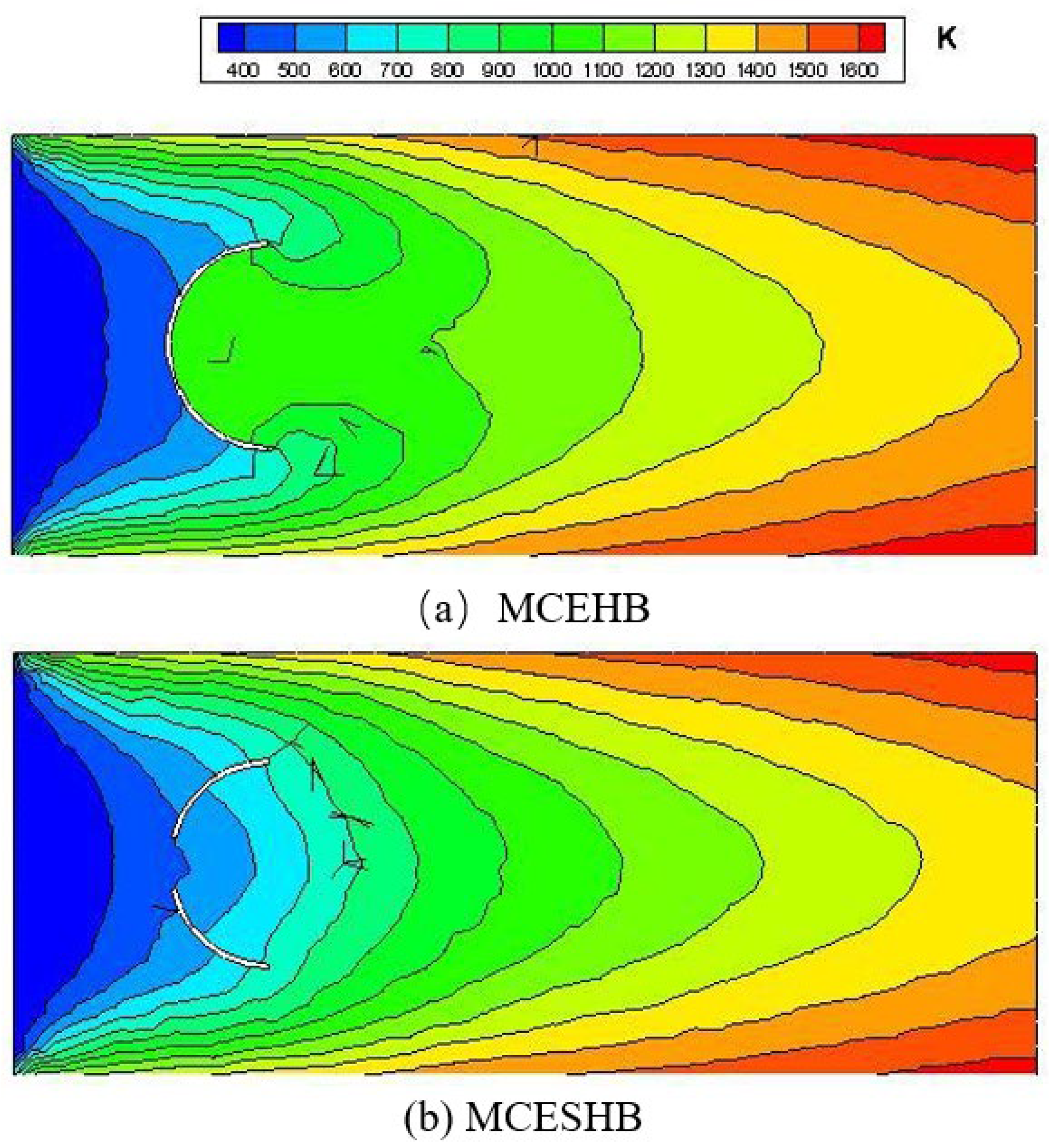
Figure 5.
Effect of inlet velocity on methane conversion.

Figure 6.
(a–h) Velocity field at different slot width ratios (v = 1.0 m/s).
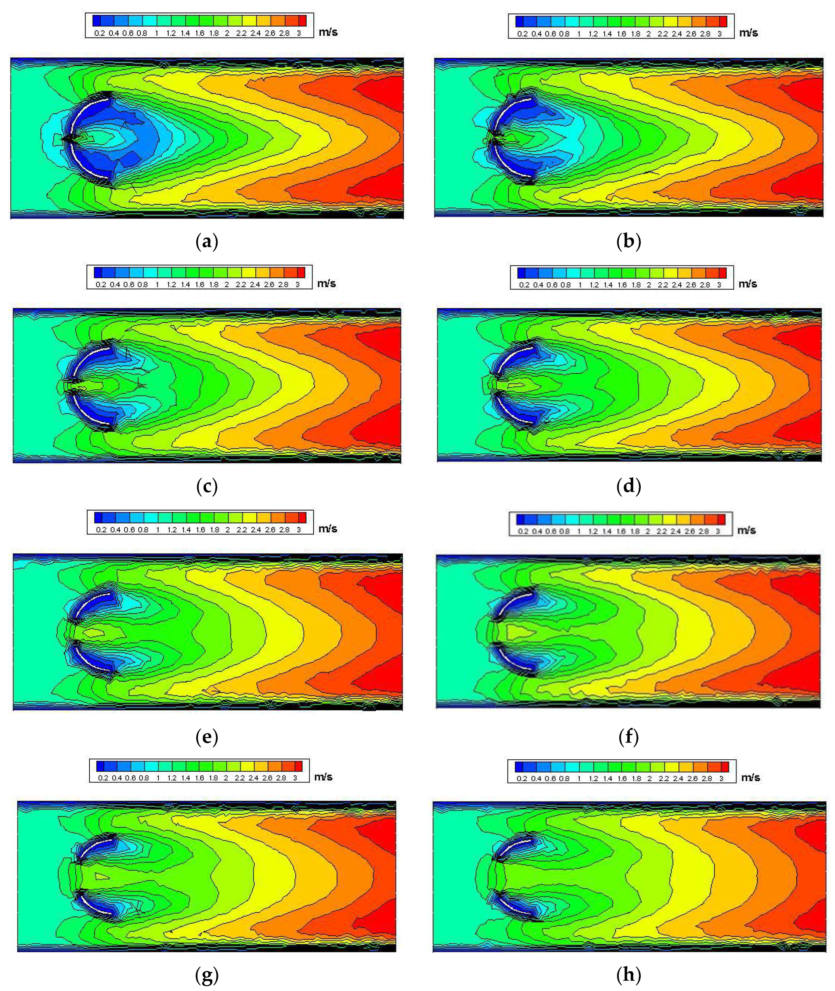
Figure 7.
Effect of slot width ratio at different velocities on methane conversion.

Figure 8.
The axial wall temperature at different velocities.

Table 1.
The 24-step surface reaction mechanism of methane [38].
Table 1.
The 24-step surface reaction mechanism of methane [38].
| Order | Elementary | A/[(cm3/mol)n−1/s] | B | E/(kJ/mol) |
|---|---|---|---|---|
| 1 | H2 + Pt(s) + Pt(s) ⇒ H(s) + H(s) | 4.60 × 10⁻² | 0.0 | 0.0 |
| 2 | H(s) + H(s) ⇒ Pt(s) + Pt(s) + H2 | 3.70 × 10²¹ | 0.0 | 67.4 |
| 3 | H + Pt(s) ⇒ H(s) | 1.0 | 1.0 | 0.0 |
| 4 | O2 + Pt(s) + Pt(s) ⇒ O(s) + O(s) | 1.80 × 10²¹ | −0.5 | 0.0 |
| 5 | O2 + Pt(s) + Pt(s) ⇒ O(s) + O(s) | 2.30 × 10⁻² | 0.0 | 0.0 |
| 6 | O(s) + O(s) ⇒ Pt(s) + Pt(s) + O2 | 3.70 × 10²¹ | 0.0 | 213.2 |
| 7 | O + Pt(s) ⇒ O(s) | 1.0 | 1.0 | 0.0 |
| 8 | H2O + Pt(s) ⇒ H2O(s) | 0.75 | 0.0 | 0.0 |
| 9 | H2O(s) ⇒ H2O + Pt(s) | 1.00 × 10¹³ | 0.0 | 40.3 |
| 10 | OH+ Pt(s) ⇒ OH(s) | 1.0 | 0.0 | 0.0 |
| 11 | OH(s) + Pt(s) ⇒ OH | 1.00 × 10¹³ | 0.0 | 192.8 |
| 12 | O(s) + H(s) ⇒ Pt(s) + OH(s) | 3.70 × 10²¹ | 0.0 | 11.5 |
| 13 | H(s) + OH(s) ⇒ H2O(s) + Pt(s) | 3.70 × 10²¹ | 0.0 | 17.4 |
| 14 | OH(s) + OH(s) ⇒ H2O(s) + O(s) | 3.70 × 10²¹ | 0.0 | 48.2 |
| 15 | CO + Pt(s) ⇒ CO(s) | 8.40 × 10⁻¹ | 0.5 | 0.0 |
| 16 | CO(s) ⇒ CO + Pt(s) | 1.00 × 10¹³ | 0.0 | 125.5 |
| 17 | CO2(s) ⇒ CO2 + Pt(s) | 1.00 × 10¹³ | 0.0 | 20.5 |
| 18 | CO(s) + O(s) ⇒ CO2(s) + Pt(s) | 3.70 × 10²¹ | 0.0 | 105.0 |
| 19 | CH4(s) + Pt(s) + Pt(s) ⇒ CH3(s) + H(s) | 1.00 × 10⁻² | 0.5 | 0.0 |
| 20 | CH3(s) + Pt(s) ⇒ CH2(s) + H(s) | 3.70 × 10²¹ | 0.0 | 20.0 |
| 21 | CH2(s) + Pt(s) ⇒ CH(s) + H(s) | 3.70 × 10²¹ | 0.0 | 20.0 |
| 22 | CH(s) + Pt(s) ⇒ C(s) + H(s) | 3.70 × 10²¹ | 0.0 | 20.0 |
| 23 | C(s) + O(s) ⇒ CO(s) + Pt(s) | 3.70 × 10²¹ | 0.0 | 62.8 |
| 21 | CO(s) + Pt(s) ⇒ C(s) + O(s) | 1.00 × 10¹⁸ | 0.0 | 184.0 |
Table 2.
Model-related parameter settings.
| Boundary | Parameter | Value |
|---|---|---|
| Inlet (Velocity inlet) | Temperature | 300 K |
| Gauge pressure | 0 | |
| Outlet (pressure outlet) | Slip | No-slip |
| Fluid-Solid Surface |
Table 3.
Structure parameter of micro-combustors with different slot width ratios.
| Serial Numbers | Slot Height (mm) | Slot Width Ratio |
|---|---|---|
| 1 | 0.5 | 0.214 |
| 2 | 0.75 | 0.300 |
| 3 | 1.0 | 0.375 |
| 4 | 1.25 | 0.441 |
| 5 | 1.5 | 0.500 |
| 6 | 1.75 | 0.553 |
| 7 | 2.0 | 0.600 |
| 8 | 2.25 | 0.643 |
Publisher’s Note: MDPI stays neutral with regard to jurisdictional claims in published maps and institutional affiliations. |
© 2022 by the authors. Licensee MDPI, Basel, Switzerland. This article is an open access article distributed under the terms and conditions of the Creative Commons Attribution (CC BY) license (https://creativecommons.org/licenses/by/4.0/).
Share and Cite
MDPI and ACS Style
Liao, Y.; Zhang, C.; Chen, Y.; Yan, Y. Combustion Performance of Methane/Air in a Micro Combustor Embedded Hollow Hemispherical Slotted Bluff Body. Energies 2022, 15, 4033. https://doi.org/10.3390/en15114033
AMA Style
Liao Y, Zhang C, Chen Y, Yan Y. Combustion Performance of Methane/Air in a Micro Combustor Embedded Hollow Hemispherical Slotted Bluff Body. Energies. 2022; 15(11):4033. https://doi.org/10.3390/en15114033
Chicago/Turabian StyleLiao, Yunzhe, Chenghua Zhang, Yanrong Chen, and Yunfei Yan. 2022. "Combustion Performance of Methane/Air in a Micro Combustor Embedded Hollow Hemispherical Slotted Bluff Body" Energies 15, no. 11: 4033. https://doi.org/10.3390/en15114033
Note that from the first issue of 2016, this journal uses article numbers instead of page numbers. See further details here.