
Study of Key Technology of Gob-Side Entry Retention in a High Gas Outburst Coal Seam in the Karst Mountain Area


1
School of Mining, Guizhou University, Guiyang 550025, China
2
Guizhou Panjiang Coal and Electricity Group Technology Research Institute Co., Ltd., Guiyang 550081, China
3
Guizhou Qianxi Honglin Mining Co., Ltd., Bijie 551500, China
*
Author to whom correspondence should be addressed.
Energies 2022, 15(11), 4161; https://doi.org/10.3390/en15114161
Submission received: 11 April 2022
/
Revised: 13 May 2022
/
Accepted: 13 May 2022
/
Published: 6 June 2022
(This article belongs to the Topic Mining Safety and Sustainability)
Abstract
:In the gob-side entry retaining by roof cutting (GERRC) technique, pressure is offloaded via directional roof cutting, and a roadway is automatically formed due to the ground pressure and rock-breaking expansion. To improve the application of the theory and technical system of GERRC in the Karst area in Southwest China, this research studies the key technology of GERRC in a high gas outburst coal seam, based on the engineering background of the 39114 working face of the Honglin coal mine. According to the geological conditions of the 39114 working face, by means of formula calculation, UDEC numerical modeling, and on-site drilling peeping, the optimal roof-cutting parameters suitable for the 39114 working face were determined: the roof cutting height was 7 m, the roof cutting angle was 15°, and the spacing of pre-splitting blasting holes was 600 mm. Additionally, the above roof-cutting parameters have achieved good results in the engineering practices of the 39114 transportation roadway, which shows that the technology of GERRC is feasible in high gas outburst mines and achieves the goal of safe and efficient mining.
1. Introduction
As the world’s largest energy production and consumption country, coal occupies the main position in China’s energy consumption structure. With the depletion of easy-to-mine coal resources, gob-side entry retaining technology has become the primary research and application direction of coal-efficient mining because of its advantages of maximizing resource recovery, avoiding coal loss, and reducing roadway excavation. Since its application in China in the 1970s, gob-side entry retaining (GER) technology has made outstanding contributions to the field of non-pillar mining [1,2,3].
On the basis of gob-side entry retaining technology (GER), He Manchao’s team proposed the technology of gob-side entry retaining by roof cutting (GERRC). In gob-side entry retaining, the crushing and expansion characteristics of caving waste rock are used to allow waste rock to fill the mined-out areas and form roadway sides, and further cancel the filling body [4,5,6,7]. Because of its advantages of low cost, easy operation, and fast lane keeping, this technology has been tested and popularized under different geological and mining conditions, such as different coal thickness [8,9,10], different buried depth [11,12], and different roof conditions [13,14], and produced great economic and social benefits. On this basis, domestic and foreign scholars have conducted in-depth research on GERRC.
Scholars in various countries have carried out in-depth research on GERRC. For example, Wang Q [14] performed a field engineering test in the Ningtiaota mining field, and proved the feasibility both of no coal-pillar mining schemes, and the technology of automatically forming gob-side entry retention by roof cutting and pressure relief. He M [15] used mechanical analysis and numerical simulation to analyze the structural characteristics of composite roofs and the effect of GERRC under composite roofs. Shao L [16] studied the pressure-relief law of secondary gob-side entry retention after double-side roof cutting in a thin coal seam, which provides an important reference value for secondary gob-side entry retention in the future. Zhu Z [17] used numerical simulation to analyze key problems, such as abutment pressure and stress concentration shells, and study the distribution and evolution characteristics of macroscopic stress fields of surrounding rocks in GERRC, and the differences from traditional pillar-retaining mining methods. Ma X [18] studied the design of GERRC by means of mechanical analysis, geometric analysis, and numerical simulation. Chen T [19] established a mechanical model of hard roofs, and analyzed the process of pressure relief by roof cutting; the key stage of roadway-stability control in the process of pressure relief by roof cutting was determined. Based on key block theory, Sun B [20] established the mechanical model of basic roof fracture structures, and the roof fracture mechanism of gob-side entry retention under the conditions of roof cutting and pressure relief was studied.
In addition, high gas mines are widely distributed in China and around the world [21,22,23]. To explore the applicability of the GERRC technology to high gas mines, the haulage roadway of the 39114 working face in the Honglin Coal Mine of Guizhou Province was taken as the research background. The key technology and advanced influence range of GERRC and pressure relief in gas outburst mines were studied by means of theoretical analysis, numerical simulation, and field tests. The research results have certain significance for improving the theory and technology systems of GERRC.
2. Engineering Survey
Honglin Coal Mine is located in Qianxi City, Guizhou province, China. The 9# and 15# coal seams are mainly mined in the Honglin Coal Mine. The 9# coal seam is unstable, with a thickness of 1.08–3.67 m, and the average thickness is 2.21 m.
The 39114 working face mainly mines the 9# coal seam, and the 9# coal seam is located in the weak aquifer in the middle of the Longtan formation. The upper limestone aquifer of the Changxing formation is about 60 m, and the lower is about 65 m from the strong aquifer of the Maokou formation. The water insulation of the coal seam is good, where only a small amount of bedrock fissure water is contained, and there is no water-conducting fault in the area.
The immediate roof of the coal seam is argillaceous siltstone, with a thickness of 3.0–4.5 m, and the average thickness is 3.38 m. The main roof is fine-grained sandstone with a thickness of 5.3–7.6, and the average thickness is 6.97 m. The main floor is argillaceous siltstone with a thickness of 6.72 m. The column diagram of the roof and floor lithology is shown in Figure 1.
The 39114 haulage roadway is a rectangular section with a width of 4.5 m and a height of 2.8 m. The original support section is as shown in Figure 2.
3. Gas Prevention and Control Measures
The 9# coal seam belongs to a high gas outburst coal seam; the gas content at the elevation of +1435 m to +1540 m is 13.9374 m3/t, the gas pressure is 0.8 MPa, and the firmness is 1.3. To ensure the safe and efficient production of the mine, it is necessary to take corresponding gas outburst prevention measures during the excavation and mining of the 39114 working face. Therefore, the method of mining the liberated seam was adopted as the regional outburst prevention measure during the roadway excavation of the 39114 working face. During the mining of the working face, pre-draining coal seam gas was used as the regional outburst prevention measure.
3.1. Mining the Liberated Seam
When the liberated seam is mined, the roof or floor of the protective coal seams can be damaged and cracks can develop. At the same time, the gas in the protective coal seams changes from an adsorption state to a free state under the influence of mining. This free gas moves to the liberated seam through the cracks, so as to achieve the effect of treating the protective coal seam gas [24].
The 39114 working face is situated in the 9# coal seam, which is adjacent to the 7# and 15# coal seams. The average interval between the 7# coal seam and the 9# coal seam is 11 m, the average interval between the 15# coal seam and the 9# coal seam is 55 m, and the positional relationship between the three coal seams is shown in Figure 3. The original gas content and pressure of the 7#, 9#, 15# coal seams are shown in Table 1. According to the above data, the threat of gas disaster in the 15# coal seam is relatively small, so the 15# coal seam was selected as the liberated seam, and the 9# coal seam was selected as the protective seam.
Before mining the 15# coal seam, the pre-drainage of gas per 80 m roadway could reach the standard level for about 25 days during the excavation of roadways in the 39114 working face. The single-hole gas pre-drainage concentration was about 8–36%, and the average excavation length per month was 30–50 m.
After mining the 15# coal seam, within the protection range of the liberated seam, the pre-drainage of gas per 80 m roadway was about 15 days, which was about 40% shorter than it was before mining the liberated seam. The single hole extraction concentration was 15–48%, and the average excavation length per month could be increased to 90 m.
To further verify the gas prevention and control effect of the liberated seam, 6 inspection holes and 18 inspection points were arranged in the 39114 haulage roadway. The maximum gas content was 6.831 m3/t, with an average of 6.13 m3/t, which was 55.9% lower than the original average gas content of the 9# coal seam, and the protected range as shown in Figure 3.
The monitoring results show that mining the 15# coal seam as the liberated seam has a better gas-control effect on the 9# coal seam.
3.2. Gas Pre-Drainage
After the excavation of the 39114 mining roadway was completed, in order to ensure the safe and efficient advancement of the working face, pre-drainage boreholes needed to be arranged in the 9# coal seam. In addition, the overlying coal seam of the 9# coal seam is the 7# coal seam, and the distance between the two coal seams is only 11 m. Therefore, when arranging gas pre-drainage boreholes in the 9# coal seam, the gas pre-drainage boreholes of the 7# coal seam also needed to be arranged.
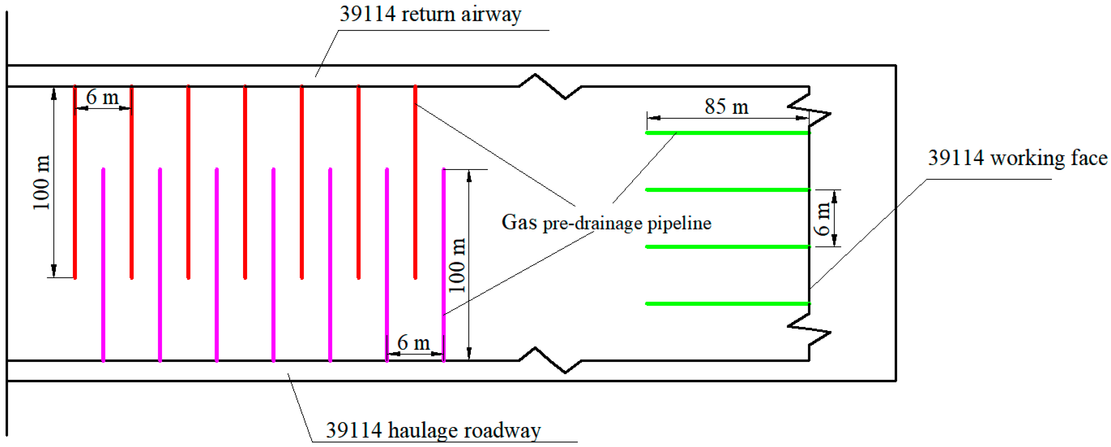
After the gas pre-drainage method was determined, the gas in the 9# coal seam was pre-extracted by drilling along the seam in the 39114 return airway, the 39114 haulage roadway, and the setup entry, as shown in Figure 4. The drilling parameters of gas pre-drainage through the 7# coal seam are shown in Table 2.
3.3. Evaluation of Gas Pre-Drainage Effect
In order to verify the gas pre-drainage effect of the 9# coal seam, the gas pre-drainage rate and residual gas content were analyzed in the range of 300 m outward from the setup entry of the 39114 working face. In this area, there were a total of 146 horizontal boreholes and 168 through-layer boreholes.
3.3.1. Gas Pre-Drainage Rate
According to the estimation formula of the total amount of gas in the original coal seam:
In this formula, Qo is the original coal seam gas volume in the gas pre-drainage borehole control area, unit: m3; S is the area of borehole control range, unit: m2; q is the original gas content, unit: m3/t; h is the thickness of the coal seam, unit: m; γ is the bulk density of the coal seam, unit: t/m3.
After calculation, the original gas volume of the 9# coal seam Qo9 was 2.3733 million m3, and the original gas volume of the 7# coal seamQo7 was 0.2533 million m3.
Because the residual gas content after pre-drainage should be lower than 8 m3/t, the calculation formula of minimum gas pre-drainage amount can be obtained:
In this formula, Qmin is the minimum gas pre-drainage volume, unit: m3; T is the total coal weight within the control range of the borehole, unit: t. It is calculated that the minimum gas pre-drainage volume from the 7# and 9# coal seams was 1.1017 million m3. Thus, the minimum gas pre-drainage rate is 1.1017/(0.2533 + 2.3733) = 41.94%.
In order to detect the gas pre-drainage effect, the GD3 pipeline automatic metering system and the manual CZJ-70 gas comprehensive parameter tester were used to monitor the gas pre-drainage data in the 39114 working face. The total gas pre-drainage volume of the GD3 pipeline automatic metering system is 1.1653 million m3; therefore, the gas pre-drainage rate is 1.1653/(0.2533 + 2.3733) = 44.37%. According to the statistics of the measured data of each of the pre-drainage boreholes by the CZJ-70 gas comprehensive parameter tester, the total gas pre-drainage volume is 1.1842 million m3; therefore, the gas pre-drainage rate is 1.1842/(0.2533 + 2.3733) = 45.10%. The above two gas pre-drainage rates are greater than the minimum gas pre-drainage rate, which is 41.94%, indicating that the pre-drainage effect is remarkable, achieving the purpose of gas outburst elimination.
3.3.2. Residual Gas Content and Residual Gas Pressure
To further verify the accuracy of the gas outburst elimination effect in the 39114 working face, 6 boreholes in the 9# coal seam were respectively arranged in the 39114 return airway and haulage roadway, and the residual gas pressure and residual gas content were measured. In addition, 4 boreholes through the 7# coal seam were respectively arranged in the 39114 return airway and haulage roadway to determine the residual gas pressure and residual gas content of the 7# coal seam. The parameters of the boreholes after on-site measurement and calculation are shown in Table 3.
The residual gas content in all of the boreholes measured above was less than 8 m3/t. The residual gas pressure was less than 0.74 MPa, which meets the requirements of coal-seam outburst elimination. To further evaluate the outburst elimination effect, 12 boreholes which measured 42 mm in diameter and 10 m in depth were constructed in the 39114 working face, and the WTC-2 gas outburst parameter instrument was used to verify the gas desorption index of the drilling (K1) and drilling cuttings weight (S). After measurement, the maximum value of K1 was 0.23, and the maximum value of S was 1.8, which are all less than the critical index (K1 < 0.50, S < 6.0). Therefore, the above two measurement results show that the outburst elimination effect of the 39114 working face is noteworthy, which created good conditions for the implementation of gob-side entry retention.
4. Determination of Key Technology of Roof Cutting
4.1. Numerical Simulation
As shown in Figure 5, α refers to the cutting angle between the roof cutting line and the plumb line. H is the roof cutting height, which refers to the maximum vertical height of the roof cutting seam.
To determine the reasonable roof cutting height and angle, the UDEC numerical simulation model was established according to the engineering geological conditions of the 39114 working face. The model was 100 m long and 70 m high, and fixed constraints were imposed on the left, right, and bottom boundaries. A vertical load of 4.0 MPa was applied to the top of the model to simulate the 160 m thick overlying strata. Subsequently, the numerical models with different roof cutting heights and angles were established and calculated. Based on the above, the collapse morphology and vertical displacement variation of roadway-surrounding rock for different roof cutting parameters were studied.
4.1.1. Roof Cutting Height
During the simulation of roof cutting height, the roof cutting heights were 5.5 m, 7 m and 8.5 m. The other parameters remain unchanged, and the roof cutting angle was always 15°, which was biased towards the mined-out areas. The excavation method of the working face is gradual excavation, and half of the model was intercepted for analysis after calculation and balance. Collapse morphology and vertical displacement of the model for different roof cutting heights are shown in Figure 6. At the same time, the monitoring points were arranged on the roadway roof; these were used to monitor the maximum deformation of the roadway roof, and the results are shown in Figure 7.
Analysis of the collapse morphology of roadway-surrounding rock for different roof cutting height shows that roof cutting can effectively cut off the structural connection between the roof of mined-out areas and the roadway roof. The roof of the mined-out area broke and fell down along the roof cutting seam, and the roof of the roadway formed a short-arm beam structure. After the basic roof sunk, it was stable after contacting the collapsed gangue in the mined-out areas, providing bearing support for the roof of the roadway.
It can be seen from Figure 6a that when the roof cutting height is 5.5 m, the roof of mined-out areas is cut down along the roof cutting seam at the height of 5.5 m. In the process of roof cutting, there is friction between the roof of the mined-out areas and the roadway roof, which exerts a downward force on the short-arm beam structure of the roadway roof, resulting in the subsidence of the roadway roof; the maximum deformation of the roadway roof was 167 mm. In addition, there is a large unfilled space between the crushed gangue and the basic roof, as shown in Figure 6a.
When the roof cutting height is increased to 7 m, the roof of the mined-out areas is cut down along the roof cutting seam at a height of 7 m. It can be seen from Figure 6b that with the increase in roof cutting height, the roof cutting range of the mined-out area increases, and the degree to which the mined-out area is filled increases, after the collapse of rock fragmentation and expansion. Meanwhile, the deformation of the roadway roof is effectively controlled, and the maximum roadway roof deformation is 104 mm, which is smaller than that when the cutting height is 5.5 m.
As can be seen from Figure 6c, when the roof cutting height is further increased to 8.5 m, the unfilled space between the main roof and mined-out areas is further reduced. However, due to the increased roof cutting height, the force exerted on the short-arm structure of the roadway roof also increases, resulting in the greater deformation of the roadway roof, with a maximum deformation of 112 mm.
In summary, the height of roof cutting affects both the degree to which the mined-out areas are filled, and the force of the roof cutting on the short-arm structure of the roadway. A reasonable roof cutting height is needed to ensure that the expanded gangue fills the mined-out areas as much as possible and the cutting force on the roof of the roadway is as small as possible. From the numerical simulation results, it can be seen that increasing the roof cutting height within a certain range can improve the expansion volume of gangue and reduce the unfilled space of mined-out areas. However, further increases in roof cutting height may not be conducive to the stability of roadway roof, and also increase construction costs and difficulty. The numerical simulation results show that when the cutting height is 7 m, the roof cutting effect is preferable.
4.1.2. Roof Cutting Angle
A reasonable cutting angle can reduce the friction between the gob roof and the reserved roadway roof, enhance the cutting effect and controlling the roadway roof deformation. In the roof cutting angle simulation, the roof cutting angles of 0°, 10°, 15° and 20° were simulated to observe the surrounding rock collapse morphology and vertical displacement distribution characteristics of the roadway. Except for the cutting angle, the other parameters were kept unchanged, and the cutting height was 7 m. The simulation results are shown in Figure 8, and the maximum deformation of the roadway roof for different cutting angles is shown in Figure 9.
As shown in Figure 8a, when the roof cutting line is perpendicular to the roadway roof, that is, the cutting angle is 0°, the force of the roof of the mined-out areas on the short-arm beam structure of the roadway roof is significantly increased, resulting in a significant deformation of the roadway roof. The cutting seam line is perpendicular to the roof, and the crushed and expanded gangue only plays a vertical support role for the direct roof and does not play a support role for the short-arm beam structure of the roadway roof, which is also one of the direct reasons for the large deformation of the roadway. When the roof cutting angle is 0°, the maximum roadway roof deformation is 164 mm, as shown in Figure 9. As shown in Figure 8b, the friction between the roof of the mined-out areas and the roadway roof decreases after the roof cutting angle is increased to 10°. The gangue collapse is close to the short-arm beam structure of the roadway, which provides a certain support for it. Increasing the cutting angle can effectively control the roof deformation. When the cutting angle is 10°, the maximum deformation of the roadway roof is 116 mm, which is 29.3% lower than the deformation when the cutting angle is 0°, as shown in Figure 9.
When the roof cutting angle is 15°, the force between the roof of the mined-out areas and the roadway roof is further decreased, and the collapsed rock is also close to the short-arm beam structure of the roadway, providing greater support. Compared with the roof cutting angle of 10°, the maximum deformation of the roadway roof is slightly reduced to 104 mm, which is a reduction of 10.3%. As shown in Figure 8c, when the roof cutting angle continues to increase to 20°, due to the large roof cutting angle, the collapsed rock is more inclined to the mined-out areas, resulting in increased space between the collapsed rock and the short-arm structure of the roadway roof, which reduces the supporting effect of collapsed rock on the roadway roof. Therefore, it is not conducive to roadway stability, and the maximum roadway roof deformation is 137 mm.
In summary, there is an appropriate value for the roof cutting angle. When the roof cutting angle exceeds this value, continuing to increase the roof cutting angle is detrimental to the stability of the roadway. It can be seen from the numerical simulation results that when the cutting angle is ~15°, the roof cutting effect is preferable.
4.2. Calculation of Roof Cutting Seam Parameters
To further determine the roof cutting parameters of the Honglin Coal Mine, the previous formula was used, combined with the numerical simulation results, to calculate the parameters that are conducive to the design of the optimal roof cutting parameters.
4.2.1. Calculation of Roof Cutting Height
To ensure that the roof collapse within the roof cutting range of the mined-out areas can effectively support the overburden, the cutting height H can be calculated according to the following formula [25]:
In this formula, m is the coal seam mining height, which is 2.2 m; ΔH1 is roof subsidence, unit: m; ΔH2 is floor heave, unit: m; K is the roof expansion coefficient, taken as 1.35. Regardless of roof subsidence and floor heave, the roof cutting height H is calculated to be 6.3 m.
In a comprehensive comparison of the 39114 haulage roadway roof lithology histogram, the roadway immediate roof lithology was determined to be argillaceous siltstone, with an average thickness of 3.38 m. The main roof lithology was fine-grained sandstone, with an average thickness of 6.97 m. To facilitate on-site construction and make the roof of the mined-out area more prone to collapse along the roof cutting seam, and combined with the numerical simulation results, the height of roof cutting was determined to be 7 m, which was adjusted according to the drilling peep results in the later stage.
4.2.2. Calculation of the Roof Cutting Angle
He Manchao, an academic at the Chinese Academy of Science, obtained this formula for calculating the roof cutting angle, based on the theory of masonry beams and the S-R stability principle of the surrounding rock structure [26]:
In the formula: α is the roof cutting angle, unit: °; φ is the internal friction angle between rock blocks, which is 21°; h is the thickness of the main roof, is 6.3 m; L is the lateral span of the main roof block, unit: m; ΔS is the subsidence of the rock block, which is 4 m. Additionally, it was calculated that the roof cutting angle α ≥ 14.4°.
To reduce the amount and difficulty of roof cutting construction, combined with the numerical simulation results, the cutting angle was determined to be 15°. In summary, the roof cutting height of the 39114 haulage roadway in the Honglin Coal Mine was determined to be 7 m, and the roof cutting angle was determined to be 15°.
4.3. Pre-Splitting Blasting Parameters
4.3.1. Spacing of Blast Holes
The blast hole spacing in hard rock roofs is usually set in the range of 450–550 mm. Therefore, the preliminary blast hole spacing was set at 500 mm. To further determine the blast hole spacing, pre-split blasting experiments were carried out in the field on blast holes with a spacing of 500 mm, 600 mm, and 700 mm. The borehole peeping instrument was used to observe cracks in the holes, and the peeping image is shown in Figure 10.
As shown in Figure 10a,b, when the blast hole spacing was 500 mm and 600 mm, two obvious cracks appeared in the blast holes, indicating that spacings of 500 mm and 600 mm were appropriate, and achieved the effect of pre-splitting blasting. As shown in Figure 10c, there were also two cracks in the blast hole, but the crack width was smaller, indicating that the spacing of 700 mm between the blast holes was too large and the cutting effect was poor.
To sum up, it was determined that the blast hole spacing of the roof cutting construction should be 600 mm.
4.3.2. Blasting Parameters
After engineering practice, the blasting parameters were determined as follows. The blast hole depth was 7 m, and the spacing was 600 mm. Three binding energy tubes were used for each hole, and the charge structure was 3–2–1. The sealing mud length is 2.5 m, based on previous field experience, as shown in Figure 11.
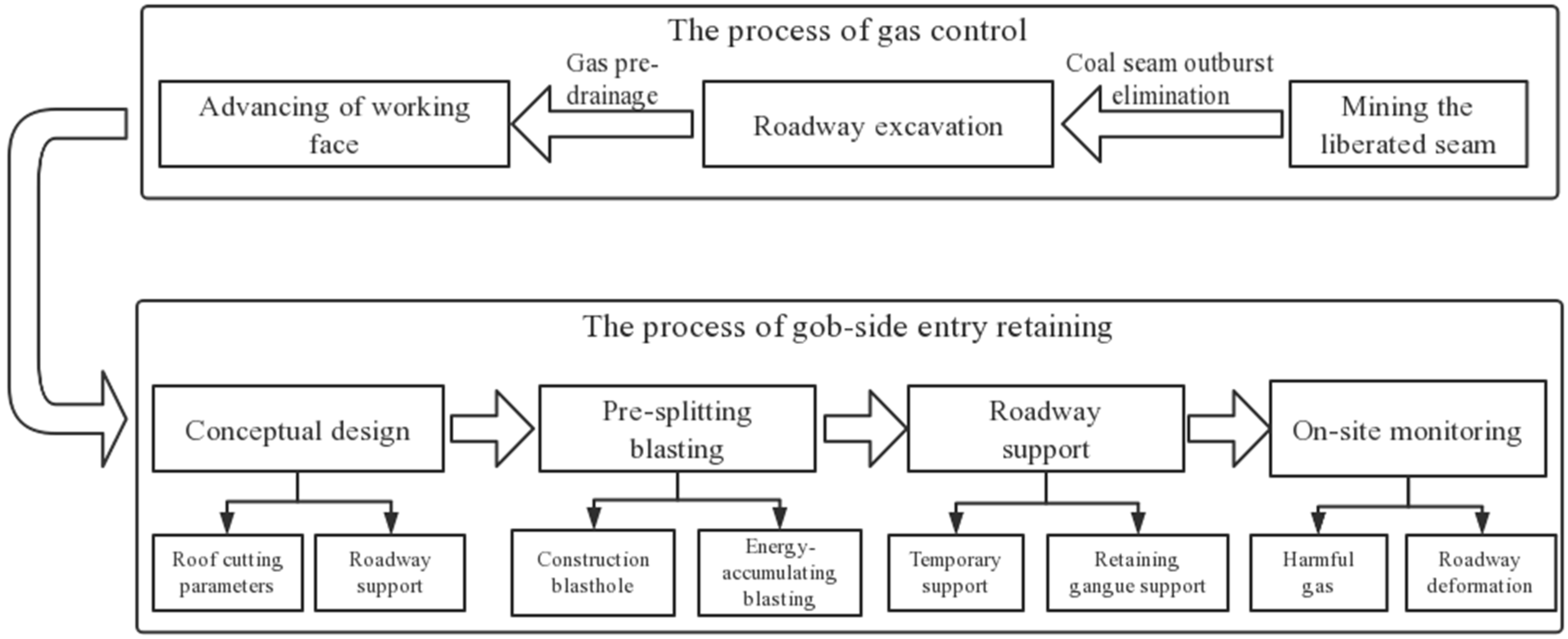
5. Engineering Practice
The whole process of gob-side entry retaining in the high gas outburst coal seam is shown in Figure 12. The mining of the liberation seam eliminates the danger of a coal seam outburst and provides satisfactory conditions for roadway excavation. After that, the working face began to advance, and the coal seam gas pre-drainage ensured the safety and efficiency in the process of coal seam mining.
The outburst danger of the coal seam gas was eliminated by mining liberated seam and pre-drainage coal seam gas, which created satisfactory conditions for gob-side entry retention. To keep the roadway along the mined-out area, the roof cutting parameters and the roadway support parameters were first determined. Then, blastholes were constructed and pre-splitting blasting was conducted, and support and temporary support in the process of roof cutting were deployed in a timely manner for gangue retention and to ensure the stability of the roadway.
5.1. Roadway Support
5.1.1. Retaining Gangue Support
As the 9# coal seam of the Honglin coal mine is a high gas outburst coal seam, in the design of the 39114 transport roadway gangue support mode, a layer of air duct cloth was installed in the mined-out area and fixed with iron wire mesh. This can prevent gas from flowing into the roadway from mined-out areas, effectively prevent air leakage, and preclude the spontaneous combustion of the coal seam caused by fresh air entering the mined-out areas.
5.1.2. Advanced Temporary Support
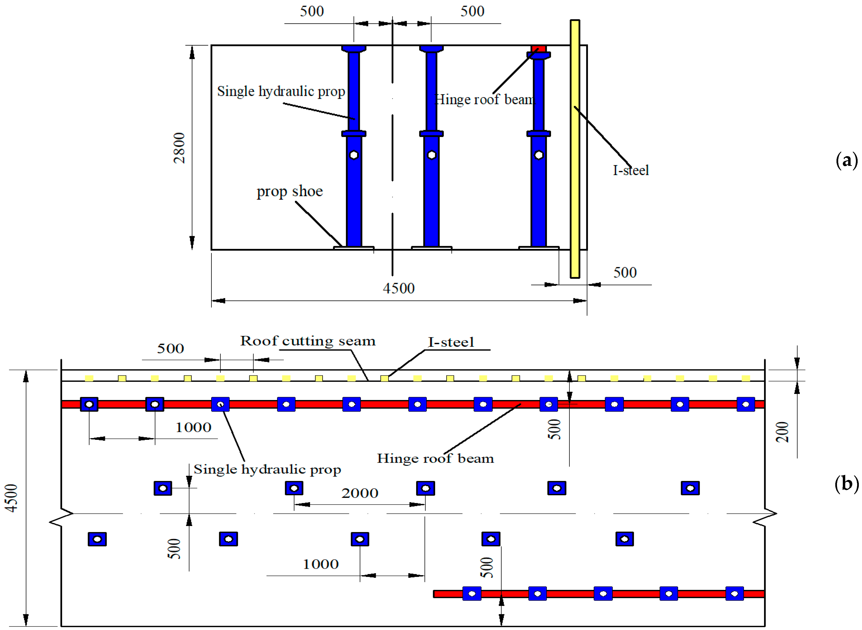
To prevent the influence of advanced stress concentration on the haulage roadway, single hydraulic props and hinged roof beams were used as advanced temporary support. The row spacing of the single hydraulic props was 1000 mm, which was 500 mm away from the roadway rib, as shown in Figure 15. The range of the advanced temporary supports was 50 m. The working face was advanced in the range of 0–20 m, and two rows of single hydraulic props were assembled along the roadway; then, when the working face was advanced in the range of 20–50 m, one row of single hydraulic props was assembled on the mined-out area side along the roadway, as shown in Figure 15. The effect of the on-site advanced temporary support is shown in Figure 16.
5.1.3. Delayed Temporary Support
Three rows of single hydraulic props were arranged along the roadway as delayed temporary support. On the roof cutting side, a single hydraulic prop with a hinged roof beam was used, and the spacing of the single hydraulic props was 1000 mm. In addition, a row of single hydraulic props was arranged on both sides of the roadway center-line, 500 mm away from the roadway center-line, and the row spacing of these single hydraulic props was 2000 mm. Figure 17 is the schematic diagram of the delayed temporary support, and the effect of the on-site delayed temporary support is shown in Figure 18.
5.2. On-Site Monitoring
As the 39114 working face did not have Y-line ventilation conditions, to prevent fresh air from flowing into the mined-out areas, sandbag walls were arranged behind the working face along the mined-out areas. This resulted in the inability to establish measuring stations in the retaining roadway. Therefore, ground pressure monitoring was only carried out in the roof cutting section.
5.2.1. Advanced Influence Range of Roof Cutting
To determine the advanced influence range of roof cutting, three stations were established along the 39114 haulage roadway, and one bolt in the middle of the roadway roof was selected to have a bolt dynamometer installed in it to monitor the working force. The monitoring stations were 60 m, 160 m, and 260 m away from the setup entry, and the monitoring results are shown in Figure 19.
As shown in Figure 19a, when the distance from the working face was 40–60 m, the working force of the bolts increased slowly, and when the distance from the working face was less than 20 m, the working force of bolts increased sharply. As shown in Figure 19b, the variation trend of the bolt working force at station 2# was basically consistent with that at station 1#. When the distance from the working face was greater than 50 m, the bolt working force increased slowly. When the distance was less than 40 m, the bolt working force increased rapidly. As shown in Figure 19c, when the distance from the working face was greater than 60 m, the working force of the bolt increased gently, and increased rapidly when the distance from the working face was less than 60 m.
It can be seen from Figure 19 that, with an increase in the advancing length of the working face, the working force of the bolts at the three stations showed an increasing trend. This also showed that, with the advance of the working face, the advance pressure of the roadway gradually increased and the deformation of the roadway continued to increase.
While monitoring the working force of the bolt, the deformation of the roof-floor and two ribs of the three stations were also monitored. The monitoring results are shown in Figure 20.
5.2.2. Harmful Gas Monitoring in Mined-Out Areas
The 9# coal seam in the Honglin Coal Mine is a high gas outburst coal seam. Although outburst elimination treatment was carried out before mining, residual gas accumulation may still occur in mined-out areas. In addition, due to the isolation of fresh air flow in the mined-out areas, the residual coal in the mined-out areas is prone to anaerobic oxidation to produce CO. Therefore, it is necessary to use a JSG-8 monitoring system to monitor the CH4 and CO concentration in the gas extraction pipeline in the mined-out areas. The JSG-8 is a mine fire beam tube monitoring system, which is an electronic product for monitoring and predicting underground natural fires. The system extracts the gas in the underground monitoring beam pipe to the ground through microcomputer control, and uses the gas chromatograph for analysis, which allows on-line monitoring of the content of CO, CO2, CH4, and other gases.
It can be seen from Figure 21 that the CH4 concentration and CO concentration in the extraction pipeline fluctuated slightly, but the CH4 concentration fluctuated around 4% and the CO concentration fluctuated around 0.06%. This shows that the concentration of harmful gases in the mined-out areas was relatively small, and the prevention and control of gas and fire in the mined-out areas was within a controllable range when gob-side entry retention was used.
6. Conclusions
- (1)
- The 39114 working face of the Honglin coal mine adopts the methods of mining the protective layer and gas pre-drainage to eliminate outbursts in the coal seam. After coal seam outburst elimination, the CH4 content of adjacent coal seams in the 39114 working face decreased by 50.2% and 56.1%, respectively, indicating that the mining of the liberated seam and gas pre-drainage can effectively control coal seam gas.
- (2)
- UDEC numerical simulation software was used to simulate different roof cutting heights and cutting angles. It was found that increasing the roof cutting height or cutting angle within a certain range can improve the volume of gangue fragmentation and reduce the unfilled space in the mined-out area, indicating that there are optimal values for cutting height and cutting angle.
- (3)
- After engineering practice was carried out on the 39114 working face by the use of determined optimal roof cutting parameters, the average maximum deformation of the roof was 98.3 mm and that of the two ribs was 62.3 mm. This shows that the technology of roof cutting, and keeping pressure-relief retaining roadways along mined-out areas, can effectively control roadway deformation.
- (4)
- The concentrations of CH4 and CO in the mined-out areas were monitored. The gas concentration in the mined-out areas fluctuated up and down around 0.3% and the CO concentration fluctuated up and down around 0.06%, indicating that retaining gangue support with an air duct cloth can effectively control the generation and escape of harmful gases.
- (5)
- The technology of gob-side entry retaining by roof cutting was feasible in the high gas outburst mine, and achieves the goal of safe and efficient mining.
Author Contributions
Formal analysis, D.Z.; investigation, Y.C.; resources, Z.M. and B.X.; writing—original draft preparation, D.Z.; writing—review and editing, Z.M.; project administration, W.Y. All authors have read and agreed to the published version of the manuscript.
Funding
The National Natural Science Foundation of China (Grant No. 51904080), Grant to Z.M.; and the Science and Technology Program of Guizhou Province of China (Grant No. [2021] general 352 No. [2021]3001) during the research.
Institutional Review Board Statement
The study did not require ethical approval.
Informed Consent Statement
Informed consent was obtained from all subjects involved in the study.
Data Availability Statement
This study did not report any data.
Acknowledgments
The authors of this paper would like to express their gratitude for the National Natural Science Foundation of China (No. 51904080) and the Science and Technology Project of Guizhou Province (No. 2021 general 352 and No. [2021]3001) during the research.
Conflicts of Interest
The authors declared that they have no conflict of interest.
References
- Xu, Y.; Bai, J.B.; Chen, Y.; Yue, J. Development of Scientific Mining: A Case Study of Gob-Side Entry Retaining Technology in China. Adv. Mater. Res. 2011, 255–260, 3786–3792. [Google Scholar]
- Zhang, N.; Yuan, L.; Han, C.; Xue, J.; Kan, J. Stability and deformation of surrounding rock in pillarless gob-side entry retaining. Saf. Sci. 2012, 50, 593–599. [Google Scholar] [CrossRef]
- Yang, H.; Cao, S.; Li, Y.; Sun, C.; Guo, P. Soft Roof Failure Mechanism and Supporting Method for Gob-Side Entry Retaining. Minerals 2015, 5, 707–722. [Google Scholar] [CrossRef] [Green Version]
- He, M.; Gao, Y.; Yang, J.; Gong, W. An Innovative Approach for Gob-Side Entry Retaining in Thick Coal Seam Longwall Mining. Energies 2017, 10, 1785. [Google Scholar] [CrossRef] [Green Version]
- Hu, J.; He, M.; Wang, J.; Ma, Z.; Wang, Y.; Zhang, X. Key Parameters of Roof Cutting of Gob-Side Entry Retaining in a Deep Inclined Thick Coal Seam with Hard Roof. Energies 2019, 12, 934. [Google Scholar] [CrossRef] [Green Version]
- Zhen, E.; Gao, Y.; Wang, Y.; Wang, S. Comparative Study on Two Types of Nonpillar Mining Techniques by Roof Cutting and by Filling Artificial Materials. Adv. Civ. Eng. 2019, 2019, 5267240. [Google Scholar] [CrossRef] [Green Version]
- Sun, X.; Liu, Y.; Wang, J.; Li, J.; Sun, S.; Cui, X. Study on Three-Dimensional Stress Field of Gob-Side Entry Retaining by Roof Cutting without Pillar under Near-Group Coal Seam Mining. Processes 2019, 7, 552. [Google Scholar] [CrossRef] [Green Version]
- Yang, X.; Sun, Y.; Wang, E.; Mao, W. Study and Application of Gob-Side Entry Retaining Formed by Roof Cutting and Pressure Relief in Medium-Thickness Coal Seam with Hard Roof. Geotech. Geol. Eng. 2020, 38, 3709–3723. [Google Scholar] [CrossRef]
- Wang, Q.; Jiang, B.; Wang, L.; Liu, B.; Li, S.; Gao, H.; Wang, Y. Control mechanism of roof fracture in no-pillar roadways automatically formed by roof cutting and pressure releasing. Arab. J. Geosci. 2020, 13, 274. [Google Scholar] [CrossRef]
- Xiao-Ming, S.; Gan, L.; Peng, S.; Chengyu, M.; Chengwei, Z.; Qi, L.; Xing, X. Application Research on Gob-Side Entry Retaining Methods in No. 1200 Working Face in Zhongxing Mine. Geotech. Geol. Eng. 2018, 37, 185–200. [Google Scholar] [CrossRef]
- Wang, Y.; Gao, Y.; Wang, E.; He, M.; Yang, J. Roof Deformation Characteristics and Preventive Techniques Using a Novel Non-Pillar Mining Method of Gob-Side Entry Retaining by Roof Cutting. Energies 2018, 11, 627. [Google Scholar] [CrossRef]
- Ma, Z.; Wang, J.; He, M.; Gao, Y.; Hu, J. Key Technologies and Application Test of an Innovative Noncoal Pillar Mining Approach: A Case Study. Energies 2018, 11, 2853. [Google Scholar] [CrossRef] [Green Version]
- Ma, X.; He, M.; Wang, J.; Gao, Y.; Zhu, D.; Liu, Y. Mine Strata Pressure Characteristics and Mechanisms in Gob-Side Entry Retention by Roof Cutting under Medium-Thick Coal Seam and Compound Roof Conditions. Energies 2018, 11, 2539. [Google Scholar] [CrossRef] [Green Version]
- Wang, Q.; He, M.; Yang, J.; Gao, H.; Jiang, B.; Yu, H. Study of a no-pillar mining technique with automatically formed gob-side entry retaining for longwall mining in coal mines. Int. J. Rock Mech. Min. Sci. 2018, 110, 1–8. [Google Scholar] [CrossRef]
- He, M.; Ma, X.; Yu, B. Analysis of Strata Behavior Process Characteristics of Gob-Side Entry Retaining with Roof Cutting and Pressure Releasing Based on Composite Roof Structure. Shock Vib. 2019, 2019, 2380342. [Google Scholar] [CrossRef] [Green Version]
- Shao, L.; Huang, B.; Zhao, X. Secondary Gob-side Entry Retaining Technology with Double Side Roof Cutting and Pressure Relief in Thin Coal Seam. Int. J. Oil Gas Coal Eng. 2020, 8, 91. [Google Scholar] [CrossRef]
- Zhu, Z.; Zhu, C.; Yuan, H. Distribution and Evolution Characteristics of Macroscopic Stress Field in Gob-Side Entry Retaining by Roof Cutting. Geotech. Geol. Eng. 2019, 37, 2963–2976. [Google Scholar] [CrossRef]
- Xingen, M.; Manchao, H.; Jiandong, S.; Jie, H.; Xingyu, Z.; Jiabin, Z. Research on the Design of Roof Cutting Parameters of Non Coal Pillar Gob-side Entry Retaining Mining with Roof Cutting and Pressure Releasing. Geotech. Geol. Eng. 2019, 37, 1169–1184. [Google Scholar] [CrossRef]
- Tian, C.; Wang, A.; Liu, Y.; Jia, T. Study on the Migration Law of Overlying Strata of Gob-Side Entry Retaining Formed by Roof Cutting and Pressure Releasing in the Shallow Seam. Shock Vib. 2020, 2020, 8821160. [Google Scholar] [CrossRef]
- Sun, B.-J.; Hua, X.-Z.; Zhang, Y.; Yin, J.; He, K.; Zhao, C.; Li, Y. Analysis of Roof Deformation Mechanism and Control Measures with Roof Cutting and Pressure Releasing in Gob-Side Entry Retaining. Shock Vib. 2021, 2021, 6677407. [Google Scholar] [CrossRef]
- Zhang, J.; Yang, F.; Wang, R.; Zheng, C.; Sun, N.; Lei, W.; Xu, T.; Zhang, J.; Miao, Z. Study on Optimum Design of Outburst Prevention Measures in Weijiadi Coal Mine. IOP Conf. Series Earth Environ. Sci. 2019, 252, 052098. [Google Scholar] [CrossRef]
- Hudeček, V.; Vaněk, M.; Černý, I. Economic Assessment of Methods of Coal and Gas Outburst Prevention in the Extraction of Coalfaces. New Trends Prod. Eng. 2020, 3, 379–393. [Google Scholar] [CrossRef]
- Hudecek, V.; Urban, P.; Stavtnoha, J. Problems of higher gas emission and coal and gas outbursts in the Czech Republic and other countries of the world. J. Mines Met. Fuels 2010, 58, 212–216. [Google Scholar]
- Xiao, F.; Duan, L.; Ge, Z. Floor fracture law of coal mining face and gas pre-drainage application. J. Coal 2010, 35, 417–419. [Google Scholar] [CrossRef]
- Chi, B.; Zhou, K.; He, M.; Yang, J.; Wang, Q.; Ma, X. Optimization of support parameters of roof cutting roadway in large mining height working face. Coal Sci. Technol. 2017, 45, 128–133. [Google Scholar] [CrossRef]
- He, M.; Ma, X.; Niu, F.; Wang, J.; Liu, Y. Adaptability research and application of fast coal pillar-free self-forming roadway with composite roof in medium-thick coal seam. J. Rock Mech. Eng. 2018, 37, 2641–2654. [Google Scholar] [CrossRef]
Figure 1.
Column diagram of the roof and floor lithology.
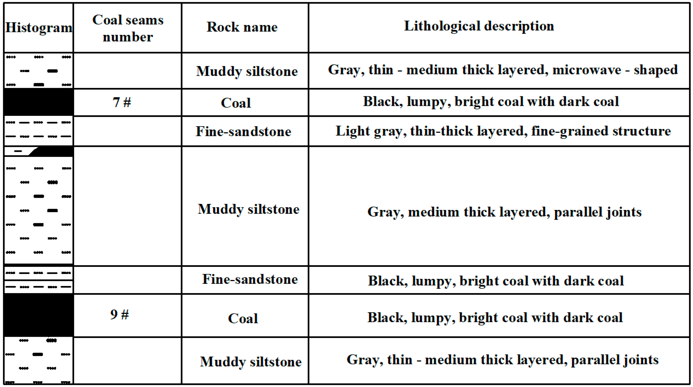
Figure 2.
Original roadway support parameters.

Figure 3.
Positional relationship and protected range of the liberated and protective seams.
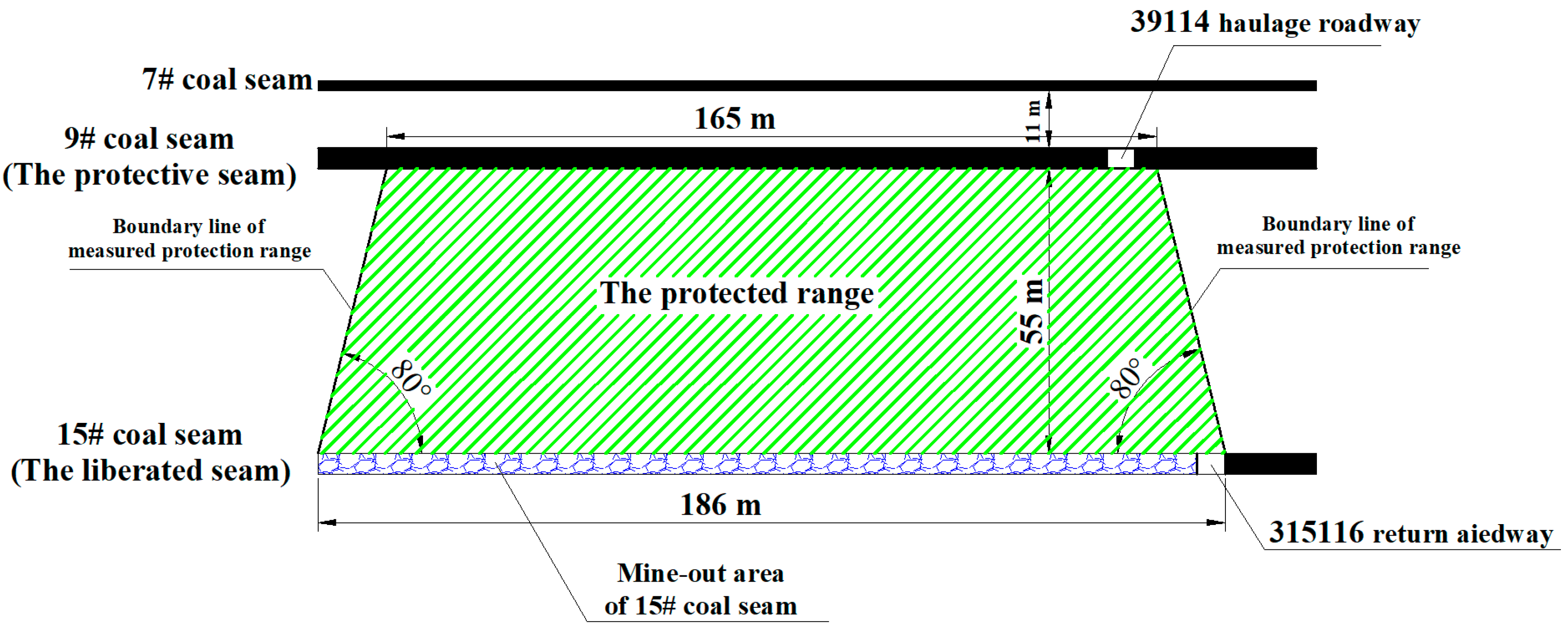
Figure 4.
Diagram of the arrangement of pre-drainage boreholes.

Figure 5.
Roof cutting diagram.
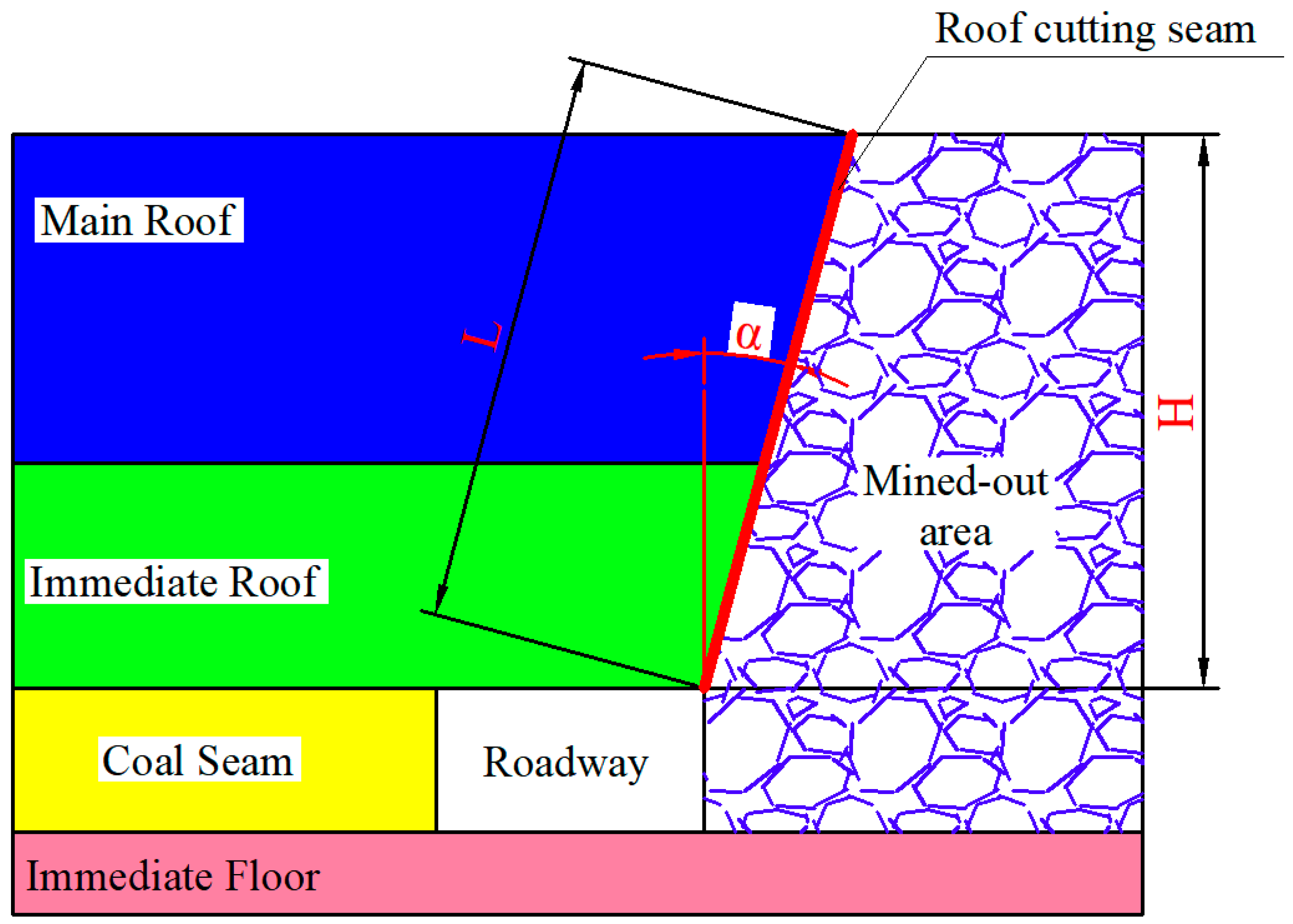
Figure 6.
Collapse morphology and vertical displacement model (unit: m). (a) Roof cutting height 5.5 m, (b) Roof cutting height 7 m, (c) Roof cutting height 8.5 m.
Figure 6.
Collapse morphology and vertical displacement model (unit: m). (a) Roof cutting height 5.5 m, (b) Roof cutting height 7 m, (c) Roof cutting height 8.5 m.

Figure 7.
Maximum deformation of the roadway roof for different cutting heights.
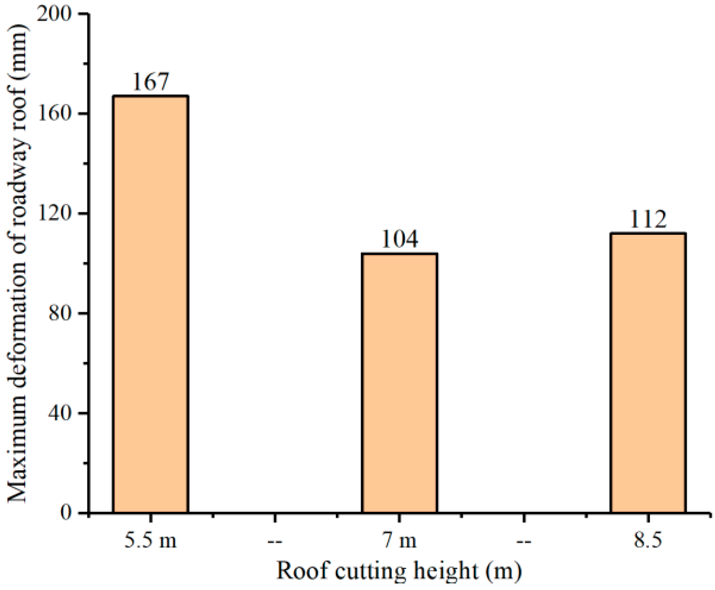
Figure 8.
Collapse morphology and vertical displacement model (unit: m). (a) Roof cutting angle 0°, (b) Roof cutting angle 10°, (c) Roof cutting angle 20°.
Figure 8.
Collapse morphology and vertical displacement model (unit: m). (a) Roof cutting angle 0°, (b) Roof cutting angle 10°, (c) Roof cutting angle 20°.
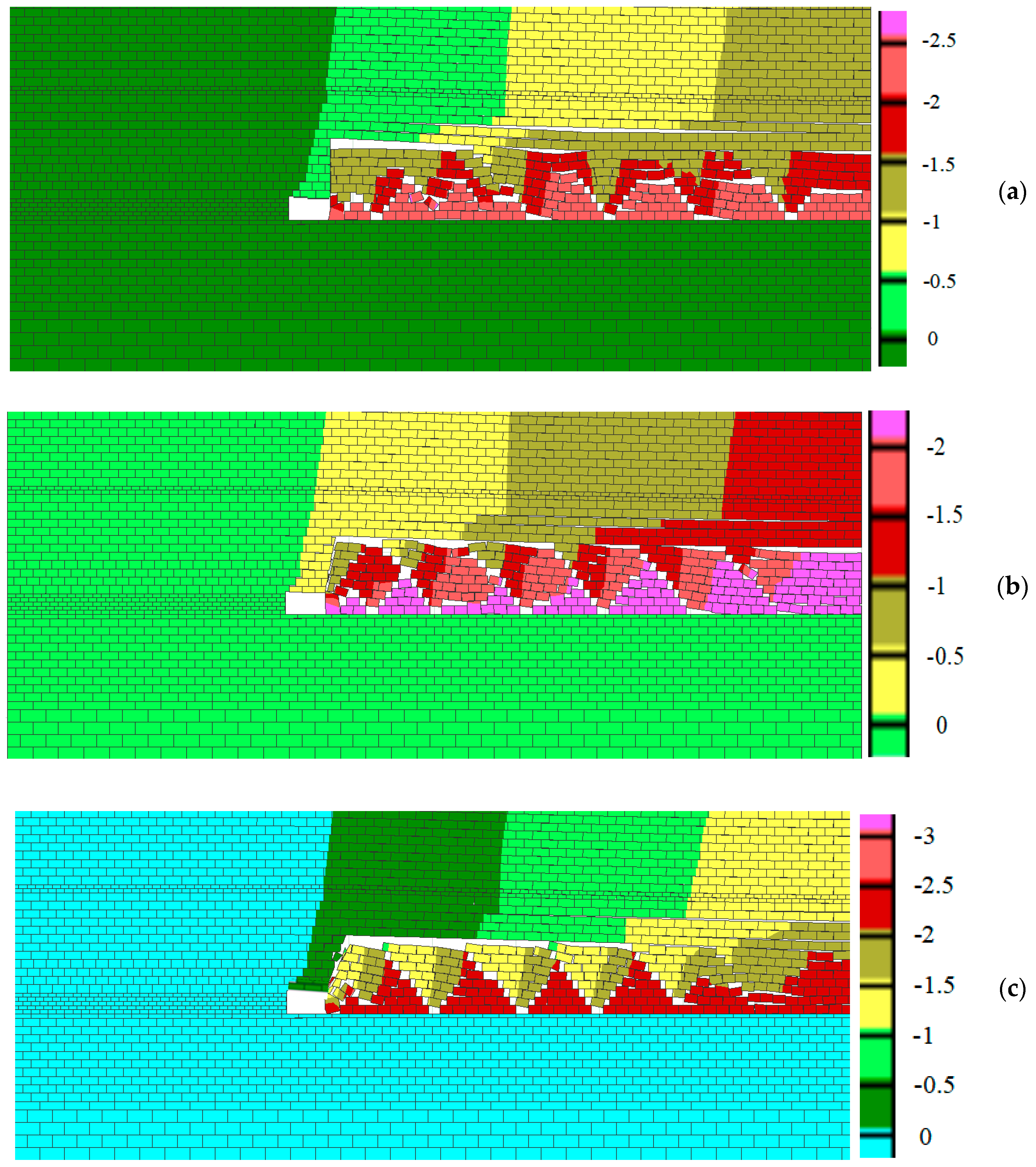
Figure 9.
Maximum deformation of the roadway roof for different cutting angles.
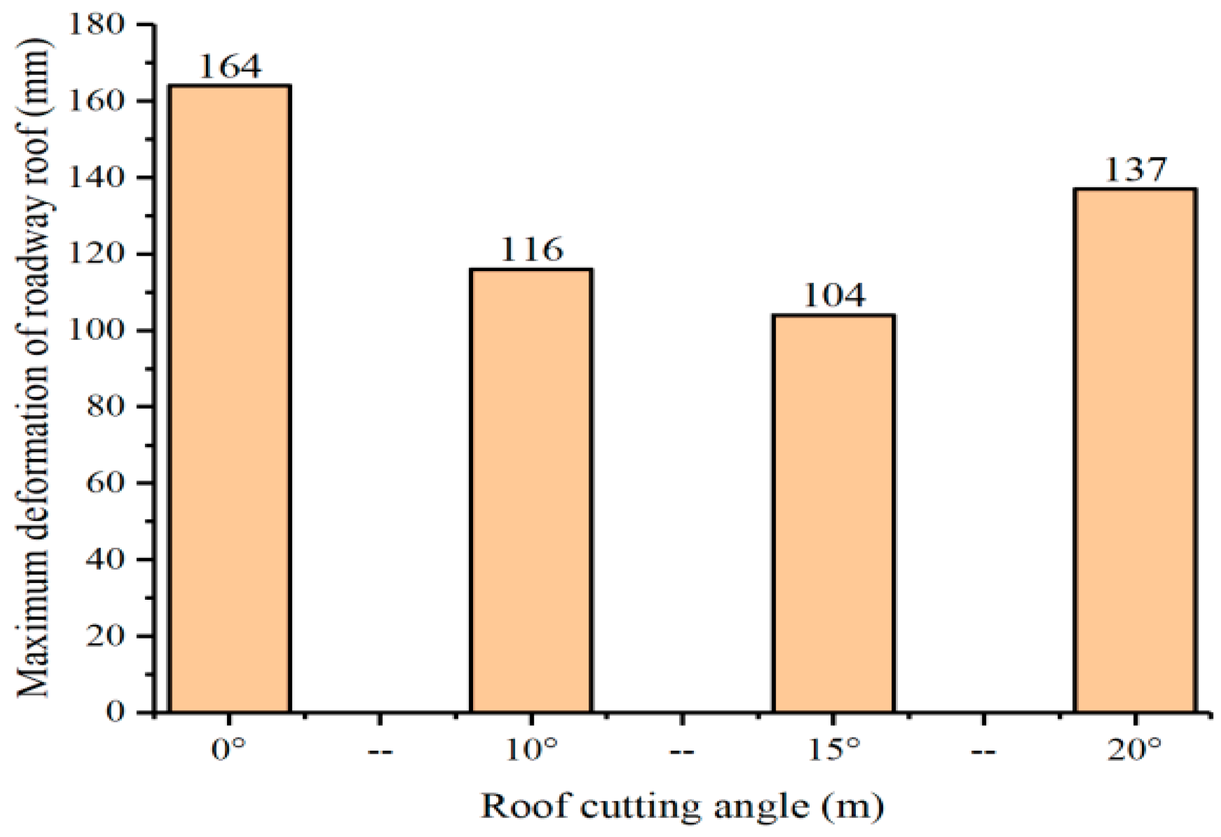
Figure 10.
Blast hole drilling peep with different spacing. (a) Spacing 500 mm (b) Spacing 600 mm (c) Spacing 700 mm.
Figure 10.
Blast hole drilling peep with different spacing. (a) Spacing 500 mm (b) Spacing 600 mm (c) Spacing 700 mm.
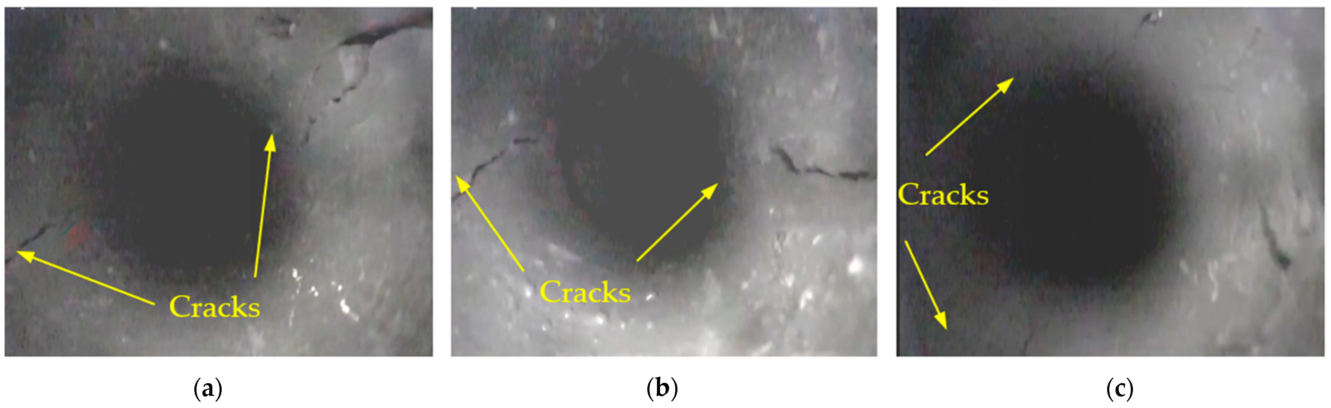
Figure 11.
Explosive charge structure.
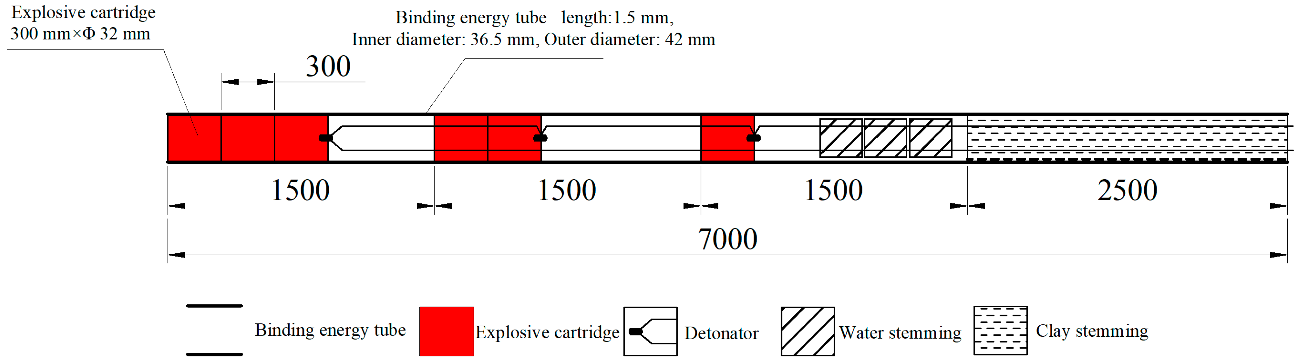
Figure 12.
Whole process of gob-side entry retention in a high gas outburst coal seam.

Figure 13.
Retaining gangue support schematic diagram.
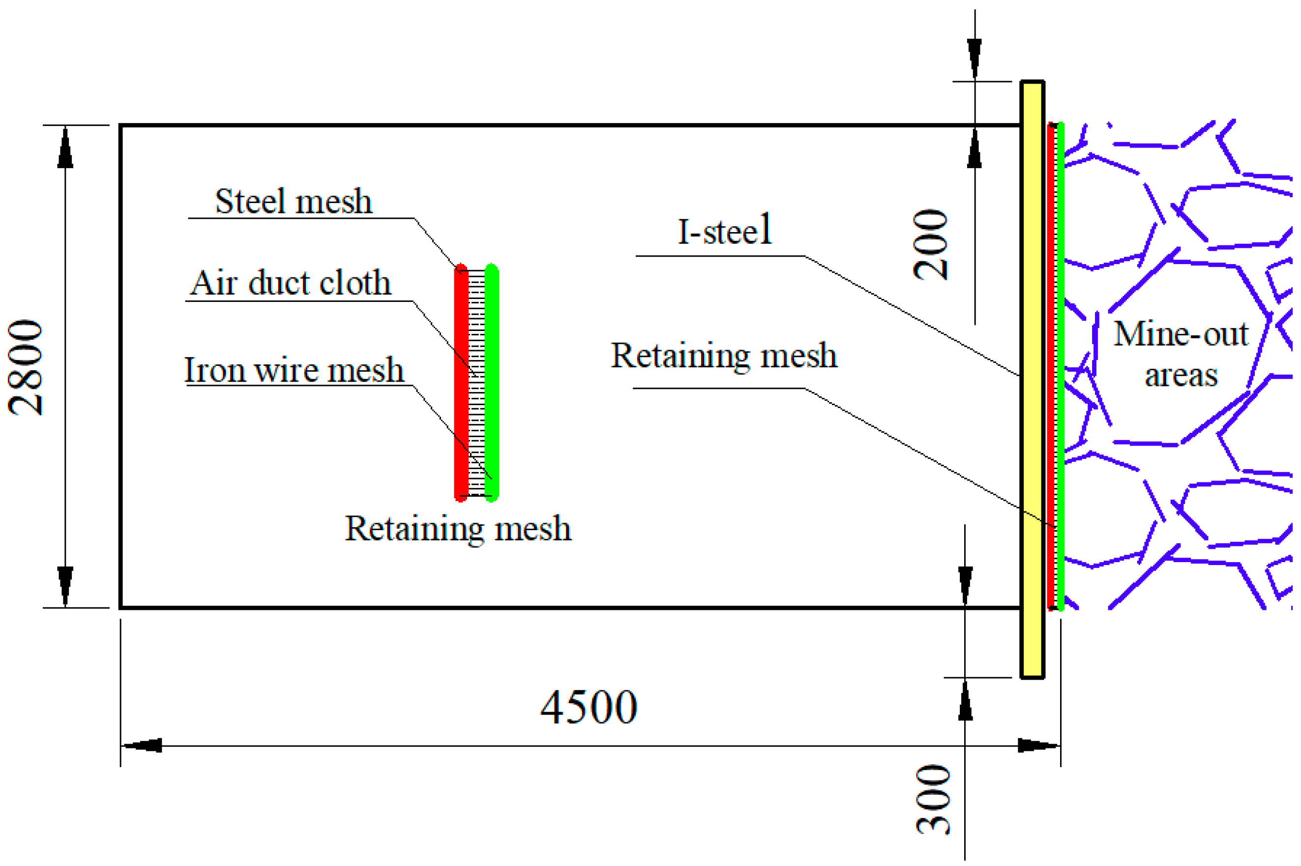
Figure 14.
On-site retaining support effect.

Figure 15.
Schematic diagram of the advanced temporary support (unit: mm). (a) Support section, (b) Support planar.
Figure 15.
Schematic diagram of the advanced temporary support (unit: mm). (a) Support section, (b) Support planar.
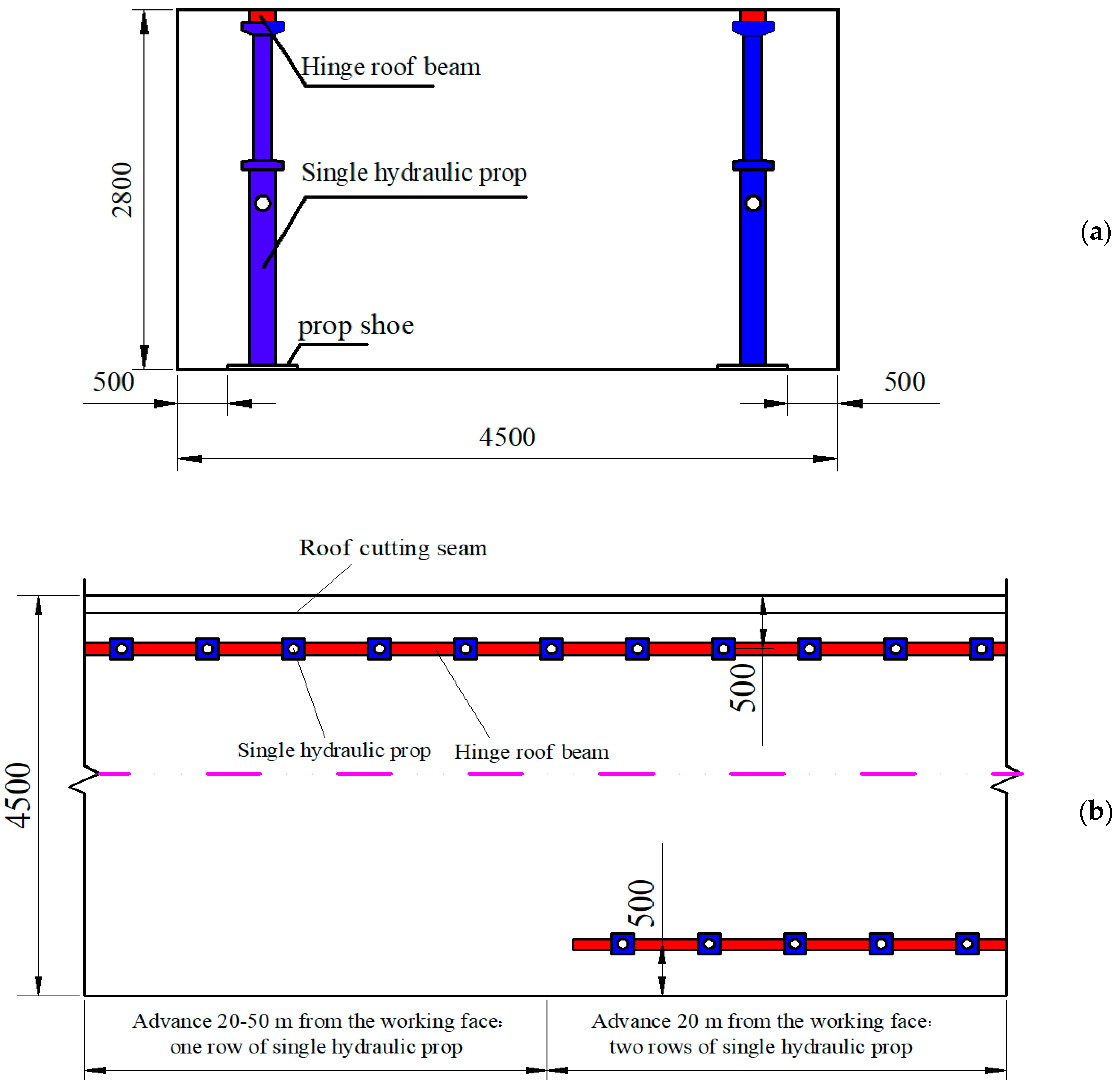
Figure 16.
Effect of on-site advanced temporary support.
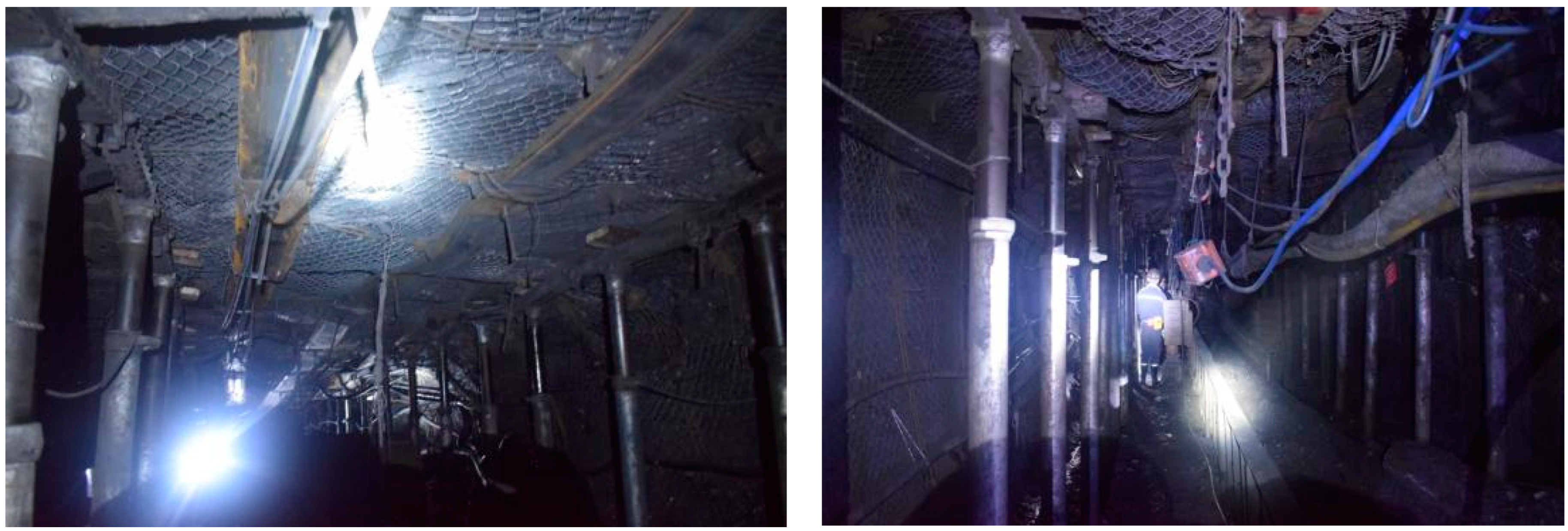
Figure 17.
Schematic diagram of the delayed temporary support. (a) Support section, (b) Support planar.
Figure 17.
Schematic diagram of the delayed temporary support. (a) Support section, (b) Support planar.

Figure 18.
Effect of on-site delayed temporary support.

Figure 19.
Force of bolts. (a) Station 1# (b) Station 2# (c) Station 3#.
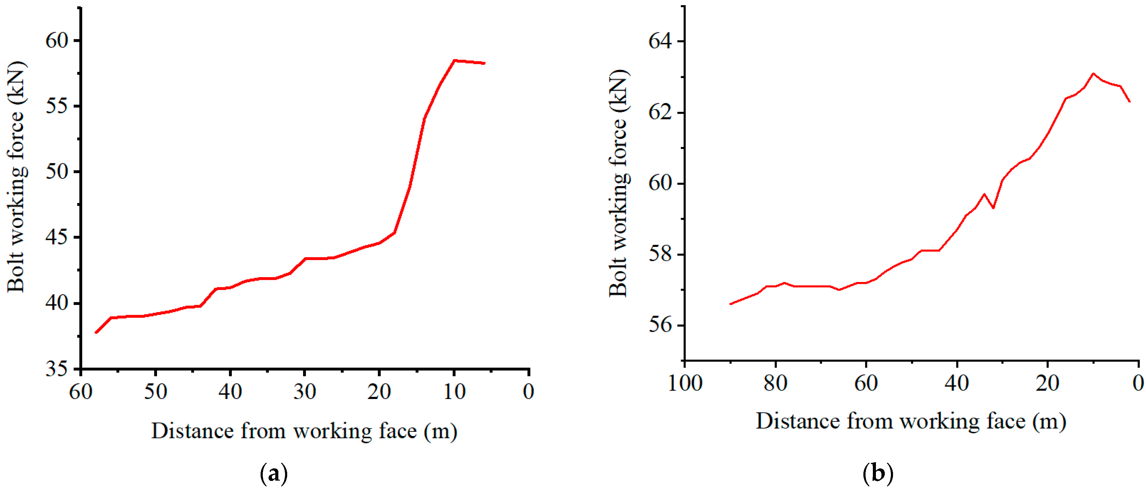
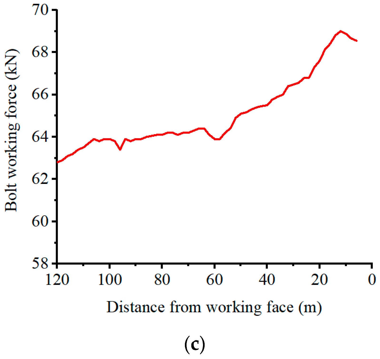
Figure 20.
Deformation of the roof-floor and two ribs. (a) Station 1# (b) Station 2# (c) Station 3#.
Figure 20.
Deformation of the roof-floor and two ribs. (a) Station 1# (b) Station 2# (c) Station 3#.
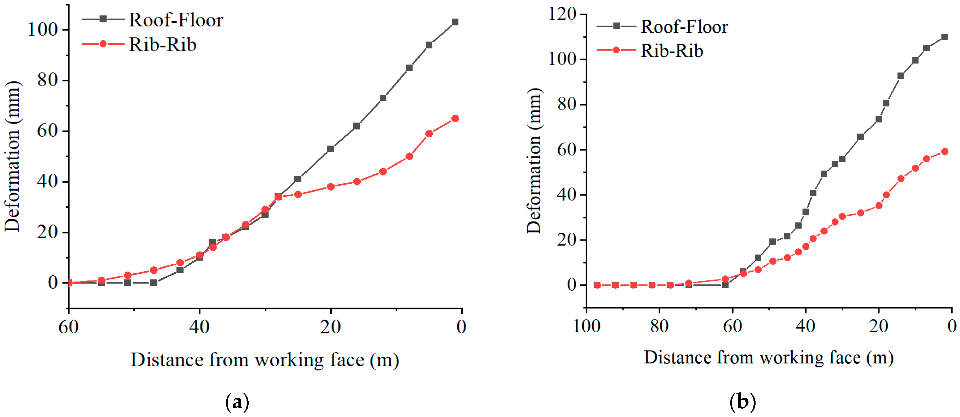
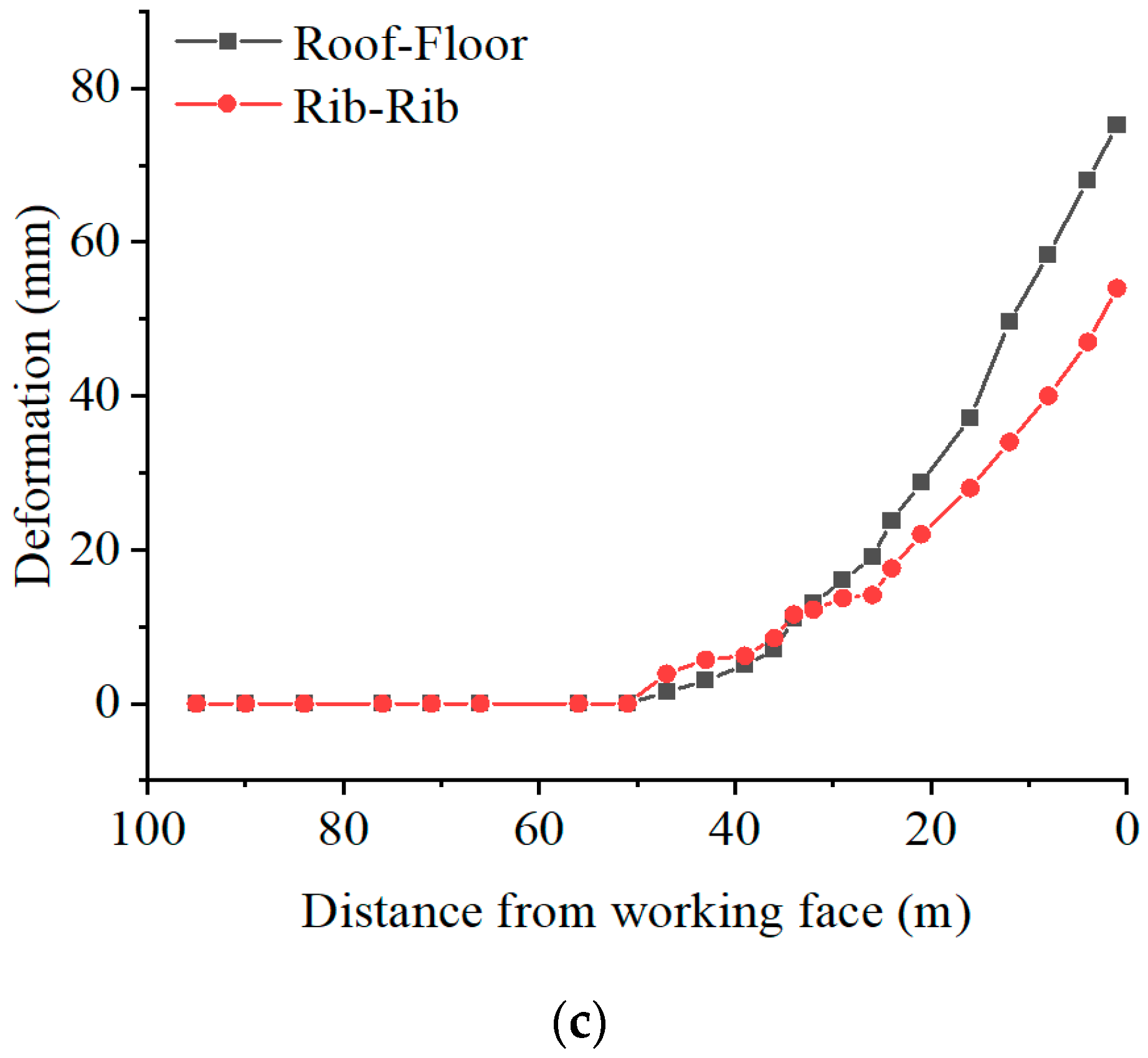
Figure 21.
Harmful gas monitoring over a period of one month. (a) CH4, (b) CO.


Table 1.
Gas parameters of the 7#, 9#, 15# coal seams.
| Coal Seam | Original Gas Content (m3/t) | Original Gas Pressure (MPa) |
|---|---|---|
| 7# | 12.46 | 0.08–0.58 |
| 9# | 13.9374 | 0.12–0.69 |
| 15# | 3.6 | 0.05–0.4 |
Table 2.
Design parameters of gas pre-drainage boreholes.
| 39114 Return Airway | ||||
| Number | Azimuth (°) | Dip Angle (°) | Design Length (m) | Spacing (m) |
| 1 | 89 | +28 | 47 | 0.38 |
| 2 | 110 | +25 | 48 | 0.38 |
| 3 | 126 | +20 | 55 | 0.38 |
| 4 | 138 | +15 | 64 | 0.38 |
| 5 | 146 | +11 | 76 | 0.38 |
| 6 | 152 | +8 | 88 | 0.38 |
| 39114 Haulage Roadway | ||||
| Number | Azimuth (°) | Dip Angle (°) | Design Length (m) | Spacing (m) |
| 1 | 77 | +29 | 48.5 | 0.3 |
| 2 | 60 | +28 | 54.2 | 0.3 |
| 3 | 47 | +26 | 63 | 0.3 |
| 4 | 38 | +23 | 74 | 0.3 |
| 5 | 31 | +21 | 85.5 | 0.3 |
| 6 | 27 | +19 | 98.2 | 0.3 |
Table 3.
Parameters of boreholes.
| Location | Number | Depth (m) | Azimuth(°) | Residual Gas Pressure (MPa) | Residual Gas Content (m3/t) |
|---|---|---|---|---|---|
| 39114 return airway (along the 9# coal seam) | 1 | 44 | 180 | 0.092 | 6.1033 |
| 87 | 180 | 0.094 | 6.1695 | ||
| 2 | 44 | 180 | 0.101 | 6.3613 | |
| 3 | 87 | 180 | 0.081 | 5.7999 | |
| 4 | 44 | 180 | 0.098 | 6.2805 | |
| 5 | 87 | 180 | 0.093 | 6.1316 | |
| 6 | 46 | 180 | 0.091 | 6.0843 | |
| 39114 haulage roadway (along 9# coal seam) | 1 | 54.2 | 0 | 0.08 | 5.7639 |
| 2 | 80.56 | 0 | 0.088 | 5.9996 | |
| 3 | 48 | 0 | 0.101 | 6.3538 | |
| 4 | 82 | 0 | 0.089 | 6.0343 | |
| 5 | 53 | 0 | 0.095 | 6.1963 | |
| 6 | 87 | 0 | 0.095 | 6.204 | |
| Average value | 0.092 | 6.114 | |||
| 39114 return airway (through the 7# coal seam) | 1 | 48.6 | 89 | 0.123 | 6.1639 |
| 2 | 76 | 146 | 0.13 | 6.3053 | |
| 39114 haulage roadway (through the 7# coal seam) | 1 | 45 | 35 | 0.121 | 6.1187 |
| 2 | 101.84 | 35 | 0.128 | 6.2756 | |
| Average value | 0.126 | 6.2159 | |||
Publisher’s Note: MDPI stays neutral with regard to jurisdictional claims in published maps and institutional affiliations. |
© 2022 by the authors. Licensee MDPI, Basel, Switzerland. This article is an open access article distributed under the terms and conditions of the Creative Commons Attribution (CC BY) license (https://creativecommons.org/licenses/by/4.0/).
Share and Cite
MDPI and ACS Style
Ma, Z.; Zhang, D.; Cao, Y.; Yang, W.; Xu, B. Study of Key Technology of Gob-Side Entry Retention in a High Gas Outburst Coal Seam in the Karst Mountain Area. Energies 2022, 15, 4161. https://doi.org/10.3390/en15114161
AMA Style
Ma Z, Zhang D, Cao Y, Yang W, Xu B. Study of Key Technology of Gob-Side Entry Retention in a High Gas Outburst Coal Seam in the Karst Mountain Area. Energies. 2022; 15(11):4161. https://doi.org/10.3390/en15114161
Chicago/Turabian StyleMa, Zhenqian, Dongyue Zhang, Yunqin Cao, Wei Yang, and Biao Xu. 2022. "Study of Key Technology of Gob-Side Entry Retention in a High Gas Outburst Coal Seam in the Karst Mountain Area" Energies 15, no. 11: 4161. https://doi.org/10.3390/en15114161
Note that from the first issue of 2016, this journal uses article numbers instead of page numbers. See further details here.