
A Geomechanical Model for Gas Hydrate Bearing Sediments Incorporating High Dilatancy, Temperature, and Rate Effects


1
Department of Civil and Environmental Engineering, Texas A&M University, 3136 TAMU, College Station, TX 77843, USA
2
PowerChina Huadong Engineering Corporation Limited, Hangzhou 311122, China
3
Instituto de Investigaciones Antisísmicas “Ing. Aldo Bruschi”, Facultad de Ingeniería, Universidad Nacional de San Juan, San Juan 5402, Argentina
4
Earth Science and Engineering, King Abdullah University of Science and Technology, Thuwal 23955, Saudi Arabia
*
Author to whom correspondence should be addressed.
Energies 2022, 15(12), 4280; https://doi.org/10.3390/en15124280
Submission received: 8 March 2022
/
Revised: 26 May 2022
/
Accepted: 28 May 2022
/
Published: 10 June 2022
(This article belongs to the Special Issue Experimental and Numerical Simulation of Methane Hydrate Geological Systems)
Abstract
:The geomechanical behavior of methane hydrate bearing sediments (MHBS) is influenced by many factors, including temperature, fluid pressure, hydrate saturation, stress level, and strain rate. The paper presents a visco-elastoplastic constitutive model for MHBS based on an elastoplastic model that incorporates the effect of hydrate saturation, stress history, and hydrate morphology on hydrate sediment response. The upgraded model is able to account for additional critical features of MHBS behavior, such as, high-dilatancy, temperature, and rate effects. The main components and the mathematical formulation of the new constitutive model are described in detail. The upgraded model is validated using published triaxial tests involving MHBS. The model agrees overly well with the experimental observations and is able to capture the main features associated with the behavior of MHBS.
1. Introduction
Methane hydrates are crystalline structures consisting of methane trapped in frozen-water molecules cages (e.g., [1,2]). They are stable at high pressure (P) and low temperature (T), and are generally found in seabed sediments and permafrost settings in the hydrate (P-T) stability zone. Methane hydrates bearing sediments (MHBS) are stable soils, however if changes in pressure and/or temperature (and/or chemical conditions) shift the hydrate outside the (P-T) stability zone, the methane-hydrate dissociates releasing gas-methane and liquid-water (e.g., [3,4,5,6,7]). According to Ruppel and Kessler [8], the global amount of methane carbon buried in MHBS is estimated to be close to 2000 gigatons.
The vast amount of methane hydrate hidden in both Arctic permafrost and marine continental margins worldwide has the potential to satisfy present and future global energy demand, provided efficient and economical production strategies are developed (e.g., Makogon et al. [9]). However, this is a challenging task owing to the complex behavior exhibited by methane hydrates upon dissociation (e.g., [6,10]). For example, the large volume changes related to hydrate dissociation (i.e., 1 m3 of hydrate produces during dissociation approximately 164 m3 of free gas and around 800 L of water) triggers significant increments in the fluid pressures, resulting in effective stress reduction, with the associated sediment deformations and changes in both soil porosity and permeability. Furthermore, because hydrate dissociation is a strong endothermic reaction, the reduction of the sediment temperature may freeze the pore water, blocking the sediment permeability. Moreover, methane production is generally accompanied with sand migration, which impact on both borehole mechanical stability and fluids flow. Sand production is considered as one of the major limitations for the commercial exploitation of gas hydrate (e.g., [11,12]). It is then apparent that the profound perturbations in the sediment condition and the multiphysics nature of this problem, with the strong couplings between the different thermo-hydro-mechanical and chemical (THMC) phenomena that control the sediment behavior require the development of advanced and robust models.
The interest in studying the behavior of MHBS does not only limit to energy production, but it also impacts on the stability of wellbores, offshore platforms, pipelines, and others subsea structures associated with hydrocarbon production. In addition, hydrate dissociation could trigger submarine landslides, which may affect underwater infrastructure. Furthermore, uncontrolled release of methane from hydrates will severely contribute to greenhouse effects and ocean warming (e.g., [8,13]). For example, after hydrate dissociation from submarine MHBS, the gas methane is not directly released to the atmosphere, but it is transformed (after biochemical processes in the ocean) into carbon dioxide, resulting in oxygen consumption and alterations in the chemical composition of the sea water (e.g., [14]). Therefore, the uncontrolled release of methane could severely harm our environment because the amount of carbon dioxide produced and released in this process is considerable.
One possible solution to safely produce energy from MHBS is via the exchange of methane by carbon dioxide in the hydrate cage (i.e., CO2-CH4 exchange). It has been proven in the laboratory that this replacement is energetically favorable and effective (e.g., [15,16,17]). The CO2-CH4 hydrate exchange will solve two problems simultaneously, i.e., stability of the hydrate bearing sediment during methane production, and capture of carbon dioxide in the sediment. However, the practical implementation of this technique in the field still requires further research and in-situ testing.
From the discussion above, we can conclude that a good understanding and modelling of MHBS is a critical component to address the challenges and opportunities associated with this type of sediment. The geomechanical behavior of MHBS is particularly challenging. Experimental studies in this area have primarily focused on how the strength, stiffness, and others mechanical properties of MHBS are affected by the following factors: hydrate saturation (e.g., [6,18,19,20]), effective mean stress (e.g., [21]), confining pressure (e.g., [22]), temperature (e.g., [23,24,25,26,27,28,29,30]), pore pressure e.g., [31]), strain rate (e.g., [32,33,34,35,36,37,38,39,40,41]), drainage conditions (e.g., [42]), and sediment skeleton (e.g., [20,43]).
Several THMC formulations and computer codes have been proposed to model the behavior of MHBS (e.g., [44,45,46,47,48,49,50,51,52,53]). In particular, several constitutive models have been proposed in the last few years to simulate the mechanical behavior of MHBS. The initial efforts in this area assumed and elastic behavior of the material. For example, the Duncan and Chang [54] model was proposed to formulate nonlinear elastic models for MHBS (e.g., [23,55,56,57,58]). An extended Mohr-Coulomb model (MCM) able to account for the influence of hydrate dissociation on strength (which is considered via a linear decrease in the cohesion) was proposed by Freij-Ayoub et al. [29] to evaluate wellbore stability. Extended MCMs that include the influence of hydrate saturation on both material strength and stiffness were also adopted to simulate the behavior of MHBS (e.g., [46,59,60,61]). More recent developments used critical state concepts ([62]) to model the response of MHBS. This type of approaches generally incorporates the effect of hydrate saturation, hydrate morphology, and other key MHBS factors into the mathematical formulation (e.g., [63,64,65,66,67,68,69,70,71,72]). The strains partition concepts proposed by Pinyol et al. [73] to model claystones was adopted by Sanchez et al. [68] to develop a model for MHBS able to evaluate the relative contribution of both sediment-skeleton and methane-hydrate to the mechanical behavior of the material. As for the effect of temperature on MHBS behavior, Yu et al. [28] propose a temperature dependent nonlinear elastic model and consider the effect of temperature on the initial modulus of the sediment. The upgraded Duncan-Chang model developed by Song et al. [23] adopts two coefficients to account for the effect of temperature and hydrate dissociation on the mechanical behavior of MHBS. The time-dependent behavior of hydrate bearing sediment have been mainly simulated using viscoelastic concepts (e.g., [37]). The THM formulations for MHBS proposed in Kimoto et al. [38] and Akaki et al. [39] adopted a mechanical model based on viscoplastic concepts, however the mechanical law was not validated. In Deusner et al. [40], the rate-dependent behavior of MHBS was explained considering a mechanism based on the kinematic rearrangement of the material fabric.
In this paper we present the extension of an existing model to deal with features of MHBS that have received less attention in the constitutive modeling of this type soil, such as, the influence of temperature, high dilatancy, and strain-rate effects. The starting point is the elastoplastic mechanical for MHBS proposed by Gai and Sanchez [67] which is able to account for the impact of methane-hydrates saturation on pre-consolidation stress, material stiffeners, and strength. The model was able to satisfactorily capture the overall MHBS experimental behavior observed in triaxial tests under different conditions. However, this model was not formulated to consider temperature and strain-rate effects. In this work we extend the original model (i.e., Gai and Sanchez [67]) to account for these two effects, and we also propose and enhanced hardening law to capture better the high dilatant behavior typically observed in MBHS. In the following sections we present first the mathematical formulation of the upgraded model, and we then evaluate the model performance when compared against published experimental results.
2. Methodology
We focused our efforts on the development of an advance geomechanical model for MHBS. The constitutive model is formulated in the general framework of viscoplasticity and adopts Perzyna’s theory [74] to extend an inviscid elastoplastic model to handle rate effects in soils. The proposed model is then validated based on available data in the literature. In this section, we present first some basic aspects associated with MHBS, we then briefly introduce the model proposed by Gai and Sanchez [67], afterward we extend it to handle soils exhibiting high dilatancy, non-isothermal conditions, and rate effects.
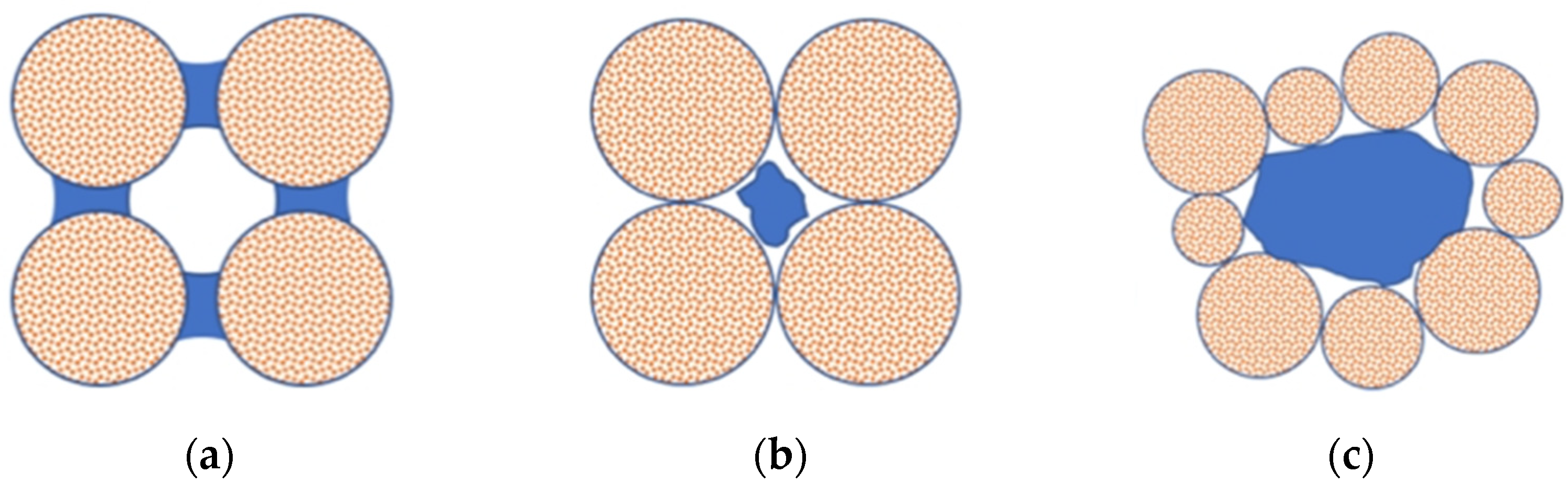
Methane hydrate saturation (SH: ratio between the volume of hydrates and the volume of voids) has a strong influence on the mechanical response of MHBS. It has been shown that stiffness, peak deviatoric stress, and dilation of the MHBS specimens increase with SH (e.g., [18,75]). However, the impact of methane-hydrates on sediment behavior not only depend on the amount of hydrates, but also on its morphology. Gas hydrates are generally found in three main form types in the sediment structure (Figure 1): (a) cementation, (b) pore-filling, and (c) supporting matrix (e.g., [1,76]). In the first pore-habit type, the methane-hydrates are mainly present at the contact between the grains and they act as a bonding material. In the pore filling form, the hydrates generally tend to grow freely in the pore space, without bridging particles together. Hydrates in the supporting matrix form are part of the solid skeleton. For a similar hydrate concentration, the cementing type hydrate morphology provides the maximum stiffness, strength and dilatancy (e.g., [18]).
In the following Section 2.1 we briefly present Gai and Sanchez [67] model and then its upgrade to handle high-dilatancy, temperature, and time-dependent behavior in Section 2.2, Section 2.3 and 2.4, respectively. In Section 3.1, Section 3.2 and Section 3.3 we present the model validation using published experimental data from triaxial tests.
2.1. Basic Model for MHBS—Brief Introduction
The starting point is the mechanical constitutive model for methane hydrate-bearing soils presented in Gai and Sanchez [67]. The model adopts a hierarchical single surface (HISS) proposed by Desai et al. [77] and Desai [78], and incorporates some key ingredients initially proposed by Uchida et al. [79] to deal with particular features of MHBS, namely: sub-loading concepts (e.g., [80,81]); cementing effects associated with the presence of hydrates; and bonding damage during shearing. The shape of the continuous HISS yield surface can be adapted to the particular conditions of the soil under investigation depending on the selected parameters. The HISS-MHBS model [67] is able to account for cementing effects, hydrate morphologies, and for the effect of confinement. The performance of the HISS-MHBS model was very satisfactory when compared against experimental data from triaxial tests based on natural core specimens and synthesized samples involving different hydrate saturations, hydrate morphology, and confinements [67]. However, the model underpredicted the volume expansion observed in tests involving hydrate bearing soils exhibiting high-dilatancy behavior. The model was not developed originally to handle the effect of both temperature and loading-rate on MHBS response. In the next sections we present the upgrade of the model to handle these relevant features of MHBS behavior.
The yield function of the HISS-MHBS model incorporating the strength enhancement effects (related to the presence of methane hydrate) and sub-loading concepts can be written as [67]:
where the constants a and are related to the shape of the yield surface; n is a parameter associated with the transition from compressive to dilative volume change; p’ and q are the mean effective and deviatoric stresses, respectively; M is the slope of critical line in the q − p’ space; pc is the effective pre-consolidation mean stress (which control the size of the elastic domain), and pd controls the increase of the sediment strength associated with the presence of hydrates.
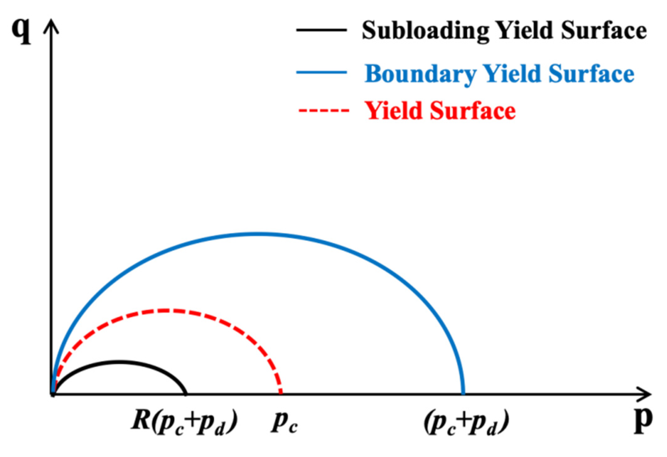
The evolution variable R (with 0 < R ≤ 1) is related to the sub-loading yield surface, which is introduced into the mathematical formulation to model: (i) irrecoverable strains that may develop when the stress state is inside the yield surface (aspect that cannot be modeled with a standard elasto-plastic model), and (ii) a smooth transition between elastic and plastic states. Figure 2 illustrates the three yield surfaces we consider in this model.
The hardening law is isotropic and depends on the plastic volumetric strains (εvp):
where e is void ratio; κ and λ are the slopes for the elastic and plastic isotropic paths in the e − (ln)p’ plane; respectively; and is the volumetric plastic strain
The other equations related to model formulation are introduced in the Appendix A. In the Appendix we also explain how the basic model accounts for the effect of both SH and hydrate morphology, more details can be found in Gai and Sanchez [67].
2.2. Model Upgrade to Consider MHBS Exhibiting High Dilatancy
Owing to the additional bonding provide by hydrates and the complex interactions between hydrates and soil skeleton, hydrate bearing soils generally exhibits high dilation. This feature of MBHS behavior is challenging to model (i.e., [67,82]). To overcome this issue the upgraded model incorporates an enhanced strain hardening law that depends on both, shear and volumetric plastic strains. The new hardening law extends Equation (2):
where is the deviatoric plastic strains; and is a parameter proposed by Nova [83] to control the effect of the deviatoric strain on hardening. This parameter varies between 0 and 1. The validation of this model is presented in Section 3.1.
2.3. Model Upgrade to Incorporate the Effect of Temperature on MHBS Behavior
The study of thermal effects on soil behavior has attracted growing attention in the last few years, particularly because of the increasing number of non-isothermal problems in energy geotechnics ([84]), such as, energy geostructures (e.g., [85,86]), and high-level nuclear waste disposal (e.g., [87,88,89]). It has been observed that temperature affects soil behavior in different manners, e.g., thermal volumetric strains depend on the stress history, the initial elastic modulus increases with the increase of temperature; and the preconsolidation pressure decreases with the temperature increase. It also appears that the friction angle at critical state and the normally consolidated line are independent of temperature. Campanella and Mitchell [90] proposed the first conceptual framework to consider the effect of temperature on soil behavior. Afterward, Hueckel and Baldi [91] adopted plasticity theory to model the thermomechanical behavior of saturated soils. Then, these ideas were extended by Gens [92] to model the behavior of unsaturated soils under non-isothermal conditions. Thermo-plastic models for soils were improved in subsequent research (e.g., [85,93]).
As discussed in the introduction, most of the analyses associated with the effect of temperature on MHBS have been based on thermal-dependent nonlinear elastic models (e.g., [23,28]). However, several laboratory investigations (e.g., [6,20,31,94,95,96]) focused on the behavior of MHBS in the hydrate-stability zone indicate that the thermal effects impact on their mechanical response beyond the elastic domain. In this section we extend the constitutive model presented in Section 2.1 to account for the effect of temperature in the MHBS hydrate stability zones. The extension of the HISS-MHBS model to account for thermal effects considers a dependence of the pc (Equation (1)) on temperature, as suggested in Laloui and Cekerevac [93] for other type of soils:
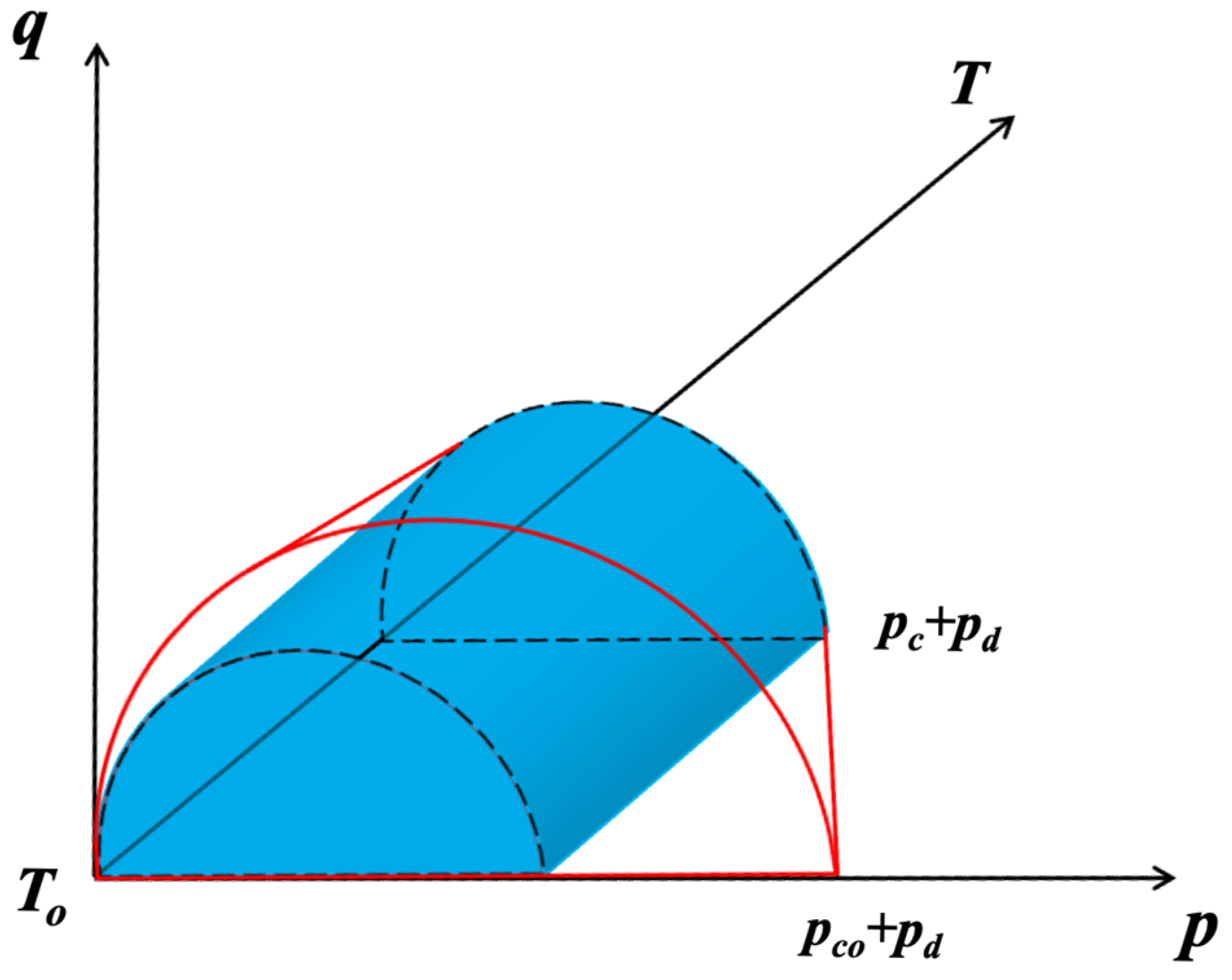
where T0 is the reference temperature, pc0 is the preconsolidation mean stress at T0, and rT is a model parameter that considers the effect of temperature on the preconsolidation pressure. Figure 3 illustrates the effect of temperature on the MHBS yield. The validation of this model is presented in Section 3.2.
2.4. Model Upgrade to Consider Rate-Dependent Effects on the Behavior of MHBS
The time-dependent behavior of soils has been investigated for a long time. Particular emphasis has been placed in the understanding of creep phenomena in soils (e.g., [97,98,99]). The impact of strain-rate on shear behavior of soils has also been intensively studied (e.g., [100,101,102,103]). Rate effects in soils have been generally modeled with success using viscoplastic models (e.g., [104,105,106]). The interest of rate effects on the behavior of MHBS has increased in the last few years. Triaxial tests at different strain rates based on both artificial samples and natural specimens have been conducted by Miyazaki et al. [32,33,34,35,36] and Yoneda et al. [41], respectively. As for modeling, Miyazaki et al. [37] proposed a nonlinear viscoelastic constitutive equation and validated against tests conducted at different strain-rates on artificial methane-hydrate-bearing sand specimens. Kimoto et al. [38] and Akaki et al. [39] implemented a viscoplastic model in a coupled THM formulation to solve boundary value problems involving MHBS. However, the mechanical model was not validated in these works.
In this research we adopt the well-known Perzyna’s overstress theory [74] to extend the model presented in the previous sections to account for rate-dependent effects in MHBS. Perzyna’s concepts allow upgrading in a single manner elastoplastic constitutive models to include viscoplastic behavior. Perzyna’s approach has been successfully applied to develop several stress-strain rate-dependent models for soils (e.g., [107,108,109,110,111,112]). In this theory, stress states outside the yield surface are allowed and the distance between the yield surface (i.e., from the previous time step) and the predictor stress (associated with the new time/strain increment) is a measured of the rate of the viscoplastic strains.
Perzyna’s overstress concept is typically expressed through the following equation (e.g., [74,113]):
where is the Macaulay brackets, is a scalar function (called sometimes the flux function [113]) that grows monotonically with F and defines the magnitude of the plastic strain rate.
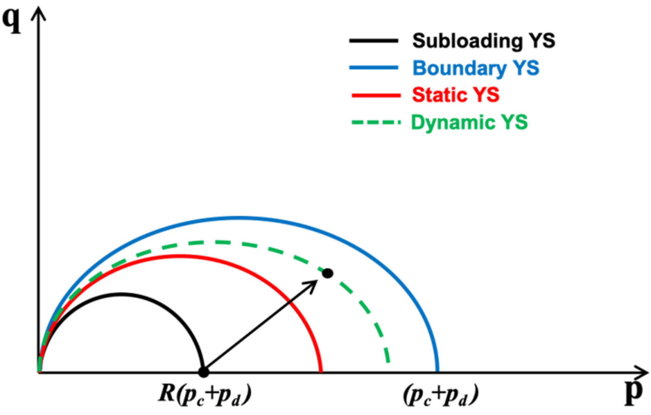
The elastoplastic yield surface from the previous time-step is generally called the ‘static yield surface’ (FS), and the homothetic yield surface passing through the current (predictor) stress state during yielding (i.e., outside FS) is often called the ‘dynamic yield surface’ (FD) (e.g., Hinchberger and Rowe [111]). In our model FS and FD are given by Equation (1), depending on whether we use the stresses and internal variables at the beginning of the time step (identified with the subscript S), or the stresses and internal variables associated with the predicted stresses (identified with the subscript D), respectively.
The direction of the viscoplastic strains is given by the gradient of the plastic potential function at the (current) predicted stress point (GD) calculated with the following equation (assuming associated plasticity):
The visco-plastic strain rate is given by the following equation:
where is a model parameter called fluidity.
As for the flow function, we adopted the following expression, Desai and Zhang [114]:
where f is the over-stress index; f0 a reference value (i.e., such that the expression is non-dimensional); and nf is a model parameter. Note that in this initial model we do not propose any dependence of the flow function on hydrate concentration, but it can be incorporated if needed. The over-stress index is calculated using the internal (static) variables at ‘S’ and the predicted (dynamic) stresses ‘D’, as follows:
and the viscoplastic strains are obtained after:
The static and dynamic yield surfaces are updated during yielding. Figure 4 shows the yield surfaces adopted in this work. The validation of this model is presented in Section 3.3.
3. Results and Discussions
In the following sections we present the application and validation of the upgraded model based on published experimental results.
3.1. Model Application Involving MHBS Exhibiting Large Dilation
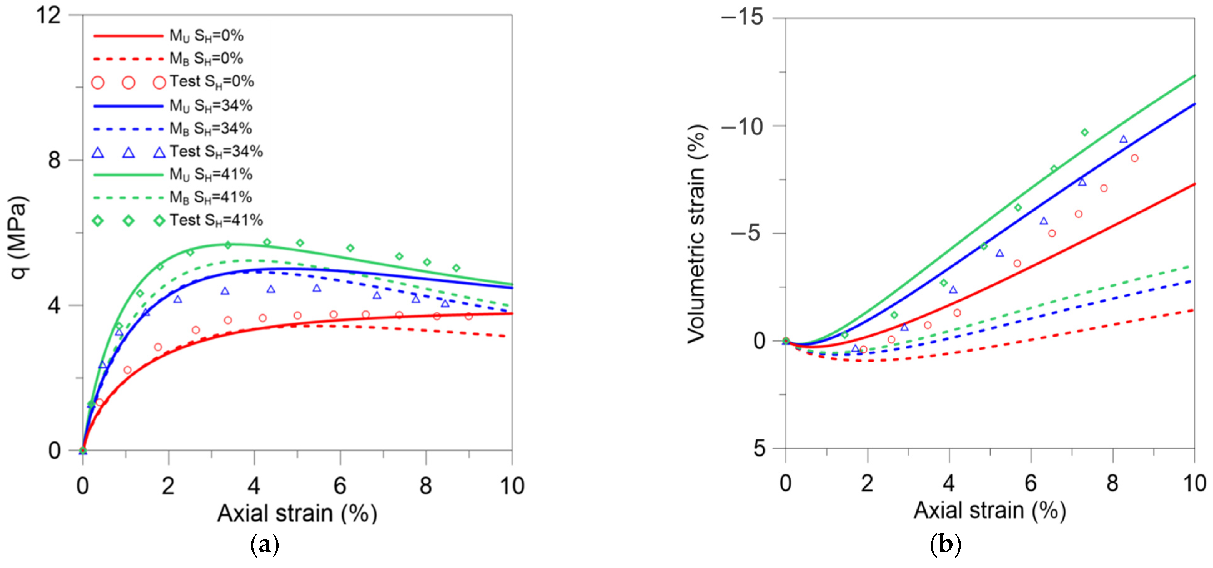
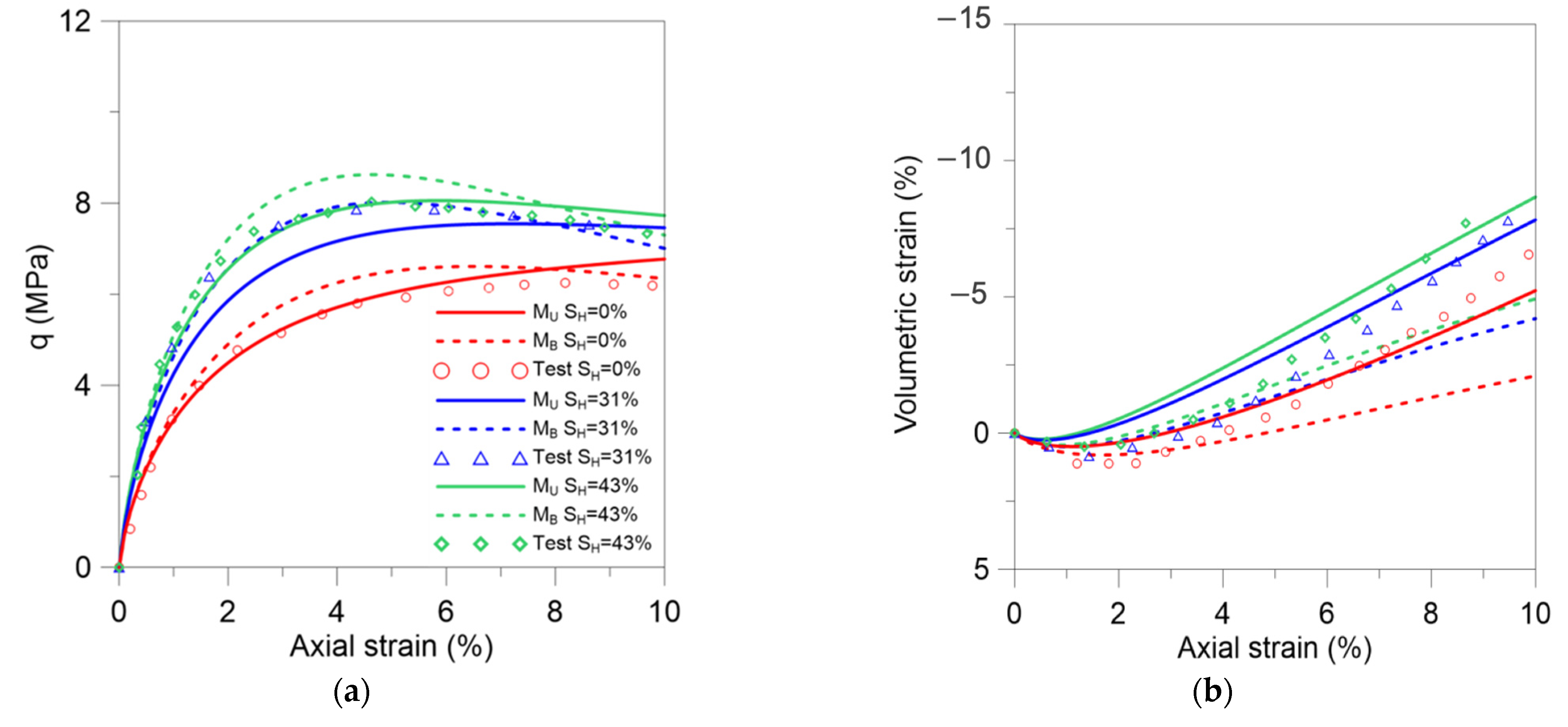
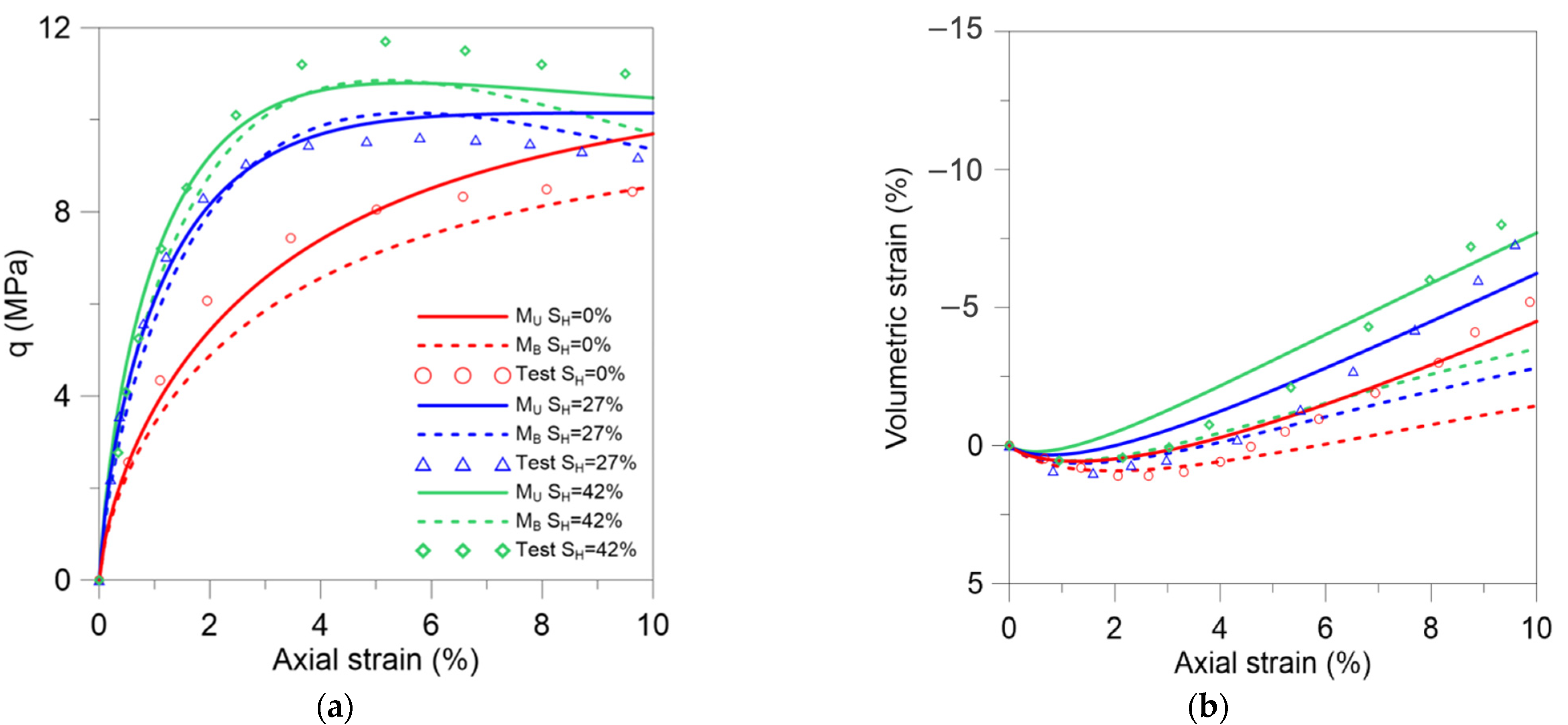
The first set of tests selected to validate the proposed model corresponds to the triaxial tests reported in Miyazaki et al. [82]. These tests were simulated in previous works using a model for MHBS based on the modified Cam-Clay model (e.g., Uchida et al. [64]) and the basic MHBS-HISS model, Gai and Sanchez [67]. These models were able to capture qualitatively well the overall behavior of the MHBS samples, but the high-dilatancy exhibited during shearing. The hydrate sediments were prepared in the lab using Toyoura sand at different hydrates saturations. The samples were then sheared at different confining stresses (3). Figure 5, Figure 6 and Figure 7 present the experimental results (symbols) of the tests sheared at 3 = 1 MPa (SH = 0%; SH = 34%; and SH = 41%), 3 = 2 MPa (SH = 0%; SH = 31%; and SH = 43%), and 3 = 3 MPa (SH = 0%, SH = 27%, and SH = 42%), respectively. These figures also present the modeling results obtained with the original MHBS-HISS model [67] (dash lines, identified as MB), and the upgraded model considering Equation (3) for the strain-hardening law (solid lines, identified as MU). The model parameters are listed in Table A1. Note that pc = 7.7 MPa, 12.1 MPa and 16.1 MPa were adopted for the cases associated with 3 = 1 MPa, 2 MPa, and 3 MPa, respectively.
In terms of deviatoric stress (i.e., Figure 5a, Figure 6a and Figure 7a), both constitutive models are able to reproduce quite satisfactorily the main trends observed in the tests, namely: increase of MHBS strength and stiffens with SH, a more marked post-peak softening behavior with the increase of SH, and increase of MHBS strength with the increase of confinement. The main difference between the two models is apparent when comparing the volumetric behavior (Figure 5b, Figure 6b and Figure 7b). The new model reproduces noticeably much better the large dilation observed in these tests, particularly for the MHBS samples with high SH. The new model also captures well the decrease in soil dilation with the confinement increase.
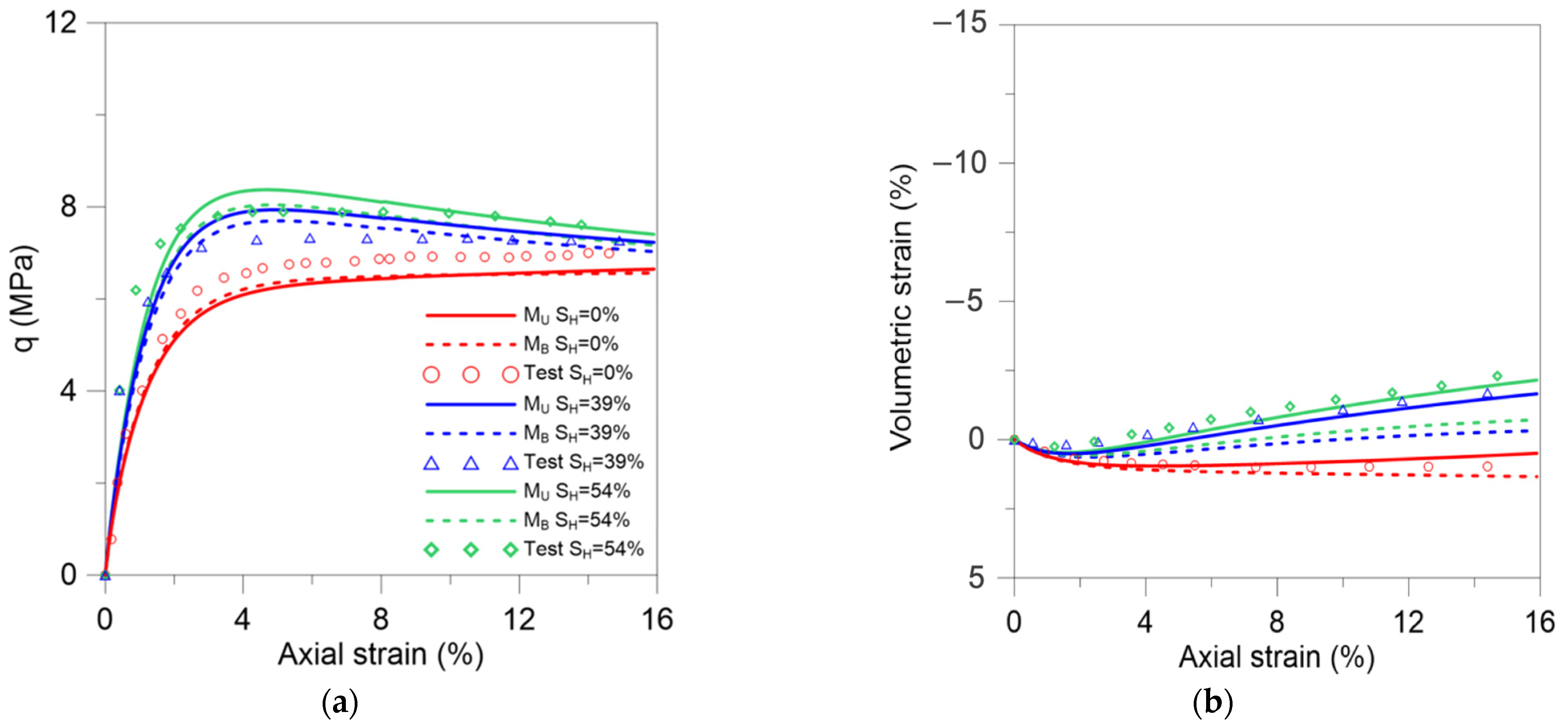
The second case analyzed in this section corresponds to the triaxial tests reported in Hyodo et al. [6]. The synthetic MHBS samples were based on Toyoura sand and prepared at three hydrate saturations: SH = 0%, SH = 39%, and SH = 54%. The samples were sheared at 3 = 3 MPa. We modeled these tests using both, the original MHBS-HISS model and the upgrade version proposed in this work. Table A2 lists the model parameters. As in the previous case, the effect of hydrate saturation on MHBS behavior is characterized by a marked influence of SH on material stiffens, strength (Figure 8a), and volumetric response (Figure 8b). It can be observed that the proposed model is able to reproduce more accurately the large dilation observed in these experiments and overcomes the shortcomings experienced by previous approaches to model this critical feature of MHBS behavior. These results suggest that the proposed model will be able to properly predict the sediment volume changes (with the associated settlements and ground subsidence) in engineering problems involving MHBS.
3.2. Model Application Considering the Effect of Temperature on MHBS Behavior
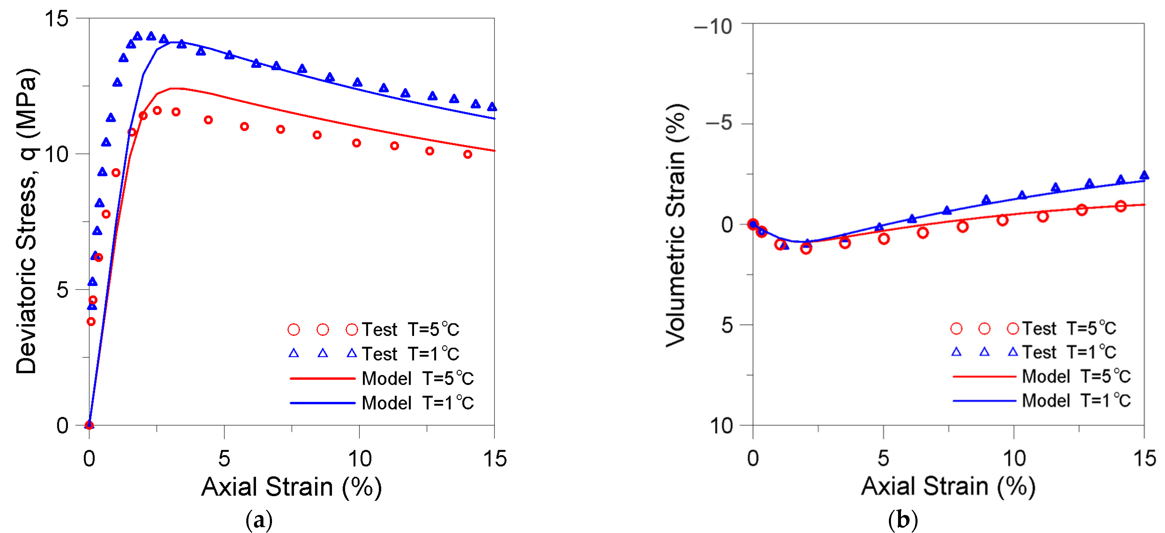
In this section we adopted the thermo-plastic model for MHBS introduced in Section 2.3 to simulate three cases reported in the literature. All the triaxial tests were conducted inside the hydrate stability zone at three constant temperatures. The first series of triaxial tests analyzed in this section were performed on synthetic MHBS samples prepared from Toyoura sand by Hyodo et al. [31]. The triaxial tests were conducted at two temperatures: T = 1 °C and T = 5 °C. The parameters adopted to model these tests are listed in Table A3. Figure 9a shows that the upgraded model (lines) agreed very well with the observed experimental behavior, reproducing the increase of strength with temperature (although, the model slightly underpredicted it at the lower temperature), as well as the post-peak behavior observed in the experiments (symbols). The model is also capable of properly capturing the effect of temperature on the volumetric behavior of MHBS including the increase of dilation with the decrease of temperature (Figure 9b).
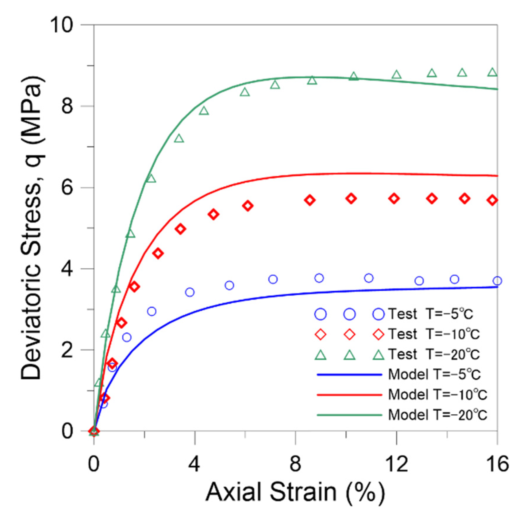
The second series of triaxial tests analyzed in this section correspond to the three synthetic MHBS samples based on kaolin clay reported in Li et al. [96]. The three tests were carried out at the same confining pressures (3 = 5 MPa), same hydrate saturation (SH = 30%), same loading rate, and they were shared at three constant temperatures, T = −5 °C, T = −10 °C, T = −20 °C. Table A4 lists the adopted parameters. The updated model captures well both the increase of strength and the change in material stiffness with temperature (Figure 10).
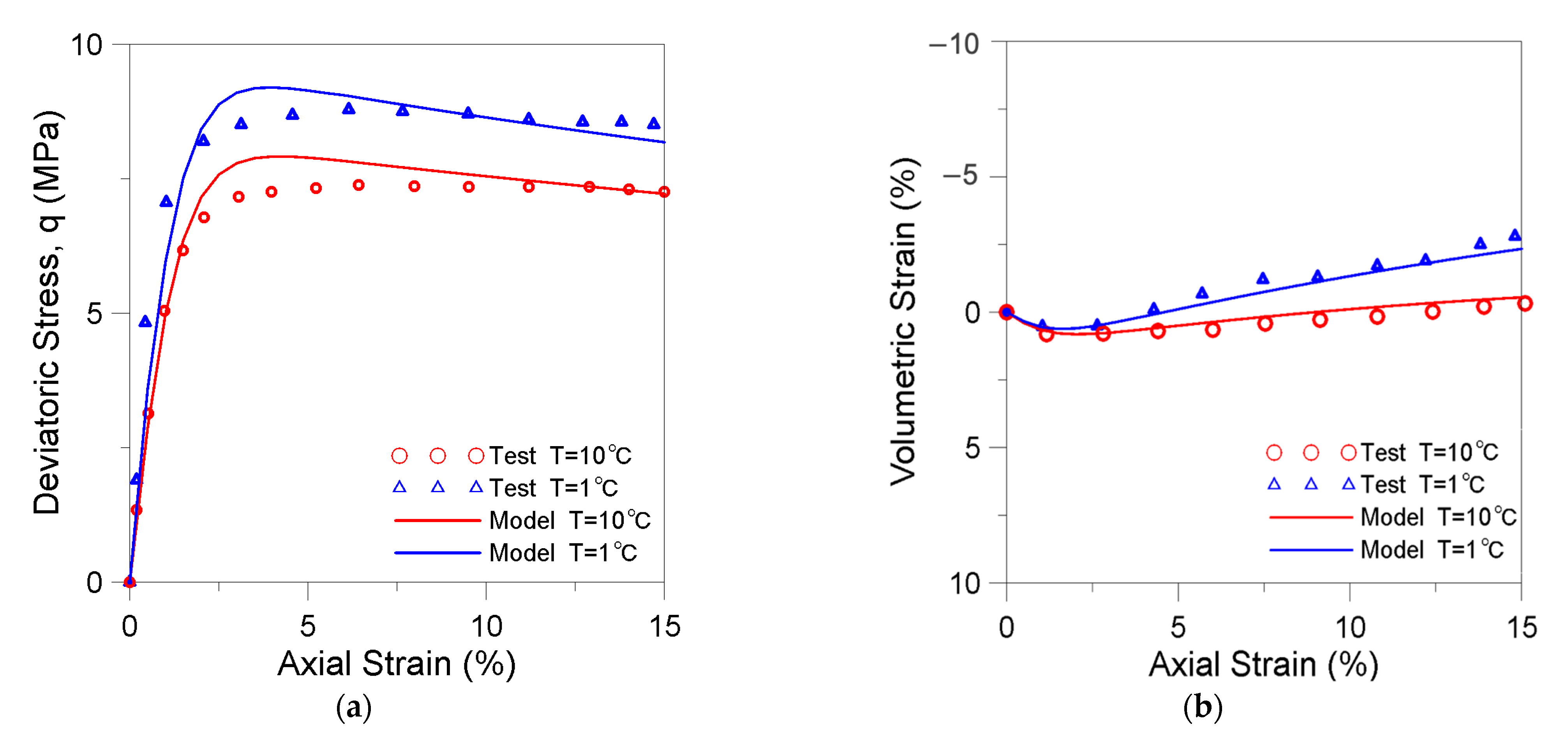
The last set of experiments analyzed in this section corresponds to the triaxial tests conducted by Hyodo et al. [6] on two MHBS Toyoura sand samples that were prepared at SH = 53.1% and SH = 51.6%, and sheared at T = 1 °C and at T = 10 °C, respectively. The two samples were tested at the same effective confining pressure (3′ = 3 MPa). Figure 11a,b present the experimental results together with the modeling outputs. Figure 11a shows that the model predicts very well, the impact of temperature on soil stiffness, strength, and post-peak behavior. The volumetric behavior of the MHBS (Figure 11b) at different temperatures is also well capture by the upgraded model. The adopted parameters are listed in Table A5.
3.3. Model Application Considering the Effect of Loading Rate on MHBS Behavior
To validate the capability of the upgraded model (Section 2.4) to deal with time-rate effects in MHBS we adopted two types of tests, namely, (a) drained triaxial tests conducted at different (constant) loading rates (LR), reported in Miyazaki et al. [33], and (b) drained triaxial experiments conducted at two loading rates during shearing, reported in Miyazaki et al. [33] and Yoneda et al. [41].
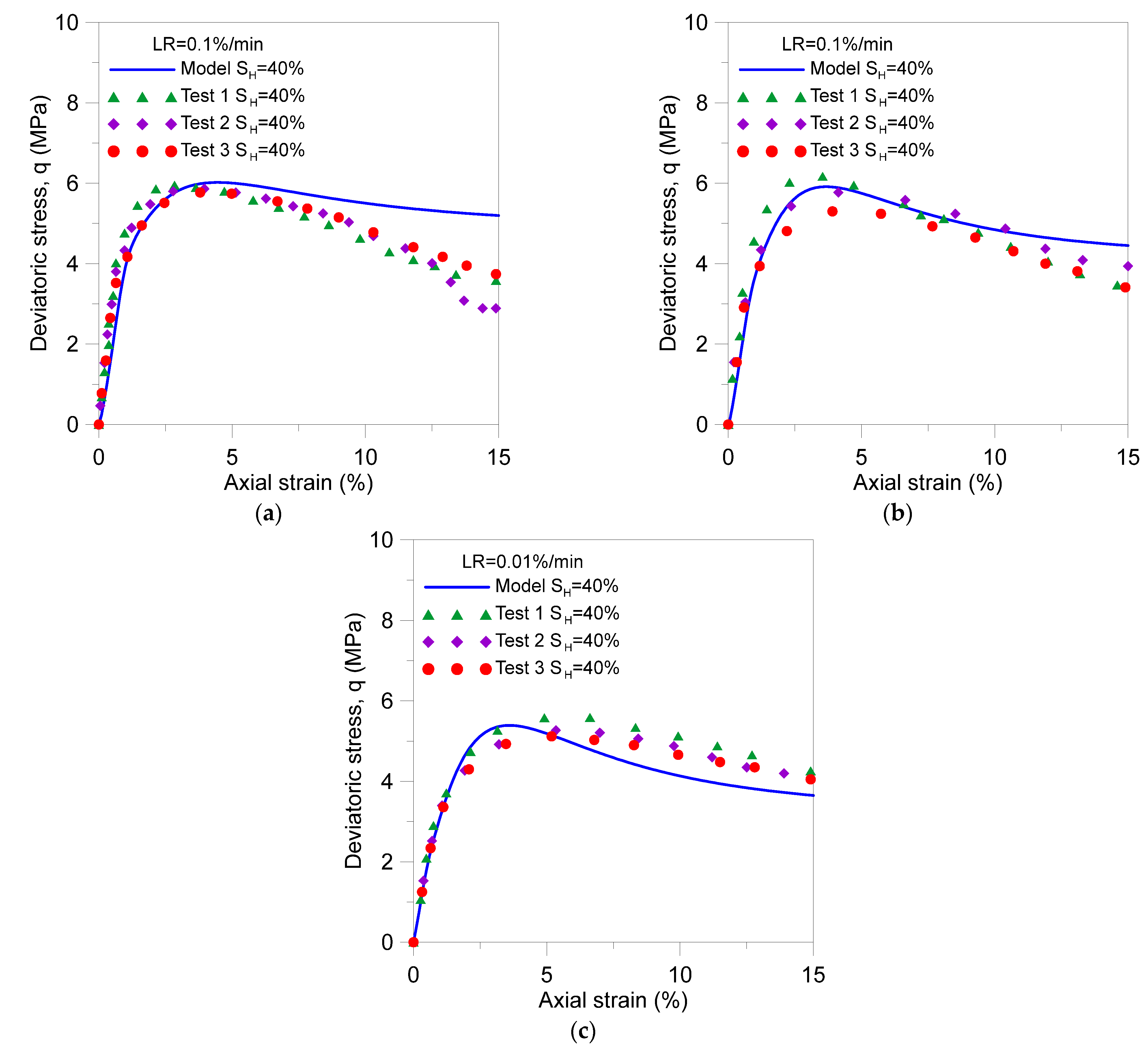
As for the set of tests at constant LR, the artificial MHBS samples were based on Toyoura sand and intended to have a target hydrate saturation SH~40%. Given the difficulties to form hydrate in experimental conditions and to determine its saturation, in the examined samples SH varies between 35~45%. Here we adopt a unique set of parameters (Table A6) to model all the experiments. Three loading rates were investigated, LR = 0.1%/min, LR = 0.05%/min, and LR = 0.01%/min. Three samples were tested per each experiment (i.e., per each SH and LR). Figure 12a–c presents the comparisons between the experimental (symbols) and modeling (lines) results for the tests conducted at LR = 0.1%/min, LR = 0.05%/min, and LR = 0.01%/min, respectively.
The proposed model agrees well with the overall observed behavior involving different loading rates and hydrates saturations. Particularly, it properly captures the increase in strength with the increase of LR observed in MHBS samples. It also reproduces well the softening behavior after the peak in the MHBS samples, particularly at the two lower loading rates. There are some slight differences between experiments and simulations in some tests, but the overall performance of the model is very satisfactory, particularly considering that despite the variations in the SH of the tested specimens, we adopted a unique set of parameters to model all the experiments.
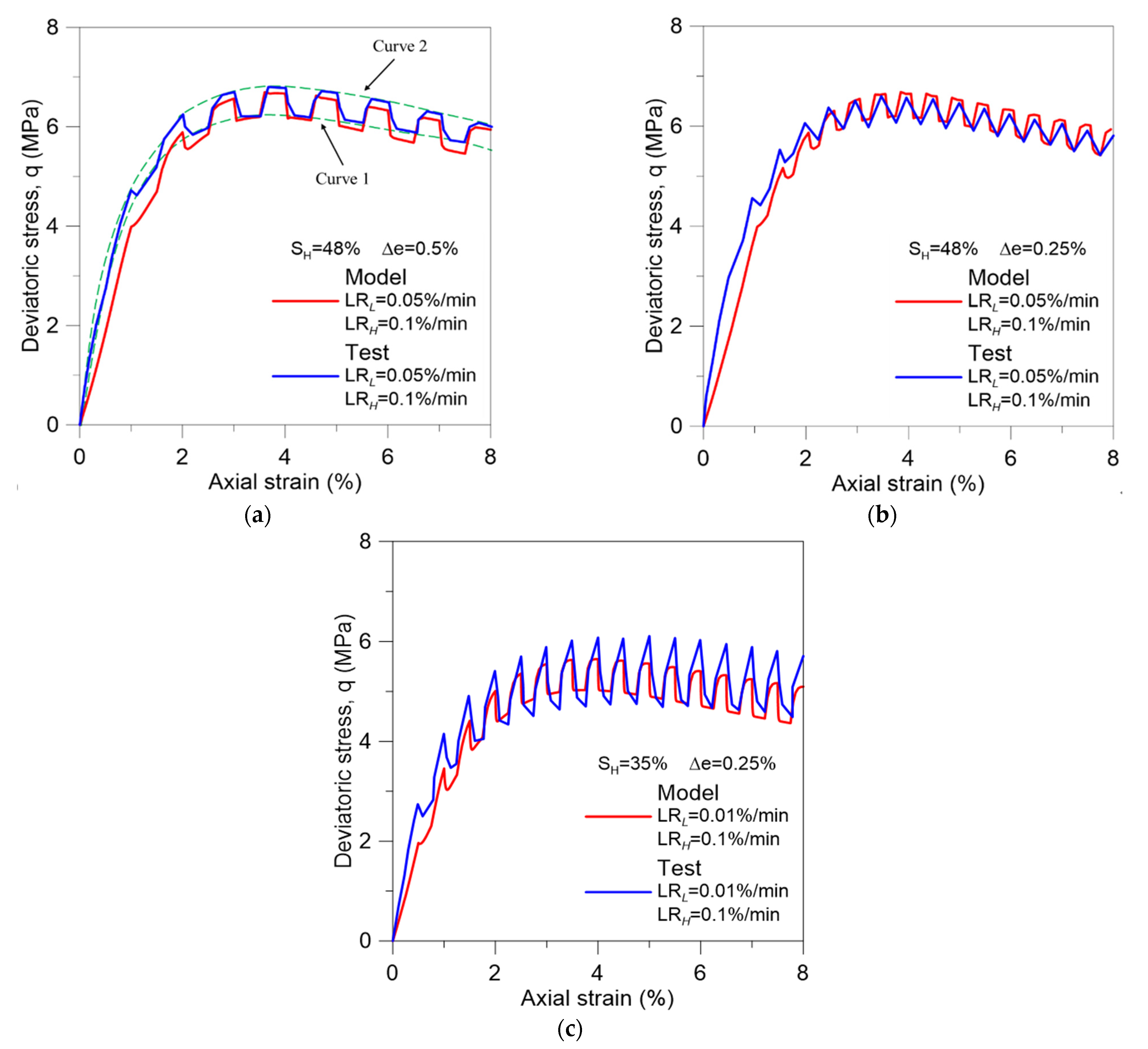
In the first set of tests at varying LR during shearing analyzed in this section the artificial MHBS samples were also based on Toyoura sand, as reported in Miyazaki et al. [33]. The three tests involve samples prepared at two hydrate saturations, namely, SH = 35% and SH = 48%. The tests considered different loading rates and different axial strain intervals (). This type of experiment generally contemplates the following test protocol: (i) preparation of the hydrate-sand or sand (SH = 0%) specimen by the water saturation method in the test apparatus, (ii) application of the loading at a low loading rate (LRL) until the axial strain reached a target value (e.g., 0.25%); (iii) modification of the loading rate to the high loading rate (LRH) until the target axial strain interval (i.e., until e.g., another 0.25% is reached). This sequence is repeated successively until the total axial strain is reached (i.e., until shear failure). The three tests were conducted at the same LRH = 0.1%/min but considering different low loading rates and axial strain intervals. In test (I) LRL was 0.05%/min, = 0.5%, and SH = 48% (Figure 13a); in test (II) LRL was 0.05%/min, = 0.25%, and SH = 48% (Figure 13b); and in test (III) LRL was 0.01%/min, = 0.25%, and SH = 35% (Figure 13c).
We modeled these tests following the same test protocol explained above. We adopted a unique set of parameters to simulate all the experiments, which are listed in Table A6. Figure 13a–c presents the tests (blue lines) and the numerical outputs in red lines. The two stress-strain curve envelops related to LRH (curve 2) and LRL (curve 1) are plotted using green dash lines in Figure 13a.
Test (III) (i.e., Figure 13c) exhibited a slightly lower strength that tests (I) (i.e., Figure 13a) and (II) (i.e., Figure 13b). This response was expected because in test (III) both SH and LRL were smaller than in tests (I) and (II). Comparing Figure 13b, c, one can conclude that (for the same ), the larger the difference between the LRH and LRL, the larger the difference between the deviatoric stresses associated with these loading rates. Comparing Figure 13a, b, we can see that (for the same loading rates and hydrate saturation), the change in does not significantly impact on the deviatoric stresses associated with the LRH and LRL. The proposed model is able to capture qualitatively well the main features of MHBS behavior discussed above. The results obtained with the viscoplastic model are also satisfactory in quantitative terms.
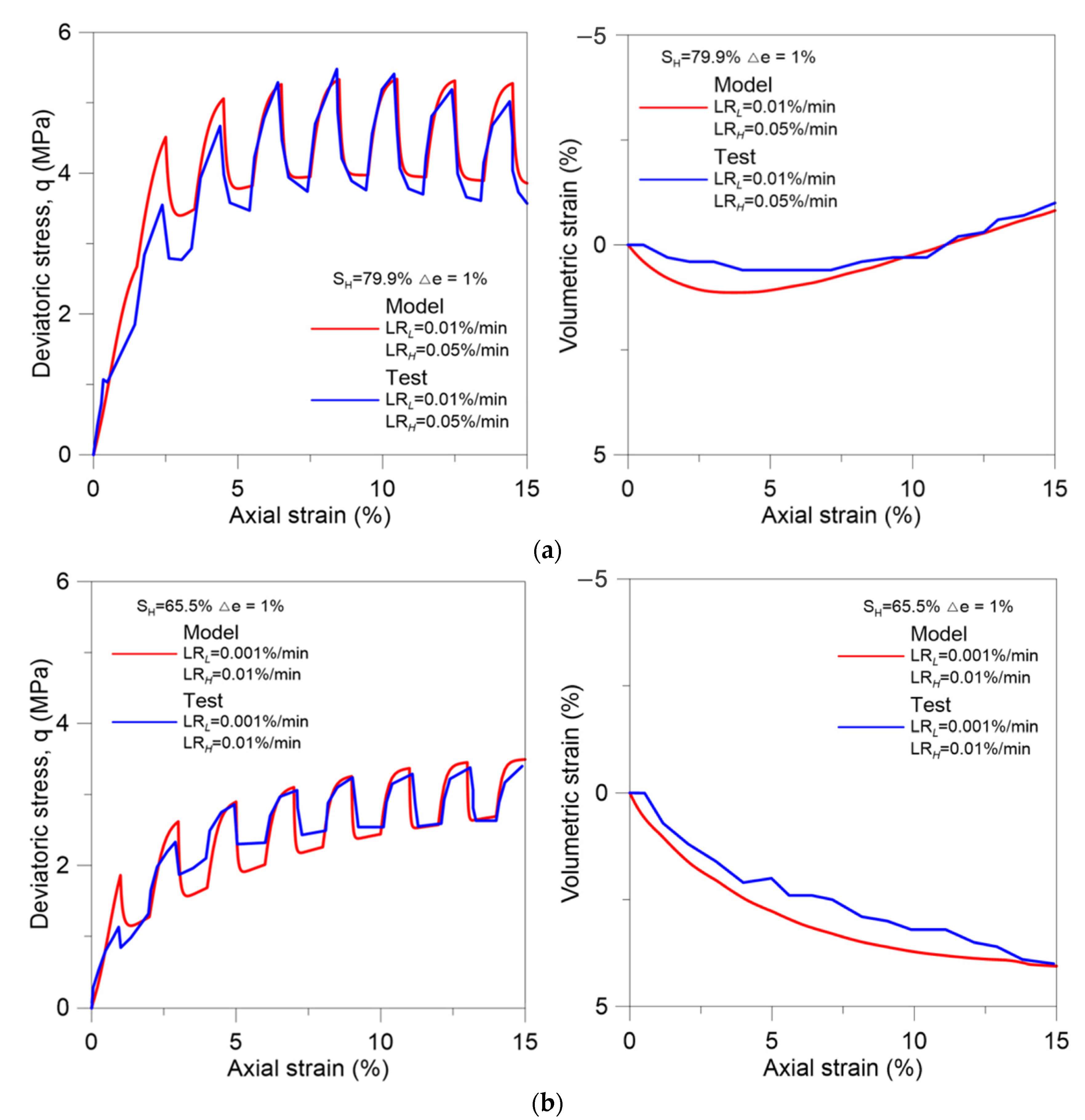
The final set of experiments analyzed in this section corresponds to the two drained compression triaxial tests conducted by Yoneda et al. [41] at varying LR involving natural samples from different boreholes (Borehole 16B-4P and Borehole 17C-9P). Both tests adopted the same axial strain interval ( = 1%), but in one of them LRL was 0.01%/min, LRH = 0.05%/min, and SH~80% (Figure 14a); and in the other test LRL was 0.001%/min, LRH = 0.01%/min, and SH~65% (Figure 14b).
In this case it is also apparent that the higher strength corresponds to the test conducted at the higher loading rate and on the specimen with the higher hydrate saturation (Figure 14a). A tendency to dilate was also observed in the first test that corresponds to the specimen with the higher SH (Figure 14b). The parameters adopted to model these two experiments are listed in Table A7. In addition, in this case, it can be observed that the model captures well the global behavior observed in these experiments, reproducing very satisfactorily both the stress developed at the different loading rates and the volumetric behavior displayed by these specimens during shearing. These are critical features of MHBS behavior that the proposed approach is able to properly reproduce, enabling a more reliable modeling of engineering problems involving this type of soil.
4. Conclusions
We upgraded a mechanical constitutive model for MHBS to account for features of this type of soil that are generally not well simulated by standard models. We selected an existing model that considers, amongst others factors, the effect of hydrate saturation on material stiffness, strength and pre-consolidation stress. We incorporated into the formulation three main new components: an enhanced hardening law (to capture the large dilatancy behavior observed in MHBS); a modified evolution law for the pre-consolidation pressure (to account for the effect of temperature on the sediment mechanical properties); and Perzyna’s concepts to include rate effect on the response of MHBS. We then validated the model using published data associated with the testing of methane hydrate bearing soils under different conditions. The proposed approach agreed well with the overall response observed in the selected experiments, demonstrating that the new model is able to successfully account for key features of MHBS behavior, such as, effect hydrate saturation and morphology, large dilatancy, thermal effects, and rates effects. These are key features of material behavior to properly model different engineering problems involving MHBS behavior, amongst others, wellbore geomechanical stability and seabed subsidence during methane production from hydrate bearing sediments reservoirs; and submarine landslides. Furthermore, as MHBS behavior engages strongly coupled THMC phenomena, where the mechanical behavior controls the changes in material porosity (with its direct impact on hydraulic permeability, fluids storage, thermal conductivity, and diffusion) a geomechanical constitutive able to predict the actual material behavior is instrumental to conduct reliable numerical simulations.
Author Contributions
Conceptualization, M.S.; methodology, M.S., L.O. and B.Z.; software, B.Z.; validation, B.Z. and M.S.; writing—original draft preparation, B.Z. and M.S.; writing—review and editing, L.O. and J.C.S.; supervision, M.S.; funding acquisition, M.S. and J.C.S. All authors have read and agreed to the published version of the manuscript.
Funding
We acknowledge the financial support from NETL (National Energy Technology Laboratory, DOE, USA, through Award No.: DE-FE0013889.
Institutional Review Board Statement
Not applicable.
Informed Consent Statement
Not applicable.
Data Availability Statement
Not applicable.
Acknowledgments
The authors thank Xuerui Gai for technical assistance and useful discussion.
Conflicts of Interest
The authors declare no conflict of interest. The funders had no role in the design of the study; in the collection, analyses, or interpretation of data; in the writing of the manuscript, or in the decision to publish the results.
Abbreviations
| SH | Hydrate saturation degree |
| , n | Model yield function parameter |
| p’ | Mean effective stress |
| q | Deviatoric stress |
| M | Slope of critical line in the q—p’ space |
| pc | Mean pre-consolidation effective stress |
| pd | Strength increment with presence of hydrates |
| R | Evolution variable |
| Volumetric plastic strain | |
| Deviatoric plastic strain | |
| e | Void ratio |
| κ | Slope for elastic isotropic paths in the e—(ln)p’ plane |
| λ | Slope for plastic isotropic paths in the e—(ln)p’ plane |
| Ds | Nova parameter |
| pc0 | Pre-consolidation mean stress at T0 |
| T0 | Reference temperature |
| rT | Temperature effect parameter on the pre-consolidation mean stress |
| Scalar function | |
| FS | Yield surface (YS) function for the static yield surface |
| FD | Yield surface function for the dynamic yield surface |
| GD | Plastic potential function at predicted stress point |
| p’D | Mean effective stress at predicted stress point |
| qD | Deviatoric stress at predicted stress point |
| Fluidity | |
| Cauchy’s stress tensor of predicted stress point | |
| f | Over-stress index |
| f0 | Reference value in flow function |
| nf | Model parameter in flow function |
| pcS | Mean pre-consolidation effective stress for static YS |
| pdS | Strength increment with presence of hydrates for static YS |
| RS | Evolution variable for static YS |
| Viscoplastic strain associated with the dynamic yield surface | |
| Axial strain interval | |
| K’ | Bulk modulus |
| Plastic multiplier | |
| Parameters accounting for hydrate contribution | |
| Damage variable | |
| Parameter controlling rate of mechanical damage | |
| Subloading parameter |
Appendix A
Additional Equations for HISS-MHBS Model and parameter estimation.
It is assumed that the elastic volumetric strains increment depends on p’ increment through the following law:
It is also assumed that deviatoric elastic strains and stresses are relate through the shear modulus (Gs).
For the sake of the simplicity, an associated flow rule is assumed in this paper (i.e., coincide with the plastic potential G), so the flow rule can be written as:
where ∧ is the plastic multiplier and σ’ is the effective stress tensor.
The following evolution law was adopted to model the increase of strength observed in hydrate bearing sediments [67]:
where α and β are model parameters that accounts for the hydrate contribution to the hardening law; χ is a damage variable which can range between 0 (when the hydrates do not provide any bonding between soil particles) and 1 (when the hydrates induce the maximum bonding). The degradation of bonding during yielding is considered as follows [67]:
where μ controls the rate of mechanical damage.
The evolution of the sub-loading surface ratio is given by [67]:
where |dεp|dεp is the norm of the (total) plastic strain vector and is a sub-loading parameter related to plastic deformations developed inside the initial yield surface.
Most of the model parameters can be determined directly from experiments, but some others require a back-analysis analysis based on fitting experimental data. The parameters associated with the elastoplastic model to describe the hydrate-free soil (i.e., κ, λ, Gs, po, and M) can be determined following the procedure typically adopted in soils mechanics to estimate critical state model constants, as described in [67]. The main parameters that control the effect of hydrates (i.e., hydrate saturation and morphology) on sediment behavior are α β μ and the variable χ. These parameters are mainly related to the increase of preconsolidation pressure and sediment strength in MHBS. β and μ consider the effect of SH on HBS behavior (i.e., for a given hydrate morphology), and the parameter α can be used to account for the effect of pore habit (i.e., for a given SH). The parameter μ also controls the rate of mechanical damage. We assume that the rate of mechanical damage increases with SH, and that the rate of damage is higher for cementing morphology than for pore-filling. These parameters are generally indirectly calibrated from experiments [67].
Appendix B

| Properties | Upgraded Model MU | Basic Model MB |
|---|---|---|
| M | 1.28 | 1.28 |
| λ | 0.2 | 0.2 |
| κ | 0.004 | 0.004 |
| n | 1.3 | 1.3 |
| a | 3 | 3 |
| γ | −1/9 | −1/5 |
| α | 35 | 20 |
| β | 1 | 1 |
| μ | 7 | 7 |
| υ | 0.1 | 0.1 |
| Ds | 0.8 | 0.0 |
Table A2.
Parameters adopted for Model Validation in Figure 8.
Table A2.
Parameters adopted for Model Validation in Figure 8.
| Properties | Upgraded Model MU | Basic Model MB |
|---|---|---|
| M | 1.28 | 1.28 |
| λ | 0.24 | 0.24 |
| κ | 0.005 | 0.005 |
| pc (MPa) | 9.6 | 9.6 |
| n | 0.95 | 0.95 |
| a | 3 | 3 |
| γ | −1/10 | −1/10 |
| α | 8 | 6 |
| β | 0.7 | 0.7 |
| μ | 4.5 | 4.5 |
| υ | 0.35 | 0.35 |
| Ds | 0.1 | 0.0 |
Table A3.
Parameters adopted for simulation in Figure 9.
Table A3.
Parameters adopted for simulation in Figure 9.
| Parameter | Value |
|---|---|
| M | 1.25 |
| λ | 0.25 |
| κ | 0.015 |
| pc (MPa) | 3 |
| n | 1 |
| a | 2 |
| γ | −1/9 |
| α | 20 |
| β | 0.5 |
| μ | 5 |
| υ | 0.15 |
Table A4.
Parameters adopted for simulation in Figure 10.
Table A4.
Parameters adopted for simulation in Figure 10.
| Parameter | Value |
|---|---|
| M | 1.2 |
| λ | 0.5 |
| κ | 0.02 |
| pc (MPa) | 5 |
| n | 1 |
| a | 6 |
| γ | −1/9 |
| α | 15 |
| β | 1.2 |
| μ | 1 |
| υ | 0.15 |
Table A5.
Parameters adopted for simulation in Figure 11.
Table A5.
Parameters adopted for simulation in Figure 11.
| Parameter | Value |
|---|---|
| M | 1.25 |
| λ | 0.25 |
| κ | 0.015 |
| pc (MPa) | 3 |
| n | 1 |
| a | 3 |
| γ | −1/9 |
| α | 20 |
| β | 1 |
| μ | 1 |
| υ | 0.15 |
| Parameter | Value |
|---|---|
| M | 1.22 |
| λ | 0.2 |
| κ | 0.017 |
| pc (MPa) | 9 |
| n | 1 |
| a | 5 |
| γ | −1/9 |
| α | 20 |
| β | 1 |
| μ | 20 |
| υ | 0.2 |
| γf | 5 × 10⁻⁶ |
| nf | 1 |
Table A7.
Model parameters adopted for Case 3 in Figure 14.
Table A7.
Model parameters adopted for Case 3 in Figure 14.
| Parameter | Borehole 16B-4P | Borehole 17C-9P |
|---|---|---|
| M | 1.2 | 1.2 |
| λ | 0.28 | 0.28 |
| κ | 0.025 | 0.025 |
| pc (MPa) | 10 | 6.8 |
| n | 1 | 1 |
| a | 5 | 4.3 |
| γ | −1/12 | −1/12 |
| α | 10 | 10 |
| β | 10 | 10 |
| μ | 5 | 5 |
| υ | 0.2 | 0.2 |
| γf | 2 × 10⁻⁶ | 2 × 10⁻⁶ |
| nf | 1 | 1 |
References
- Soga, K.; Lee, S.L.; Ng, M.Y.A.; Klar, A. Characterisation and engineering properties of methane hydrate soils. Charact. Eng. Prop. Nat. Soils 2006, 3, 2591–2642. [Google Scholar]
- De La Fuente, M.; Vaunat, J.; Marín-Moreno, H. Modelling Methane Hydrate Saturation in Pores: Capillary Inhibition Effects. Energies 2021, 14, 5627. [Google Scholar] [CrossRef]
- Le, T.X.; Rodts, S.; Hautemayou, D.; Aimedieu, P.; Bornert, M.; Chabot, B.; Tang, A.M. Kinetics of methane hydrate formation and dissociation in sand sediment. Geomech. Energy Environ. 2020, 23, 100103. [Google Scholar] [CrossRef] [Green Version]
- Choi, J.H.; Lin, J.S.; Dai, S.; Lei, L.; Seol, Y. Triaxial compression of hydrate-bearing sediments undergoing hydrate dissociation by depressurization. Geomech. Energy Environ. 2020, 23, 100187. [Google Scholar] [CrossRef]
- Zhou, M.; Soga, K.; Yamamoto, K.; Huang, H. Geomechanical responses during depressurization of hydrate-bearing sediment formation over a long methane gas production period. Geomech. Energy Environ. 2020, 23, 100111. [Google Scholar] [CrossRef]
- Hyodo, M.; Yoneda, J.; Yoshimoto, N.; Nakata, Y. Mechanical and dissociation properties of methane hydrate-bearing sand in deep seabed. Soils Found. 2013, 53, 299–314. [Google Scholar] [CrossRef] [Green Version]
- Teymouri, M.; Sánchez, M.; Santamarina, J.C. A Pseudo-Kinetic Model to Simulate Phase Changes in Hydrate Bearing Sediments. Mar. Pet. Geol. 2020, 120, 104519. [Google Scholar] [CrossRef]
- Ruppel, C.D.; Kessler, J.D. The interaction of climate change and methane hydrate. Rev. Geophys. 2017, 55, 126–168. [Google Scholar] [CrossRef]
- Makogon, Y.F.; Holditch, S.A.; Makogon, T.Y. Natural gas-hydrates—A potential energy source for the 21st Century. J. Petrol. Sci. Eng. 2007, 56, 14–31. [Google Scholar] [CrossRef]
- Dai, S.; Sanchez, M. Geomechanics for Energy and the Environment [GETE]—Special Issue: “Challenges of gas production from hydrate-bearing sediments”. Geomech. Energy Environ. 2020, 23, 100189. [Google Scholar] [CrossRef]
- Liu, Z.Q.; Lu, Y.X.; Cheng, J.H.; Han, Q.; Hu, Z.; Wang, L. Geomechanics involved in gas hydrate recovery. Chin. J. Chem. Eng. 2019, 27, 2099–2106. [Google Scholar] [CrossRef]
- Zhou, S.S.; Yang, L.; Lv, X.; Xue, K.; Zhao, J.; Liu, Y.; Yang, S. Fine sand migration in hydrate-bearing sediments and median grain size ratio optimization of gravel pack. J. Nat. Gas Sci. Eng. 2021, 88, 103809. [Google Scholar] [CrossRef]
- Marín-Moreno, H.; Giustiniani, M.; Tinivella, U. The potential response of the hydrate reservoir in the South Shetland Margin, Antarctic Peninsula, to ocean warming over the 21st century. Polar Res. 2015, 34, 27443. [Google Scholar] [CrossRef] [Green Version]
- Elliott, S.; Reagan, M.; Moridis, G.; Smith, P.C. Geochemistry of clathrate-derived methane in Arctic Ocean waters. Geophys. Res. Lett. 2010, 37, L12607. [Google Scholar] [CrossRef] [Green Version]
- Li, X.S.; Xu, C.G.; Zhang, Y.; Ruan, X.K.; Li, G.; Wang, Y. Investigation into gas production from natural gas hydrate: A review. Appl. Energy 2016, 172, 286–322. [Google Scholar] [CrossRef] [Green Version]
- Gambelli, A.M.; Presciutti, A.; Rossi, F. Review on the characteristics and advantages related to the use of flue-gas as CO2/N2 mixture for gas hydrate production. Fluid Phase Equilibria 2021, 541, 113077. [Google Scholar] [CrossRef]
- Luo, T.T.; Li, Y.H.; Madhusudhan, B.N.; Zhao, J.F.; Song, Y.C. Comparative analysis of the consolidation and shear behaviors of CH4 and CO2 hydrate-bearing silty sediments. J. Nat. Gas Sci. Eng. 2020, 75, 103157. [Google Scholar] [CrossRef]
- Masui, A.; Haneda, H.; Ogata, Y.; Aoki, K. Effects of methane hydrate formation on shear strength of synthetic methane hydrate sediments. In Proceedings of the International Offshore and Polar Engineering Conference, Seoul, Korea, 19-24 June 2005; pp. 364–369. [Google Scholar]
- Santamarina, J.; Ruppel, C. The impact of hydrate saturation on the mechanical, electrical, and thermal properties of hydrate-bearing sand, silts, and clay. Geophys. Charact. Gas Hydrates 2010, 26, 373–384. [Google Scholar]
- Hyodo, M.; Wu, Y.; Nakashima, K.; Kajiyama, S.; Nakata, Y. Influence of fines content on the mechanical behavior of methane hydrate-bearing sediments. J. Geophys. Res. Solid Earth 2017, 122, 7511–7524. [Google Scholar] [CrossRef]
- Wang, L.; Li, Y.; Shen, S.; Liu, W.; Sun, X.; Liu, Y.; Zhao, J. Mechanical behaviors of gas-hydrate bearing clayey sediments of the South China Sea. Environ. Geotech. 2020, 40, 1–13. [Google Scholar]
- Dong, L.; Li, Y.; Liao, H.; Liu, C.; Chen, Q.; Hu, G.; Liu, L.; Meng, Q. Strength estimation for hydrate-bearing sediments based on triaxial shearing tests. J. Petrol. Sci. Eng. 2020, 184, 106478. [Google Scholar] [CrossRef]
- Song, Y.; Zhu, Y.; Liu, W.; Li, Y.; Lu, Y.; Shen, Z. The effects of methane hydrate dissociation at different temperatures on the stability of porous sediments. J. Pet. Sci. Eng. 2016, 147, 77–86. [Google Scholar] [CrossRef]
- Jia, J.; Liang, Y.; Tsuji, T.; Murata, S.; Matsuoka, T. Elasticity and stability of clathrate hydrate: Role of guest molecule motions. Sci. Rep. 2017, 7, 1290. [Google Scholar] [CrossRef] [PubMed] [Green Version]
- Wang, L.; Liu, W.; Li, Y.; Wu, P.; Shen, S. Mechanical behaviors of methane hydrate-bearing sediments using montmorillonite clay. Energy Procedia 2019, 158, 5281–5286. [Google Scholar] [CrossRef]
- Shen, S.; Li, Y.H.; Sun, X.; Wang, L.; Song, L.C. Mechanical properties of methane hydrate-bearing sandy sediments under various temperatures and pore pressures. J. Pet. Sci. Eng. 2022, 208, 109474. [Google Scholar] [CrossRef]
- Le, T.X.; Aimedieu, P.; Bornert, M.; Chabot, B.; Rodts, S.; Tang, A.M. Effect of temperature cycle on mechanical properties of methane hydrate-bearing sediment. Soils Found. 2019, 59, 814–827. [Google Scholar] [CrossRef]
- Yu, F.; Song, Y.; Liu, W.; Li, Y.; Lam, W. Analyses of stress strain behavior and constitutive model of artificial methane hydrate. J. Petrol. Sci. Eng. 2011, 77, 183–188. [Google Scholar] [CrossRef]
- Freij-Ayoub, R.; Tan, C.; Clennell, B.; Tohidi, B.; Yang, J. A wellbore stability model for hydrate bearing sediments. J. Pet. Sci. Eng. 2007, 57, 209–220. [Google Scholar] [CrossRef]
- Sun, J.X.; Ning, F.L.; Lei, H.W.; Gai, X.R.; Sánchez, M.; Lu, J.; Li, Y.L.; Liu, L.L.; Liu, C.L.; Wu, N.Y.; et al. Wellbore stability analysis during drilling through marine gas hydratebearing sediments in Shenhu area: A case study. J. Pet. Sci. Eng. 2018, 170, 345–367. [Google Scholar] [CrossRef]
- Hyodo, M.; Li, Y.; Yoneda, J.; Nakata, Y.; Yoshimoto, N.; Nishimura, A.; Song, Y. Mechanical behavior of gas-saturated methane hydrate-bearing sediments. J. Geophys. Res. 2013, 118, 5185–5194. [Google Scholar] [CrossRef] [Green Version]
- Miyazaki, K.; Masui, A.; Yamaguchi, T.; Sakamoto, Y.; Haneda, H.; Ogata, Y.; Aoki, K. Strain-rate Dependency of Peak and Residual Strength of Sediment Containing Synthetic Methane Hydrate in Triaxial Compression Test. In Proceedings of the Nineteenth International Offshore and Polar Engineering Conference, Osaka, Japan, 21–26 July 2009. ISOPE-I-09-344. [Google Scholar]
- Miyazaki, K.; Masui, A.; Aoki, K.; Sakamoto, Y.; Yamaguchi, T.; Okubo, S. Strain-Rate Dependence of Triaxial Compressive Strength of Artificial Methane-Hydrate-Bearing Sediment. Int. J. Offshore Polar Eng. 2010, 20, 256–264. [Google Scholar]
- Miyazaki, K.; Yamaguchi, T.; Sakamoto, Y.; Aoki, K. Time-dependent behaviors of methane-hydrate bearing sediments in triaxial compression test. Jpn. Comm. Rock Mech. 2010, 7, 43–48. [Google Scholar]
- Miyazaki, K.; Tenma, N.; Sakamoto, Y.; Yamaguchi, T.; Okubo, S. Effects of Methane Hydrate Saturation and Confining Pressure on Strain-Rate Dependence of Artificial Methane-Hydrate-Bearing Sediment in Triaxial Compression Test. Int. J. Offshore Polar Eng. 2012, 22, 148–154. [Google Scholar]
- Miyazaki, K.; Tenma, N.; Yamaguchi, T. Relationship between Creep Property and Loading-Rate Dependence of Strength of Artificial Methane-Hydrate-Bearing Toyoura Sand under Triaxial Compression. Energies 2017, 10, 1466. [Google Scholar] [CrossRef] [Green Version]
- Miyazaki, K.; Tenma, N.; Endo, Y.; Yamaguchi, T. A viscoelastic constitutive equation for methane-hydrate-bearing sand. In Proceedings of the Eighth Asian Rock Mechanics Symposium, Sapporo, Japan, 14–16 October 2014. [Google Scholar]
- Kimoto, S.; Oka, F.; Fushita, T. A chemo-thermo-mechanically coupled analysis of ground deformation induced by gas hydrate dissociation. Int. J. Mech. Sci. 2010, 52, 365–376. [Google Scholar] [CrossRef]
- Akaki, T.; Kimoto, S.; Oka, F. Chemo-thermo-mechanically coupled seismic analysis of methane hydrate-bearing sediments during a predicted Nankai Trough Earthquake. Int. J. Numer. Anal. Methods GeoMech. 2016, 40, 2207–2237. [Google Scholar] [CrossRef]
- Deusner, C.; Gupta, S.; Xie, X.G.; Leung, Y.F.; Uchida, S.; Kossel, E.; Haeckel, M. Strain rate dependent hardening-softening characteristics of gas hydrate-bearing sediments. Geochem. Geophys. Geosyst. 2019, 20, 4885–4905. [Google Scholar] [CrossRef]
- Yoneda, J.; Oshima, M.; Kida, M.; Kato, A.; Konno, Y.; Jin, Y.; Jang, J.; Waite, W.; Kumar, P.; Tenma, N. Pressure core based onshore laboratory analysis on mechanical properties of hydrate-bearing sediments recovered during India’s National Gas Hydrate Program Expedition (NGHP) 02. Mar. Pet. Geol. 2019, 108, 482–501. [Google Scholar] [CrossRef]
- Priest, J.A.; Hayley, J.L. Strength of laboratory synthesized hydrate-bearing sands and their relationship to natural hydrate-bearing sediments. J. Geophys. Res. 2019, 124, 12556–12575. [Google Scholar] [CrossRef]
- Yun, T.S.; Santamarina, C.J.; Ruppel, C. Mechanical properties of sand, silt, and clay containing tetrahydrofuran hydrate. J. Geophys. Res. Solid Earth 2007, 112, B04106. [Google Scholar] [CrossRef]
- Ahmadi, G.; Ji, C.; Smith, D.H. Numerical solution for natural gas production from methane hydrate dissociation. J. Pet. Sci. Eng. 2004, 41, 269–285. [Google Scholar] [CrossRef]
- White, M.D.; McGrail, B.P. STOMP-HYD: A new numerical simulator for analysis of methane hydrate production from geologic formations. In Proceedings of the 2nd International Symposium on Gas Hydrate Technology at the 43rd Coordinating Committee for Geoscience Programmes in East and Southeast Asia (CCOP) Annual Session, Bangkok, Thailand, 29 October–3 November 2006; pp. 77–86. [Google Scholar]
- Rutqvist, J.; Moridis, G. Numerical Studies on the Geomechanical Stability of Hydrate-Bearing Sediments. SPE J. 2009, 14, 267–282. [Google Scholar] [CrossRef]
- Fang, H.L. A fully coupled thermo-hydro-mechanical model for methane hydrate reservoir simulations. In Proceedings of the International Symposium on Geoenvironmental Engineering, Hangzhou, China, 8–10 September 2009. [Google Scholar]
- Cheng, Y.; Li, L.; Yuan, Z.; Wu, L.; Mahmood, S. Finite element simulation for fluid solid coupling effects on depressurization induced gas production from gas hydrates reservoirs. J. Nat. Gas Sci. Eng. 2013, 10, 1–7. [Google Scholar] [CrossRef]
- Moridis, G.J. TOUGH+HYDRATE v1.2 User’s Manual: A Code for the Simulation of System Behavior in Hydrate Bearing Geologic Media; Lawrence Berkeley National Laboratory: Berkeley, CA, USA, 2014; LBNL-0149E-Rev. [Google Scholar]
- De La Fuente, M.; Vaunat, J.; Marín-Moreno, H. Thermo-Hydro-Mechanical Coupled Modeling of Methane Hydrate-Bearing Sediments: Formulation and Application. Energies 2018, 12, 2178. [Google Scholar] [CrossRef] [Green Version]
- Sánchez, M.; Santamarina, J.C.; Teymouri, M.; Gai, X. Coupled numerical modeling of gas hydrate bearing sediments: From laboratory to field-scale analyses. J. Geophys. Res.-Solid Earth 2018, 123, 10326–10348. [Google Scholar] [CrossRef] [Green Version]
- White, M.; Kneafsey, T.; Seol, Y.; Waite, W.; Uchida, S.; Lin, J.S.; Myshakin, E.M.; Gai, X.; Gupta, S.; Reagan, M.; et al. An international code comparison study on coupled thermal, hydrologic and geomechanical processes of natural gas hydrate-bearing sediments. Mar. Pet. Geol. 2022, 120, 104519. [Google Scholar] [CrossRef]
- De La Fuente, M.; Vaunat, J.; Marín-Moreno, H. Consolidation of gas hydrate-bearing sediments with hydrate dissociation. E3S Web Conf. 2021, 205, 11007. [Google Scholar] [CrossRef]
- Duncan, J.M.; Chang, C.Y. Nonlinear analysis of stress and strain in soils. J. Soil Mech. Found Div. 1970, 96, 1629–1653. [Google Scholar] [CrossRef]
- Yu, F.; Song, Y.; Li, Y.; Liu, W.; Lam, W. Analysis of stress-strain behavior and constitutive relation of methane Hydrate-Bearing sediments with various Porosity. Int. J. Offshore Polar Eng. 2011, 21, 316–322. [Google Scholar]
- Yan, C.; Cheng, Y.; Li, M.; Han, Z.; Zhang, H.; Li, Q.; Teng, F.; Ding, J. Mechanical experiments and constitutive model of natural gas hydrate reservoirs. Int. J. Hydrogen Energy 2017, 42, 19810–19818. [Google Scholar] [CrossRef]
- Miyazaki, K.; Aoki, K.; Tenma, N.; Sakamoto, Y.; Yamaguchi, T. Application of nonlinear elastic constitutive model to analysis of artificial methane-hydrate-bearing sediment sample. In Proceedings of the Ninth ISOPE Ocean Mining Symposium, Maui, HI, USA, 19-24 June 2011. [Google Scholar]
- Li, Y.; Song, Y.; Liu, W.; Yu, F.; Wang, R. A new strength criterion and constitutive model of gas hydrate-bearing sediments under high confining pressures. J. Petrol. Sci. Eng. 2013, 109, 45–50. [Google Scholar] [CrossRef]
- Klar, A.; Soga, K.; Ng, M.Y.A. Coupled deformation–flow analysis for methane hydrate extraction. Géotechnique 2010, 60, 765–776. [Google Scholar] [CrossRef]
- Klar, A.; Uchida, S.; Soga, K.; Yamamoto, K. Explicitly coupled thermal flow mechanical formulation for gas-hydrate sediments. SPE J. 2013, 18, 196–206. [Google Scholar] [CrossRef]
- Pinkert, S. Rowe’s stress-dilatancy theory for hydrate-bearing sand. Int. J. GeoMech. 2017, 17, 06016008. [Google Scholar] [CrossRef]
- Roscoe, K.H.; Schofield, A.N.; Wroth, C.P. On the yielding of soils. Géotechnique 1958, 8, 22–53. [Google Scholar] [CrossRef]
- Sultan, N.; Garziglia, S. Geomechanical constitutive modelling of gas-hydrate-bearing sediments. In Proceedings of the 7th International Conference on Gas Hydrates (ICGH 2011), Edinburgh, Scotland, UK, 17–21 July 2011. [Google Scholar]
- Uchida, S.; Xie, X.G.; Leung, Y.F. Role of critical state framework in understanding geomechanical behavior of methane hydrate-bearing sediments. J. Geophys. Res. Solid Earth 2016, 121, 5580–5595. [Google Scholar] [CrossRef]
- Shen, J.; Chiu, C.F.; Ng, C.W.W.; Lei, G.H.; Xu, J. A state-dependent critical state model for methane hydrate-bearing sand. Comput. Geotech. 2016, 75, 1–11. [Google Scholar] [CrossRef]
- Yan, R.; Wei, C. A constitutive model for gas hydrate-bearing sediments considering hydrate occurring habits. Rock Soil Mech. 2017, 38, 10–18. [Google Scholar]
- Gai, X.; Sanchez, M. A geomechanical model for gas hydrate-bearing sediments. J. Environ. Geotech. 2017, 4, 143–156. [Google Scholar] [CrossRef]
- Sanchez, M.; Gai, X.; Santamarina, C.J. A constitutive mechanical model for gas hydrate bearing sediments incorporating inelastic mechanisms. Comput. Geotech. 2017, 84, 28–46. [Google Scholar] [CrossRef] [Green Version]
- Zhou, M.; Soga, K.; Yamamoto, K. Upscaled anisotropic methane hydrate critical state model for turbidite hydrate-bearing sediments at east Nankai Trough. J. Geophys. Res. Solid Earth 2018, 123, 6277–6298. [Google Scholar] [CrossRef]
- Sun, X.; Wang, L.; Luo, H.; Song, Y.; Li, Y. Numerical modeling for the mechanical behavior of marine gas hydrate-bearing sediments during hydrate production by depressurization. J. Petrol. Sci. Eng. 2019, 177, 971–982. [Google Scholar] [CrossRef]
- De La Fuente, M.; Vaunat, J.; Marín-Moreno, H. A densification mechanism to model the mechanical effect of methane hydrates in sandy sediments. Int. J. Numer. Anal. Methods Geomech. 2020, 44, 782–802. [Google Scholar] [CrossRef]
- Ng, C.W.W.; Baghbanrezvan, S.; Kadlicek, T.; Zhou, C. A state-dependent constitutive model for methane hydrate-bearing sediments inside the stability region. Géotechnique 2020, 70, 1094–1108. [Google Scholar] [CrossRef]
- Pinyol, N.M.; Vaunat, J.; Alonso, E.E. A constitutive model for soft clayey rocks that includes weathering effects. Géotechnique 2007, 57, 137–151. [Google Scholar] [CrossRef] [Green Version]
- Perzyna, P. Fundamental problems in viscoplasticity. Rec. Adv. Appl. Mech. 1966, 9, 243–377. [Google Scholar]
- Dai, S.; Lee, C.; Santamarina, J.C. Formation history and physical properties of sediments from the Mount Elbert gas hydrate stratigraphic test well, Alaska North Slope. Mar. Pet. Geol. 2011, 28, 427–438. [Google Scholar] [CrossRef]
- Waite, W.F.; Santamarina, J.C.; Cortes, D.D.; Dugan, B.; Espinoza, D.N.; Germaine, J.; Jang, J.; Jung, J.W.; Kneafsey, T.J.; Shin, H.; et al. Physical properties of hydrate-bearing sediments. Rev. Geophys. 2009, 47, 1–38. [Google Scholar] [CrossRef]
- Desai, C.S.; Somasundaram, S.; Frantziskonis, G. A hierarchical approach for constitutive modelling of geologic materials. Int. J. Numer. Anal. Methods Geomech. 1986, 10, 225–257. [Google Scholar] [CrossRef]
- Desai, C.S. Letter to editor single surface yield and potential function plasticity models: A review. Comput. Geotech. 1989, 7, 319–333. [Google Scholar] [CrossRef]
- Uchida, S.; Soga, K.; Yamamoto, K. Critical state soil constitutive model for methane hydrate soil. J. Geophys. Res. Solid Earth 2012, 117, 1–13. [Google Scholar] [CrossRef]
- Hashiguchi, K. Subloading surface model in unconventional plasticity. Int. J. Solids Struct. 1989, 25, 917–945. [Google Scholar] [CrossRef]
- Hashiguchi, K.; Chen, Z.P. Elastoplastic constitutive equation of soils with the subloading surface and the rotational hardening. Int. J. Numer. Anal. Methods Geomech. 1998, 22, 197–227. [Google Scholar] [CrossRef]
- Miyazaki, K.; Masui, A.; Sakamoto, Y.; Aoki, K.; Tenma, N.; Yamaguchi, T. Triaxial compressive properties of artificial methane-hydrate-bearing sediment. J. Geophys. Res. 2011, 116, 1–11. [Google Scholar] [CrossRef]
- Nova, R. Development of Elastoplastic Strain Hardening Models of Soil Behavior. Degrad. Instab. Geomater. Int. Cent. Mech. Sci. 2004, 461, 35–76. [Google Scholar]
- McCartney, J.; Sánchez, M.; Tomac, I. Energy Geotechnics: Advances in Subsurface Energy Recovery, Storage, Exchange, and Waste Management. Comput. Geotech. 2016, 75, 244–256. [Google Scholar] [CrossRef] [Green Version]
- Cekerevac, C.; Laloui, L. Experimental study of thermal effects on the mechanical behavior of a clay. Int. J. Numer. Anal. Meth. Geomech. 2004, 28, 209–228. [Google Scholar] [CrossRef]
- Loveridge, F.; McCartney, J.; Narsilio, G.; Sánchez, M. Energy Geostructures: A Review of Analysis Approaches, in-situ Testing and Model Scale Experiments. Geomech. Energy Environ. 2020, 22, 100173. [Google Scholar] [CrossRef] [Green Version]
- Sultan, N.; Delage, P.; Cui, Y.J. Temperature effects on the volume change behaviour of Boom clay. Eng. Geol. 2002, 64, 135–145. [Google Scholar] [CrossRef]
- Garitte, B.; Gens, A.; Vaunat, J.; Armand, G. Thermal Conductivity of Argillaceous Rocks: Determination Methodology Using In Situ Heating Tests. Rock Mech. Rock Eng. 2014, 47, 111–129. [Google Scholar] [CrossRef] [Green Version]
- Sánchez, M.; Pomaro, B.; Gens, A. Coupled THM Analysis of a Full-Scale Test for High-Level Nuclear Waste and Spent Fuel Disposal Under Actual Repository Conditions During 18 Years of Operation. Géotechnique 2022. [Google Scholar] [CrossRef]
- Campanella, R.G.; Mitchell, J.K. Influence of temperature variations on soil behavior. J. Soil Mech Found Div. 1968, 94, 709–734. [Google Scholar] [CrossRef]
- Hueckel, T.; Baldi, G. Thermoplasticity of saturated clays: Experimental constitutive study. J Geotech Eng. 1990, 116, 1778–1796. [Google Scholar] [CrossRef]
- Gens, A. Constitutive laws. In Modern Issues in Non-saturated Soils; Springer: Berlin, Germany, 1995; pp. 129–158. [Google Scholar]
- Laloui, L.; Cekerevac, C. Thermo-plasticity of clays: An isotropic yield mechanism. Comput Geotech. 2003, 30, 649–660. [Google Scholar] [CrossRef]
- Liu, W.; Luo, T.; Li, Y.; Song, Y.; Zhu, Y.; Liu, Y.; Zhao, J.; Wu, Z.; Xu, X. Experimental study on the mechanical properties of sediments containing CH4 and CO2 hydrate mixtures. J. Nat. Gas Sci. Eng. 2016, 32, 20–27. [Google Scholar] [CrossRef]
- Luo, T.; Li, Y.; Liu, W.; Sun, X.; Shen, S. Experimental Study on the Mechanical Properties of CH4 and CO2 Hydrate Remodeling Cores in Qilian Mountain. Energies 2017, 10, 2078. [Google Scholar] [CrossRef] [Green Version]
- Li, Y.; Song, Y.; Yu, F.; Liu, W.; Zhao, J. Experimental Study on Mechanical Properties of Gas Hydrate-Bearing Sediments Using Kaolin Clay. China Ocean Eng. 2011, 25, 113–122. [Google Scholar] [CrossRef]
- Mitchell, J.K.; Campanella, R.G.; Singh, A. Soil Creep as a Rate Process. J. Soil Mech. Found. Div. 1968, 94, 231–253. [Google Scholar] [CrossRef]
- Kuhn, M.R.; Mitchell, J.K. New Perspectives on Soil Creep. J. Geotech. Eng. 1993, 119, 507–524. [Google Scholar] [CrossRef]
- Feda, J. Creep of Soils: And Related Phenomena; Elsevier Science: Amsterdam, The Netherlands, 1992. [Google Scholar]
- Sorensen, K.K.; Baudet, B.B.; Simpson, B. Influence of structure on the time-dependent behaviour of a stiff sedimentary clay. Géotechnique 2007, 57, 113–124. [Google Scholar] [CrossRef] [Green Version]
- Benedetto, H.D.; Tatsuoka, F.; Ishihara, M. Time-dependent shear deformation characteristics of sand and their constitutive modelling. Soils Found 2002, 42, 1–22. [Google Scholar] [CrossRef] [Green Version]
- Laloui, L.; Leroueil, S.; Chalindar, S. Modelling the combined effect of strain rate and temperature on one-dimensional compression of soils. Can. Geotech. J. 2008, 12, 1765–1777. [Google Scholar] [CrossRef]
- Graham, J.; Crooks, J.H.A.; Bell, A.L. Time effects on the stress-strain behaviour of natural soft clays. Géotechnique 1983, 33, 327–340. [Google Scholar] [CrossRef]
- Adachi, T.; Oka, F.; Koike, M. An elasto-viscoplastic constitutive model with strain-softening for soft sedimentary rocks. Soil Found. 2005, 45, 125–133. [Google Scholar] [CrossRef] [Green Version]
- Qiao, Y.; Ferrari, A.; Laloui, L.; Ding, W. Nonstationary flow surface theory for modeling the viscoplastic behaviors of soils. Comput. Geotech. 2016, 76, 105–119. [Google Scholar] [CrossRef]
- Qiao, Y.; Ding, W. ACMEG-TVP: A thermoviscoplastic constitutive model for geomaterials. Comput. Geotech. 2017, 81, 98–111. [Google Scholar] [CrossRef]
- Adachi, T.; Oka, F. Constitutive equations for normally consolidated clay based on elasto-viscoplasticity. Soils Found 1982, 22, 57–70. [Google Scholar] [CrossRef] [Green Version]
- Modaressi, H.; Laloui, L. A thermo-viscoplastic constitutive model for clays. Int. J. Numer. Anal. Meth. Geomech. 1997, 21, 313–335. [Google Scholar] [CrossRef]
- Freitas, T.M.B.; Potts, D.M.; Zdravkovic, L. A time dependent constitutive model for soils with isotach viscosity. Comput. Geotech. 2011, 38, 809–820. [Google Scholar] [CrossRef]
- Sivasithamparam, N.; Karstunen, M.; Bonnier, P. Modelling creep behaviour of anisotropic soft soils. Comput. Geotech. 2015, 69, 46–57. [Google Scholar] [CrossRef] [Green Version]
- Hinchberger, S.D.; Rowe, R.K. Evaluation of the predictive ability of two elastic–viscoplastic constitutive models. Can. Geotech. J. 2005, 42, 1675–1694. [Google Scholar] [CrossRef]
- Yin, Z.Y.; Chang, C.S.; Karstunen, M.; Hicher, P.Y. An anisotropic elastic–viscoplastic model for soft clays. Int. J. Solids Struct. 2010, 47, 665–677. [Google Scholar] [CrossRef] [Green Version]
- Heeres, O.M.; Suiker, A.S.J.; Borst, R. A comparison between the Perzyna viscoplastic model and the consistency viscoplastic model. Eur. J. Mech. A/Solids 2002, 21, 1–12. [Google Scholar] [CrossRef]
- Desai, C.S.; Zhang, D. Viscoplastic models for geologic materials with generalized flow rule. Int. J. Num. Anal. Meth. Geomech. 1987, 11, 603–620. [Google Scholar] [CrossRef]
Figure 1.
Different types of morphology for methane hydrate bearing sediments [1]. (a) Cementation; (b) pore filling; (c) supporting matrix.
Figure 1.
Different types of morphology for methane hydrate bearing sediments [1]. (a) Cementation; (b) pore filling; (c) supporting matrix.

Figure 2.
Yield surfaces adopted to model the mechanical behavior of MHBS.

Figure 3.
Schematic representation of the effect of temperature on sediment yield surface.

Figure 4.
Yield surfaces considered when modeling rate-effects.

Figure 5.
Modeling the tests reported in Miyazaki et al. [82] at 3 = 1 MPa. (a) Deviatoric stress versus axial strains; (b) volumetric strains versus axial strains.
Figure 5.
Modeling the tests reported in Miyazaki et al. [82] at 3 = 1 MPa. (a) Deviatoric stress versus axial strains; (b) volumetric strains versus axial strains.

Figure 6.
Modeling the tests reported in Miyazaki et al. [82] at 3 = 2 MPa. (a) Deviatoric stress versus axial strains; (b) volumetric strains versus axial strains.
Figure 6.
Modeling the tests reported in Miyazaki et al. [82] at 3 = 2 MPa. (a) Deviatoric stress versus axial strains; (b) volumetric strains versus axial strains.

Figure 7.
Modeling the tests reported in Miyazaki et al. [82] at 3 = 3 MPa. (a) deviatoric stress versus axial strains; (b) volumetric strains versus axial strains.
Figure 7.
Modeling the tests reported in Miyazaki et al. [82] at 3 = 3 MPa. (a) deviatoric stress versus axial strains; (b) volumetric strains versus axial strains.

Figure 8.
Modeling the tests reported in Hyodo et al. [6] at 3 = 3 MPa. (a) Deviatoric stress versus axial strains; (b) volumetric strain versus axial strains.
Figure 8.
Modeling the tests reported in Hyodo et al. [6] at 3 = 3 MPa. (a) Deviatoric stress versus axial strains; (b) volumetric strain versus axial strains.

Figure 9.
Modeling the tests reported in Hyodo et al. [31] at different temperatures. (a) Deviatoric stress versus axial strains; (b) volumetric strain versus axial strains.
Figure 9.
Modeling the tests reported in Hyodo et al. [31] at different temperatures. (a) Deviatoric stress versus axial strains; (b) volumetric strain versus axial strains.

Figure 10.
Modeling the tests reported in Li et al. [96] at different temperatures, deviatoric stress versus axial strains.
Figure 10.
Modeling the tests reported in Li et al. [96] at different temperatures, deviatoric stress versus axial strains.

Figure 11.
Modeling the tests reported in Hyodo et al. [6] at different temperatures. (a) Deviatoric stress versus axial strains; (b) volumetric strain versus axial strains.
Figure 11.
Modeling the tests reported in Hyodo et al. [6] at different temperatures. (a) Deviatoric stress versus axial strains; (b) volumetric strain versus axial strains.

Figure 12.
Modeling the tests reported in Miyazaki et al. [33]. (a) Constant loading rate LR = 0.1%/min; (b) constant LR = 0.1%/min; and (c) constant LR = 0.1%/min.
Figure 12.
Modeling the tests reported in Miyazaki et al. [33]. (a) Constant loading rate LR = 0.1%/min; (b) constant LR = 0.1%/min; and (c) constant LR = 0.1%/min.

Figure 13.
Case 2 considering effect of loading rate on MHBS behavior Miyazaki et al. [33]. (a) Test (I); (b) test (II); (c) test (III).
Figure 13.
Case 2 considering effect of loading rate on MHBS behavior Miyazaki et al. [33]. (a) Test (I); (b) test (II); (c) test (III).

Figure 14.
Case 3 considering effect of loading rate on MHBS behavior Yoneda et al. [41]. (a) ‘Specimen one’ from Borehole 16B-4P; (b) ‘Specimen two’ from Borehole 17C-9P.
Figure 14.
Case 3 considering effect of loading rate on MHBS behavior Yoneda et al. [41]. (a) ‘Specimen one’ from Borehole 16B-4P; (b) ‘Specimen two’ from Borehole 17C-9P.

Publisher’s Note: MDPI stays neutral with regard to jurisdictional claims in published maps and institutional affiliations. |
© 2022 by the authors. Licensee MDPI, Basel, Switzerland. This article is an open access article distributed under the terms and conditions of the Creative Commons Attribution (CC BY) license (https://creativecommons.org/licenses/by/4.0/).
Share and Cite
MDPI and ACS Style
Zhou, B.; Sanchez, M.; Oldecop, L.; Santamarina, J.C. A Geomechanical Model for Gas Hydrate Bearing Sediments Incorporating High Dilatancy, Temperature, and Rate Effects. Energies 2022, 15, 4280. https://doi.org/10.3390/en15124280
AMA Style
Zhou B, Sanchez M, Oldecop L, Santamarina JC. A Geomechanical Model for Gas Hydrate Bearing Sediments Incorporating High Dilatancy, Temperature, and Rate Effects. Energies. 2022; 15(12):4280. https://doi.org/10.3390/en15124280
Chicago/Turabian StyleZhou, Bohan, Marcelo Sanchez, Luciano Oldecop, and J. Carlos Santamarina. 2022. "A Geomechanical Model for Gas Hydrate Bearing Sediments Incorporating High Dilatancy, Temperature, and Rate Effects" Energies 15, no. 12: 4280. https://doi.org/10.3390/en15124280
Note that from the first issue of 2016, this journal uses article numbers instead of page numbers. See further details here.