
Gasification of Solid Fuels (Coal, Biomass and MSW): Overview, Challenges and Mitigation Strategies


1
Department of Mechanical and Product Design Engineering, Swinburne University of Technology, Hawthorn, VIC 3122, Australia
2
Department of Chemical Engineering, Monash University, Clayton, VIC 3800, Australia
*
Author to whom correspondence should be addressed.
Energies 2022, 15(12), 4444; https://doi.org/10.3390/en15124444
Submission received: 8 May 2022
/
Revised: 11 June 2022
/
Accepted: 17 June 2022
/
Published: 18 June 2022
(This article belongs to the Special Issue Recent Progress in Bio-Energy with Carbon Capture and Storage)
Abstract
:Currently, hydrogen energy is the most promising energy vector, while gasification is one of the major routes for its production. However, gasification suffers from various issues, including slower carbon conversion, poor syngas quality, lower heating value and higher emissions. Multiple factors affect gasification performance, such as the selection of gasifiers, feedstock’s physicochemical properties and operating conditions. In this review, the status of gasification, key gasifier technologies and the effect of solid-fuel (i.e., coal, biomass and MSW) properties on gasification performance are reviewed critically. Based on the current review, the co-gasification of coal, biomass and solid waste, along with a partial utilisation of CO2 as a reactant, are suggested. Furthermore, a technological breakthrough in carbon capture and sequestration is needed to make it industrially viable.
1. Introduction
In 2020, the total energy consumption in the world was 560 exajoules (EJ) [1], which is forecasted to be 712 EJ by 2040, according to the International Energy Agency’s stated policies scenario [2]. Coal currently meets around 27% of the world energy demand [1], which is projected to be about 20% in 2040 [2]. Biomass and municipal solid waste (MSW) are gaining importance rapidly due to their role in global decarbonisation [3,4]. In 2018, global energy consumption from biomass was 55.6 EJ, out of which 85% was supplied by solid biomass, 7% from liquid biofuels, 5% from municipal and industrial solid waste and 3% from biogases [5]. The world MSW generation is about 2.0 billion tonnes (BT) [6], which is forecasted to be 3.4 BT in 2050 [7].
Global fossil-fuel-related CO2 emissions increased from 9.38 BT in 1960 to 34.8 BT in 2020 [8]. The CO2 gas emission by sectors includes electricity and heat generation: 37%, transportation: 25%, industry: 23%, building: 9%, agriculture, forestry, and other land use: 6% [2]. In 2020, 37% of the CO2 emission was caused by coal consumption [8].
Along with other greenhouse gasses, coal-fired power plants typically emit 1.0 kg of CO2 per kW of electricity production [9]. Hence, advanced technologies are required to reduce emissions and increase thermal efficiency simultaneously. One such technology is gasification, which can efficiently convert solid carbonaceous fuels such as coal, biomass and MSW into syngas [10]. Syngas generated from gasification is subsequently utilised for power production or valuable chemical synthesis.
A detailed review considering the fundamental challenges, including mitigating strategies, for coal, biomass and MSW gasification is limited in the literature. Hence, this article has reviewed various aspects of those issues and proposes possible solutions to overcome those challenges.
2. Gasification Technologies
Gasification is the key technology for the cleaner conversion of solid fuels such as coal, biomass and MSW, which have long been used under different names around the globe [11,12,13,14,15,16,17]. Gasification technology is primarily divided into three major groups: fixed bed, fluidised bed and entrained-flow gasifier [18]. The fundamental aspect of each category is readily available in a large amount of literature. Therefore, this review summarises a key comparison of those technologies in Table 1. However, interested readers are referred to the following articles for details on those theories and fundamental physics: fixed bed gasifier [19,20], fluidised bed gasifier [20,21,22,23,24,25,26] and entrained flow gasifier [18,19,20,27]. Moreover, due to their importance and widespread industrial application, a comparison of commercial entrained flow gasifiers is reported in Table 2, while schematic views of those gasifiers are in Figure 1.
Ash and Slag Characteristics for Entrained-Flow Gasifier
During gasification, inorganic minerals of coal, biomass and MSW generate ash [38]. One of the key features of entrained-flow gasifier is the transformation of ash into molten slag under high-temperature operation. Typically, entrained-flow gasifiers are slagging types. Slagging is one of the greatest challenges for gasification performance as slagging increases the system cost considerably. Furthermore, it is also a barrier to the continuous operation of the gasifier due to the blockage of slag-removal devices, pressure drop and gasifier load reduction [19,39]. Moreover, high-temperature ash slag is accountable for damaging the expensive refractory lining of entrained-flow gasifiers. The steps for the deposition/penetration of slag in the gasifier tube are as follows: coal/biomass > char > ash > molten ash > liquid slag ⟷ solid slag [19].
Therefore, it is crucial to understand the characteristics of ash and slag for the fuels to be used in an entrained-flow gasifier. One of the important properties of understanding the characteristics of ash is ash fusion temperature (AFT) [40]. Several studies [39,40,41] present correlations built between the AFT and different properties such as mineral compositions, thermodynamics and ionic potential to predict the AFT. Recently, Li et al. [40] investigated AFT based on the average ionic potential for ten different types of coal collected from different deposits in China. The predicted correlation was AFT (°C) = 509.12 + 17.98 , where . The term represents mole fraction of Al2O3, CaO, FeO and MgO, which sum up to be 100%, whereas is the ionic potential of Fe2+ (26.3 nm−1), Mg2+ (30.8 nm−1), Ca2+ (20.2 nm−1) and Al3+ (60.0 nm−1) [41].
Song et al. [38] reported that the AFT decreases with increasing CaO up to the concentration of 30%, above which increasing the CaO leads to an increase in the AFT. The result was attributed to the subliquidus phase transformation from anorthite to the gehlenite phase, increasing CaO by over 30%. The flow behaviour of ash and slag primarily depends on the viscosity, which is affected by the thermochemical properties and crystalline structure of ash/slag. Oh et al. [42] demonstrated the effect of crystalline structure on the ash viscosity. Numerous studies investigated the impact of chemical composition on ash viscosity under various operating conditions [43,44,45]. Table 3 summarises the studies carried out for ash and slag behaviour analysis.
3. Current Status of Syngas Production from Gasification
The primary gasification product is syngas, used for various applications directly or after downstream treatment. Syngas obtained from gasification is cleaned before use in subsequent applications, such as hydrogen production, methanol synthesis, liquid-fuel synthesis, power generation, etc. [33,34]. Some available syngas treatment and purification techniques include water–gas shift reaction, methanation, membrane adjustment, acid gas removal, pressure swing adjustment and cryogenic separation [50]. On the other hand, various types of feedstock are used for gasification, such as coal, biomass, waste, petcoke and natural gas.
This section outlines the current status of gasification technologies based on the application, gasifier type, feedstock and status of plants worldwide. Table 4 summarises the world gasification plants and their production capacity. Globally, 44% of the syngas plants are under operation; 27% are under development; and the rest, 29%, are planned [51].
According to Table 5, syngas is predominantly used to produce chemicals with 45%; followed by 30% for gaseous fuels; 4% for industrial gases; 15% for liquid fuels; and the rest 6% for power generation [51].
Various fuels are used to produce syngas, of which coal plays the dominant role, accounting for 84%, while the shares of natural gas, petcoke and petroleum are about 5% each [51]. The production of syngas from renewable biomass is negligible, with a share of less than 1.0%. However, biomass is a promising feedstock that may play a significant role in the foreseeable future due to the restriction on the use of coal in some countries. Table 6 illustrates the worldwide application of syngas.
4. Properties of Coal, Biomass and MSW
The following sections outline different properties of coal and biomass affecting gasification performance.
4.1. Chemical Properties of Coal, Biomass and MSW
4.1.1. Chemical Properties of Coal
The chemical composition of coal is complex, consisting of organic and inorganic compounds. Up to 76 of the 90 naturally found elements listed in the periodic table can be found in coal, although most are in trace amounts [52]. The main elements present in the complex organic compounds of coal are C, H, N, S and O. On the other hand, more than 120 inorganic minerals can be found in coal, out of which 33 are common in most coal samples, and only eight are high enough to be considered major [52,53]. Table 7 shows the proximate and ultimate data for coal from different origins, whereas Table 8 shows the mineral content of some bituminous coal, which is studied for pyrolysis and gasification studies.

Table 7.
The proximate (wt.%) and ultimate (wt.%) analyses of coals from different origins.
| Origin/Reference | M | VM | FC | Ash | C | H | N | S | O | LHV (MJ/kg) |
|---|---|---|---|---|---|---|---|---|---|---|
| Chilean Sub-bituminous [54] | 14.3 | 34.6 | 35.8 | 15.3 | 52.4 | 3.6 | 0.8 | 0.2 | 13.4 | 18.9 |
| Spanish Alcorisa Lignite [54] | 11.1 | 38.6 | 39.0 | 11.3 | 54.7 | 4.1 | 0.4 | 8.1 | 10.3 | 20.8 |
| Kentucky, USA [13] | - | 39.1 | 50.7 | 8.3 | 81.4 | 5.6 | 1.7 | 3.3 | 7.94 | - |
| Illinois No. 6 bituminons, [55] | 8.5 | 36.0 | 44.8 | 10.7 | 69.3 | 5.0 | 1.1 | 3.5 | 9.3 | 26.3 |
| India (Tirap) [56] | 4.30 | 32.2 | 55.7 | 7.7 | - | - | - | 1.3 | - | 27.6 |
| Chines bituminons coal [57] | 1.66 | 34.3 | 48.4 | 15.5 | 55.3 | 2.1 | 0.8 | 0.4 | 5.3 | - |
| Chines Datong coal [58] | 3.2 | 25.7 | 57.3 | 13.7 | 82.7 | 5.0 | 0.8 | 2.4 | 8.9 | 26.5 |
| South African bituminous coal [59] | 3.5 | 25.5 | 55.3 | 15.7 | 66.3 | 3.6 | 1.8 | 0.5 | 8.6 | 24.9 |
| Taiheiyo bituminons coal, Japan [60] | 5.3 | 46.7 | 35.8 | 12.1 | 77.6 | 6.5 | 1.1 | 0.2 | 13.9 | 27.4 |
| Shenhua bituminous coal, China [61] | 5.51 | 32.2 | 54.48 | 7.81 | 70.5 | 4.8 | 1.0 | 0.7 | 9.58 | 26.3 |
| Victorian brown coal (Loy Yang) [62] | 11.1 | 48.2 | - | 8.0 | 50.1 | 4.3 | 0.4 | 0.2 | - | - |
| Victorian brown coal (Morwell) [62] | 14.9 | 49.3 | - | 3.6 | 60.7 | 5.3 | 0.5 | 0.04 | 24.0 | - |
| Datong coal, Korea [63] | 10.5 | 29.2 | 51.6 | 8.6 | 80.3 | 6.4 | 11.4 | 0.9 | 1.0 | 27.5 |
| Shenmu bituminous coal [64] | 5.2 | 31.9 | 58.2 | 4.8 | 75.4 | 4.6 | 12.1 | 1.1 | 0.5 | 25.9 |
| Kentucky, USA [65] | 4.2 | 36.3 | 51.6 | 7.9 | 74.8 | 5.1 | 7.2 | 1.6 | 3.0 | - |
| 5.2 | 27.1 | 45.3 | 22.4 | 57.8 | 4.0 | 9.3 | 1.0 | 0.3 | - | |
| Shenhua, China [66] | 1.9 | 20.7 | 70.6 | 8.7 | 80.8 | 3.9 | 4.9 | 1.2 | 0.5 | - |
| Australian bituminous coal, Brisbane [67] | 14.1 | 42.1 | 34.4 | 9.4 | 79.6 | 5.5 | - | - | 4.0 | - |
| Polish bituminous coal [68] | 5.2 | 31.9 | 58.2 | 4.8 | 80.3 | 6.4 | 11.4 | 0.9 | 1.0 | 27.5 |
Table 8.
Major mineral contents (wt.%) of bituminous coals.
| Coal | SiO2 | Al2O3 | Fe2O3 | CaO | MgO | SO3 | N2O | TiO2 |
|---|---|---|---|---|---|---|---|---|
| Chinese sub-bituminous Datong coal [69] | 41.4 | 17.8 | 28.2 | 6.4 | 2.9 | 1.6 | 0.2 | - |
| Chinese shenmu bituminous coal [64] | 27.7 | 12.2 | 12.2 | 33.9 | 1.9 | 7.4 | 0.8 | 0.5 |
| Australian bituminous coal, Brisbane [67] | 41.3 | 28.2 | 6.1 | 13.3 | 0.0 | 6.7 | 3.8 | 0.1 |
| Polish bituminous coal [68] | 48.5 | 26.1 | 10.1 | 2.9 | 1.6 | - | 2.5 | - |
4.1.2. Chemical Properties of Biomass
Table 9 includes the typical elemental and proximate analysis values for certain regularly used biomasses. Carbon (C), hydrogen (H), oxygen (O), nitrogen (N) and sulphur (S) values are presented on a percentage of weight basis in elemental analysis, and moisture (M), volatiles (VM), fixed carbon (FC) and ash values are shown on a percentage-of-weight basis in proximate analysis. Table 9 also includes lower heating values (LHV) for several common biomasses.
Table 9.
The elemental (wt.%) and proximate (wt.%) analyses for some typical biomass.
| Origin/Reference | M | VM | FC | Ash | C | H | N | S | O | LHV (MJ/kg) |
|---|---|---|---|---|---|---|---|---|---|---|
| Wood [70] | 20 | 82 | 17 | 1 | 51.6 | 6.3 | - | 0.1 | 41.5 | 18.6 |
| Wheat straw [70] | 16 | 59 | 21 | 4 | 48.5 | 5.5 | 0.3 | 0.1 | 38.9 | 17.3 |
| Barley straw [70] | 30 | 46 | 18 | 6 | 45.7 | 6.1 | 0.4 | 0.1 | 38.3 | 16.1 |
| Sawdust [71] | 3.19 | 78.57 | 17.09 | 1.15 | 45.66 | 5.81 | 0.11 | - | 45.32 | 16.08 |
| Waste wood [71] | 6.27 | 78.11 | 15.04 | 0.58 | 43.46 | 6.20 | 0.64 | 0.15 | 43.49 | 17.48 |
| Palm kernel shell [71] | 5.92 | 71.31 | 17.81 | 4.99 | 44.60 | 6.50 | 2.92 | 0.1 | 40.20 | 18.74 |
| Empty fruit bunch [71] | 9.63 | 64.95 | 19.48 | 5.94 | 43.84 | 6.01 | 0.88 | - | 39.17 | 16.38 |
| Pinewood [72] | 6.8 | 71.7 | 19.2 | 2.3 | 48.9 | 6.2 | 0.1 | 0.1 | 42.5 | 18.1 |
| Timothy grass [72] | 5.6 | 78.2 | 12.6 | 3.6 | 43.4 | 6.1 | 0.4 | 0.1 | 45.4 | 15.9 |
| Wheat straw [72] | 5.2 | 70.1 | 20.3 | 4.4 | 44.1 | 6.0 | 1.3 | 0.1 | 45.0 | 15.6 |
4.1.3. Chemical Properties of MSW
The typical values of elemental analysis and proximate analysis for some material of interest in MSW are also shown in Table 10. In the case of elemental analysis, values for C, H, O, N and S; and in the case of proximate analysis, values for M, VM, FC and ash, are shown on a percentage-of-weight basis. Moreover, LHV for some materials of interest in MSW is also shown in Table 10.
Table 10.
The elemental (wt.%) and proximate (wt.%) analyses for some materials of interest in MSW.
| Origin/Reference | M | VM | FC | Ash | C | H | N | S | O | LHV (MJ/kg) |
|---|---|---|---|---|---|---|---|---|---|---|
| Mixed food waste [73] | 3.02 | 69.35 | 19.31 | 8.32 | 42.25 | 6.47 | 5.25 | 0.45 | 34.24 | 21.38 |
| Mixed paper waste [4,74] | 10.2 | 75.9 | 8.4 | 5.4 | 43.3 | 5.8 | 0.3 | 0.2 | 44.3 | 14.1 |
| Mixed plastics waste [75] | 0.38 | 94.71 | 4.37 | 0.54 | 82.41 | 13.42 | 0.18 | - | 2.8 | 43.7 |
| Yard wastes [4,76] | 60.0 | 30.0 | 9.5 | 0.5 | 46.0 | 6.0 | 3.4 | 0.3 | 38.0 | 15.60 |
| Solid recovered fuel (fluff) [77] | 18.67 | 70.88 | 2.94 | 7.51 | 51.81 | 7.68 | 0.07 | 0.07 | 30.83 | 16.02 |
| Solid recovered fuel (treated) [78] | 5.04 | 78.09 | 7.52 | 0.43 | 43.24 | 6.03 | 0.44 | - | 41.89 | 21.54 |
4.2. Physical Properties of Coal, Biomass and MSW
4.2.1. Particle Size
Particle size significantly impacts the reactivity of gasification, and thus, carbon conversion. Generally, decreasing particle size increases carbon conversion [79]. A higher carbon conversion from particles with smaller sizes results from a higher specific surface area. Moreover, smaller particle size results in higher residence time in the gasifier, which again helps to accelerate the carbon conversion [80].
Kirtania and Bhattacharya (2016) [81] studied the effect of particle size of spruce and coconut-shell biomass char in an entrained flow gasifier. The study chose three gasification temperatures of 800, 900 and 1000 °C, and two particle sizes of 150–250 and 500–600 µm were selected for the study. Based on the particle size, the residence time for spruce chars was 9.0 and 4.5 s, while the residence time for coconut-shell char was 7.0 and 2.5 s. The results showed that smaller particle sizes showed 47 and 58% higher carbon conversion under similar operating conditions than larger particle sizes using spruce and coconut-shell chars.
Apart from residence time, particle size determines the diffusion behaviour of the char particle. A larger particle size causes diffusion resistance to be higher and thus inhibits reactant flow into the micropores, especially at higher temperatures [67]. Hence, bulk diffusion becomes a rate-limiting step due to the limited active surface area for the gasification reactions. Therefore, it is essential to maintain the particle size to achieve higher carbon conversion while maintaining entrainment conditions and residence time [79].
4.2.2. Porosity
Porosity is an important physical property of coal/biomass, which is the ratio of void space over the bulk volume of the particle. Particles with higher porosity lead to an increase in the devolatilisation rate and subsequent gasification reactivity of char. Particles can be classified into three types based on the porosity: Group I is highly porous particles having porosity >70% and a very low wall thickness of <5 µm; Group II is the particles with medium porosity between 40–70% and a wall thickness of >5 µm; and Group III is the particles with porosity as low as <40% and a wall thickness of >5 µm [82]. Typically, particles with higher porosity show higher reactivity. However, this might not always be the case since other interdependent factors affect reactivity [28]. The operating conditions of gasification significantly affect the porous structure of the char. However, there is no general trend for porosity concerning pressure and temperature. Terry Wall et al. [82] studied four different types of bituminous coal char under different pressures of 5.0, 10.0 and 15.0 atm using different particle groups. The result shows that increasing operating pressure increases the porosity of Group I particles while decreasing Group II and Group III char particles. Regarding the effect of temperature, the porous structure might be altered with extremely high temperature if the mineral matter is melted and sintered into the pore of the char particles [83,84].
4.2.3. Specific Surface Area
The internal surface area of coal/biomass/MSW is another crucial parameter determining gasification reactivity. Higher internal surface area results in more active sites for the gasification reactions to take place. This physical property depends on the coal, biomass and MSW type and process condition. Generally, the surface area is inversely proportional to the operating pressure and is considered the function of fluid behaviour during pyrolysis [82,85]. Vyas et al. [86] studied the effect of temperature on the surface area of different coal and biomass blend using the pyrolysis temperature between 300 and 900 °C. The BET surface area increases with increasing temperature of up to 600 °C for pure coal before declining with processing temperature. The effect of the biomass blend with coal shows that the peak surface area of the blend differs concerning temperature. Higher initial surface area leads to an increase in the temperature to reach the peak surface area. In addition, similar results have been reported under CO2 [87,88] and steam [89] gasification conditions.
5. Pyrolysis and Gasification Mechanisms
5.1. Pyrolysis Mechanism of Solid Fuels
Pyrolysis is the primary step in the solid-fuel-conversion process, which plays a significant role during gasification. Depending on the organic properties and operating conditions, coal loses up to 70% of its mass under pyrolysis [90]. During pyrolysis, coal/biomass/MSW particles are fragmented due to breaking the weak bond between aromatic clusters. Under elevated temperature, the molecular mass of the fragments becomes considerably low, which then vapourises and escapes from the coal/biomass/MSW. The devolatilised part is known as light gas and tar [91]. The product of the devolatilisation of coal and biomass is shown below.
where x represents the mole fraction of the yield gases.
The pyrolysis process of coal/biomass generally starts at a temperature around 350 °C, releasing CO, H2 CO2, CH4, C2H6 and other trace elements. The syngas yield during pyrolysis is due to the increased decomposition of the functional groups, structural components of the char and partial gasification. In addition to syngas, under low temperatures (<1100 K), pyrolysis yields tar [92]. Generally, increasing pyrolysis temperature increases the yield of CO and H2 while decreasing CO2, CH4 and C2H6. The cracking of heterocyclic oxygen groups produces CO. At elevated temperatures, the pyrolysis products CO2 and steam react with carbon present in coal/biomass char and alter the yield of CO and H2. The formation of CH4 is due to the decomposition of methyl and methylene bridge groups at lower and higher temperatures, respectively [83]. The drop of CH4 and C2H6 with increasing temperature is potentially due to the gas-phase reaction and condensation or crosslinking within the char structure [83,93]. At a temperature around 1200 °C, available CO2 is consumed, and the yield of CO becomes stable [83].
5.2. Gasification Mechanism of Solid Fuels
The gasification of coal/biomass/MSW involves both homogeneous and heterogeneous reactions. Key steps for the gasification of coal, biomass and MSW are illustrated in Figure 2. As mentioned earlier, pyrolysis is the first step in the gasification process, where volatile matter, tar, oil, naphtha and some oxygenated compounds are released, leaving char behind [91].
During gasification, multiple reactions occur within the volatile compounds through cracking, reforming and CO-shift conversion, whereas some parts of the volatile species undergo reaction with char and yield syngas. The key reactions during gasification are the Boudouard reaction, reverse water–gas shift reaction, partial oxidation, CO oxidation, CO shift reaction and steam–methane reforming, as illustrated in Table 11.
Immediately after devolatilisation, the released combustible gases and char are partially oxidised with inherent oxygen in the char matrix and the feed oxygen (if any). These partial oxidations are exothermic, and supplying heat energy requires endothermic char gasification reactions. The exothermic reactions are very first and thereby reach equilibrium quickly. Due to insufficient oxygen, char particles remain unburnt and participate in gasification reactions [95].
In the second stage of gasification, pyrolysed gases, reactants and char particles are involved in the heterogeneous gas–solid reaction according to Boudouard, steam gasification and hydrogasification reactions. It is to be noted that the first two reactions are highly endothermic, and thus the reaction rate is not fast enough to reach equilibrium. Furthermore, gas-phase homogeneous reactions occur according to the water–gas shift reaction, steam–methane-reforming and dry methane-reforming reactions and provide final syngas compositions.
| Reaction Type and Name | Reaction | |
|---|---|---|
| Partial oxidation | ||
| CO oxidation | −283.0 | |
| Hydrogen combustion | −242.0 | |
| Partial oxidation of carbon | −111.0 | |
| Heterogeneous gasification reactions | ||
| Boudouard reaction | +172.0 | |
| Steam gasification | +131.0 | |
| Hydrogasification | −75.0 | |
| Homogeneous gasification reactions | ||
| Reverse water–gas shift reaction | −41.1 | |
| Steam–methane reforming | +206.3 | |
| Dry methane reforming | −247.0 |
It is worth noting that these reverse reactions play a pivotal role in determining the final syngas yield, depending on the temperature and pressure of the gasifier. Some factors governing all reactions involved in gasification are temperature, pressure, gasification reagent concentration and gasifier type. For example, increasing the operating pressure leads to an increase in the CH4 and CO2 concentrations in the product gas. On the other hand, increasing the gasification temperature decreases H2 and CH4 but increases CO [96].
5.2.1. Reactivity of Coal, Biomass and MSW
The gasification performance vastly depends on the reactivity of coal/biomass/MSW char. For example, the reactivity of coal/biomass/MSW determines the degree of recycling and size and configuration of the gasifier, which subsequently dominates the oxidant requirement and overall system performance [98,99]. However, the reactivity of char is not constant for coal with a specific rank or biomass but varies with their physical and chemical properties [100]. Furthermore, operating conditions such as temperature, pressure and heating rates and gasifying agents also play a significant role in coal char reactivity [98].
Common factors that determine the reactivity include the formation of active sites, the microporous structure of char, diffusivity of reactants and inorganic mineral matter in coal [3,89,94,101]. The alkali and alkaline earth materials (AAEM) present in the ash helps to catalyse the char reactivity [79,83,84]. However, the inorganic ash minerals may have an adverse effect if they melt and sinter in the pores of char particles [99]. Micropores blocked by ash minerals prevent the gasification reagents from accessing the active sites of the char, resulting in a lower reactivity [83].
Whilst considering the effect of fuel properties, there is no general trend on the gasification reactivity based on the coal rank [102]. Generally, lower-rank coal possesses higher reactivity than higher-rank coal due to the higher proportion of oxygen-containing functional groups, micropores, and greater dispersion of catalytic inorganic compounds [99,103].
Wang et al. [66] conducted CO2 and steam gasification using bituminous coal under different operating conditions. The carbon conversion was reported to be 15–45% at temperatures between 800 and 900 °C using a heating rate of 20 °C/min. In contrast, the conversion was 50–60% with higher temperatures between 950 and 1000 °C. The highest conversion (65%) was achieved using a mixture of 60% H2O and 40% CO2 with a heating rate of 1000 °C/min. In addition, the kinetic study of that study reported that the activation energy of coal was 192.56 kJ/mol using temperatures between 800–950 °C. Considering reactant type, steam is more reactive than CO2-; thus, gasification using steam leads to a higher carbon conversion under comparable operating conditions [104,105,106]. One way of measuring reactivity is by calculating the reactivity index. The reactivity index of coal/biomass gasification can be determined by the following equation [84].
where t0.5 refers to the time required to reach the 0.5 fractions of the fixed carbon conversion.
5.2.2. Modelling of Gasification Kinetics
The following generic formula can be used to express the immediate carbon-conversion rate during gasification [99,107]:
where denotes the rate of carbon conversion over time t; the reaction rate k is a function of the concentration of the reactant Cg and the temperature T; and the degree of change in physicochemical characteristics of char and the corresponding char structure is represented by f(x). The nth-order rate equation is commonly used to simulate the effect of temperature on carbon conversion. The rate constant and kinetic parameters were computed using the experimental carbon-conversion data.
Kinetic parameters determined for different types of coal under CO2 and steam atmospheres are illustrated in Table 12. It is to be noted that these kinetic parameters are highly sensitive to the sample preparation, experimental method and operating conditions and models used for the calculations. Overall, increasing coal quality/rank leads to increased activation energy. Furthermore, CO2 gasification requires 1.1 to 1.4 times the activation energy of steam gasification, while the reaction order is mostly between 0.4 to 0.6 under both gasification conditions.
Several scholars have theorised models to match experimental data to find char gasification kinetics. The intrinsic kinetic model, interparticle heat and mass-transport models and the pore-structure model are the three major types of models [103]. The gasification rate is mostly controlled by a chemical reaction in the intrinsic kinetic model. Homogeneous and shrinking-core models are two simple intrinsic kinetic models [65]. The homogeneous model assumes that a uniform reaction occurs throughout the particle during the reaction time. Furthermore, it is considered that particle density varies relative to particle size during gasification, but particle size does not. The reaction rate can be equated as follows using the homogeneous model, often known as the volumetric model (VM) [114]:
where is the volumetric model’s reaction rate constant.
The reactant diffuses via the gas layer around the particle, according to the grain model (GM), often known as a shrinking-core model. The reactant diffuses the unreacted core via the ash layers. The unreacted cores continue to shrink as the reaction advances, forming new unreacted cores [103]. The grain model can be stated in a general manner as [115]:
where, is the grain model’s reaction rate constant.
The char structure alters as the conversion progresses during gasification. To model char-gasification reactivity, the Random Pore Model (RPM) was created based on the char structure. The pores of the char become larger as the reaction progresses, according to this model, as carbon is consumed. However, after a given conversion, the pores merge, causing the reactivity to decline. The maximum reactivity is defined as the moment where the reactivity curve reaches a peak before dropping [116]. The separable form of the RPM is as follows:
where the reaction rate constant is , and the term is the no-dimensional structural attribute, which can be found using regression of experimental data fitting. In all of these models, the rate constant k is temperature-dependent and may be calculated using the Arrhenius equation as Equation (7). In contrast, the reaction-rate constant can be calculated from the linear form of the models with the help of experimental carbon conversion, as shown in Table 13.
where the pre-exponential/frequency factor is , the apparent activation energy, the molar gas is R, and the temperature is T.
6. Challenges of Coal, Biomass and MSW Gasification
Gasification is a mature technology with an age of over two centuries. However, numerous challenges still need to be addressed to make the technology widely accepted [117]. The challenges include lower carbon conversion, low-quality syngas, the formation of tar and the issues related to the slagging of ash [33,118]. Several studies are available in the literature considering catalytic gasification to enhance carbon conversion [119,120,121,122]. Those studies showed a significant improvement in product gas quality, tar formation and pollutant emission, besides increasing carbon conversion.
Nonetheless, catalytic gasification has not been commercialised due to the high cost associated with the industrial catalyst [123]. Furthermore, other problems related to catalysts include degradation of their properties and evaporation at high temperatures [124]. Another critical issue with coal/biomass gasification is its slagging behaviour, which is more dominant using high-rank coals. The temperature required to form slag is significantly high, thus increasing the gasifier’s operating temperature, which is energy-intensive [118].
Another key challenge faced during coal gasification is greenhouse-gas-emission reduction. To reduce the greenhouse-gas emission during coal gasification, clean coal technologies (CCT) can be applied at different stages of coal processing, such as preparation, gasification, removal of pollutants and capturing-storing CO2 [125]. Advanced gasification technologies such as the HYCOL (hydrogen-from-coal) process, the EAGLE (coal Energy Application for Gas, Liquid, and Electricity) process, the Nakoso air/oxygen-blown IGCC, the CO2-recovery-type IGCC system and advanced IGCC/IGFC with exergy recovery technology (IGFC stands for integrated coal-gasification fuel-cell combined-cycle power-generating technology) are some of the examples of CCT for coal gasification [126]. Co-gasification of coal, biomass and MSW are also gaining importance due to their renewability and CO2-reduction potential [3,33,123].
Furthermore, CO2 recovery and utilisation technologies, such as in situ CO2 capture and utilisation technologies and CO2 recovery from the exhaust gas, can be applied to reduce greenhouse gas emissions [3,79,127]. Three basic CO2-capture systems can be utilised during coal gasification.
- (i)
- Pre-gasification capture is utilised in IGCC power plants, where gaseous components (syngas) are produced from solid fuel by applying heat under pressure in the presence of oxygen and steam; CO2 is captured from the syngas before the combustion process is completed [128].
- (ii)
- For in situ CO2 capture during coal gasification, there are two that are sufficiently efficient: (1) calcium looping, which results in a gas stream with a low CO2 content [129] and (2) chemical absorption using monoethanolamine, which is a commercially available technology that is routinely employed on a large scale [130]. Of the two, calcium looping is the most promising owing to its low cost and high reactivity [131].
- (iii)
- Post-gasification CO2 capture technology includes a water–gas-shift (WGS) reaction system, pressure-swing adsorption (PSA), and chemical-looping combustion (CLC). The WGS reactors use steam to convert vast quantities of CO generated during the gasification process into a CO2 and H2 blend. The PSA system provides a hydrogen-rich fuel that is used to generate electricity in a combined cycle. The CLC system oxidises the residual CO and methane in the flue gas stream to produce a CO2 stream that can be sequestered and a gas stream that can be delivered to the combined cycle to generate electricity [132].
7. Conclusions and Recommendations
The use of coal in conventional combustion technology has been shutting down worldwide. Hence, gasification technology might be crucial in utilising this cheap, reliable energy resource in the foreseeable future. Despite gasification being a mature and well-established technology, innovative ideas and drastic technological breakthroughs must address numerous technical issues. The biggest challenge in coal gasification is reducing greenhouse-gas emissions. Potential ideas currently becoming important include co-gasification of coal, biomass and waste (i.e., MSW), utilisation of CO2 in the same cycle partially or fully and carbon-capture utilisation and sequestration (CCUS). Despite research and development in the last few decades, carbon-capture and sequestration technology has not been widely commercialised due to the high cost and the requirement of suitable geological locations. Recently, co-gasification technology has been gaining more priority, potentially replacing a proportion of coal with renewable biomass and solid water. Co-gasification generally increases carbon conversion, improves syngas qualities and lowers the slagging temperature. Hence, the combination of co-gasification and carbon capture and utilisation might be considered for pilot and commercial-scale demonstrations.
Author Contributions
Conceptualization, M.S.; methodology M.S.; software, T.A.; formal analysis, M.S.; investigation, M.S. writing—original draft preparation, M.S.; writing—review and editing, T.A. All authors have read and agreed to the published version of the manuscript.
Funding
This research received no external funding.
Institutional Review Board Statement
Not applicable.
Informed Consent Statement
Not applicable.
Data Availability Statement
Not applicable.
Conflicts of Interest
The authors declare no conflict of interest.
References
- BP. Statistical Review of World Energy 2021, 70th Edition. Available online: https://www.bp.com/content/dam/bp/business-sites/en/global/corporate/pdfs/energy-economics/statistical-review/bp-stats-review-2021-primary-energy.pdf (accessed on 9 June 2022).
- IEA. Key World Energy Statistics. 2021. Available online: https://www.iea.org/reports/key-world-energy-statistics-2021/outlook (accessed on 9 June 2022).
- Shahabuddin, M.; Bhattacharya, S. Co-Gasification Characteristics of Coal and Biomass Using CO2 Reactant under Thermodynamic Equilibrium Modelling. Energies 2021, 14, 7384. [Google Scholar] [CrossRef]
- Seo, Y.-C.; Alam, M.T.; Yang, W.-S. Gasification of municipal solid waste. In Gasification for Low-Grade Feedstock; IntechOpen: London, UK, 2018; pp. 115–141. [Google Scholar]
- Global Bioenergy Statistics 2020; World Bioenergy Association: Stockholm, Sweden, 2020.
- Chen, D.M.-C.; Bodirsky, B.L.; Krueger, T.; Mishra, A.; Popp, A. The world’s growing municipal solid waste: Trends and impacts. Environ. Res. Lett. 2020, 15, 074021. [Google Scholar] [CrossRef]
- Kaza, S.; Yao, L.; Bhada-Tata, P.; Van Woerden, F. What a Waste 2.0: A Global Snapshot of Solid Waste Management to 2050; World Bank Publications: Washington, DC, USA, 2018. [Google Scholar]
- Friedlingstein, P.; Jones, M.W.; O’Sullivan, M.; Andrew, R.M.; Bakker, D.C.E.; Hauck, J.; Le Quéré, C.; Peters, G.P.; Peters, W.; Pongratz, J.; et al. Global carbon budget 2021. Earth Syst. Sci. Data 2021, 12, 3269–3340. [Google Scholar] [CrossRef]
- Zedtwitz, P.; Steinfeld, A. The solar thermal gasification of coal—Energy conversion efficiency and CO2 mitigation potential. Energy 2003, 28, 441–456. [Google Scholar] [CrossRef]
- Shahabuddin, M.; Alim, M.A.; Alam, T.; Mofijur, M.; Ahmed, S.F.; Perkins, G. A critical review on the development and challenges of concentrated solar power technologies. Sustain. Energy Technol. Assess. 2021, 47, 101434. [Google Scholar] [CrossRef]
- Weimer, T.; Specht, M.; Baumgart, F.; Marquard-Möllenstedt, T.; Sichler, P. Hydrogen/syngas generation by simultaneous steam reforming and carbon dioxide absorption. In Proceedings of the Conference of Gasification, the Clean Choice for Carbon Management, Noordwijk, The Netherlands, 8–10 April 2002. [Google Scholar]
- Rizeq, G.; Kumar, R.; West, J.; Lissianski, V.; Widmer, N.; Zamansky, V. Fuel-Flexible Gasification-Combustion Technology for Production of H2 and Sequestration-Ready CO2; National Energy Technology Lab.: Pittsburgh, PA, USA; Morgantown, WV, USA, 2001. [Google Scholar]
- Yan, L.; He, B.; Pei, X.; Wang, C.; Liang, H.; Duan, Z. Computational-Fluid-Dynamics-Based Evaluation and Optimisation of an Entrained-Flow Gasifier Potential for Coal Hydrogasification. Energy Fuels 2013, 27, 6397–6407. [Google Scholar] [CrossRef]
- Ziock, H.; Lackner, K.; Harrison, D. Zero Emission Coal Power, a New Concept. In Proceedings of the First National Conference on Carbon Sequestration, Washington, DC, USA, 14–17 May 2001. [Google Scholar]
- Boshu, H.; Mingyang, L.; Xin, W.; Ling, Z.; Lili, W.; Jiwei, X.; Zhenxing, C. Chemical kinetics-based analysis for utilities of ZEC power generation system. Int. J. Hydrogen Energy 2008, 33, 4673–4680. [Google Scholar] [CrossRef]
- Yan, L.; He, B.; Ma, L.; Pei, X.; Wang, C.; Li, X. Integrated characteristics and performance of zero emission coal system. Int. J. Hydrogen Energy 2012, 37, 9669–9676. [Google Scholar] [CrossRef]
- Lin, S.; Harada, M.; Suzuki, Y.; Hatano, H. Process analysis for hydrogen production by reaction integrated novel gasification (HyPr-RING). Energy Convers. Manag. 2005, 46, 869–880. [Google Scholar] [CrossRef]
- Ratafia-Brown, J.; Manfredo, L.; Hoffmann, J.; Ramezan, M. Major Environmental Aspects of Gasification-Based Power Generation Technologies; Final Report; U.S. Department of Energy: Washington, DC, USA, 2002. Available online: https://www.netl.doe.gov/sites/default/files/netl-file/final-env.pdf (accessed on 9 June 2022).
- Collot, A.-G. Matching gasification technologies to coal properties. Int. J. Coal Geol. 2006, 65, 191–212. [Google Scholar] [CrossRef]
- Phillips, J. Different types of gasifiers and their integration with gas turbines. In The Gas Turbine Handbook; U.S. Department of Energy: Washington, DC, USA, 2006; pp. 67–75. [Google Scholar]
- Wu, H.-C.; Ku, Y.; Tsai, H.-H.; Kuo, Y.-L.; Tseng, Y.-H. Rice husk as solid fuel for chemical looping combustion in an annular dual-tube moving bed reactor. Chem. Eng. J. 2015, 280, 82–89. [Google Scholar] [CrossRef]
- Johansson, M.; Mattisson, T.; Lyngfelt, A. Creating a synergy effect by using mixed oxides of iron-and nickel oxides in the combustion of methane in a chemical-looping combustion reactor. Energy Fuels 2006, 20, 2399–2407. [Google Scholar] [CrossRef]
- Huseyin, S.; Wei, G.-Q.; Li, H.-B.; He, F.; Huang, Z. Chemical-looping gasification of biomass in a 10 kWth interconnected fluidised bed reactor using Fe2O3/Al2O3 oxygen carrier. J. Fuel Chem. Technol. 2014, 42, 922–931. [Google Scholar] [CrossRef]
- Xu, G.; Murakami, T.; Suda, T.; Matsuzaw, Y.; Tani, H. Two-stage dual fluidised bed gasification: Its conception and application to biomass. Fuel Processing Technol. 2009, 90, 137–144. [Google Scholar] [CrossRef]
- Virginie, M.; Adánez, J.; Courson, C.; De Diego, L.; García-Labiano, F.; Niznansky, D.; Kiennemann, A.; Gayán, P.; Abad, A. Effect of Fe–olivine on the tar content during biomass gasification in a dual fluidized bed. Appl. Catal. B Environ. 2012, 121, 214–222. [Google Scholar] [CrossRef] [Green Version]
- Xie, Y.; Xiao, J.; Shen, L.; Wang, J.; Zhu, J.; Hao, J. Effects of Ca-based catalysts on biomass gasification with steam in a circulating spout-fluid bed reactor. Energy Fuels 2010, 24, 3256–3261. [Google Scholar] [CrossRef]
- Simbeck, D.; Korens, N.; Biasca, F.; Vejtasa, S.; Dickenson, R. Coal Gasification Guidebook: Status, Applications, and Technologies; Final Report No. TR-102034; Electric Power Research Institute: Palo Alto, CA, USA, 1993. [Google Scholar]
- Tanner, J. High Temperature, Entrained Flow Gasification of Victorian Brown Coals and Rhenish Lignites. Ph.D. Thesis, Monash University, Melbourne, Australia, 2015. [Google Scholar]
- U.S. Department of Energy. National Energy Technology Laboratory (NETL) Gasification Database; U.S. Department of Energy: Washington, DC, USA, 2016.
- Ratafia-Brown, J.A.; Manfredo, L.M.; Hoffmann, J.W.; Ramezan, M.; Stiegel, G.J. An environmental assessment of IGCC power systems. In Proceedings of the Nineteenth Annual Pittsburgh Coal Conference, Pittsburgh, PA, USA, 23–27 September 2002; pp. 23–27. [Google Scholar]
- Higman, C. State of the gasification industry: Worldwide gasification database 2014 update. In Proceedings of the Gasification Technologies Conference, Washington, DC, USA, 26–29 October 2014. [Google Scholar]
- Fernando, R. Coal Gasification; IEA Clean Coal Centre: London, UK, 2008. [Google Scholar]
- Shahabuddin, M.; Krishna, B.B.; Bhaskar, T.; Perkins, G. Advances in the thermo-chemical production of hydrogen from biomass and residual wastes: Summary of recent techno-economic analyses. Bioresour. Technol. 2020, 299, 122557. [Google Scholar] [CrossRef] [PubMed]
- Shahabuddin, M.; Alam, M.T.; Krishna, B.B.; Bhaskar, T.; Perkins, G. A review of producing renewable aviation fuels from the gasification of biomass and residual wastes. Bioresour. Technol. 2020, 312, 123596. [Google Scholar] [CrossRef] [PubMed]
- Boot-Handford, M. The Utilisation of Biomass as a Fuel for Chemical Looping Combustion. Ph.D. Thesis, Imperial College Londong, London, UK, 2015. [Google Scholar]
- Wang, P.; Massoudi, M. Slag behavior in gasifiers. Part I: Influence of coal properties and gasification conditions. Energies 2013, 6, 784–806. [Google Scholar] [CrossRef] [Green Version]
- National Energy Technology Laboratory. Gasification: Commercial Gasifiers. 2019. Available online: https://www.netl.doe.gov/research/Coal/energy-systems/gasification/gasifipedia/types-gasifiers (accessed on 30 November 2019).
- Song, W.; Tang, L.; Zhu, X.; Wu, Y.; Rong, Y.; Zhu, Z.; Koyama, S. Fusibility and flow properties of coal ash and slag. Fuel 2009, 88, 297–304. [Google Scholar] [CrossRef]
- Van Dyk, J.; Waanders, F.; Benson, S.; Laumb, M.; Hack, K. Viscosity predictions of the slag composition of gasified coal, utilising FactSage equilibrium modelling. Fuel 2009, 88, 67–74. [Google Scholar] [CrossRef]
- Li, F.; Xiao, H.; Fang, Y. Correlation between ash flow temperature and its ionic potentials under reducing atmosphere. Appl. Therm. Eng. 2017, 110, 1007–1010. [Google Scholar] [CrossRef]
- Song, T.; Cheng, P.; Wang, X.; Xu, J. Inorganic Chemistry, 4th ed.; Higher Education Press: Beijing, China, 2012. [Google Scholar]
- Oh, M.; Brooker, D.; De Paz, E.; Brady, J.; Decker, T. Effect of crystalline phase formation on coal slag viscosity. Fuel Processing Technol. 1995, 44, 191–199. [Google Scholar] [CrossRef]
- McIlroy, J.; Sage, W. Relationship of coal-ash viscosity to chemical composition. J. Eng. Power 1960, 31, 153–154. [Google Scholar]
- Buhre, B.J.; Browning, G.J.; Gupta, R.P.; Wall, T.F. Measurement of the viscosity of coal-derived slag using thermomechanical analysis. Energy Fuels 2005, 19, 1078–1083. [Google Scholar] [CrossRef]
- Bryant, G.; Lucas, J.; Gupta, S.; Wall, T. Use of thermomechanical analysis to quantify the flux additions necessary for slag flow in slagging gasifiers fired with coal. Energy Fuels 1998, 12, 257–261. [Google Scholar] [CrossRef]
- Aineto, M.; Acosta, A.; Rincon, J.M.; Romero, M. Thermal expansion of slag and fly ash from coal gasification in IGCC power plant. Fuel 2006, 85, 2352–2358. [Google Scholar] [CrossRef]
- Van Dyk, J.; Benson, S.; Laumb, M.; Waanders, B. Coal and coal ash characteristics to understand mineral transformations and slag formation. Fuel 2009, 88, 1057–1063. [Google Scholar] [CrossRef]
- Pang, C.H.; Hewakandamby, B.; Wu, T.; Lester, E. An automated ash fusion test for characterisation of the behaviour of ashes from biomass and coal at elevated temperatures. Fuel 2013, 103, 454–466. [Google Scholar] [CrossRef]
- Nel, M.V.; Strydom, C.A.; Schobert, H.H.; Beukes, J.P.; Bunt, J.R. Reducing atmosphere ash fusion temperatures of a mixture of coal-associated minerals—The effect of inorganic additives and ashing temperature. Fuel Process. Technol. 2014, 124, 78–86. [Google Scholar] [CrossRef]
- Global Syngas Technology Council. Available online: https://www.globalsyngas.org/resources/glossary/ (accessed on 28 September 2019).
- Higman, C. GSTC Syngas Database: 2017 Update. In Proceedings of the Gasification & Syngas Technologies Conference, Colorado Springs, CO, USA, 15–18 October 2017. [Google Scholar]
- Schweinfurth, S.P. An introduction to coal quality. In The National Coal Resource Assessment Overview: US Geological Survey Professional Paper; U.S. Geological Survey: Reston, VA, USA, 2009. [Google Scholar]
- Finkelman, R.B.; Brown, R.D., Jr. Coal as host and as an indicator of mineral resources. In Geology in Coal Resource Utilization; TechBooks: Fairfax, VA, USA, 1991; pp. 471–481. [Google Scholar]
- Abad, A.; de las Obras-Loscertales, M.; García-Labiano, F.; de Diego, L.F.; Gayán, P.; Adánez, J. In situ gasification Chemical-Looping Combustion of coal using limestone as oxygen carrier precursor and sulphur sorbent. Chem. Eng. J. 2017, 310, 226–239. [Google Scholar] [CrossRef]
- Shadle, L.J.; Monazam, E.R.; Swanson, M.L. Coal gasification in a transport reactor. Ind. Eng. Chem. Res. 2001, 40, 2782–2792. [Google Scholar] [CrossRef]
- Safiullah, S.; Khan, M.; Sabur, M. Comparative study of Bangladesh Barapukuria coal with those of various other countries. J. Bangladesh Chem. Soc. 2011, 24, 221–225. [Google Scholar] [CrossRef]
- Ma, J.; Zhao, H.; Tian, X.; Wei, Y.; Rajendran, S.; Zhang, Y.; Bhattacharya, S.; Zheng, C. Chemical looping combustion of coal in a 5 kWth interconnected fluidised bed reactor using hematite as oxygen carrier. Appl. Energy 2015, 157, 304–313. [Google Scholar] [CrossRef]
- Yan, L.; Yue, G.; He, B. Exergy analysis of a coal/biomass co-hydrogasification based chemical looping power generation system. Energy 2015, 93, 1778–1787. [Google Scholar] [CrossRef]
- Uwaoma, R.; Strydom, C.; Bunt, J.; Okolo, G.; Matjie, R. The catalytic effect of Benfield waste salt on CO2 gasification of a typical South African Highveld coal. J. Therm. Anal. Calorim. 2019, 135, 2723–2732. [Google Scholar] [CrossRef]
- Chen, C.; Horio, M.; Kojima, T. Numerical simulation of entrained flow coal gasifiers. Part I: Modeling of coal gasification in an entrained flow gasifier. Chem. Eng. Sci. 2000, 55, 3861–3874. [Google Scholar] [CrossRef]
- Xiao, R.; Chen, L.; Saha, C.; Zhang, S.; Bhattacharya, S. Pressurized chemical-looping combustion of coal using an iron ore as oxygen carrier in a pilot-scale unit. Int. J. Greenh. Gas Control 2012, 10, 363–373. [Google Scholar] [CrossRef]
- Tanner, J.; Bläsing, M.; Müller, M.; Bhattacharya, S. The temperature-dependent release of volatile inorganic species from Victorian brown coals and German lignites under CO2 and H2O gasification conditions. Fuel 2015, 158, 72–80. [Google Scholar] [CrossRef]
- Seo, M.W.; Kim, S.D.; Lee, S.H.; Lee, J.G. Pyrolysis characteristics of coal and RDF blends in non-isothermal and isothermal conditions. J. Anal. Appl. Pyrolysis 2010, 88, 160–167. [Google Scholar] [CrossRef]
- Geng, C.; Li, S.; Yue, C.; Ma, Y. Pyrolysis characteristics of bituminous coal. J. Energy Inst. 2016, 89, 725–730. [Google Scholar] [CrossRef]
- Goyal, A.; Zabransky, R.F.; Rehmat, A. Gasification kinetics of Western Kentucky bituminous coal char. Ind. Eng. Chem. Res. 1989, 28, 1767–1778. [Google Scholar] [CrossRef]
- Wang, Z.-H.; Zhang, K.; Li, Y.; He, Y.; Kuang, M.; Li, Q.; Cen, K.-F. Gasification characteristics of different rank coals at H2O and CO2 atmospheres. J. Anal. Appl. Pyrolysis 2016, 122, 76–83. [Google Scholar] [CrossRef]
- Dai, B.; Hoadley, A.; Zhang, L. Characteristics of high temperature C-CO2 gasification reactivity of Victorian brown coal char and its blends with high ash fusion temperature bituminous coal. Fuel 2017, 202, 352–365. [Google Scholar] [CrossRef]
- Porada, S.; Czerski, G.; Grzywacz, P.; Makowska, D.; Dziok, T. Comparison of the gasification of coals and their chars with CO2 based on the formation kinetics of gaseous products. Thermochim. Acta 2017, 653, 97–105. [Google Scholar] [CrossRef]
- Li, P.; Yu, Q.; Xie, H.; Qin, Q.; Wang, K. CO2 gasification rate analysis of Datong coal using slag granules as heat carrier for heat recovery from blast furnace slag by using a chemical reaction. Energy Fuels 2013, 27, 4810–4817. [Google Scholar] [CrossRef]
- McKendry, P. Energy production from biomass (part 1): Overview of biomass. Bioresour. Technol. 2002, 83, 37–46. [Google Scholar] [CrossRef]
- Park, S.-W.; Lee, J.-S.; Yang, W.-S.; Alam, M.T.; Seo, Y.-C.; Lee, S.-Y. Gasification characteristics of biomass for tar removal by secondary oxidant injection. J. Mater. Cycles Waste Manag. 2018, 20, 823–831. [Google Scholar] [CrossRef]
- Nanda, S.; Mohanty, P.; Pant, K.K.; Naik, S.; Kozinski, J.A.; Dalai, A.K. Characterisation of North American lignocellulosic biomass and biochars in terms of their candidacy for alternate renewable fuels. Bioenergy Res. 2013, 6, 663–677. [Google Scholar] [CrossRef]
- Liu, J.; Wang, D.; Yu, C.; Jiang, J.; Guo, M.; Hantoko, D.; Yan, M. A two-step process for energy-efficient conversion of food waste via supercritical water gasification: Process design, products analysis, and electricity evaluation. Sci. Total Environ. 2021, 752, 142331. [Google Scholar] [CrossRef]
- Demetrious, A.; Crossin, E. Life cycle assessment of paper and plastic packaging waste in landfill, incineration, and gasification-pyrolysis. J. Mater. Cycles Waste Manag. 2019, 21, 850–860. [Google Scholar] [CrossRef]
- Cho, M.-H.; Mun, T.-Y.; Choi, Y.-K.; Kim, J.-S. Two-stage air gasification of mixed plastic waste: Olivine as the bed material and effects of various additives and a nickel-plated distributor on the tar removal. Energy 2014, 70, 128–134. [Google Scholar] [CrossRef]
- Phuang, Y.W.; Ng, W.Z.; Khaw, S.S.; Yap, Y.Y.; Gan, S.; Lee, L.Y.; Thangalazhy-Gopakumar, S. Wet torrefaction pre-treatment of yard waste to improve the fuel properties. Mater. Sci. Energy Technol. 2021, 4, 211–223. [Google Scholar] [CrossRef]
- Lee, S.Y.; Alam, M.T.; Han, G.H.; Choi, D.H.; Park, S.W. Gasification Applicability of Korean Municipal Waste Derived Solid Fuel: A Comparative Study. Processes 2020, 8, 1375. [Google Scholar] [CrossRef]
- Alam, M.T.; Park, S.-W.; Lee, S.-Y.; Jeong, Y.-O.; Girolamo, A.D.; Seo, Y.-C.; Choi, H.S. Co-Gasification of Treated Solid Recovered Fuel Residue by Using Minerals Bed and Biomass Waste Blends. Energies 2020, 13, 2081. [Google Scholar] [CrossRef] [Green Version]
- Shahabuddin, M.; Kibria, M.A.; Bhattacharya, S. Evaluation of high-temperature pyrolysis and CO2 gasification performance of bituminous coal in an entrained flow gasifier. J. Energy Inst. 2021, 94, 294–309. [Google Scholar] [CrossRef]
- Shahabuddin, M.; Bhattacharya, S. Gasification characteristics of Bangladeshi Barapukurian coal in a high-temperature entrained flow gasifier under CO2 atmosphere. In AIP Conference Proceedings 2019; AIP Publishing: Melville, NY, USA, 2019; p. 040013. [Google Scholar]
- Kirtania, K.; Bhattacharya, S. CO2 gasification behavior of biomass chars in an entrained flow reactor. Biomass Convers. Biorefinery 2016, 6, 49–59. [Google Scholar] [CrossRef]
- Wall, T.F.; Liu, G.-S.; Wu, H.-W.; Roberts, D.G.; Benfell, K.E.; Gupta, S.; Lucas, J.A.; Harris, D.J. The effects of pressure on coal reactions during pulverised coal combustion and gasification. Prog. Energy Combust. Sci. 2002, 28, 405–433. [Google Scholar] [CrossRef]
- Tanner, J.; Bläsing, M.; Müller, M.; Bhattacharya, S. High temperature pyrolysis and CO2 gasification of Victorian brown coal and Rhenish lignite in an entrained flow reactor. AIChE J. 2016, 62, 2101–2211. [Google Scholar] [CrossRef]
- Ye, D.P.; Agnew, J.B.; Zhang, D.K. Gasification of a South Australian low-rank coal with carbon dioxide and steam: Kinetics and reactivity studies. Fuel 1998, 77, 1209–1219. [Google Scholar] [CrossRef]
- Lee, C.W.; Scaroni, A.W.; Jenkins, R.G. Effect of pressure on the devolatilisation and swelling behaviour of a softening coal during rapid heating. Fuel 1991, 70, 957–965. [Google Scholar] [CrossRef]
- Vyas, A.; Chellappa, T.; Goldfarb, J.L. Porosity development and reactivity changes of coal–biomass blends during co-pyrolysis at various temperatures. J. Anal. Appl. Pyrolysis 2017, 124, 79–88. [Google Scholar] [CrossRef] [Green Version]
- Dutta, S.; Wen, C.; Belt, R. Reactivity of coal and char. 1. In carbon dioxide atmosphere. Ind. Eng. Chem. Process Des. Dev. 1977, 16, 20–30. [Google Scholar] [CrossRef]
- Hurt, R.; Sarofim, A.; Longwell, J. The role of microporous surface area in the gasification of chars from a sub-bituminous coal. Fuel 1991, 70, 1079–1082. [Google Scholar] [CrossRef]
- Miura, K.; Hashimoto, K.; Silveston, P.L. Factors affecting the reactivity of coal chars during gasification, and indices representing reactivity. Fuel 1989, 68, 1461–1475. [Google Scholar] [CrossRef]
- Dwivedi, K.K.; Chatterjee, P.; Karmakar, M.; Pramanick, A. Pyrolysis characteristics and kinetics of Indian low rank coal using thermogravimetric analysis. Int. J. Coal Sci. Technol. 2019, 6, 102–112. [Google Scholar] [CrossRef] [Green Version]
- Khalil, U.; Vongsvivut, J.; Shahabuddin, M.; Samudrala, S.P.; Srivatsa, S.C.; Bhattacharya, S. A study on the performance of coke resistive cerium modified zeolite Y catalyst for the pyrolysis of scrap tyres in a two-stage fixed bed reactor. Waste Manag. 2020, 102, 139–148. [Google Scholar] [CrossRef]
- Griffin, T.P.; Howard, J.B.; Peters, W.A. Pressure and temperature effects in bituminous coal pyrolysis: Experimental observations and a transient lumped-parameter model. Fuel 1994, 73, 591–601. [Google Scholar] [CrossRef]
- Yu, J.; Lucas, J.A.; Wall, T.F. Formation of the structure of chars during devolatilisation of pulverised coal and its thermoproperties: A review. Prog. Energy Combust. Sci. 2007, 33, 135–170. [Google Scholar] [CrossRef]
- Reimert, R.; Marschner, F.; Renner, H.-J.; Boll, W.; Supp, E.; Brejc, M.; Liebner, W.; Schaub, G. Gas Production, 2. Processes. In Ullmann’s Encyclopedia of Industrial Chemistry; Wiley-VCH: Weinheim, Germany, 2000. [Google Scholar]
- Yoshida, H.; Kiyono, F.; Tajima, H.; Yamasaki, A.; Ogasawara, K.; Masuyama, T. Two-stage equilibrium model for a coal gasifier to predict the accurate carbon conversion in hydrogen production. Fuel 2008, 87, 2186–2193. [Google Scholar] [CrossRef]
- Higman, C.; Tam, S. Advances in coal gasification, hydrogenation, and gas treating for the production of chemicals and fuels. Chem. Rev. 2013, 114, 1673–1708. [Google Scholar] [CrossRef] [PubMed]
- Ahmmad, M.S. Co-Gasification Characteristics of Biomass and Bangladeshi Bituminous Coal under Entrained Flow Conditions. Ph.D. Thesis, Monash University, Melbourne, Australia, 2020. [Google Scholar]
- Shahabuddin, M.; Kibria, M.; Bhattacharya, S. Effect of pore diffusion on the gasification characteristics of coal char under CO2 atmosphere. Int. J. Energy A Clean Environ. 2021, 22, 85–102. [Google Scholar] [CrossRef]
- Shahabuddin, M.; Kibria, M.; Bhattacharya, S. Gasification kinetics of Barapukurian coal char using carbon dioxide and steam reactants. Chem. Pap. 2022, 76, 4459–4470. [Google Scholar] [CrossRef]
- Boyd, R.; Benyon, P. Coal property impacts on gasification. In Proceedings of the Research Symposium on Entrained-Flow Gasification, Brisbane, Australia, 27–28 October 1999; pp. 27–28. [Google Scholar]
- Shahabuddin, M.; Bhattacharya, S. Process modelling for the production of hydrogen-rich gas from gasification of coal using oxygen, CO2 and steam reactants. Int. J. Hydrogen Energy 2021, 46, 24051–24059. [Google Scholar] [CrossRef]
- Van Heek, K.H.; Mühlen, H.-J. Aspects of coal properties and constitution important for gasification. Fuel 1985, 64, 1405–1414. [Google Scholar] [CrossRef]
- Dong-Ping, Y. Gasification of South Australian Lignite. Ph.D. Thesis, The University of Adelaide, Adelaide, Australia, 1994. [Google Scholar]
- Huo, W.; Zhou, Z.; Wang, F.; Wang, Y.; Yu, G. Experimental study of pore diffusion effect on char gasification with CO2 and steam. Fuel 2014, 131, 59–65. [Google Scholar] [CrossRef]
- Tanner, J.; Bhattacharya, S. Kinetics of CO2 and steam gasification of Victorian brown coal chars. Chem. Eng. J. 2016, 285, 331–340. [Google Scholar] [CrossRef]
- Shahabuddin, M.; Bhattacharya, S. Effect of reactant types (steam, CO2 and steam+ CO2) on the gasification performance of coal using entrained flow gasifier. Int. J. Energy Res. 2021, 45, 9492–9501. [Google Scholar] [CrossRef]
- Lu, G.; Do, D. Comparison of structural models for high-ash char gasification. Carbon 1994, 32, 247–263. [Google Scholar] [CrossRef]
- Ahn, D.H.; Gibbs, B.M.; Ko, K.H.; Kim, J.J. Gasification kinetics of an Indonesian sub-bituminous coal-char with CO2 at elevated pressure. Fuel 2001, 80, 1651–1658. [Google Scholar] [CrossRef]
- Aranda, G.; Grootjes, A.J.; van der Meijden, C.M.; van der Drift, A.; Gupta, D.F.; Sonde, R.R.; Poojari, S.; Mitra, C.B. Conversion of high-ash coal under steam and CO2 gasification conditions. Fuel Process. Technol. 2016, 141, 16–30. [Google Scholar] [CrossRef] [Green Version]
- Kajitani, S.; Suzuki, N.; Ashizawa, M.; Hara, S. CO2 gasification rate analysis of coal char in entrained flow coal gasifier. Fuel 2006, 85, 163–169. [Google Scholar] [CrossRef]
- Kajitani, S.; Hara, S.; Matsuda, H. Gasification rate analysis of coal char with a pressurised drop tube furnace. Fuel 2002, 81, 539–546. [Google Scholar] [CrossRef]
- Roberts, D.G.; Hodge, E.M.; Harris, D.J.; Stubington, J.F. Kinetics of char gasification with CO2 under regime II conditions: Effects of temperature, reactant, and total pressure. Energy Fuels 2010, 24, 5300–5308. [Google Scholar] [CrossRef]
- Zhang, L.; Huang, J.; Fang, Y.; Wang, Y. Gasification reactivity and kinetics of typical Chinese anthracite chars with steam and CO2. Energy Fuels 2006, 20, 1201–1210. [Google Scholar] [CrossRef]
- Levenspiel, O. Chemical Reaction Engineering; John Wiley & Son Inc.: New York, NY, USA, 1979; Chapter 12. [Google Scholar]
- Fermoso, J.; Arias, B.; Pevida, C.; Plaza, M.; Rubiera, F.; Pis, J. Kinetic models comparison for steam gasification of different nature fuel chars. J. Therm. Anal. Calorim. 2008, 91, 779–786. [Google Scholar] [CrossRef] [Green Version]
- Kabir, K.B.; Tahmasebi, A.; Bhattacharya, S.; Yu, J. Intrinsic kinetics of CO2 gasification of a Victorian coal char. J. Therm. Anal. Calorim. 2016, 123, 1685–1694. [Google Scholar] [CrossRef]
- Brar, J.; Singh, K.; Wang, J.; Kumar, S. Cogasification of coal and biomass: A review. Int. J. For. Res. 2012, 2012, 363058. [Google Scholar] [CrossRef] [Green Version]
- Shahabuddin, M.; Bhattacharya, S.; Srivatsa, S.C. Co-slagging characteristics of coal and biomass ashes considering entrained flow slagging gasifier. Biomass Convers. Biorefinery 2021, 1–10. [Google Scholar] [CrossRef]
- Wood, B.J.; Sancier, K.M. The mechanism of the catalytic gasification of coal char: A critical review. Catal. Rev. Sci. Eng. 1984, 26, 233–279. [Google Scholar] [CrossRef]
- Hauserman, W.B. High-yield hydrogen production by catalytic gasification of coal or biomass. Int. J. Hydrogen Energy 1994, 19, 413–419. [Google Scholar] [CrossRef] [Green Version]
- Yeboah, Y.D.; Xu, Y.; Sheth, A.; Godavarty, A.; Agrawal, P.K. Catalytic gasification of coal using eutectic salts: Identification of eutectics. Carbon 2003, 41, 203–214. [Google Scholar] [CrossRef]
- Tang, J.; Wang, J. Catalytic steam gasification of coal char with alkali carbonates: A study on their synergic effects with calcium hydroxide. Fuel Processing Technol. 2016, 142, 34–41. [Google Scholar] [CrossRef]
- Shahabuddin, M.; Bhattacharya, S. Enhancement of performance and emission characteristics by co-gasification of biomass and coal using an entrained flow gasifier. J. Energy Inst. 2021, 95, 166–178. [Google Scholar] [CrossRef]
- Taba, L.E.; Irfan, M.F.; Daud, W.A.M.W.; Chakrabarti, M.H. The effect of temperature on various parameters in coal, biomass and CO-gasification: A review. Renew. Sustain. Energy Rev. 2012, 16, 5584–5596. [Google Scholar] [CrossRef]
- Mishra, M.K.; Khare, N.; Agrawal, A.B. Scenario analysis of the CO2 emissions reduction potential through clean coal technology in India’s power sector: 2014–2050. Energy Strategy Rev. 2015, 7, 29–38. [Google Scholar] [CrossRef]
- Guan, G. Clean coal technologies in Japan: A review. Chin. J. Chem. Eng. 2017, 25, 689–697. [Google Scholar] [CrossRef]
- Altmann, T.; Das, R. Process improvement of sea water reverse osmosis (SWRO) and subsequent decarbonisation. Desalination 2021, 499, 114791. [Google Scholar] [CrossRef]
- Szima, S.; del Pozo, C.A.; Cloete, S.; Chiesa, P.; Alvaro, Á.J.; Cormos, A.-M.; Amini, S. Finding synergy between renewables and coal: Flexible power and hydrogen production from advanced IGCC plants with integrated CO2 capture. Energy Convers. Manag. 2021, 231, 113866. [Google Scholar] [CrossRef]
- Liu, H.; Gibbs, B.M. Modeling NH3 and HCN emissions from biomass circulating fluidised bed gasifiers. Fuel 2003, 82, 1591–1604. [Google Scholar] [CrossRef]
- Strazisar, B.R.; Anderson, R.R.; White, C.M. Degradation pathways for monoethanolamine in a CO2 capture facility. Energy Fuels 2003, 17, 1034–1039. [Google Scholar] [CrossRef]
- Doranehgard, M.H.; Samadyar, H.; Mesbah, M.; Haratipour, P.; Samiezade, S. High-purity hydrogen production with in situ CO2 capture based on biomass gasification. Fuel 2017, 202, 29–35. [Google Scholar] [CrossRef]
- Salazar, J.M.; Diwekar, U.M.; Zitney, S.E. Rigorous-simulation pinch-technology refined approach for process synthesis of the water–gas shift reaction system in an IGCC process with carbon capture. Comput. Chem. Eng. 2011, 35, 1863–1875. [Google Scholar] [CrossRef]

Figure 2.
Key gasification steps for the solid carbonaceous solid fuels (redrawn based on [94]).
Figure 2.
Key gasification steps for the solid carbonaceous solid fuels (redrawn based on [94]).
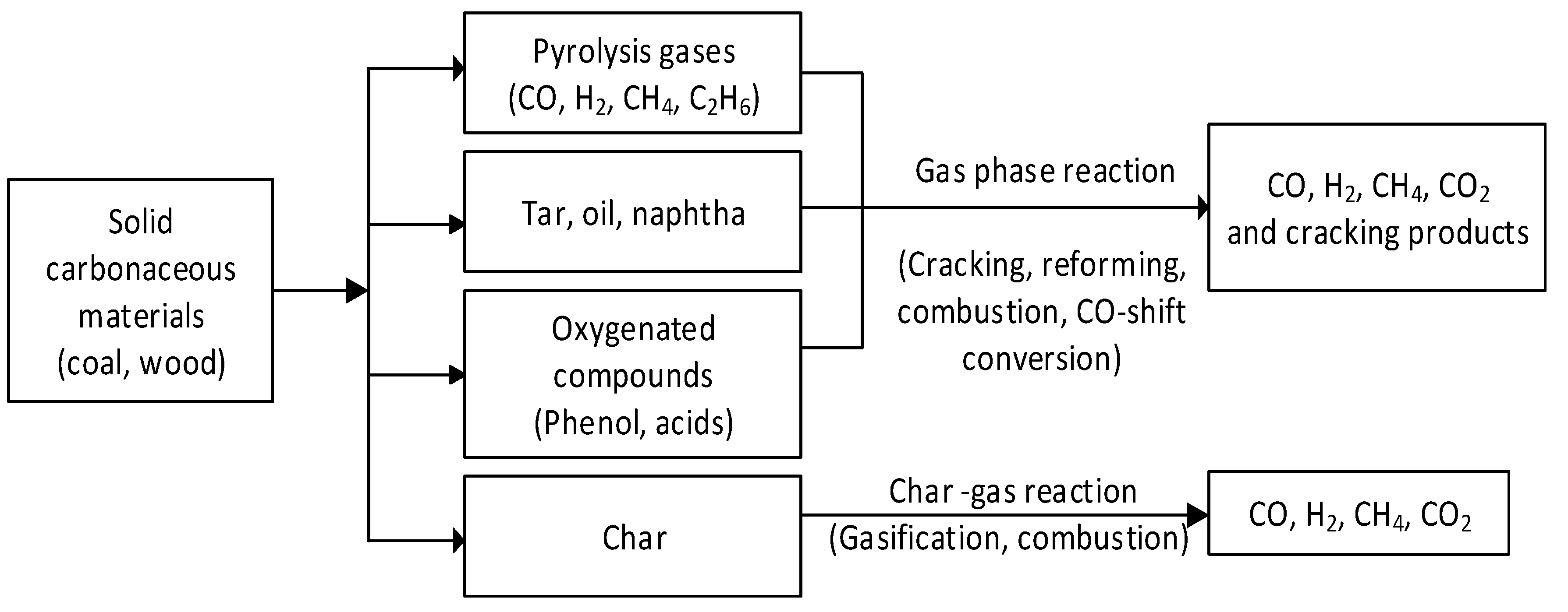
Figure 3.
Reactivity indices for different coal and char samples: (a) effect of H2O/CO2 ratio at a temperature of 1000 °C and a heating rate of 20 °C/min [66]; (b) effect of temperature using a heating rate of 50 °C/min [67].

| Operating Conditions | Fixed Bed | Fluidised Bed | Entrained Flow | |||
|---|---|---|---|---|---|---|
| Ash conditions | Dry ash | Slagging | Dry ash | Agglomerating | Slagging | Slagging |
| Fuel-feeding conditions | Dry feeding | dry feeding | dry feeding | dry feeding | dry feeding | slurry feeding |
| Reactant type | Air/O2 | Air/O2 | Air/O2 | Air/O2 | O2 | O2 |
| Reactant requirement | low | low | medium | medium | high | high |
| Syngas flow direction | up | up | up | up | up or down | up or down |
| Typical reactor temp (°C) | 1000 | 1500–1800 | 900–1050 | 900–1050 | 1200–1600 | 1200–1600 |
| Syngas temperature (°C) | 425–650 | 425–650 | 925–1040 | 925–1040 | 1400–1600 | 1200–1400 |
| Syngas cooling | Water | Water | Coolant | Coolant | Coolant | Water/syngas coolant |
| Pressure (Mpa) | 3.0 | 2.5 | Up to 3.0 | 1.0–3.0 | 2.5–3.0 | 2.5–3.0 |
| Feedstock preference | Low- to high-rank coals and waste | Medium- to high-rank coals, petcoke and waste | Low- to medium rank coals and waste | Low- to medium rank coals, biomass and waste | Low- to high-rank coals, biomass, petcoke and waste | Low- to high-rank coals, biomass, petcoke and waste |
| Typical particle size (mm) | 5–80 | 5–80 | <6 | <6 | <0.1 | <0.1 |
| Residence time (s) | 900–3600 | 900–3600 | 10–100 | 10–100 | 1.5–4 | 1.5 |
| Moisture (%) | No limit | <28 | No limit | No limit | Possible to use coal with high moisture | limited |
| Ash content limit (%) | <15 | <25 | <40 | <40 | 2–25 | <25 |
| Ash fusion temp limit (°C) | Any | Any | >1100 | >1100 | Generally <1300 | Generally <1300 |
| Commercial gasifier | Lurgi | BGL | IDGCC, HTW and KBR | KRW and U-Gas | Shell, PRENFLO, EAGLE, Siemens, MHI | GE, E-Gas |
| Conversion | >99 | >99 | 96 | 95 | 98–99 | 100 |
| Typical cold gas efficiency (%) | ~88 | ~88 | ~85 | 70–80 | ~80 | 74–77 |
| Unit capacity (MWth) | 10–350 | 10–350 | 100–700 | 20–50 | Up to 700 | Up to 700 |
| Key technical issues | Agglomeration and use of hydrocarbon liquid | Agglomeration and use of hydrocarbon liquid | Lower carbon conversion and agglomeration | Lower carbon conversion and agglomeration | Syngas cooling and slagging | Syngas cooling and slagging |
| Parameter | ChevronTexaco | E-Gas | Shell | PRENFLO |
|---|---|---|---|---|
| Fuel type | bituminous coal | bituminous coal | bituminous coal | petroleum coke and bituminous coal |
| Gasification process | single-stage entrained flow | two-stage entrained-flow | single-stage updraft entrained flow | single-stage updraft entrained flow |
| Fuel feeding | slurry feeding | slurry feeding | dry feeding | dry feeding |
| Reactant | 95% pure oxygen | 95% pure oxygen | 95% pure oxygen | 95% pure oxygen |
| Syngas cooler type | downflow radiant, water tube and fire tube | downflow fire tube | downflow water tube | Downflow or upflow radiant water tube and convective water tube |
| Controlling particles | water scrubber | metallic candle filter and water scrubber | candle filter | candle filter |
| Chloride, fluoride and ammonia control | water scrubber | water scrubber | water scrubber | water scrubber |
| Sulphur recovery (%) | 98% | 99% | 99% | 99% |
| Air separation | cryogenic distillation | cryogenic distillation | cryogenic distillation | Cryogenic distillation |
| Combustors | multiple cans | multiple cans | twin vertical silos | twin horizontal silos |
| Firing Temperature, °C | 1287 | 1287 | 1100 | 1260 |
| Heat-recovery steam generator | triple-pressure reheat and natural circulation | triple-pressure reheat and natural circulation | triple-pressure reheat and natural circulation | triple-pressure reheat and natural circulation |
| Slag removal | lock hopper | continuous | lock hoppers | lock hoppers |
Table 3.
Summary of the investigations regarding ash and slag characterisations.
| Ref. | Methods and Materials | Study Parameters | Key Findings |
|---|---|---|---|
| [46] |
| Thermal-expansion behaviour of fly ash of IGCC power plant |
|
| [38] |
| Fusibility and flow properties of laboratory ash |
|
| [47] |
| To characterise the slag and mineral transformation |
|
| [39] |
| Slag viscosity prediction of the ash |
|
| [48] |
| Ash fusion characterisation along with dilatometry and sintering strength tests using the image-based technique |
|
| [49] |
| The effect of the addition of inorganic materials in coal or ash |
|
| [40] |
| Development of a correlation to predict AFT based on the ionic potential of major minerals in the ash |
|
Table 4.
The status of gasification plants and syngas capacity [51].
Table 4.
The status of gasification plants and syngas capacity [51].
| Status | Projects | Gasifiers | Syngas Capacity (GWth) |
|---|---|---|---|
| Operating | 379 | 938 | 173 |
| Development | 131 | 348 | 108 |
| Planned | 146 | 734 | 116 |
| Total | 656 | 2020 | 397 |
Table 5.
Worldwide applications of syngas [51].
Table 5.
Worldwide applications of syngas [51].
| Scheme 2017 | Chemicals (MWth) | Gaseous Fuels (MWth) | Industrial Gases (MWth) | Liquid Fuels (MWth) | Power (MWth) | Total (MWth) |
|---|---|---|---|---|---|---|
| Operating (2017) | 95,000 | 18,000 | 9000 | 42,000 | 11,000 | 175,000 |
| Development (2020) | 50,000 | 27,000 | 6000 | 12,000 | 9000 | 104,000 |
| Planned | 33,000 | 74,000 | 2000 | 6000 | 3000 | 118,000 |
| Total | 178,000 | 119,000 | 17,000 | 60,000 | 23,000 | 397,000 |
| Status | Coal (MWth) | Natural Gas (MWth) | Petcoke (MWth) | Petroleum (MWth) | Biomass (MWth) | Waste (MWth) | Total (MWth) |
|---|---|---|---|---|---|---|---|
| Operating (2017) | 140,000 | 17,000 | 4000 | 13,000 | 1000.0 | 1000 | 175,000 |
| Development (2020) | 84,000 | 0 | 11,000 | 2000 | 0 | 0 | 97,000 |
| Planned (2021) | 110,000 | 2000 | 5000 | 6000 | 2000 | 2000 | 125,000 |
| Total | 334,000 | 19,000 | 20,000 | 21,000 | 3000 | 3000 | 397,000 |
Table 12.
Kinetic parameters for different types of coal using CO2 and steam.
| Char Samples | Ea (kJ/mol) | A0 (s−1) | n (–) | Ref. | |||
|---|---|---|---|---|---|---|---|
| CO2 | Steam | CO2 | Steam | CO2 | Steam | ||
| Barapukurian bituminous coal | 173.4 | 143.4 | 1.21 × 10⁴ | 1.47 × 10³ | 0.67 | 0.95 | [99] |
| Morwell Brown coal | 169.0 | 152.18 | 1.69 × 10⁵ | 8.25 × 10⁴ | 0.39 | 0.55 | [105] |
| Yallourn Brown coal | 168.8 | 152.18 | 2.07 × 10⁵ | 7.14 × 10³ | 0.48 | 0.44 | [105] |
| Loy Yan Brown coal | 164.9 | 119.24 | 3.58 × 10⁴ | 4.59 × 10² | 0.44 | 0.53 | [105] |
| Indonesian sub-bituminous coal | 144.0 | - | 1.74 × 10² | - | 0.4 | - | [108] |
| High-ash Indian sub-bituminous coal | 216.0 | 204 | 3.05 × 10⁶ | 2.88 × 10⁶ | 0.6 | 0.11 | [109] |
| Australian (NL) bituminous coal | 257.0 | - | 2.54 × 10⁷ | - | 0.56 | [110] | |
| Australian (BA) bituminous coal | 283.0 | - | 1.09 × 10⁹ | - | 0.54 | - | [111] |
| Chinese (S) bituminous | 261.0 | 214 | 1.23 × 10⁹ | 2.45 × 10⁴ | 0.49 | 0.86 | [111] |
| Semi-anthracite coal | 282 | - | 7.2 × 10⁸ | - | 0.35 | - | [112] |
| Jingcheng Anthracite coal | 151.5 | 239.8 | 1.53 × 10² | 5.15 × 10⁶ | - | 0.46 | [113] |
Table 13.
Summary of the kinetic models [105].
Table 13.
Summary of the kinetic models [105].
| Models | Separable Form | Linear Form |
|---|---|---|
| Volumetric model (VM) | ||
| Grain model (GM) | ||
| Random Pore Model (RPM) | − 1] |
Publisher’s Note: MDPI stays neutral with regard to jurisdictional claims in published maps and institutional affiliations. |
© 2022 by the authors. Licensee MDPI, Basel, Switzerland. This article is an open access article distributed under the terms and conditions of the Creative Commons Attribution (CC BY) license (https://creativecommons.org/licenses/by/4.0/).
Share and Cite
MDPI and ACS Style
Shahabuddin, M.; Alam, T. Gasification of Solid Fuels (Coal, Biomass and MSW): Overview, Challenges and Mitigation Strategies. Energies 2022, 15, 4444. https://doi.org/10.3390/en15124444
AMA Style
Shahabuddin M, Alam T. Gasification of Solid Fuels (Coal, Biomass and MSW): Overview, Challenges and Mitigation Strategies. Energies. 2022; 15(12):4444. https://doi.org/10.3390/en15124444
Chicago/Turabian StyleShahabuddin, M., and Tanvir Alam. 2022. "Gasification of Solid Fuels (Coal, Biomass and MSW): Overview, Challenges and Mitigation Strategies" Energies 15, no. 12: 4444. https://doi.org/10.3390/en15124444
Note that from the first issue of 2016, this journal uses article numbers instead of page numbers. See further details here.