Article

Recent Studies on the Environmentally Benign Alkaline-Earth Silicide Mg2Si for Middle-Temperature Thermoelectric Applications

1
Department of Materials Science and Technology, Faculty of Advanced Engineering, Tokyo University of Science, 6-3-1 Niijyuku, Katsushika-ku, Tokyo 125-8585, Japan
2
Next Generation TATARA Co-Creation Centre, Shimane University, 1060 Nishi-Kawatsu, Matsue 690-8504, Shimane, Japan
3
Department of Mechanical Systems Engineering, Graduate School of Systems Design, Tokyo Metropolitan University, 6-6 Asahigaoka, Hino, Tokyo 191-0065, Japan
4
Department of Modern Mechanical Engineering, Graduate School of Creative Science and Engineering, Waseda University, 3-4-1 Okubo Shinjuku, Tokyo 169-8555, Japan
*
Author to whom correspondence should be addressed.
Energies 2022, 15(13), 4859; https://doi.org/10.3390/en15134859
Submission received: 9 March 2022 / Revised: 8 June 2022 / Accepted: 20 June 2022 / Published: 2 July 2022
(This article belongs to the Special Issue Advanced Thermoelectric Generation Technologies 2022)

Abstract

:
Most primary energy sources, such as the fossil fuels of oil, coal, and natural gas, produce waste heat. Recycling of this unused thermal energy is necessary in order to increase the efficiency of usage. Thermoelectric (TE) conversion technologies, by which waste heat is directly converted into electricity, have been extensively studied, and the development of these technologies has continued. TE power-generation has attracted significant attention for use in self-powered wireless sensors, which are important for our increasingly sophisticated information society. For the middle-temperature range (i.e., 600–900 K), with applications such as automobiles, intensive studies of high-performance TE materials have been conducted. In this study, we review our recent experimental and theoretical studies on alkaline-earth silicide Mg2Si TE materials, which consist of nontoxic abundant earth elements. We demonstrate improvements in TE performance brought about by lightly doping Mg2Si with isoelectronic impurities. Furthermore, we examine the electrode formation and material coatings. Finally, we simulate the exhaust heat requirements for the practical application of TE generators.

1. Introduction

The realization of an energy-efficient sustainable society is one of the major goals of modern material science. As the world’s energy demand increases with the rapid growth in population and industrial development, efficient and environmentally friendly power generation has received significant attention. Most primary energy sources, such as fossil and atomic fuels, produce waste heat. Thus, there is a need to efficiently recycle this waste heat to produce electrical energy using technology similar to that used to generate electricity from solar radiation, heat from geothermal sources, or even heat from the human body. Thermoelectric (TE) conversion technology has been intensively investigated to convert waste heat directly into electricity without the need for a mechanical drive [1,2].
The efficiency of TE power-generation, η, is classically expressed by the Carnot efficiency, ΔT/Thot, and the dimensionless figure of merit, ZTavg, which is as follows: η = (ΔT/Thot)[{(1 + ZTavg)1/2–1}/{(1 + ZTavg)1/2 + Tcold/Thot}], where Thot and Tcold are the absolute temperatures (K) of the hot and cold sides of a TE material, respectively; ΔT is the difference between them; Tavg is the average temperature between Thot and Tcold, which is denoted as T in this paper. As stated above, the performance of TE materials is determined by ZT = S2σT/(κel + κl), where S is the Seebeck coefficient (V·K−1); σ is the electrical conductivity (S·m−1); κel and κl are the electronic and lattice thermal conductivities (W·m−1·K−1), respectively. The parameters S, σ, and κel depend on the electronic structure of the material, and κl is dominated by the lattice structure. To improve ZT, the power factor (PF = S2σ) (W·m−1·K−2) must be improved by optimizing the carrier concentration and lowering the values of κel and κl. Furthermore, a high mechanical strength and thermodynamic durability over a long period of time under the actual operating temperature and ambient are required to establish reliable TE generators. Additionally, it is necessary to consider the optimal module device structure for each heat source to evaluate the performance of the TE material.
For practical applications, TE technology has been used in radioisotope batteries as a power source for spacecraft [3]. For this approach, SiGe materials have been applied at high temperatures above 900 K. Meanwhile, for medium- and low-temperature applications at temperatures below 900 K, Bi–Te- and Pb–Te-based materials provide high-performance TE materials with ZT > 1, and these have been widely used for more than half a century [4,5]. In particular, Bi–Te-based materials are currently the most widely used TE materials for Peltier cooling devices. However, they contain toxic and rare earth elements, and alternative abundant environmentally friendly materials with high TE performance have been intensively investigated. Figure 1 shows an example of TE materials and their applications depending on the applied temperature.
Mg3Sb2-based Zintl compounds and MgAgSb with high TE performance, which are less toxic than Te and Pb, have recently been studied [6,7,8]. Furthermore, Cu-based and chalcogenide-based TE materials are attracting attention as low-toxicity alternatives [9,10,11]. These have a high TE performance comparable to Pb–Te- and Bi–Te-based materials. However, there is a need for completely environmentally friendly TE materials that do not contain any toxic elements in their base compositions. For example, some silicides and oxide materials meet these requirements [12,13]. The TE performances of environmentally friendly Fe–Al–Si TE alloy materials have also been recently investigated through composition optimization and carrier tuning [14,15]. To further improve the performance of such environmentally friendly TE materials and determine which ones are the best new candidates for TE applications with a lower environmental impact, it is necessary to investigate the possible ways in which the TE performance can be improved using both experimental and theoretical approaches.
In this paper, we review the results of our recent research on the alkaline silicide TE material magnesium silicide (Mg2Si), which is completely environmentally benign. We describe the improvement made in the TE performance of Mg2Si by lightly doping it with isoelectronic impurities. Furthermore, we present studies of the electrode materials, investigations of the material coatings used to improve the durability at high temperature in air, and a thermal simulation of exhaust systems for practical automotive applications. The remainder of this paper is organized as follows. Section 2 describes the effects on the TE properties of lightly doping Mg2Si with isoelectronic impurities. Section 2.1 presents the TE properties of molten Mg2Si doped with Zn and Sb. Section 2.2 gives details of the electrode formation and the electrical resistivity of the contacts. Finally, in Section 3, we present the practical applications of Mg2Si. The thermal simulations of an automobile exhaust system were described.

2. Improvements in the TE Performance of Mg2Si by Lightly Doping It with Isoelectronic Impurities

As a nontoxic, inexpensive, and element-rich material in the Earth’s crust, Mg2Si is a promising candidate for medium-temperature (600–900 K) TE applications, such as surplus heat from industrial thermal plants and internal combustion engines. Furthermore, Mg2Si is lightweight with a density of 1.99 g·cm−3. It is necessary to improve the TE performance of Mg2Si for practical use as a TE conversion material. Thus, several theoretical and experimental studies have been reported [16,17,18,19,20,21,22,23,24,25,26,27,28,29]. In addition to Bi, which is one of the most important dopants in this system [30,31,32], previous studies have shown that Sb is also an efficient n-type dopant for improving ZT because doping Mg2Si with Sb increases σ and decreases κl [33,34,35]. However, there is a practical limit to the doping amount of Sb because the carrier doping increases the output current density of the TE modules, and an excessive current density input increases the direct current power conversion loss. Therefore, only the thermal conductivity must be independently decreased whilst maintaining σ without increasing the carrier density n. Several researchers have reduced κl by nanostructuring and alloying processes, which solve this problem and improve the performance [2,36,37]. However, with nanostructuring, there are difficulties encountered in the preparation of nanoparticles as raw materials and their sintering conditions. This approach is also reported as not effective for Mg2Si, due to the small difference in the phonon and electron mean free paths in this material [38,39]. Furthermore, alloying encounters problems such as the solid solution limit, potential reactions, and the possibility of precipitation of different phases. Alloys of Ge and Sn have been investigated as a system in which Ge and Sn are completely dissolved in Si of Mg2Si [40,41,42]. However, alloying, especially for Mg2SnxSi1−x, degrades the TE performance at temperatures above 700 K due to oxidation [43] as Mg is extremely reactive with oxygen at higher temperatures. Therefore, it is necessary to introduce a suitable approach to reduce κl without using these problematic approaches. We focused on lightly doping Mg2Si with the isoelectronic impurity Zn to reduce κl, hopefully without significantly affecting the electrical properties. As a material background, Section 2.1 outlines the results of our previous studies [44].

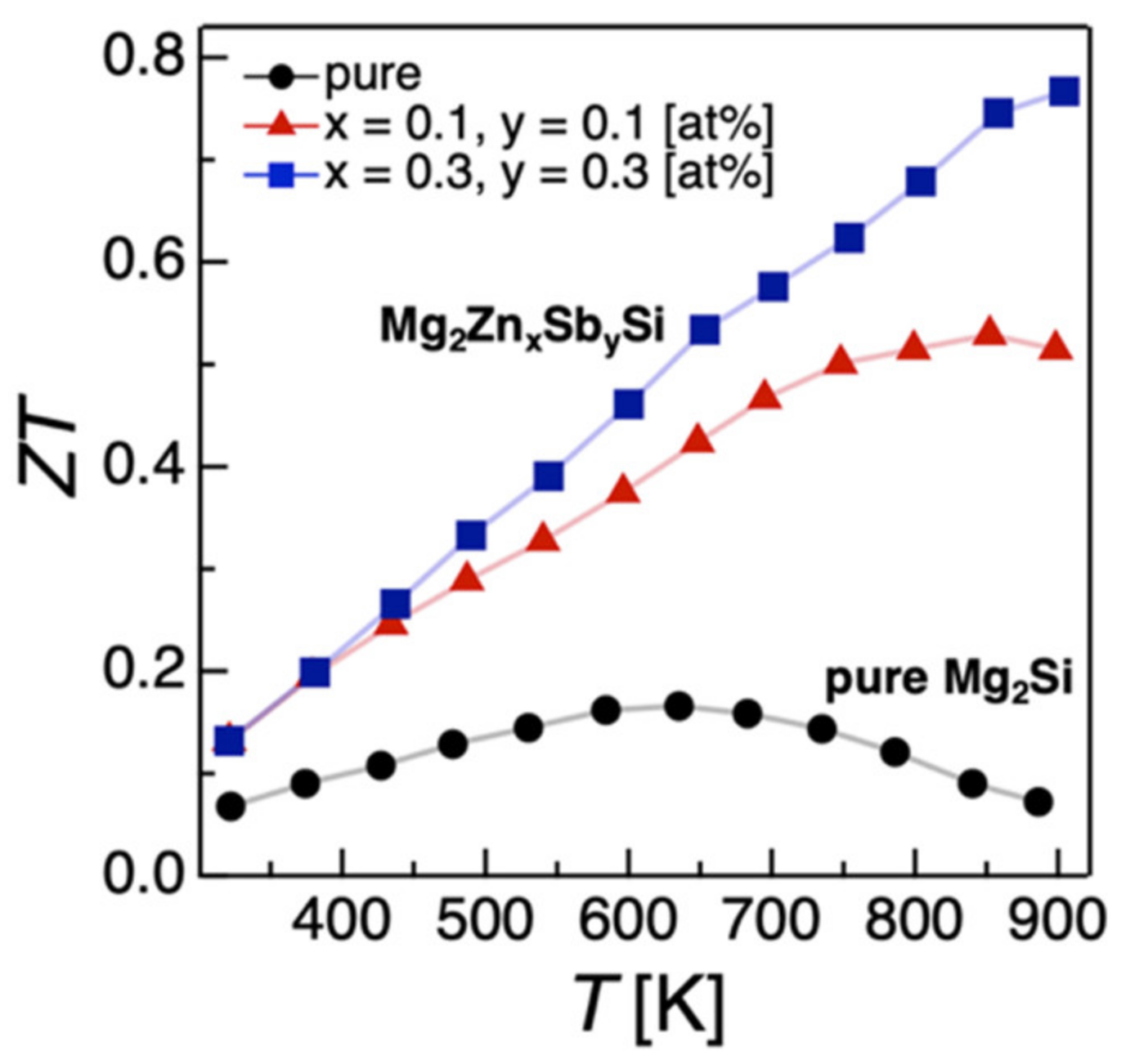
2.1. TE Performance of Mg2Si Codoped with Sb and the Isoelectronic Impurity Zn

2.1.1. Energetic Stabilities

Crystal sites into which impurity elements have been substituted play a significant role in the physical properties of the material. Extended X-ray absorption fine structure analysis has revealed that Sb mainly substitutes into Si sites, and that the proximity distance of Sb atoms becomes expanded [45]. However, no clear data exist for Zn substitution and we do not yet know which crystal sites are favorable. To address this point, we investigated the crystal sites that are most receptive for the isoelectronic impurity Zn. Before presenting the experimental results, we briefly summarize the results of calculations based on conventional density functional theory (DFT).
Mg2Si has an antifluorite crystal structure with the Fm 3 m space group. As shown in Figure 2, we assumed interlattice insertion into the cell at three impurity sites, namely the substituted Mg- and Si-sites and the 4b-site. Mg2Si has been reported to exhibit n-type conduction at stoichiometric compositions due to the partial interlattice substitution of Mg into the 4b-site [46,47].
A 2 × 2 × 2 supercell consisting of eight unit cells was used to investigate impurity-doped systems with a doping concentration x close to the experimental values. When an atom of Mg or Si in the 2 × 2 × 2 supercell is replaced by one impurity atom with simple cubic periodicity, the value of x = 1.042 at%. We performed variable cell relaxation calculations using the Broyden–Fletcher–Goldfarb–Shanno quasi-Newtonian algorithm for estimating stable structures. Other detailed calculation conditions and methods are described in previous studies [44].
The most energetically stable structure of Zn-doped Mg2Si is when the Zn atoms are replaced by Mg atoms, but the energy stability for the 4b-site filled with Zn atoms is equally stable, indicating that both crystal sites are susceptible to doping [44]. The values of lattice constants for Mg63ZnSi32 (Mg-site) and Mg64ZnSi32 (4b-site) change by −1.06% and −0.85%, respectively, relative to pure Mg64Si32. Furthermore, in the energetically stable Mg64SbSi31, the value of the lattice constant is 0.19% larger than in pure Mg64Si32; the ionic radius of Zn is 1–5% larger than that of Mg [48], while the value of the lattice constant in Mg2ZnxSi (x = 1.042 at%) is probably reduced by two mechanisms: (1) The high covalent bonding strength between Zn and Mg restricts the formation of Mg and Zn composites to line compounds based on the phase diagram [49]. (2) Zn doping to the 4b-site may be related to the electronegativity value of 1.65 for Zn and 1.31 for Mg [50]; interstitial insertion of a highly electronegative atom at the 4b-site may decrease the lattice constant, as previously suggested by Imai et al. [51].

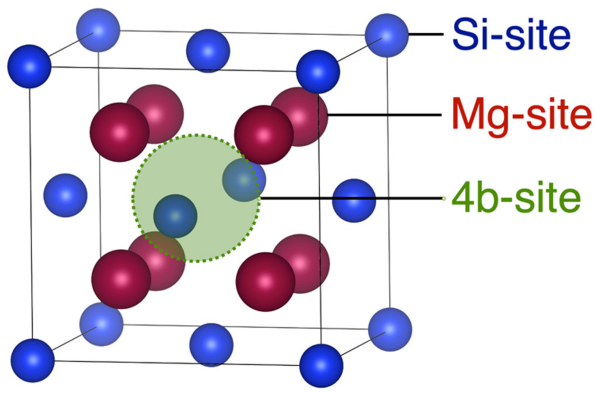
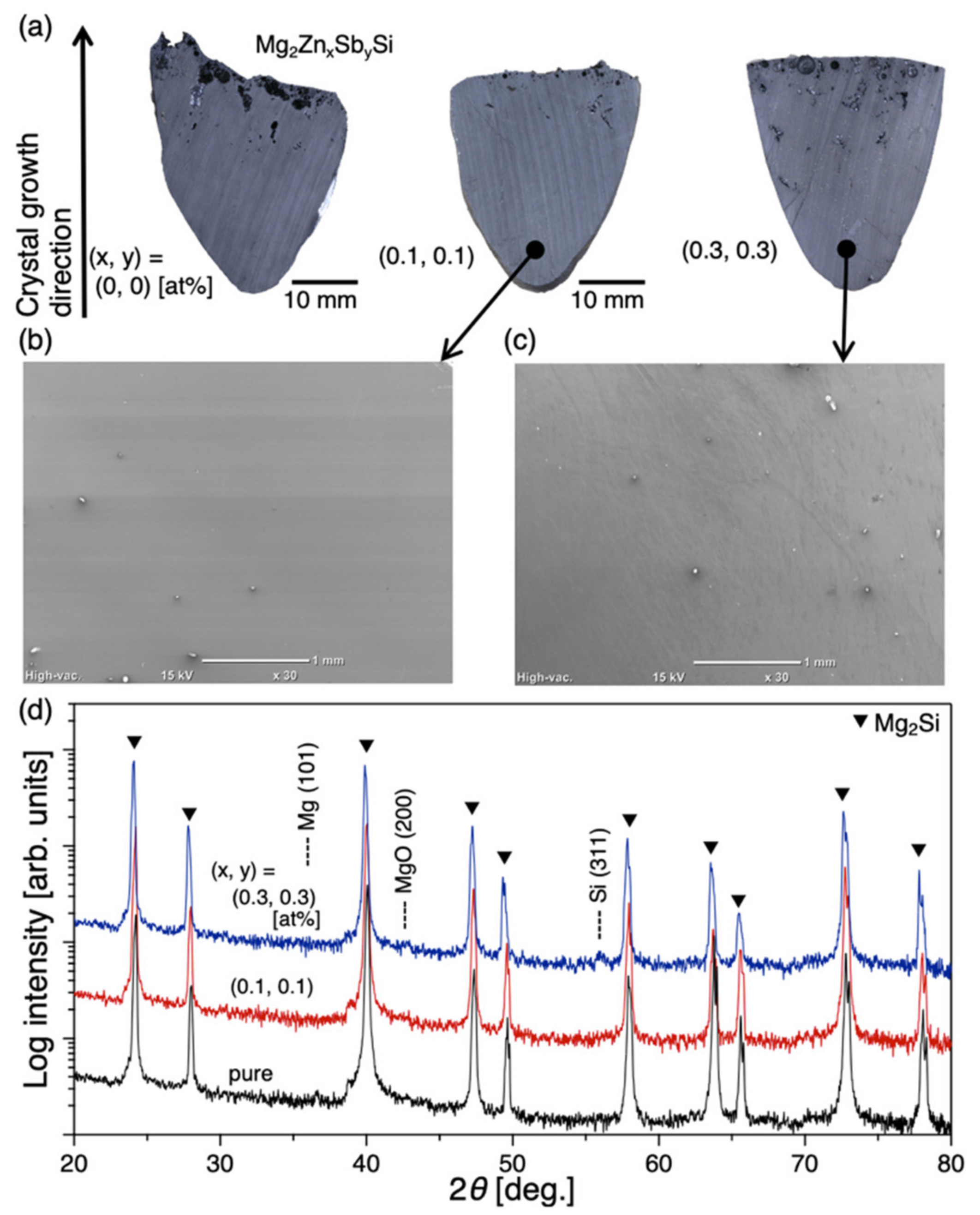
2.1.2. Crystal Structure

Mg2Si doped with Sb and isoelectric impurity Zn was synthesized by the VB method. Figure 3a shows cross-sectional images of VB-grown pure Mg2Si and Mg2Si codoped with Zn and Sb. Dense polycrystalline samples were formed in the bottom regions to avoid the presence of voids in the crystal growth direction. The above observation is also evident from the secondary electron microscope images shown in Figure 3b,c, which show a dense microstructure. It should be noted that Mg and Si are also uniformly distributed in the microstructure, as seen from the energy-dispersive X-ray spectroscopy results, although this is not shown in this report. The bottom regions of the Mg2Si ingots were directly machined to enable measurements of their transport properties to be made. Figure 3d shows the powder XRD patterns of VB-grown Mg2Si doped with Zn and Sb and that of pure Mg2Si. The XRD patterns are mainly consistent with the diffraction pattern of Mg2Si (ICDD card no. 35-0773), indicating that high-purity Mg2MSi (M = Sb and Zn) specimens were fabricated through the VB process in the inert Ar ambient. The lattice constant increases linearly as the Zn and Sb contents increase until it reaches 6.3734 Å at x = y = 0.3 at% compared to 6.3548 Å for pure Mg2Si, indicating that Sb substitution at Si-sites is energetically favorable. Comparisons of changes in lattice constants with calculated values have been described in the literature [44].

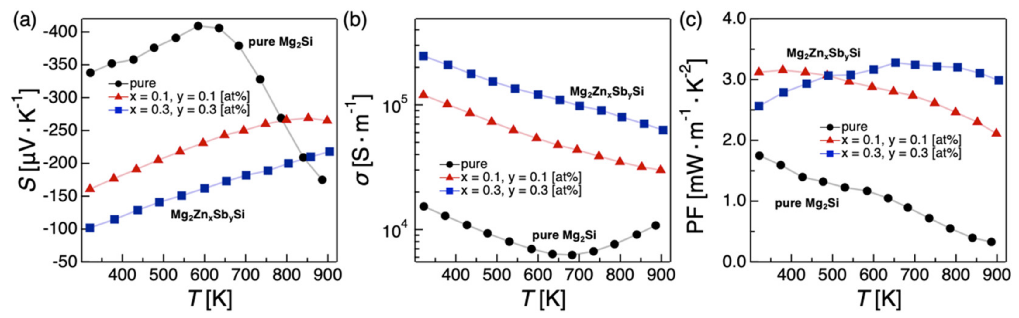
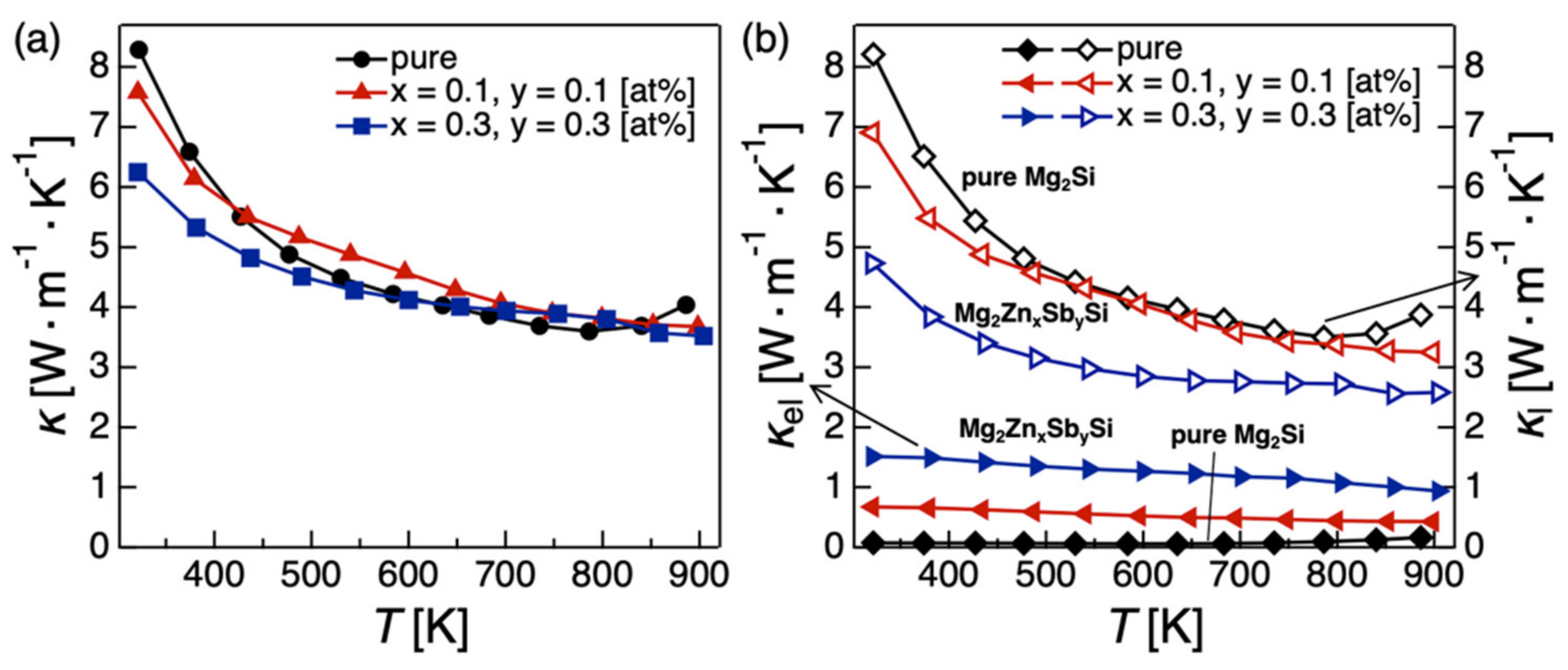
2.1.3. Codoping Effects on the Electronic, Thermal, and TE Properties

Figure 4 shows the values of S, σ, and PF for pure Mg2Si and VB-grown Mg2Si doped with Zn and Sb. The values of σ, S, and PF of VB-grown pure Mg2Si are almost the same as previous results [52]. The value of S of the doped specimens increases monotonically with temperature. The value of S of Mg2MSi (M = Sb, Zn) decreases with increasing doping concentration. The value of σ of the doped specimens increases with Sb and Zn doping concentrations, suggesting that n-type carriers are introduced by Sb doping, and the increase in n owing to impurity atoms outweighs the decrease in electron mobility. It is also possible that the insertion of Zn at 4b sites is not electrically neutral and increases n. The power factor of VB-grown Mg2MSi (M = Sb, Zn) is larger than that of pure Mg2Si in the measured temperature range and increases with the doping concentration above 773 K, a practical application temperature for Mg2Si. For Zn and Sb doping concentrations of 0.3 at%, the VB-grown sample achieves a higher PF at >~500 K.
Figure 5a,b show the total thermal, electronic, and lattice conductivities, κ, κel, and κl, respectively, for the VB-grown pure and Sb- and Zn-doped Mg2Si. We estimated the values of κel from the Wiedemann–Franz law κel ·σ−1= LT, where L is the Lorenz number and T is the absolute temperature. However, L can be taken as 2.44 × 10⁻⁸ W·Ω·K−2, and a more accurate temperature-dependent equation can be used when S is measured: L = 1.5 + exp S / 116 (where L is of the order of 10−8 W·Ω·K−2 and S is in μV·K−1). We determined κel using this equation, which was recently reported [53]. Plots of the lattice thermal conductivity, calculated as κl = κκel, are also presented. The κ value of each specimen decreases rapidly below 423 K, becoming linear at high temperatures. Furthermore, κel increases with the Zn and Sb doping concentrations, reflecting the behavior of σ (Figure 5b). κl decreases with increasing Zn and Sb doping concentrations, showing that the κ values of each sample are not significantly different.
Figure 6 shows that the ZT values are higher in the doped specimens than in Mg2Si over the entire measured temperature range of 323–873 K. The highest ZT among the VB-grown specimens of 0.77 was obtained with Mg2Si codoped with 0.3 at% Zn and Sb at 873 K. These results show that the TE properties of this material can be improved by doping with the isoelectronic impurity Zn.

2.2. Electrodes

In a thermoelectric power generation module (TEM) of relatively medium scale or somewhat larger than those used in energy-harvesting applications, a large current (>~10 A) is usually generated, so the selection of the electrode material and reduction in the contact resistance are important issues for TEM device fabrication. The expected operating temperature range for Mg2Si is 600 to 900 K; thus, thermally durable electrode materials possessing low contact resistance to the Mg2Si matrix up to the maximum process temperature of about 1100 K are needed. Predominantly, Ni electrodes are used, as these have the following attributes: ohmic contact, low contact resistance, processing simplicity, and resource reserve, in addition to stability in the operating temperature range. One possible method of forming an electrode on Mg2Si is by the so-called “monobloc” sintering method, which is a simultaneous sintering process by means of plasma-assisted sintering, which forms an electrode during sintering of the Mg2Si matrix.
In addition, as an electrode forming method suitable for an industrial process, a paste printing method to form an electrode was introduced. In this method, as the sintered body and the electrode formation are performed separately, it is expected that it will be possible to prepare large-diameter samples with an electrode and a uniform element, and the degree of freedom allowed for the structure of the module can be improved due to the electrode patterning. Moreover, as the surface can be processed under dry conditions, there is an advantage that there is no corrosion, as seen in the plating method for group-II alkaline-earth silicides.
As a promising electrode metal, Ni was deposited on n-type Mg2Si doped with antimony (donor impurity at Si site) and zinc (isoelectric impurity at Mg site) [54] by means of monoblock sintering and the paste printing method. The monobloc sintering process was performed at 1143 K and 50 MPa for 15 min in an Ar atmosphere. In the paste printing method, a paste with 400 nm Ni particles was printed onto a Mg2Si-sintered pellet (30 mm in diameter), followed by a drying process (553 K: 60 min, under Ar atmosphere) and a firing process (973 K: 30 min, Ar atmosphere). The obtained Ni electrode layer thicknesses were 300 μm (monobloc sintering method) and 80 mm (paste printing method), respectively.
Table 1 shows the contact resistance results for the Ni-electrode/Mg2Si interface and the power generation characteristics with a temperature difference of 373/873 K for thermoelectric power generation elements of 3 mm × 3 mm × 7.6 mm in size. The contact resistance was measured using a resistance distribution measuring device at room temperature. With the electrode formed by the monobloc sintering method, low-contact-resistance characteristics were obtained at the Ni-electrode/Mg2Si interface with a sufficiently low contact resistivity of <1 × 10⁻⁹ Ωm2, which is a good practical value. On the other hand, with the paste printing electrode, the contact resistivity was 1.52 × 10⁻⁹ Ωm2.
SEM-EDX measurements at the Ni-electrode/Mg2Si interface showed no critical inter diffusion of the constituent elements of Ni and Mg2Si during the formation process, while intermediate layers, denoted as the η-phase and the ω-phase, at the Ni-electrode/Mg2Si interface were observed for both Ni-electrodes fabricated by the monobloc sintering method, as shown in Figure 7a. To understand these two intermediate layers, high-resolution cross-sectional transmission electron microscope (HR-XTEM) observations were performed using a JEOL JEM-4010 at 400 keV. Figure 7b shows the measured XTEM image for the Ni-electrode/Mg2Si interface of the TE chip. From analyses of the diffraction patterns from selected areas of the Ni/Mg2Si interface, the compositions of the η- and ω-phases were revealed to be the intermetallic compounds Mg6Si7Ni16 (Pearson symbol: cF116, Prototype: Mn23Th6) and Mg33Si37Ni30 (hP55, Ag7Te4), respectively. Additionally, another phase of MgNi2 (hP24) was discovered between the Ni electrode and the η-phase. These intermediate layers were formed during the monobloc sintering process and were found to be stable. The mutual diffusion of Ni, Mg, and Si at the interface in an elevated temperature state is considered to show a difference in the diffusion coefficient of the mutually diffused atoms and, therefore, intermediate layers can be formed (Kirkendall effect). With a Ni-electrode/Mg2Si interface that has a boundary layer induced by the Kirkendall effect, there is a concern that the thermal durability of the intermediate layer will decrease. A thorough investigation of this issue is required. However, subsequent aging tests on several specimens at 873 K in air for 1000 h indicated no notable broadening due to Ni diffusion.
The Ni electrode formed using the paste printing method and subsequent calcination process showed an electrode peeling rate of 0%. At the Ni-electrode/Mg2Si interface, the Ni-Si diffusion layer, seen in the monobloc sintering method, could not be confirmed, and the SEM-EDX measurements revealed no notable inter-diffusion at the Ni-electrode/Mg2Si interface. However, the contact resistivity between the electrode and the base metal was ~1.5 × 10⁻⁹ Ωm2, which is slightly higher than 1.0 × 10⁻⁹ Ωm2, which is the upper value for practical use. Subsequently, a high-temperature durability test in air was conducted for up to 5000 h at 873 K, a temperature considered as the assumed operating temperature of the Mg2Si TEM device. Figure 8 shows the results of optical micrograph observations on the Ni-electrode/Mg2Si interface for (a) the as-sintered specimen and (b) the thermally aged specimen. As shown in Figure 8, it is confirmed that the η- and the ω-phases are formed in a two-layer structure along the boundary between the Ni-electrode and the Mg2Si matrix. From the results for the aged Ni-electrode/Mg2Si interface, it is seen that no clear trace of precipitation such as MgO and Ni-Si was observed. As the Ni-electrode/Mg2Si junction was formed during the monobloc sintering process at 1143 K, it is probable that no notable deterioration was observed in the thermal durability test at 873 K, due to an endurance condition at a thermally low temperature. As this sintering process was performed in a very short time (15 min), it is probable that the amount of mutual diffusion at the interface was limited; thus, influences on intermediate-layer formation due to the Kirkendall effect were not clearly observable in our results. Subsequently, a high-temperature durability test in air was conducted for up to 5000 h at 873 K. No precipitates such as MgO and Ni-Si were observed at the junction interface. In addition, no significant change in contact resistivity was observed with the passage of time. Considering that the sintered body used contains Sb, it was clarified that it is possible to fabricate practical TEMs consisting of Sb + Zn-doped Mg2Si using this method. The thermal stability of ternary compounds that may appear at the Mg2Si-Ni interface was evaluated by density functional theory. According to the results, the η-phase and MgNi2 phase are stable, while the ω-phase was predicted to be less stable. Further investigation of the detailed structure of this phase would be necessary [55].

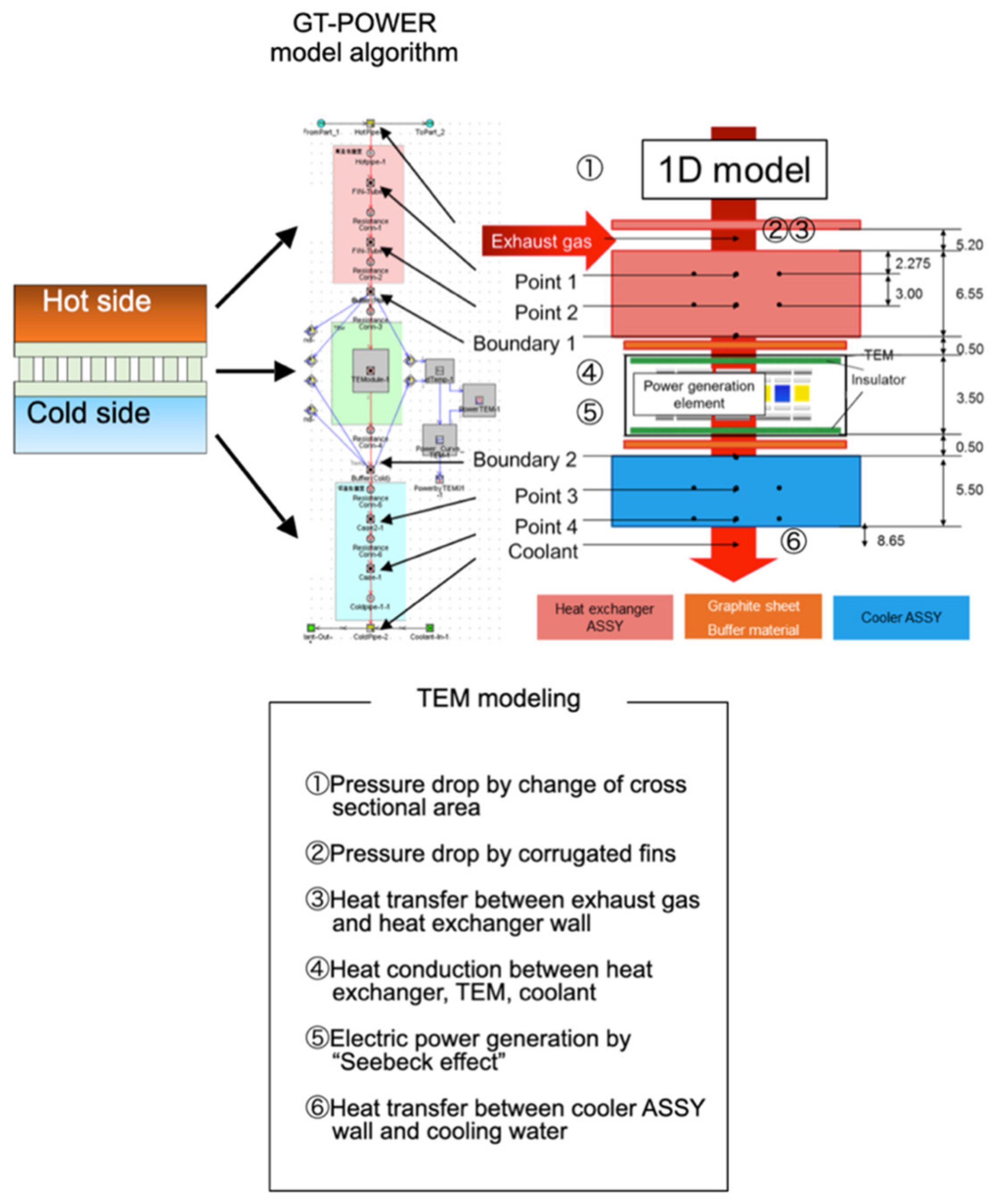
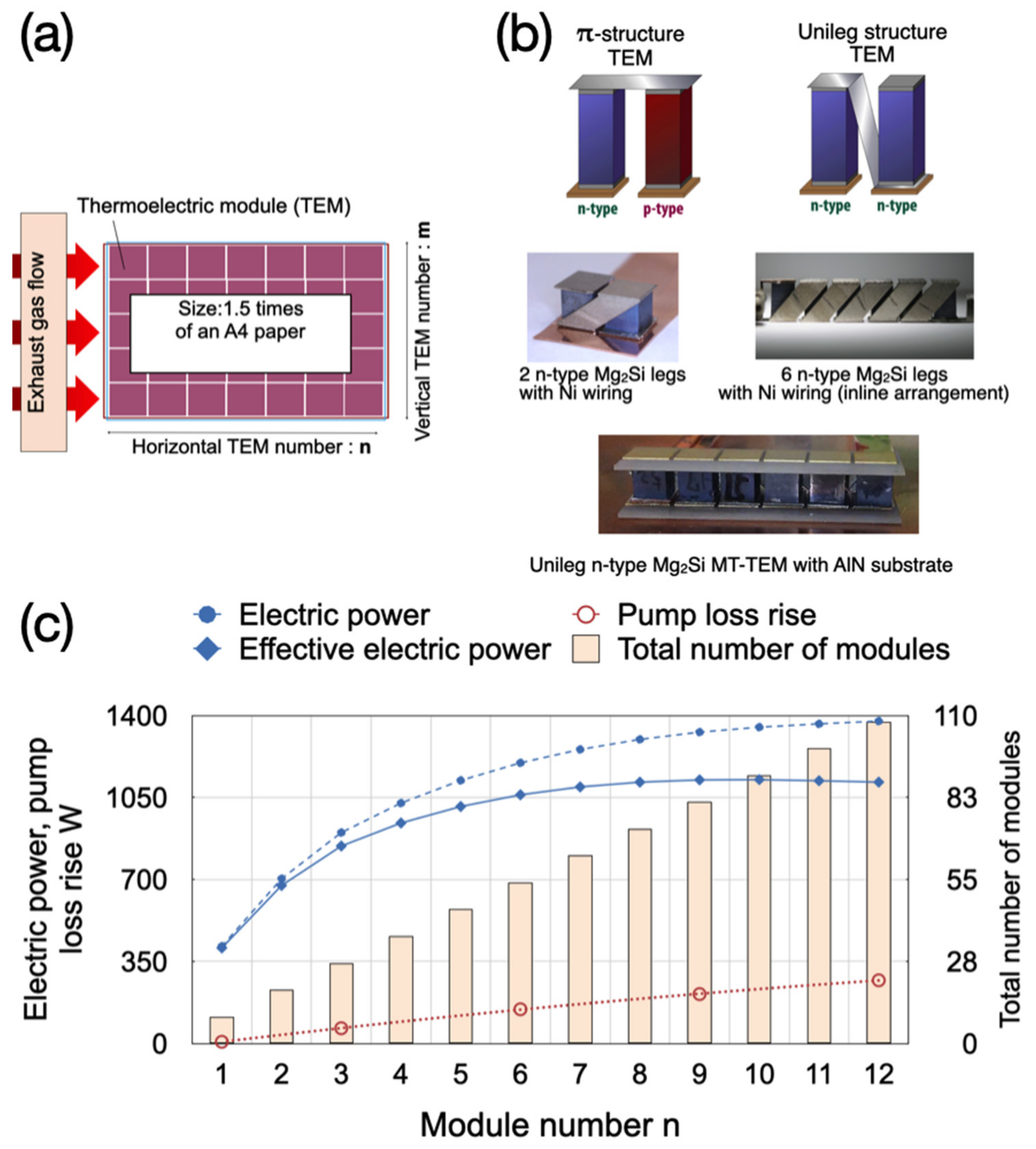
3. Thermoelectric Generator Modeling in Combustion Engine Simulator

Conventionally, the exhaust heat from a range-extender engine mounted on an electric vehicle (EV) or plug-in hybrid vehicle (PHEV) is simply discharged to the atmosphere. This unused exhaust heat can be converted to regenerate power by thermal-to-electric direct power generation using thermoelectric conversion technology. Supplementing the in-vehicle power generation, which is in tight demand, we constructed a waste-heat power generation unit using the engine exhaust that can contribute to improving the fuel efficiency (CO2 reduction) by 2 to 3% or more in vehicles equipped with electric motors. In electric vehicles such as EVs and PHEVs, the engine operates only as a generator, so it is expected that the system design for improving the operation (engine rotation speed, load, etc.) of the thermal power generation system can be facilitated. As a method of recovering the exhaust energy using a waste heat power generation unit, a system for recovering the exhaust heat after the turbocharger is assumed.
For calculating the contribution to the system thermal efficiency by introducing a specific waste heat power generation unit, “GT-POWER”, a common car system simulation software developed by Gamma Technologies, was used to calculate the contribution the waste heat power generation unit makes to the engine on a thermal efficiency basis. Using the GT-POWER software, we designed a car system on a computer and implemented this on a platform that can perform fuel efficiency measurements, engine evaluation, cooling system evaluation, etc., under arbitrary driving conditions. The engine model in GT-POWER is shown in Figure 9a. By combining objects such as the intake system piping, cylinders, and turbocharger (turbine + compressor) on the interface, it is possible to build a simulation of the total engine system in GT-POWER and obtain the target output and boost pressure. Each constituent object operates in conjunction with each other, and repeated coupled calculations are performed. Figure 9b presents a schematic configuration of the waste heat power generation unit in a combustion engine exhaust line.
In the precise calculation of the contribution to the engine efficiency of the waste heat power generation unit, it is necessary to precisely simulate the heat exchange installed in the exhaust gas flow path, the heat exchange section, and the heat dissipation in the cooling system heat exchanger section. A new one-dimensional model of a waste heat power generation unit was constructed. Figure 10 shows an outline for creating a one-dimensional model of the waste heat power generation unit in GT-POWER. GT-POWER possesses an algorithm that calculates from the heat exchanger of the exhaust gas part to the heat dissipation of the cooling system as a one-dimensional heat transfer problem, and various heat transfer elements existing in the path from the exhaust gas pipe to the cooling water were manufactured to meet the object requirements of GT-POWER. The model was also calibrated using the experimental values in the verification test.
In a typical combustion engine, the temperature of the exhaust gas decreases from the upstream part closer to the engine to the downstream part, by an amount in the range of about 373 to 973 K depending on the engine load, so it is necessary to select a TEM that operates in this temperature range and has durability. A single type of TEM that can cover the whole temperature range is still under development. For this reason, a tandem TEM arrangement in the waste heat power generation unit, which is composed of two TEMs working in the medium-temperature range from 573 to 973 K (MT-TEM) and the low-temperature range from 373 to 523 K (LT-TEM), was arranged in series in the gas flow direction as a practical solution. A Mg2Si element consisting of a unileg (n-type) structure (0.79 W/cm2 at 800 K) developed by the Tokyo University of Science as a MT-TEM, and a BiTe element whose characteristics were tuned for in-vehicle use (0.73 W/cm2 at 450 K) as an LT-TEM were installed in the developed waste heat power generation unit model.
The data required to build the GT-POWER waste heat power generation model were obtained from a verification test using a blower device that simulates the engine exhaust gas characteristics. Figure 11 shows a schematic setup diagram of the thermoelectric power generation system verification test equipment (exhaust gas diffuser, heat exchanger, thermoelectric module, and cooling unit) for which the verification test was conducted.
Using the prepared waste heat power generation unit in GT-POWER, we connected it to the latest gasoline engine model with a thermal efficiency of ~50% (engine displacement of 2.2 L, rotation speed of 2000 rpm, air excess rate of λ = 2.0, and turbocharger installed) and performed thermal efficiency simulation calculations. The layout of one layer of the waste heat power generation unit and the basic structure of the unileg Mg2Si MT-TEM used are shown in Figure 12a,b, respectively. The TEMs located in the power generation model were arranged in a tandem structure in GT-POWER, with Mg2Si MT-TEMs in the first two rows (horizontal TEM numbers 1 and 2) and BiTe LT-TEMs in the third and remaining rows. The waste heat power generation unit is composed of three layers, as illustrated in Figure 12b.
A typical Mg2Si MT-TEM module has a Π-shaped structure consisting of p-type and n-type materials. On the other hand, our Mg2Si MT-TEM module is composed of a unique structure consisting only of n-type material to make the best use of the high performance of the n-type Mg2Si material. Wiring to connect TE chips using Ni metal material was placed in the part connecting between Mg2Si TE chips as an alternative to p-type materials in Π-shaped structural modules. As Ni metal wiring has a higher thermal conductivity than p-type materials, heat loss due to heat flow flowing through the Ni metal wiring part becomes a problem. This is one of the concerns in the unileg structure.
The unileg modular structure using six n-type TE chips is shown in Figure 12b. In the modular structure design using the current finite element method (FEM) simulation, we found from our experiments that heat flow loss is closely associated with the following factors: (1) the TE characteristics and dimension of the TE chip, (2) the thickness and length of the Ni metal wiring and the distance from the TE chip, and (3) the heat transfer characteristics of the substrate. In an early unileg modular structure, which did not pay much attention to these heat flow loss factors, the unileg structural loss was as high as 67%, but by adjusting the heat flow loss factor, the unileg structural loss was now reduced to 38%. It is assumed following the FEM simulation based on our tentative experimental results that the latest modular structure with the further optimized heat flow loss factor can reduce unileg structural loss to 10% or less. Verification experiments with actual modular structures are underway.
Regarding the production of modules with a unileg structure, in the case of the inline-type structure, as shown in Figure 12b, there is no serious difficulty in the process of sandwiching the TE chip between the Ni metal wiring parts and joining the joint parts. However, the procedure is currently complicated when manufacturing a square modular structure, so it is necessary to consider a better method.
Figure 12c shows the results of the total power generated through the TEMs, the pump loss, and the effective power generated excluding the pump loss from the total power generated with respect to the number of TEM rows in the gas flow direction for a waste heat recovery (WHR) unit. In terms of size, the assumed WHR unit used in this calculation can be installed in the exhaust system of a C-segment automobile in Europe, and the introduction cost at the time of mass production is assumed to be ~USD 500 or less (parts cost and process cost).
The total power generated by the three-layer structure in the entire thermoelectric generation module increases according to the number of module rows. As the amount of heat is sequentially reduced by thermal power generation from the upstream side of the thermal power generation unit, the amount of heat that can be recovered becomes smaller toward the downstream side along the gas flow. Therefore, the amount of power generated by the latter stages in the thermal power generation module decreases, and the total amount of power generated reaches a plateau. On the other hand, when the number of columns of the thermal power generation unit is increased, the pump loss rise increases due to the increase in the pipe friction of the heat exchanger section. Under the conditions used in this model study, a thermal efficiency improvement of 0.97% was obtained, corresponding to an approximately 1.9% improvement in fuel efficiency (vertical/horizontal TEM number; m × n = 8 × 9 arrangement).

4. Summary

In this review, improvements in the TE performance of Mg2Si resulting from the light doping with isoelectronic impurities and the formation of electrodes on Mg2Si were investigated. Furthermore, considering the practical use of thermoelectric materials, the contribution of the proposed TE modules to fuel efficiency was calculated by simulating the exhaust heat environment of an automobile.
First, we investigated the codoping effects of Zn and Sb on its TE properties of Mg2Si. All doping specimens exhibited higher PFs than that of the pure Mg2Si. The κ values of the doping samples were similar to that of pure Mg2Si due to the decrease in κl. As a result, higher TE performances were achieved in codoping Mg2Si. The VB method does not require the pulverization, sintering, or vacuum processes, enabling mass production of high-performance, eco-friendly Mg2Si, making them feasible for practical applications.
Second, monobloc sintering and paste printing were performed to fabricate Ni electrodes on Mg2Si pellets codoped with Sb and Zn. With both methods, electrodes were formed without delamination from Mg2Si, and contact resistivities of about ~10−9 Ωm2 were obtained. The contact resistance was small enough relative to the internal resistance of the TE chip and had little effect on its power generation efficiency. SEM and TEM observations showed various Mg–Si–Ni layers at the interface between the Ni electrode and Mg2Si in the electrode formed using the monobloc sintering method, but these intermetallic compounds did not appear when the paste printing method was used. In addition, these electrodes had sufficient thermodynamic stability at 873 K in air.
Finally, the contribution of the waste-heat power generation unit to the thermal efficiency of an engine was calculated using the GT-POWER software, which was implemented on a platform that allows a user to design a car system on a computer and evaluate its fuel consumption, engine, and cooling system under any driving condition. A new one-dimensional model of the waste-heat generation unit was constructed to accurately calculate the contribution of the unit to the thermal efficiency of the engine. Assuming a recent gasoline engine and a TE module with unileg Mg2Si and BiTe TE elements, the thermal efficiency improvement in the present model was 0.97%, which corresponds to a fuel efficiency enhancement of about 1.9%.

Author Contributions

Methodology, validation, formal analysis, and investigation for entire study, T.I. and D.S.; methodology, analysis, and investigation of material calculations and evaluations, N.H. and Y.I.; methodology, analysis, and investigation of electrodes, T.I. and H.S.; methodology, analysis, and investigation of modeling in combustion engine simulator, T.I. and J.K.; writing (original draft preparation), T.I. and D.S.; review and editing, and visualization, D.S. and T.I.; supervision, D.S. and T.I.; funding acquisition, T.I. and D.S. All authors have read and agreed to the published version of the manuscript.

Funding

This study was partly supported by research grants from the Japan Society for the Promotion of Science KAKENHI (Grant Numbers 19H00772 and 20H02137); Council for Science, Technology, and Innovation; Cross-Ministerial Strategic Innovation Promotion Program; “Innovative Combustion Technology” (funding agency: Japan Science and Technology Agency (JST)); JST-Mirai Program (Grant Number JPMJMI19A1).

Institutional Review Board Statement

Not applicable.

Informed Consent Statement

Not applicable.

Data Availability Statement

Not applicable.

Acknowledgments

The work presented in this paper is supported by Yoji Imai (Tokyo University of Science) and Naomi Hirayama (Shimane University), Keisuke Yokota (Waseda University), Takahide Motegi (Waseda University), Hirofumi Tsuchida (Nissan Motor Co., Ltd.), Yasuhiko Izumi (Honda R&D Co., Ltd.), Kei Yoshimura (Suzuki Co., Ltd.), and Toshihiro Shibata (Sango Co., Ltd.). The authors also thank the Nagoya University Information Technology Center for allowing the use of their facilities.

Conflicts of Interest

The authors declare no conflict of interest.

References

  1. He, J.; Tritt, T.M. Advances in thermoelectric materials research: Looking back and moving forward. Science 2017, 357, 1369. [Google Scholar] [CrossRef] [PubMed] [Green Version]
  2. Sootsman, J.R.; Chung, D.Y.; Kanatzidis, M.G. New and old concepts in thermoelectric materials. Angew. Chem. Int. Ed. Engl. 2009, 48, 8616–8639. [Google Scholar] [CrossRef] [PubMed]
  3. Radio Corporation of America, Astro-Electronics Division; U.S. Atomic Energy Commission. High-Temperature Radioisotope Thermoelectric Generator for Space Applications; Radio Corporation of America, Astro-Electronics Division; U.S. Atomic Energy Commission: Washington, DC, USA, 1964. [Google Scholar]
  4. Goldsmid, H.J. Bismuth Telluride and Its Alloys as Materials for Thermoelectric Generation. Materials 2014, 7, 2577–2592. [Google Scholar] [CrossRef] [PubMed] [Green Version]
  5. Goldsmid, H.J.; Douglas, R.W. The use of semiconductors in thermoelectric refrigeration. Br. J. Appl. Phys. 1954, 5, 386–390. [Google Scholar] [CrossRef]
  6. Liu, Z.; Sato, N.; Gao, W.; Yubuta, K.; Kawamoto, N.; Mitome, M.; Kurashima, K.; Owada, Y.; Nagase, K.; Lee, C.-H.; et al. Demonstration of ultrahigh thermoelectric efficiency of ∼7.3% in Mg3Sb2/MgAgSb module for low-temperature energy harvesting. Joule 2021, 5, 1196–1208. [Google Scholar] [CrossRef]
  7. Zhang, J.; Song, L.; Pedersen, S.H.; Yin, H.; Hung, L.T.; Iversen, B.B. Discovery of high-performance low-cost n-type Mg3Sb2-based thermoelectric materials with multi-valley conduction bands. Nat. Commun. 2017, 8, 13901. [Google Scholar] [CrossRef] [Green Version]
  8. Liu, Z.; Mao, J.; Sui, J.; Ren, Z. High thermoelectric performance of α-MgAgSb for power generation. Energy Environ. Sci. 2018, 11, 23–44. [Google Scholar] [CrossRef]
  9. Wei, T.-R.; Qin, Y.; Deng, T.; Song, Q.; Jiang, B.; Liu, R.; Qiu, P.; Shi, X.; Chen, L. Copper chalcogenide thermoelectric materials. Sci. China Mater. 2019, 62, 8–24. [Google Scholar] [CrossRef] [Green Version]
  10. Li, S.; Li, X.; Ren, Z.; Zhang, Q. Recent progress towards high performance of tin chalcogenide thermoelectric materials. J. Mater. Chem. 2018, A6, 2432–2448. [Google Scholar] [CrossRef]
  11. Qiu, P.; Shi, X.; Chen, L. Cu-based thermoelectric materials. Energy Storage Mater. 2016, 3, 85–97. [Google Scholar] [CrossRef]
  12. Ohtaki, M. Recent aspects of oxide thermoelectric materials for power generation from mid-to-high temperature heat source. J. Ceram. Soc. Jpn. 2011, 119, 770–775. [Google Scholar] [CrossRef] [Green Version]
  13. Nozariasbmarz, A.; Agarwal, A.; Coutant, Z.A.; Hall, M.J.; Liu, J.; Liu, R.; Malhotra, A.; Norouzzadeh, P.; Öztürk, M.C.; Ramesh, V.P.; et al. Thermoelectric silicides: A review. Jpn. J. Appl. Phys. 2017, 56, 05DA04. [Google Scholar] [CrossRef]
  14. Hou, Z.; Takagiwa, Y.; Shinohara, Y.; Xu, Y.; Tsuda, K. First-principles study of electronic structures and elasticity of Al2Fe3Si3. J. Phys. Condens. Matter. 2021, 33, 195501. [Google Scholar] [CrossRef]
  15. Takagiwa, Y.; Isoda, Y.; Goto, M.; Shinohara, Y. Conduction type control and power factor enhancement of the thermoelectric material Al2Fe3Si3. J. Phys. Chem. Solids 2018, 118, 95–98. [Google Scholar] [CrossRef]
  16. Hirayama, N.; Imai, Y.; Hamada, N. Conduction band engineering of Mg2Si by isotropic strain for enhancement of thermoelectric performance: A first-principles study. J. Appl. Phys. 2020, 127, 205107. [Google Scholar] [CrossRef]
  17. Hirayama, N.; Iida, T.; Sakamoto, M.; Nishio, K.; Hamada, N. Substitutional and interstitial impurity p-type doping of thermoelectric Mg2Si: A theoretical study. Sci. Technol. Adv. Mater. 2019, 20, 160–172. [Google Scholar] [CrossRef] [Green Version]
  18. Masuoka, Y.; Mito, Y.; Ogino, A.; Nakamura, T.; Amano, K.; Asahi, R. Collaborative effects of Zn and Sb co-doping in magnesium silicide for thermoelectric applications. J. Alloys Compd. 2019, 781, 606–612. [Google Scholar] [CrossRef]
  19. Imai, Y.; Hirayama, N.; Yamamoto, A.; Iida, T.; Takarabe, K. Exploratory Study of Substitutional Elements in Mg2Si for Inducing State of Negative Chemical Pressure. Mater. Trans. 2018, 59, 1417–1422. [Google Scholar] [CrossRef]
  20. Imai, Y.; Mori, Y.; Nakamura, S.; Takarabe, K. Consideration about the synthesis pressure effect on lattice defects of Mg2Si using first-principle calculations. J. Alloys Compd. 2016, 664, 377–569. [Google Scholar] [CrossRef]
  21. Imai, Y.; Sohma, M.; Suemasu, T. Effect of oxygen incorporation in the Mg2Si lattice on its conductivity type—A possible reason of the p-type conductivity of postannealed Mg2Si thin film. J. Alloys Compd. 2016, 676, 91–95. [Google Scholar] [CrossRef]
  22. Kubouchi, M.; Hayashi, K.; Miyazaki, Y. Electronic structure and thermoelectric properties of boron doped Mg2Si. Scr. Mater. 2016, 123, 59–63. [Google Scholar] [CrossRef]
  23. Hirayama, N.; Iida, T.; Funashima, H.; Morioka, S.; Sakamoto, M.; Nishio, K.; Kogo, Y.; Takanashi, K.; Hamada, N. First-principles study on structural and thermoelectric properties of Al- and Sb-doped Mg2Si. J. Electron. Mater. 2015, 44, 1656–1662. [Google Scholar] [CrossRef]
  24. Oto, Y.; Iida, T.; Sakamoto, T.; Miyahara, R.; Natsui, A.; Nishio, K.; Kogo, Y.; Hirayama, N.; Takanashi, Y. Thermoelectric properties and durability at elevated temperatures of impurity doped n-type Mg2Si. Phys. Status Solidi C 2013, 10, 1857–1861. [Google Scholar] [CrossRef]
  25. Imai, Y.; Mori, Y.; Nakamura, S.; Takarabe, K. Energetic consideration of the conduction type of Mg2Si doped with Cu, Ag, or Au using first-principle calculations. J. Alloys Compd. 2013, 549, 175–178. [Google Scholar] [CrossRef]
  26. Meng, Q.S.; Fan, W.H.; Chen, R.X.; Munir, Z.A. Thermoelectric properties of Sc- and Y-doped Mg2Si prepared by field-activated and pressure-assisted reactive sintering. J. Alloys Compd. 2011, 509, 7922–7926. [Google Scholar] [CrossRef]
  27. Sakamoto, T.; Iida, T.; Matsumoto, A.; Honda, Y.; Nemoto, T.; Sato, J.; Nakajima, T.; Taguchi, H.; Takanashi, Y. Thermoelectric characteristics of a commercialized Mg2Si source doped with Al, Bi, Ag, and Cu. J. Electron. Mater. 2010, 39, 1708–1713. [Google Scholar] [CrossRef] [Green Version]
  28. Akasaka, M.; Iida, T.; Matsumoto, A.; Yamanaka, K.; Takanashi, K.; Imai, T.; Hamada, N. The thermoelectric properties of bulk crystalline n- and p-type Mg2Si prepared by the vertical Bridgman method. J. Appl. Phys. 2008, 104, 013703. [Google Scholar] [CrossRef]
  29. Imai, Y.; Watanabe, A.; Mukaida, M. Electronic Structures of Semiconducting Alkaline-Earth Metal Silicides. J. Alloys Compd. 2013, 358, 257. [Google Scholar] [CrossRef]
  30. Fiameni, S.; Battiston, S.; Soldrini, S.; Famengo, A.; Agresti, F.; Barison, S.; Fabrizio, M. Synthesis and characterization of Bi-doped Mg2Si thermoelectric materials. J. Solid State Chem. 2012, 193, 142–146. [Google Scholar] [CrossRef]
  31. You, S.W.; Kim, I.H. Solid-state synthesis and thermoelectric properties of Bi-doped Mg2Si compounds. Curr. Appl. Phys. 2011, 11, S392–S395. [Google Scholar] [CrossRef]
  32. Tani, J.; Kido, H. Thermoelectric Properties of Bi-Doped Mg2Si Semiconductors. Phys. B Condens. Matter 2005, 364, 218–224. [Google Scholar] [CrossRef]
  33. Li, J.; Li, X.; Cai, B.; Chen, C.; Zhang, Q.; Zhao, Z.; Zhang, L.; Yu, F.; Yu, D.; Tian, Y.; et al. Enhanced thermoelectric performance of high pressure synthesized Sb-doped Mg2Si. J. Alloys Compd. 2018, 741, 1148–1152. [Google Scholar] [CrossRef]
  34. Kambe, K.; Udono, H. Convenient melt-growth method for thermoelectric Mg2Si. J. Electron. Mater. 2015, 43, 2212–2217. [Google Scholar] [CrossRef]
  35. Tani, J.I.; Kido, H. Thermoelectric properties of Sb-doped Mg2Si semiconductors. Intermetallics 2007, 15, 1202–1207. [Google Scholar] [CrossRef]
  36. Minnich, A.J.; Dresselhaus, M.S.; Ren, Z.F.; Chen, G. Bulk nanostructured thermoelectric materials: Current research and future prospects. Energy Environ. Sci. 2009, 2, 466–479. [Google Scholar] [CrossRef]
  37. Snyder, G.J.; Toberer, E.S. Complex thermoelectric materials. Nat. Mater. 2008, 7, 105–114. [Google Scholar] [CrossRef] [Green Version]
  38. Satyala, N.; Vashaee, D. The effect of crystallite size on thermoelectric properties of bulk nanostructured magnesium silicide (Mg2Si) compounds. Appl. Phys. Lett. 2012, 100, 073107. [Google Scholar] [CrossRef]
  39. Satyala, N.; Vashaee, D. Detrimental influence of nanostructuring on the thermoelectric properties of magnesium silicide. J. Appl. Phys. 2012, 112, 093716. [Google Scholar] [CrossRef]
  40. Liu, W.; Tan, X.; Yin, K.; Liu, H.; Tang, X.; Shi, J.; Zhang, Q.; Uher, C. Convergence of conduction bands as a means of enhancing thermoelectric performance of n-type Mg2Si1−xSnx solid solutions. Phys. Rev. Lett. 2012, 108, 166601. [Google Scholar] [CrossRef] [Green Version]
  41. Zaitsev, V.Z.; Fedorov, M.I.; Gurieva, E.A.; Eremin, I.S.; Konstantinov, P.P.; Samunin, A.Y.; Vedernikov, M.V. Highly effective Mg2Si1−xSnx thermoelectrics. Phys. Rev. B 2006, 74, 045207. [Google Scholar] [CrossRef]
  42. Labotz, R.J.; Mason, D.R.; O’Kane, D.F. The thermoelectric properties of mixed crystals of Mg2GexSi1−x. J. Electrochem. Soc. 1963, 110, 127–134. [Google Scholar] [CrossRef]
  43. Skomedal, G.; Burkov, A.; Samunin, A.; Haugsrud, R.; Middleton, H. High temperature oxidation of Mg2(Si-Sn). Corros. Sci. 2016, 111, 325–333. [Google Scholar] [CrossRef]
  44. Shiojiri, D.; Iida, T.; Hamba, H.; Kodama, T.; Yamaguchi, M.; Hirayama, N.; Imai, Y. Enhanced thermoelectric performance of vertical Bridgman-grown Mg2Si by codoping with Sb and Zn. J. Electron. Mater. 2022, 51, 1311–1321. [Google Scholar] [CrossRef]
  45. Kadono, T.; Hirayama, N.; Nishio, T.; Yamazawa, S.; Oki, N.; Takahashi, Y.; Takikawa, N.; Yasui, A.; Nitta, K.; Sekizawa, O.; et al. Investigation of local structures and electronic states of Sb-doped Mg2Si by fluorescence XAFS and HAXPES. Appl. Phys. Lett. 2020, 117, 143901. [Google Scholar] [CrossRef]
  46. Kubouchi, M.; Ogawa, Y.; Hayashi, K.; Takamatsu, T.; Miyazaki, Y. Effect of interstitial Mg in Mg2+xSi on electrical conductivity and Seebeck coefficient. J. Electron. Mater. 2016, 45, 1589–1593. [Google Scholar] [CrossRef]
  47. Kubouchi, M.; Hayashi, K.; Miyazaki, Y. Quantitative analysis of interstitial Mg in Mg2Si studied by single crystal X-ray diffraction. J. Alloys Compd. 2014, 617, 389–392. [Google Scholar] [CrossRef]
  48. Shannon, R.D. Revised effective ionic radii and systematic studies of interatomic distances in halides and chalcogenides. Acta Cryst. A 1976, 32, 751–767. [Google Scholar] [CrossRef]
  49. Prosek, T.; Nazarov, A.; Bexell, U.; Thierry, D.; Serak, J. Corrosion mechanism of model zinc–magnesium alloys in atmospheric conditions. Corros. Sci. 2008, 50, 2216. [Google Scholar] [CrossRef]
  50. Allred, A.L. Electronegativity values from thermochemical data. J. Inorg. Nucl. Chem. 1961, 17, 215–221. [Google Scholar] [CrossRef]
  51. Imai, Y.; Hirayama, N.; Yamamoto, A.; Takarabe, K. Changes of the band structure of Mg2Si induced by interstitial doping with nonmetallic elements. Jpn. J. Appl. Phys. 2020, 59, SFFC04. [Google Scholar] [CrossRef]
  52. Akasaka, M.; Iida, T.; Nemoto, T.; Soga, J.; Sato, J.; Makino, K.; Fukano, M.; Takanashi, Y. Non-wetting crystal growth of Mg2Si by vertical Bridgman method and thermoelectric characteristics. J. Cryst. Growth 2007, 304, 196. [Google Scholar] [CrossRef]
  53. Kim, H.S.; Gibbs, Z.M.; Tang, Y.; Wang, H.; Snyder, G.J. Characterization of Lorenz number with Seebeck coefficient measurement. APL Mater. 2015, 3, 041506. [Google Scholar] [CrossRef] [Green Version]
  54. Iida, T.; Inoue, R.; Shiojiri, D.; Hirayma, N.; Hamada, N.; Kogo, Y. Thermoelectric Energy Conversion: Theories and Mechanisms, Materials, Devices, and Applications, Chapter 2.16: Silicide Materials: Thermoelectric, Mechanical Properties, and Durability for Mg-Si and Mn-Si; Elsevier: Amsterdam, The Netherlands, 2021; ISBN 9780128185353. [Google Scholar] [CrossRef]
  55. Imai, Y.; Sugawara, H.; Mori, Y.; Nakamura, S.; Yamamoto, A.; Takarabe, K. Energetic consideration of compounds at Mg2Si–Ni electrode interlayer produced by spark-plasma sintering. Jpn. J. Appl. Phys. 2017, 56, 05DC03. [Google Scholar] [CrossRef]
Figure 1. Classification of thermoelectric (TE) materials as a function of operating temperature.
Energies 15 04859 g001
Figure 2. Part of the Mg2Si crystal structure showing Mg-, Si-, and 4b-sites.
Energies 15 04859 g002
Figure 3. (a) Cross-sectional photographs, (b,c) SEM images, and (d) powder XRD patterns of VB-grown Mg2ZnxSbySi. (Reprinted by permission from Springer Nature: Springer, Journal of Electronic Materials, “Enhanced thermoelectric performance of vertical Bridgman-grown Mg2Si by codoping with Sb and Zn”, D. Shiojiri, T. Iida, H. Hamba, T. Kodama, M. Yamaguchi, N. Hirayama. and Y. Imai, Copyright 2022).
Energies 15 04859 g003
Figure 4. (a) Seebeck coefficient (S), (b) electrical conductivity (σ), and (c) power factor (PF) of the Mg2MSi (M = Sb, Zn) samples. (Reprinted by permission from Springer Nature: Springer, Journal of Electronic Materials, “Enhanced thermoelectric performance of vertical Bridgman-grown Mg2Si by codoping with Sb and Zn”, D. Shiojiri, T. Iida, H. Hamba, T. Kodama, M. Yamaguchi, N. Hirayama. and Y. Imai, Copyright 2022).
Energies 15 04859 g004
Figure 5. Temperature-dependent (a) total thermal conductivity κ, (b) electronic thermal conductivity (κel; closed plots), and lattice thermal conductivity (κl; open plots) of Mg2MSi (M = Sb, Zn) specimens. (Reprinted by permission from Springer Nature: Springer, Journal of Electronic Materials, “Enhanced thermoelectric performance of vertical Bridgman-grown Mg2Si by codoping with Sb and Zn”, D. Shiojiri, T. Iida, H. Hamba, T. Kodama, M. Yamaguchi, N. Hirayama. and Y. Imai, Copyright 2022).
Energies 15 04859 g005
Figure 6. TE performances estimated in terms of the dimensionless figure of merit ZT for the Mg2MSi (M = Sb, Zn) specimens. (Reprinted by permission from Springer Nature: Springer, Journal of Electronic Materials, “Enhanced thermoelectric performance of vertical Bridgman-grown Mg2Si by codoping with Sb and Zn”, D. Shiojiri, T. Iida, H. Hamba, T. Kodama, M. Yamaguchi, N. Hirayama. and Y. Imai, Copyright 2022).
Energies 15 04859 g006
Figure 7. Observations of the interfaces between the Ni electrodes and the Mg2Si matrix: (a) cross-sectional optical microscope images and SEM-EDX composition analysis for the Ni/Mg2Si interface formed by monobloc sintering; (b) cross-sectional HR-XTEM images of the sample made by monobloc sintering. The sample was cut from a sintered pellet.
Energies 15 04859 g007
Figure 8. Optical micrograph observations of the interfaces between the Ni electrodes and the Mg2Si matrix: (a) as-sintered condition for the Ni/Mg2Si interface formed by monobloc sintering, (b) thermally annealed condition for 5000 h at 873 K. The observation surface of the annealed sample was polished to obtain the observable surface by removing surface scorch.
Energies 15 04859 g008
Figure 9. (a) Engine model in GT-POWER and (b) schematic configuration of the waste heat power generation unit in a combustion engine exhaust line.
Energies 15 04859 g009
Figure 10. A one-dimensional model of the waste heat power generation unit in GT-POWER.
Energies 15 04859 g010
Figure 11. Schematic diagram of the engine exhaust system thermoelectric power generation system test equipment. Corrugated fins are inside the inner wall of the heat exchanger, and 20 thermocouples and 3 pressure sensors are installed.
Energies 15 04859 g011
Figure 12. (a) Layout of the thermoelectric generation module; (b) basic structure of used unileg Mg2Si MT-TEM; (c) relationship between the total amount of power generated by the waste heat power generation unit, the number of rows of TEMs, and the pump loss (gasoline engine).
Energies 15 04859 g012
Table 1. Characteristics of single TE chips for power generation with hot and cold temperatures of 873 and 373 K, respectively, and the contact resistivity at the Ni-electrode/Mg2Si interface. The TE material was Mg2Si doped with Sb and Zn to enhance the n-type TE properties. The sample size was 3 mm × 3 mm × 7.6 mm.
Pmax
(mW)
Pdensity
(W/cm2)
Efficiency (%)Internal Resistance (mΩ)Contact Resistance (10−9 Ω·m2)
Monobloc sintering1101.203.07.00.264
Paste Printing1571.623.55.61.52
Publisher’s Note: MDPI stays neutral with regard to jurisdictional claims in published maps and institutional affiliations.

