
Why Should We Test the Wideband Transformation Accuracy of Inductive Current Transformers?


Institute of Mechatronics and Information Systems, Lodz University of Technology, 90-537 Lodz, Poland
*
Author to whom correspondence should be addressed.
Energies 2022, 15(15), 5737; https://doi.org/10.3390/en15155737
Submission received: 14 July 2022
/
Revised: 2 August 2022
/
Accepted: 5 August 2022
/
Published: 7 August 2022
(This article belongs to the Special Issue Development of Voltage and Current Transformers in Power System)
Abstract
:Inductive current transformers are characterized by different transformation accuracies for higher harmonics of distorted primary currents. Therefore, it is highly required to perform the tests of their metrological properties to choose the best unit that ensures the lowest values of current error and phase displacement. This study presents a comparison of two manufactured inductive current transformers. The results indicate that some inductive current transformers may be used to accurately transform distorted currents, enabling proper distortion of power metering and quality evaluation. However, to obtain adequate transformation properties in the wide frequency range, the cross-section of the magnetic core of the inductive current transformer should be oversized. Moreover, it is required to use a permalloy magnetic core instead of the typical transformer steel core. In the analyzed case, the metrological performance depends mainly on its accuracy for transforming the main component of the distorted primary current and self-generation of the low-order higher harmonics. This paper constitutes the starting point to define the limiting values of current error and phase displacement for the future wideband accuracy class extension for inductive CTs.
1. Introduction
The inductive instrument transformers are still the most popular devices used in the power industry for metering and protection purposes. Even newly modernized power stations are widely installed due to their reliability and relatively low cost. Distortion of current and voltage in the power grids causes new requirements regarding operation and transformation accuracy [1,2,3,4,5,6]. Higher harmonics in current may cause inappropriate electricity billing of active and reactive power. Therefore, in the paper [2], the evaluation of accuracy class extension for the current transformer (CT) is proposed. Moreover, other publications [3] also proposed an assessment of the accuracy performance of inductive CT considering the improvement of the valid standards. The main conclusion of this article is that typical manufactured inductive CTs may ensure proper transformation accuracy of higher harmonics. It should be noted that the main problem with retaining the accuracy class specified for sinusoidal current of frequency 50 Hz (60 Hz) is self-generation of the low-order higher harmonics due to the nonlinearity of the magnetic core [7]. Transformation of distorted current by the CT is an abnormal operating condition. However, to fully evaluate its accuracy, the behavior in the rated conditions should be first analyzed in detail [4]. Therefore, many research activities are focused on developing the methods and conditions and measuring setups to perform the wideband accuracy tests [8,9,10,11,12,13]. Until now, the new standards IEC and IEEE have not been developed yet. In accordance with the group of standards IEC 61869, instrument transformers are divided into specified subgroups. The standard IEC 61869-2 contains requirements for inductive CTs [14]. The standard IEC 61869-3 includes requirements for inductive voltage transformers [15]. In the standard IEC 61869-6, the additional requirements for low-power instrument transformers are defined [16]. While in the standard IEC 61869-10, the requirements for a low-power passive current transformer are specified [17]. The technical report IEC 61869-103 explains the usage of instrument transformers for power quality measurement [18]. In this document, the idea of the measuring system for the evaluation of wideband accuracy is presented. The first problem that must be solved is the power supply enabling generating distorted current with appropriate RMS values of a higher harmonic. One proposed solution is to implement a system composed of a power amplifier, waveform generator, and step-up transformer [19,20,21,22]. The paper [19] extension by the linear prefiltering of the output current waveform of the supply system is presented. This enables the reproduction of the current waveform shape typically existing in power grids. Another solution is to utilize the high current step-up transformer [22]. To its supply, the wideband power amplifier may be used [20].
In this paper, the comparison of two different inductive CTs is presented. The first one is made of the toroidal magnetic core from Ni80Fe20 permalloy tape. The second one is made with transformer steel tape [23,24]. Therefore, the obtained metrological performances are quite different. The most important difference concerns the self-generation of the low-order higher harmonics. This means that while the pure sine current supplies the inductive CT, the secondary current is distorted by higher harmonics. This is due to the nonlinearity of the magnetization characteristic of the magnetic core. Thus, the phenomenon is reflected in determining current error and phase displacement values. In the analyzed case, this nonlinear behavior of inductive CT has the most significant influence on its wideband metrological performance in the range of frequencies from 50 Hz up to 5 kHz. The most important conclusion for our studies is that inductive CT may ensure the high wideband accuracy required to transform distorted current properly. Therefore, it may be used to distort power metering and power quality evaluation. The tests of the metrological performance of the CTs in the wide frequency range enable the comparison of the determined values of current error and phase displacement. Therefore, the manufacturer provides results allowing the most accurate inductive CT to transform the distorted current to higher harmonics. This is important because some inductive CTs may ensure high transformation accuracy, enabling users to evaluate the power quality properly. The novelty of the paper is summarized in the following bullet points:
- Comparison of the values of current error and phase displacement determined in the frequencies ranging from 50 Hz to 5 kHz of two inductive CTs,
- Impact of the self-generation phenomenon on the wideband metrological performance of the inductive CTs,
- Analysis of the frequency characteristic of the current error and phase displacement,
- Analysis of the factors affecting the values of the self-generated low-order higher harmonics,
- Establishment of the starting point to define the limiting values of current error and phase displacement for the future wideband accuracy class extension for inductive CTs,
- Justification of the inductive CTs applicability for transforming the distorted current and distorted power meeting and power quality evaluation.
2. The Measuring Circuit and the Objects of the Research
The accuracy tests were conducted for two mass-produced low voltage inductive CTs. Both devices are characterized by a rated current ratio of 300 A/5 A and a rated load of the secondary winding equal to 5 VA. The first (ICT 1) accuracy class for sinusoidal current with a frequency of 50 Hz is 0.2 s, whereas the second (ICT 2) is 0.5. In accordance with the standard IEC 61869-2 [14], the accuracy tests shall be performed for rated power and its 25% value with an inductive power factor equal to 0.8. However, such loads may cause significant deterioration of the transformation accuracy, especially for high order higher harmonic (e.g., 60th). This is because an increase in the frequency causes an increase in the secondary voltage and magnetic flux density in the magnetic core. Hereafter, the operation point on the magnetization curve moves higher to the saturation region. Therefore in the presented studies, we use only resistive loads.
The measuring circuit is supplied by a programmable power supply (PPS), enabling the generation of distorted current in the additional primary winding, which terminals are marked as P2A and P1A. Moreover, this device allows for each harmonics’ adjustment levels and phase angles. An insulation transformer (IT) separates the circuit’s supply system and measuring section. This permits forcing ground potential of the one secondary terminal of the IT. This ensures the proper operation of the differential circuit. In Figure 1, the terminals P1 and P2 reflect the connection of the single primary bar. The window type tested current transformer (TCT) is fed from the additional primary winding made from 60 turns. Therefore, rated ampere turns conditions are ensured. The current shunts marked as RS and RD are used to measure the RMS values of current harmonics in the additional primary winding and differential connection, respectively. The RL represents the resistive load of the secondary winding of the TCT. Using the digital power meter (DPM) enables the measurement of the RMS values of a given harmonics of voltages from current shunts by implementing Fast Fourier Transform (FFT). Moreover, the phase angle between a given higher harmonic of the differential current and primary current is also determined [14].
In the presented measuring circuit in Figure 1, to determine values of current error and phase displacement specified for a given harmonic, the following input quantities are measured:
- The RMS value of current I1Ahk in additional primary winding specified for a given hk harmonic,
- The RMS value of differential current IDhk between additional primary and secondary winding,
- The phase angle between differential current ID and current I1A flowing in additional primary winding specified for a given hk harmonic ϕhk.
In general, the value of the composite error can be represented according to Figure 2a by the following equation:
Using the measurement system shown in Figure 1, the percentage value of the composite error is equal to:
The graphical representation of Equation (1) is given in Figure 2a. Accordingly, by utilizing the Cosine Theorem from the values of the composite error ε%Ihk, phase angle ϕhk, and the primary current I’’1hk, the RMS value of the secondary current I2hk may be determined from the following equation:
In the case of the vectorial diagrams for the instrument transformers, due to the very low values of the phase angle δφhk, according to Figure 2b, its equivalent conversion to the length of the segment is used. Then it is possible to represent the transformer errors in the vectorial diagram according to Figure 2c. The vector of current error is the projection of the vector of the composite on the current error axis (ordinate axis). In contrast, the vector of the phase displacement is the projection of the vector of the composite on the phase displacement axis (abscissa axis).
In the vectorial diagram presented in Figure 2b, the phase angle δφhk between the vectors I2hk and I1hk from Figure 2a can be represented as the length of the vector of the phase displacement according to the relation:
The above approximation is only valid for low values of the phase angles δφhk.
According to the vectorial diagram presented in Figure 2c, the percentage value of composite error can be calculated as follows:
where:
- ΔIhk—the percentage value of the current error specified for its given hk harmonic,
- ε%Ihk—the percentage value of the composite error specified for its given hk harmonic.
The percentage value of the primary current, according to the presented in Figure 1 measuring setup, can be determined from Equation (6).
Taking into consideration the defined formula for current error in the standard IEC 61869-2 and Equations (3) and (6), the value of current error specified for its given hk harmonic is equal to:
Consequently, the value of the phase displacement can be calculated from the determined values of the composite and current error.
3. Metrological Performance of the CTs in the Wide Frequencies Range
Presented results were divided into two ranges of frequencies. The first part is presented in the frequency range of harmonics from an order of 1st to 10th and the second part from an order of 11th to 100th. This approach allows us to show more readably the problem of the secondary current distortion caused by the nonlinearity of the magnetization characteristic of the magnetic core. This phenomenon is called in our publications as self-generation of low-order higher harmonics. It means that inductive CT causes distortion of the secondary current and injects low-order higher harmonics into its secondary current, even if it transforms the sinusoidal primary current. The RMS values and phase angles of these harmonics depend significantly on the main component RMS value and the value 3rd harmonics and their mutual phase angle [25,26]. Moreover, it depends on values of the load of the secondary current, which causes the change of the magnetic flux density and thus results in movement of the operating point on the magnetization characteristic of the magnetic core. The self-generation phenomenon is also reflected in values of current error and phase displacement of transformed low-order higher harmonics. This means that if we adjust the phase angle of the transformed harmonic relative to the main component, we will obtain the most negative (in figures marked as (−)) and the most positive values (in figures marked as (+)) of the current error and phase displacement. Therefore, to determine the limit values of these errors during performed accuracy tests, the phase angle of the transformed harmonics was adjusted from 0° to 360°. Only the most negative and positive values of current error and phase displacement were presented in all figures. The accuracy tests were performed to transform the distorted current consisting of 10% of the single higher harmonic.
In Figure 3, the comparison of determined values of current error and phase displacement for both tested CTs up to 10th higher harmonic and rated load of the secondary winding is presented.
Considering the self-generation phenomenon for the ICT 2, the value of the current error of the 3rd harmonic is between −1.18% and 0.88% for 120% of the rated primary current. In the case of the 5th harmonic for the same current, the value of current error changes from −0.32% to 0.08%, depending on the phase angle of the transferred harmonic. Presented results show that ICT 1 is characterized by irrelevant self-generation.
In Figure 4, the comparison of determined values of current error and phase displacement for both tested CTs up to 100th higher harmonic and rated load of the secondary winding is presented.
In the frequency range of harmonics from order 11th to 100th, ICT 1 also shows significantly better metrological performance than tested ICT 2. The only difference between these CTs is that ICT 1 is made from a magnetic core characterized by doublet thickness of the used magnetic material Ni80Fe20. In contrast, ICT 2 is made from a magnetic core made from transformer steel [27,28,29]. Presented results indicate that proper magnetic material and oversized magnetic core may ensure high transformation accuracy of distorted current, including the irrelevant values of the self-generated harmonics.
In Figure 5, the comparison of determined values of current error and phase displacement for both tested CTs up to 10th higher harmonic, and 25% of the rated load of the secondary winding is presented.
Also, for the decreased load of the secondary winding, the high metrological performance of the ICT 1 is retained. The positive values of current error determined for ICT 2 results from applied turns number correction, where the real turns ratio is not equal to the rated current ratio [30]. The ICT 1 is not corrected. It should be noticed that ICT 2 is characterized by relevantly low values of current error and phase displacement. Therefore, decreasing the secondary winding load typically ensures better metrological performance for transforming higher harmonics of the distorted primary current [31].
Figure 6 presents the determined values of current error and phase displacement for both tested CTs up to 100th higher harmonic and 25% of the rated load of the secondary winding.
In the frequency range of higher harmonics from order 11th up to 100th, the ICT 1 is characterized by high accuracy. The decrease of the secondary winding load has no significant influence on the values of current error and phase displacement. For ICT 2, it can be seen from Figure 6 that its accuracy is decreased due to the applied turns ratio correction. It causes that for 25% of the rated load, the worst metrological performance is obtained since the correction is set to obtain higher accuracy for the rated load of the secondary winding. However, the results show that even the CT with accuracy class 0.5 (specified for sinusoidal current of frequency 50 Hz) may ensure proper transformation accuracy of the high order higher harmonics.
The self-generation of the low-order higher harmonics may be determined as the percentage value of the main component of the primary current [1]. This approach allows for comparing different types of inductive CTs or the same CT operating at different points on magnetization characteristics of the magnetic core. Obtained magnetic flux density results from operation conditions considering the RMS value of the secondary current and the secondary winding load value. The values of self-generated low-order higher harmonics may be calculated from the following equation:
where:
- Ighk—the RMS value of the self-generated low-order higher harmonic determined for the transformation of sinusoidal current.
Figure 6 presents the determined values of self-generated low-order higher harmonics for both tested CT for rated and 25% of the rated load of the secondary winding.
It results from Figure 7 that ICT 1 is characterized by the irrelevant level of the self-generation of low-order higher harmonics. In the case of the ICT 2, the highest level of self-generation is obtained for the rated load of the secondary winding and 120% of the rated primary current. In these conditions, the highest operating point on magnetization characteristic of the magnetic core is achieved. Therefore, the levels of higher harmonics are influenced by the knee of its saturation area. In the case when secondary winding of the ICT 2 is loaded with 25% of the rated load, the highest level of self-generation is obtained for 5% of the rated primary current. This is because the CT’s operating point on the magnetization characteristic of the magnetic core is moved lower into the knee in the bottom bend of the magnetization curve.
4. Conclusions
The inductive CTs are characterized by different accuracy of transformation of higher harmonics of the distorted primary current. Therefore, it is highly required to perform the tests of their metrological properties to choose the best unit that ensures the lowest values of current error and phase displacement. Presented results indicate that the inductive CT of accuracy class 0.2 s specified for transformation sinusoidal current of frequency 50 Hz may ensure an irrelevant level of self-generated higher harmonics. Moreover, in the range of the frequencies from 50 Hz to 5 kHz, the values of current error are below ±0.1%, and the values of phase displacement are below ±0.1°. This reliable performance is obtained by applying an oversized magnetic core made from Ni80Fe20 permalloy. Oversized means that the cross-section area of the magnetic core is increased without changing its average flux path. However, if the average flux path in the magnetic core is increased without changing the cross-section area, the initial magnetic permeability will not be achieved [32]. Then, the values of current error and phase displacement for a low value of the primary current will be much higher. In the case of the tested inductive CT accuracy class 0.5 in the range of the frequencies from 50 Hz to 5 kHz, the values of current error are below ±1.0%, and the values of phase displacement are below ±0.6° without considering the self-generation. If this phenomenon is considered, the values of current error increase up to ±1.2%, and the values of phase displacement increase up to ±0.8°. Its metrological performance depends mainly on its accuracy in transforming the main component of the distorted primary current and self-generation of the low-order higher harmonics. This paper constitutes the starting point to define the limiting values of current error and phase displacement for the future wideband accuracy class extension for inductive CTs. We propose to adopt the limits of a given accuracy class defined in the standard IEC 61869-2 (for frequency 50 Hz or 60 Hz) as wideband requirements for inductive CTs.
Author Contributions
Conceptualization, M.K. and E.S.; methodology, M.K. and E.S.; validation, M.K. and E.S. formal analysis, M.K., P.K. and E.S.; investigation, M.K., P.K. and E.S.; resources, M.K. and E.S.; data curation, M.K. and E.S.; writing—original draft preparation, M.K. and E.S.; writing—review and editing, M.K. and E.S.; visualization, E.S.; supervision, M.K. All authors have read and agreed to the published version of the manuscript.
Funding
This research received no external funding.
Institutional Review Board Statement
Not applicable.
Informed Consent Statement
Not applicable.
Data Availability Statement
Not applicable.
Conflicts of Interest
The authors declare no conflict of interest.
References
- Kaczmarek, M.; Stano, E. Why Should We Test the Wideband Transformation Accuracy of Medium Voltage Inductive Voltage Transformers? Energies 2021, 14, 4432. [Google Scholar] [CrossRef]
- Kaczmarek, M.; Stano, E. Proposal for extension of routine tests of the inductive current transformers to evaluation of transformation accuracy of higher harmonics. Int. J. Electr. Power Energy Syst. 2019, 113, 842–849. [Google Scholar] [CrossRef]
- Mingotti, A.; Peretto, L.; Bartolomei, L.; Cavaliere, D.; Tinarelli, R. Are inductive current transformers performance really affected by actual distorted network conditions? An experimental case study. Sensors 2020, 20, 927. [Google Scholar] [CrossRef] [Green Version]
- Mingotti, A.; Bartolomei, L.; Peretto, L.; Tinarelli, R. On the long-period accuracy behavior of inductive and low-power instrument transformers. Sensors 2020, 20, 5810. [Google Scholar] [CrossRef]
- Murray, R.; De Kock, J. Instrument transformers influence on harmonic measurements for grid code compliance. In Proceedings of the 2018 IEEE 4th Global Electromagnetic Compatibility Conference (GEMCCON), Stellenbosch, South Africa, 7–9 November 2018. [Google Scholar]
- Kaczmarek, M.; Stano, E. Measuring system for testing the transformation accuracy of harmonics of distorted voltage by medium voltage instrument transformers. Measurement 2021, 181, 109628. [Google Scholar] [CrossRef]
- Kaczmarek, M.; Stano, E. Nonlinearity of Magnetic Core in Evaluation of Current and Phase Errors of Transformation of Higher Harmonics of Distorted Current by Inductive Current Transformers. IEEE Access 2020, 8, 118885–118898. [Google Scholar] [CrossRef]
- Frigo, G.; Agustoni, M. Calibration of a Digital Current Transformer Measuring Bridge: Metrological Challenges and Uncertainty Contributions. Metrology 2021, 1, 93–106. [Google Scholar] [CrossRef]
- Xiao, X.; Song, H.; Li, H. A High Accuracy AC+DC Current Transducer for Calibration. Sensors 2022, 22, 2214. [Google Scholar] [CrossRef]
- Platiše, U.; Kanalec, T.; Mohorčič, M. High precision wide bandwidth dc current transducer based on the platiše flux sensor. Sensors 2020, 20, 4197. [Google Scholar] [CrossRef]
- Li, Z.; Zhang, S.; Wu, Z.; Abu-Siada, A.; Tao, Y. Study of current measurement method based on circular magnetic field sensing array. Sensors 2018, 18, 1439. [Google Scholar] [CrossRef] [Green Version]
- Siegenthaler, S.; Mester, C. A computer-controlled calibrator for instrument transformer test sets. IEEE Trans. Instrum. Meas. 2017, 66, 1184–1190. [Google Scholar] [CrossRef]
- Draxler, K.; Styblikova, R. Using instrument transformers in a wider frequency range. In Proceedings of the 2011 IEEE Instrumentation and Measurement Technology Conference, Hangzhou, China, 10–12 May 2011; pp. 1207–1210. [Google Scholar]
- IEC 61869-2; Instrument Transformers—Additional Requirements for Current Transformers. IEC: Geneva, Switzerland, 2012.
- IEC 61869-3; Instrument Transformers—Additional Requirements for Voltage Transformers. IEC: Geneva, Switzerland, 2011.
- IEC 61869-6; Instrument Transformers—Additional General Requirements for Low-Power Instrument Transformers. IEC: Geneva, Switzerland, 2016.
- IEC 61869-10; Instrument Transformers—Additional Requirements for Low-Power Passive Current Transformers. IEC: Geneva, Switzerland, 2017.
- IEC 61869-103; Instrument Transformers—the Use of Instrument Transformers for Power Quality Measurement. IEC: Geneva, Switzerland, 2010.
- Cristaldi, L.; Faifer, M.; Laurano, C.; Ottoboni, R.; Toscani, S.; Zanoni, M. A Low-Cost Generator for Testing and Calibrating Current Transformers. IEEE Trans. Instrum. Meas. 2019, 68, 2792–2799. [Google Scholar] [CrossRef]
- Kaczmarek, M.; Kaczmarek, P. Comparison of the wideband power sources used to supply step-up current transformers for generation of distorted currents. Energies 2020, 13, 1849. [Google Scholar] [CrossRef]
- Brodecki, D.; Stano, E.; Andrychowicz, M.; Kaczmarek, P. Emc of wideband power sources. Energies 2021, 14, 1457. [Google Scholar] [CrossRef]
- Kaczmarek, M.L.; Stano, E. Application of the inductive high current testing transformer for supplying of the measuring circuit with distorted current. IET Electr. Power Appl. 2019, 13, 1310–1317. [Google Scholar] [CrossRef]
- McLyman, C.W.T. Transformer and Inductor Design Handbook; CRC Press: Boca Raton, FL, USA, 2017. [Google Scholar]
- Ryłko, M.S.; Hartnett, K.J.; Hayes, J.G.; Egan, M.G. Magnetic material selection for high power high frequency inductors in DC-DC converters. In Proceedings of the 2009 Twenty-Fourth Annual IEEE Applied Power Electronics Conference and Exposition, Washington, DC, USA, 15–19 February 2009; pp. 2043–2049. [Google Scholar]
- Stano, E.; Kaczmarek, M. Wideband self-calibration method of inductive cts and verification of determined values of current and phase errors at harmonics for transformation of distorted current. Sensors 2020, 20, 2167. [Google Scholar] [CrossRef] [Green Version]
- Kaczmarek, M.; Stano, E. The Influence of the 3rd Harmonic of the Distorted Primary Current on the Self-Generation of the Inductive Current Transformers. IEEE Access 2022, 10, 55876–55887. [Google Scholar] [CrossRef]
- Lesniewska, E.; Rajchert, R. 3D field-circuit analysis of measurement properties of current transformers with axially and radially connected cores made of different magnetic materials. Prog. Electromagn. Res. M 2012, 28, 1–13. [Google Scholar] [CrossRef] [Green Version]
- Prochazka, R.; Hlavacek, J.; Draxler, K. Impulse current transformer with a nanocrystalline core. IEEE Trans. Magn. 2013, 49, 77–80. [Google Scholar] [CrossRef]
- Salach, J.; Hasse, L.; Szewczyk, R.; Smulko, J.; Bieńkowski, A.; Frydrych, P.; Kolano-Burian, A. Low current transformer utilizing co-based amorphous alloys. IEEE Trans. Magn. 2012, 48, 1493–1496. [Google Scholar] [CrossRef]
- Stano, E. The Method to Determine the Turns Ratio Correction of the Inductive Current Transformer. Energies 2021, 14, 8602. [Google Scholar] [CrossRef]
- Kaczmarek, M. Estimation of the inductive current transformer derating for operation with distorted currents. Bull. Polish Acad. Sci. Tech. Sci. 2014, 62, 363–366. [Google Scholar] [CrossRef] [Green Version]
- Kaczmarek, M. Wide frequency operation of the inductive current transformer with Ni80Fe20 toroidal core. Electr. Power Compon. Syst. 2014, 42, 1087–1094. [Google Scholar] [CrossRef]
Figure 1.
The measuring setup was used to evaluate the wideband accuracy of the tested CTs.
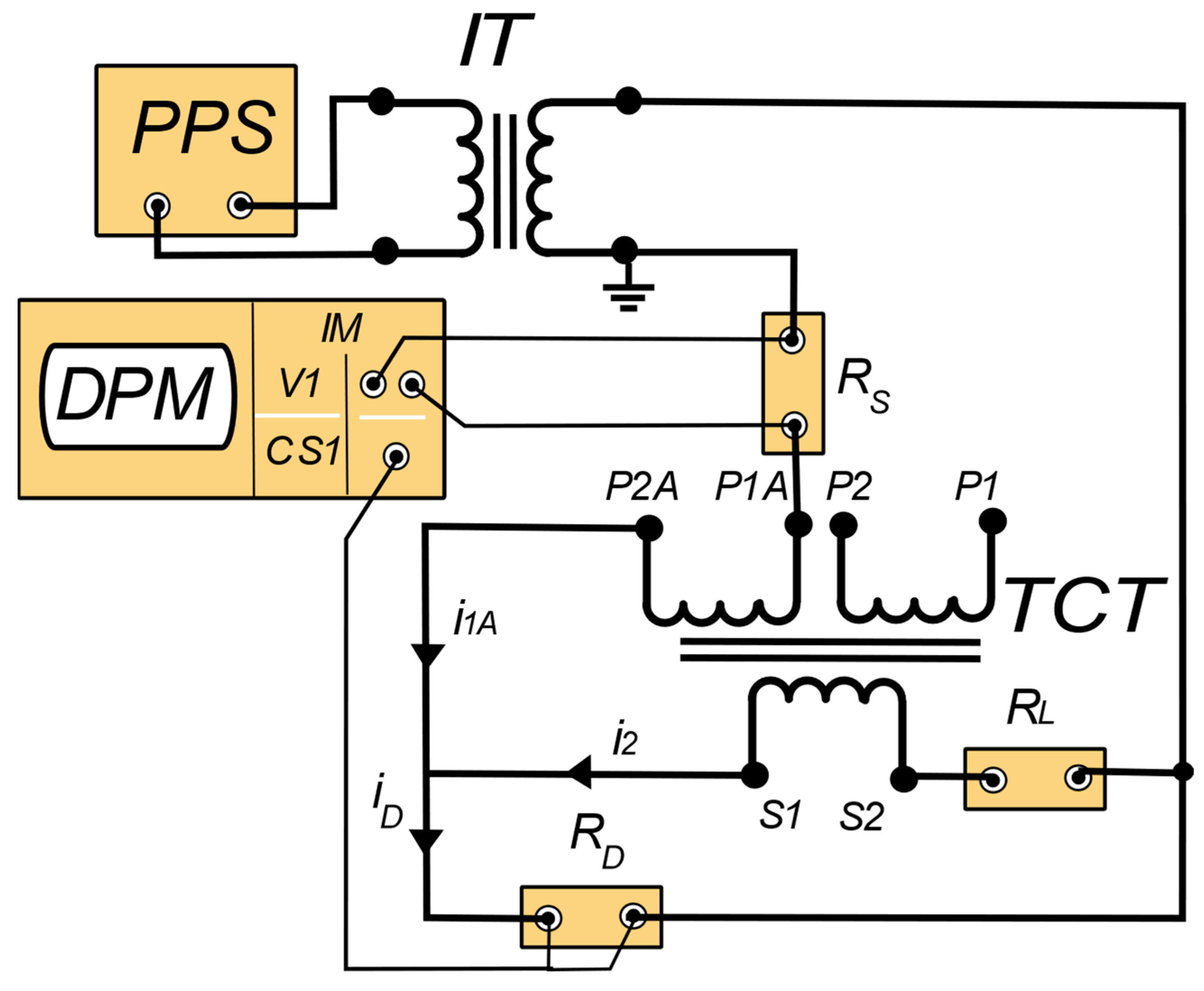
Figure 2.
(a) Vectorial diagram of the instrument transformer, (b) conversion of a low value of the phase angle into a vector of the phase displacement, (c) vectorial diagram of the instrument transformer considering performed conversion. Δφhk—the value of the phase angle between hk harmonic of the secondary current and hk harmonic of the converted to the secondary side primary current of the current transformer, ϕhk—the value of the phase angle between hk harmonic of the composite error and hk harmonic of the converted to the secondary side primary current of the current transformer.

Figure 3.
Comparison of determined values of the current error (a) and phase displacement (b) for both tested CTs up to 10th higher harmonic and rated load of the secondary winding.
Figure 3.
Comparison of determined values of the current error (a) and phase displacement (b) for both tested CTs up to 10th higher harmonic and rated load of the secondary winding.

Figure 4.
Comparison of determined values of the current error (a) and phase displacement (b) for both tested CTs up to 100th higher harmonic and rated load of the secondary winding.
Figure 4.
Comparison of determined values of the current error (a) and phase displacement (b) for both tested CTs up to 100th higher harmonic and rated load of the secondary winding.
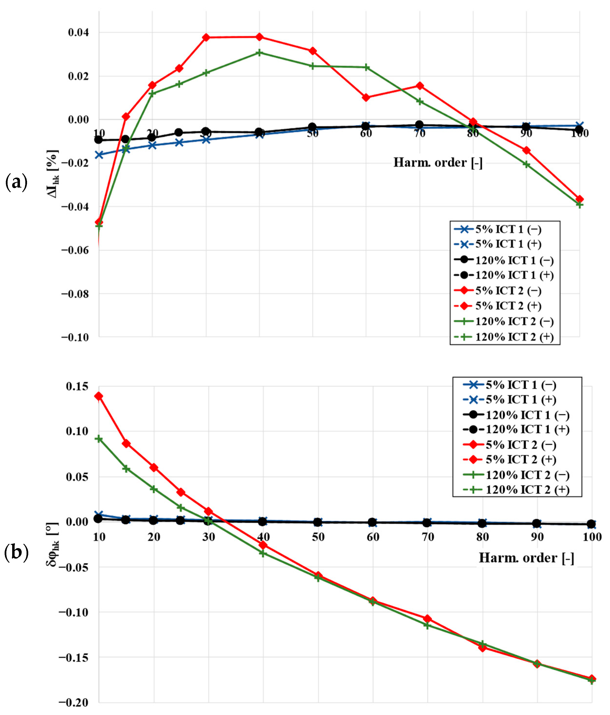
Figure 5.
Comparison of determined values of the current error (a) and phase displacement (b) for both tested CTs up to 10th higher harmonic and 25% of the rated load of the secondary winding.
Figure 5.
Comparison of determined values of the current error (a) and phase displacement (b) for both tested CTs up to 10th higher harmonic and 25% of the rated load of the secondary winding.
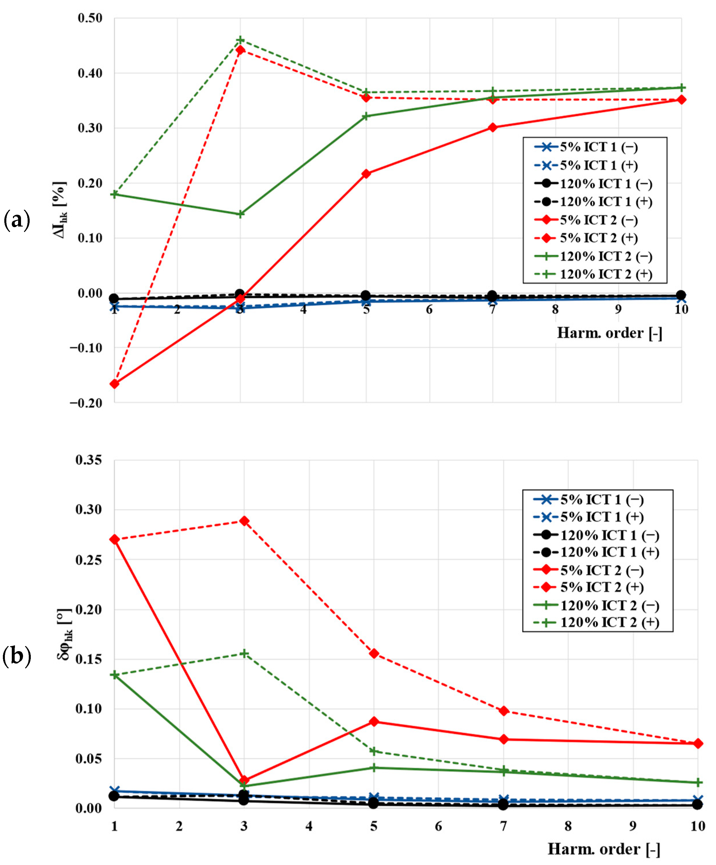
Figure 6.
Comparison of determined values of the current error (a) and phase displacement (b) for both tested CTs up to 100th higher harmonic and 25% of the rated load of the secondary winding.
Figure 6.
Comparison of determined values of the current error (a) and phase displacement (b) for both tested CTs up to 100th higher harmonic and 25% of the rated load of the secondary winding.

Figure 7.
Comparison of determined values of self-generated low-order higher harmonics for both tested CT for rated (a) and 25% (b) of the rated load of the secondary winding.
Figure 7.
Comparison of determined values of self-generated low-order higher harmonics for both tested CT for rated (a) and 25% (b) of the rated load of the secondary winding.

Publisher’s Note: MDPI stays neutral with regard to jurisdictional claims in published maps and institutional affiliations. |
© 2022 by the authors. Licensee MDPI, Basel, Switzerland. This article is an open access article distributed under the terms and conditions of the Creative Commons Attribution (CC BY) license (https://creativecommons.org/licenses/by/4.0/).
Share and Cite
MDPI and ACS Style
Stano, E.; Kaczmarek, P.; Kaczmarek, M. Why Should We Test the Wideband Transformation Accuracy of Inductive Current Transformers? Energies 2022, 15, 5737. https://doi.org/10.3390/en15155737
AMA Style
Stano E, Kaczmarek P, Kaczmarek M. Why Should We Test the Wideband Transformation Accuracy of Inductive Current Transformers? Energies. 2022; 15(15):5737. https://doi.org/10.3390/en15155737
Chicago/Turabian StyleStano, Ernest, Piotr Kaczmarek, and Michal Kaczmarek. 2022. "Why Should We Test the Wideband Transformation Accuracy of Inductive Current Transformers?" Energies 15, no. 15: 5737. https://doi.org/10.3390/en15155737
Note that from the first issue of 2016, this journal uses article numbers instead of page numbers. See further details here.