Article

Experimental Study and Numerical Simulation of an Electrical Preheating for SAGD Wells in Heavy Oil Reservoirs

1
Research Institute of Petroleum Exploration and Development, PetroChina, Beijing 100083, China
2
State Key Laboratory of Enhanced Oil Recovery, PetroChina, Beijing 100083, China
3
Xinjiang Oilfield Company, Petrochina, Karamay 834000, China
4
School of Energy Resources, China University of Geosciences (Beijing), Beijing 100083, China
*
Author to whom correspondence should be addressed.
These authors contributed equally to this work.
Energies 2022, 15(17), 6102; https://doi.org/10.3390/en15176102
Submission received: 8 June 2022 / Revised: 26 July 2022 / Accepted: 11 August 2022 / Published: 23 August 2022
(This article belongs to the Special Issue Advances of Enhanced Oil Recovery Theory and Method)

Abstract

:
It is necessary to establish effective communication between two horizontal wells during the preheating period of steam-assisted gravity-drainage (SAGD). However, the preheating time is usually very long, which results in high steam consumption and CO2 emissions. There is little research on the effects of different wellbore fluids during the preheating period. The heat transfer and heating characteristics of different wellbore fluids–water, heat-conduction oil, and air–were explored by using physical experiments and numerical simulations. In this study, the results indicated that the heat-transfer performance of heat-conduction oil is the best. The numerical simulation’s results indicated that compared with the wellbore saturated with water, the heat-conduction oil reduced the viscosity of crude oil, and energy consumption was not obvious during the preheating stage. The super-heavy oil flowed into the wellbore due to the solubility of the heat-conduction oil and its own gravity. As a result, the super-heavy oil content in the wellbore gradually accumulated, increasing the risk of coking. Those experiments showed that the use of electrical heating provides good potential to improve SAGD efficiency during the preheating period, and water is the best injection fluid for wellbores during the electrical heating process.

1. Introduction

Heavy oil is a kind of crude oil with high viscosity and content of asphalt and resin. Global heavy oil production has continued to grow, which has recently attracted attention to bitumen and heavy oil reservoirs with a high initial viscosity [1]. The high viscosity of heavy oil is the key obstacle to developing this type of reservoir. Thermal EOR methods (enhanced oil recovery) are the main traditional heavy oil development technique. Steam-assisted gravity-drainage (SAGD) technology with dual horizontal wells was proposed in 1981 and has been used to accelerate the rate of heavy oil production [2]. During the SAGD processes, a horizontal production well is typically drilled close to the bottom of the reservoir, and the steam is exploited as a heating medium and continuously injected by a parallel horizontal well above [3]. Okassa et al. (2010) confirmed the effectiveness of electromagnetic heating, resolved the problem of continuous high temperatures in the electromagnetic heating process, and demonstrated, through physical experiments, that electromagnetic technology is a practical method regardless of high- or low-power heating methods [4]. Gasbarri et al. (2011) conducted research on the bottom-hole electrical heating technology for ultra-heavy oil reservoirs [5]. They tested 24 different methods of electrical heating using a horizontal-well, physical simulation experimental device. The study results showed that the bottom-hole electrical heating of heavy oil could effectively improve the oil recovery rate by 60%. Peraser (2012) researched the enhanced oil recovery mechanism of SAGD in dual-horizontal wells supported by non-condensate gas and electrical heating [6]. A two-dimensional physical simulation experimental device was created, and tests of non-condensate gas and electrical-heating-assisted dual-horizontal wells and the conventional SAGD tests were conducted. The recovery factors of the two development methods were compared, and the research results showed that the crude oil recovery rate increased by 8% as compared with conventional SAGD. Zhong et al. (2015) proposed the CSEAGD (CO2 sequestration and electrical-heating-assisted gravity-drainage) approach to amplify heavy oil production [7]. It is understood from the experimental and numerical simulations that CSEAGD is more attainable for heavy oil production. Accordingly, 3–5 PV CO2 could be sequestrated in place depending on the reservoir’s condition and input of more than 1.0 MW of electrical power. Ma et al. (2017) conducted research on solvent- and electrical-heating-assisted SAGD to develop super-heavy oil reservoirs [8]. The authors integrated the kinetic model into the reservoir simulation model to draw out the hydrothermal decomposition and thermal cracking effects on heavy oil under reservoir conditions. Solvent- and water-assisted-electrical-heating modeling of oil sand reservoirs with shale interlayers was conducted. The results of the study showed that the productivity of SAGD was greatly affected by the shale layers. The oil production rate of solvent- and water-assisted-electrical-heating was relatively fixed, and there was no obvious modification in the production cycle.
SAGD production process has four stages: circulation preheating, steam chamber rising, steam chamber spreading and steam chamber descending [9,10]. During the steam-circulation preheating stage, it is essential to preheat the formation of steam circulation and to initiate effective thermal hydraulic connectivity between the two horizontal wells [11,12,13,14]. However, the preheating time usually lasts for more than 6 months, which results in high steam consumption and CO2 emissions [14]. The cost of circulation preheating is economically unfeasible and not an environment–friendly application [15,16]. Refining the economic efficiency of the circulation preheating process has become a popular topic of research. An economical method is necessary to reduce the time to warm up the formation and effectively establish well communication [17]. To solve these problems, Yuan et al. (2004) created the study of fluid-assisted electrical heating in wellbores and simulated and forecasted the effect of electrical-heating-assisted SAGD start-up preheating through a numerical simulation [18]. The results showed that brine injection into the wellbore contributes to uniform electrical heating. SAGD’s electrical-heating-assisted start-up preheating effectively reduced steam consumption. Parmar et al. (2009) provided a sensitivity analysis of the effects of steam circulation rates, pressure differences, and circulation time on preheating time [7]. Zhu and Zeng (2012) managed a study on solvent-electrical-heating-assisted SAGD [19]. Through the combination of physical simulation experiments and CMG numerical simulations, solvent-electrical-heating-assisted SAGD studies were presented. The numbers indicated that the use of a solvent combined with electrical heating could increase the recovery of heavy oil by 20–50%. Xi et al. (2017) used numerical simulation methods to study the start-up preheating stage of dual-level SAGD [20]. The research hinted that effective electrical heating could preheat 90% of the horizontal wells. The SAGD preheating time was reduced from 220 to 90 days. The cost of the SAGD preheating phase of a pair of horizontal wellls has dropped from USD420,000 to 220,000.
The preceding studies have revealed the main mechanisms of electrical heating performances during the preheating processes of SAGD. In general, the previous research on the SAGD preheating stage was mainly focused on steam-cycle preheating technology, using numerical simulation methods to optimize the heavy oil reservoir parameters such as steam injection rate, injection timing, bottom-hole pressure difference, or changed oilfield production work system, so as to carry out the purpose of optimizing the preheating stage [21]. The electrical-heating-assisted SAGD preheating start-up could effectively decrease the consumption of steam [22]. Compared with injecting solvents and other methods, electrical heating can uniformly heat heterogeneous oil reservoirs [23]. However, most scholars have used numerical simulation for the start-up method of electrical-heating-assisted preheating, and there have been few experimental studies on the SAGD preheating stage. There is no research on the influence of wellbore fluid on electrical heating, which may improve the heat transfer productiveness of electrical heating, better the preheating effect of electrical heating, and perfect the economic benefit. In this study, the heat transfers and heating characteristics of different wellbore fluids—water, heat-conduction oil, and CO2—were examined by using physical experiments and numerical simulations, and the optimal wellbore injection fluid for electrical-heating-assisted SAGD was chosen. Meanwhile, the heating characteristics of electrical experiments were successively implemented with an experimental device using an actual wellbore. The heavy oil samples were selected from a typical super-heavy oil reservoir with the SAGD project in the Xinjiang oilfield, China. The heating mechanisms were discussed and determined, and a suggestion that electrical preheating is an adequate candidate to further the efficiency of the preheating process of SAGD in developing heavy oil reservoirs.

2. Experiments for the Heat Transfer of Wellbore Fluids

2.1. Experiments Materials

The main experimental materials are as follows:
Full horizontal well model: The well was 7 in wide and 80 cm long; the maximum pressure resistance was 10 MPa; the highest modeling temperature was 400 °C, and it had a sand-filling function.
Heat-conduction oil: L-QC350 heat-conduction oil was chosen. The highest working temperature of L-QC350 is 350 °C.
CO2: The purity of CO2 was 99%.
Water: The formation water was prepared according to the salinity and mineral composition, in which the salinity was 4970.24 mg/L.

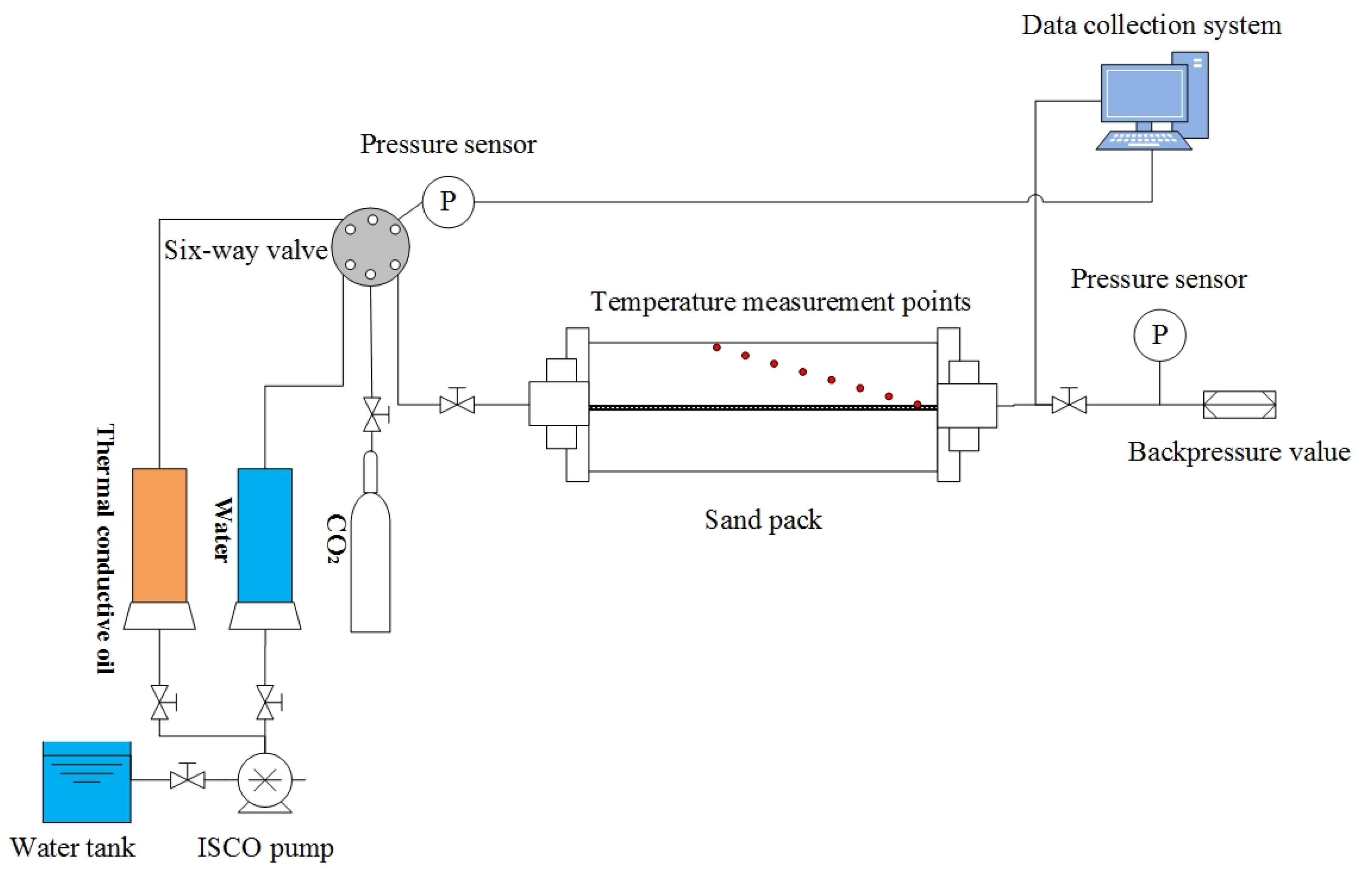
2.2. Experimental Apparatus

Figure 1 shows the experimental apparatus for SAGD electrical preheating for wellbore fluid optimization. The main experimental system is as follows.
The apparatus was mainly composed of an injection system, sand pack, and temperature data acquisition equipment. The injection system mainly included a high-pressure CO2 bottle, gas controller, and ISCO pump. Heat-conduction oil and CO2 could be injected into the sand pack. The temperature data acquisition equipment mainly included a temperature sensor system and computer equipment. The seven temperature measuring points are equally spaced and distributed between the surface of the heater and the pipe of the sand pack. The computer equipment monitored and recorded temperature changes in the sand pack over time. The sand pack was located in the insulation sleeve to heat and compensate for the heat loss and maintain the targeted temperature. There were pressure sensors on the inlet and outlet sections of the sand pack, which were connected to the data acquisition system and used to measure and record the pressure across the sand pack in real-time.

2.3. Experimental Procedures

These experiments were based on an industry-standard set by Sinopec, China. The procedures are briefly described as follows.
(1)
Before the experiment, the sand wellbore was packed with quartz sand.
(2)
The wellbore was saturated with water under 5.82 MPa of pressure.
(3)
The heater’s surface temperature was set to 300 °C, and then the heater was turned on for 5 days.
(4)
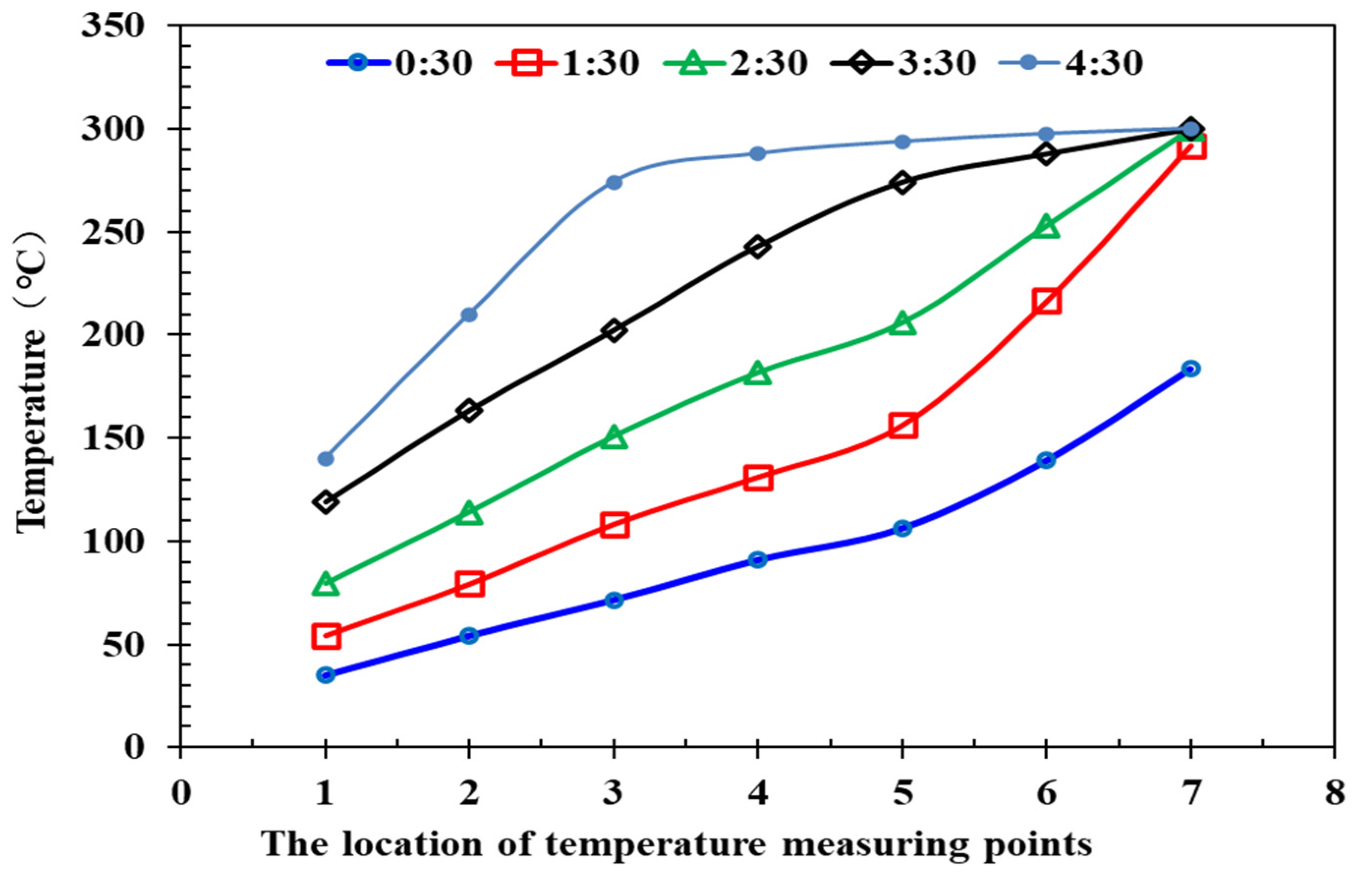
The temperature changes detected by the 7 temperature measurement points in the sand pack were measured and calculated by temperature data acquisition equipment.

2.4. Results and Discussion

Figure 2 shows the heat transfer characteristics of the model while injecting CO2. As shown in Figure 2, after four-and-a-half hours of heating, the temperature in the sand-filling tube increased with time, and the heating rod had a very limited working distance. The final temperature of the No.7 temperature measurement point, which was the nearest to the heating rod, was 350 °C, while the adjacent No.6 temperature measurement point was 172 °C, while the No.1 temperature measurement point, which was the furthest from the heating rod, was only 97 °C. It could be inferred that under sand-filling conditions, the temperature of the reservoir was low because the mass transfer rate and heat convection effect between the hot and cold gases in the porous medium were both slowed down. The heating mainly depended on heat transfer. At the same time, because of the obvious gas insulation characteristics, it was not conducive to heat transfer.
Figure 3 shows the heat transfer characteristics of the model when injecting water. As shown in Figure 3, after four-and-a-half hours of heating, the temperature in the sand-filling tube increased with time. The final temperature of the No.7 measurement point, which was the nearest to the heating rod, was 210 °C, while the adjacent No.6 measurement point was 158 °C, while the No.1 measurement point, which was the furthest from the heating rod, was 117 °C. It can be inferred from these experiments that the heat transfer effect of water is much greater than that of gas, and the convection heat transfer between water molecules is fast, so the heating tube had a wider range while water was injected. The sand-filled tube heater had been heated at full power, but the surface of the heater dissipated quickly, and the surface only reached 210 °C after 4 h of heating, which did not reach the set temperature of 350 °C.
Figure 4 shows the heat transfer characteristics of the model while injecting heat-conduction oil. As shown in Figure 4, the temperature in half of the area had reached 290 °C after 4 h of heating because thermal oil has the best heat transfer performance. Therefore, after the heat-conduction oil was injected, the heating range of the heating rod in the sand-filling pipe was the widest. However, the cost of heat-conduction oil is relatively high, and it must be combined with costs on-site. In summary, the heat transfer performance of thermal oil is the best, the thermal conductivity of water is second, and the thermal conductivity of CO2 is the worst.

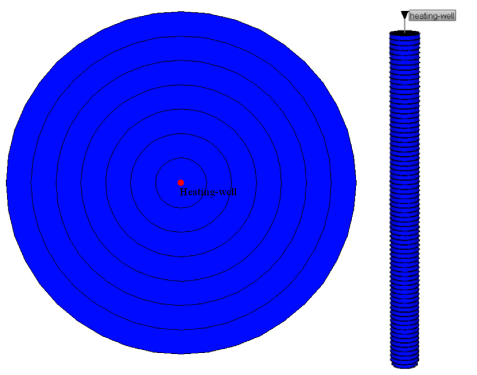
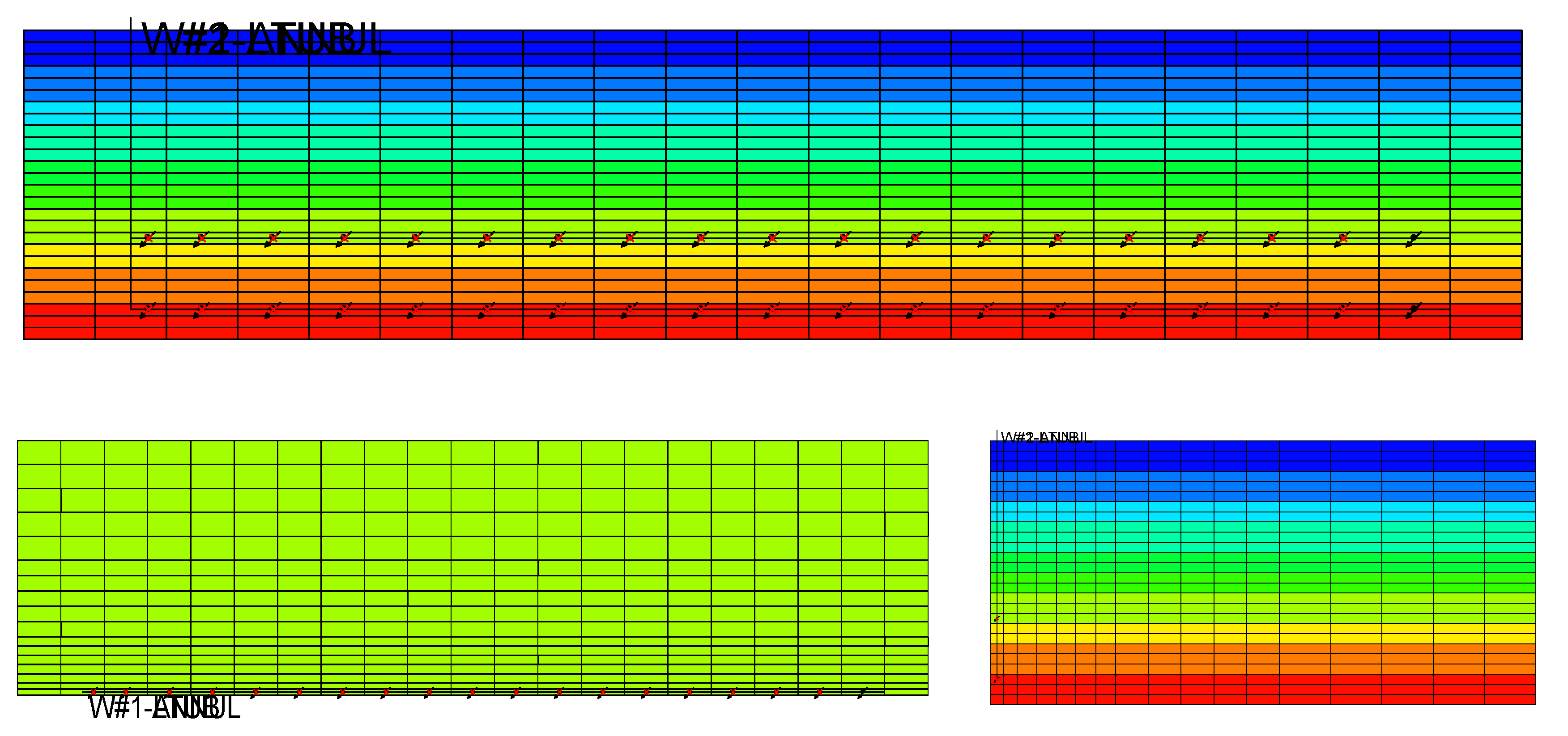
3. Numerical Simulation

To study the effect of heat-conduction oil and water injection on SAGD electrical preheating processes in heavy oil reservoirs, CMG software was used for numerical simulation. A laboratory-size radial model of 7 × 1 × 80 was established by CMG-STARS multi-component thermal recovery numerical simulation software. The experimental scale of the mechanism model is shown in Figure 5, and the parameters are shown in Table 1.
As shown in Figure 6, Figure 7 and Figure 8, after fitting the heat transfer effect of different saturated media, it was found that the difference in temperature between the physical and fitting tests was small, indicating that the experimental calculation parameters were accurate. The parameter values used in the final calculation are shown in Table 2.
Table 3 lists the key parameters of the reservoir. The dimensions of the model were 48 × 119 × 46, and the block size was 10, 1, and 1 m for DX, DY, DZ, respectively. SAGD-production wells were arranged 2.0 m away from the bottom of the oil layer, and the vertical distance between steam injection wells and production wells was 5.0 m. The length of the horizontal well was 500.0 m, and the well group’s spacing was 80.0 m. The heating cable control mode was consistent with the actual control box, and it adopted a dual-control mode that simultaneously controlled the power per meter (constant power mode) and the heater surface temperature (constant temperature mode). The injection and production wellbore’s saturated fluids were set to inject water and heat-conduction oil. The results of the numerical simulation are shown in Figure 9.
Figure 10 shows the oil viscosity between the injection and production well. As shown in Figure 10, when wellbores were saturated with water, the oil viscosity recovery between injection and production well was 89 mPa.s after preheating 300 days, which is similar to 85 mPa.s when wellbores were saturated with heat-conduction oils. The experiment’s results showed that compared with the wellbore saturated with water, heat-conduction oil could not obviously reduce the viscosity of crude oil during the preheating stage. The reason was that although the heat-conduction oil has excellent wellbore heat-conduction effects, when the average injection volume of IP wells was as high as 200 tons, according to the simulation results, it could be seen that the heat-conduction oil spread only 1.5 m in the vicinity of the well at the end of preheating. The effect of accelerating the connection of the interlayer oil was limited.
Figure 11 shows the mole fraction of heat-conduction oil and super-heavy oil changes with time. As shown in Figure 11, on the fifth day, the mole fraction of heat-conduction oil in the wellbore was 0.91, and the mole fraction of super-heavy oil was 0.95. On the ninetieth day, the mole fraction of heat-conduction oil in the wellbore was 0.33, and the mole fraction of super-heavy oil was 0.66. The results indicated that the mole fraction of heat-conduction oil in the wellbore decreased with the increase in heating time, and the mole fraction of super-heavy oil in the wellbore increased with the preheating time increasing because heat-conduction oil has a good ability to dissolve super-heavy oil. The super-heavy oil flowed into the wellbore due to the solubility of the heat-conduction oil and its own gravity. As a result, the super-heavy oil content in the wellbore gradually accumulated, increasing the risk of coking.
Figure 12 shows the comparison of energy consumption during SAGD electrical preheating. As shown in Figure 12, the cumulative energy consumption when water was injected into the wellbore was only 1.5% more than when the heat-conduction oil was injected. The energy-saving effect of heat-conduction oil was not obvious. At the same time, the cost of heat-conduction oil reaches 1800 USD/ton, which is far greater than the cost of water. From the perspective of cost and preheating effects, injecting water into a wellbore is more feasible and economical during the preheating process of SAGD.
In summary, the effect of heat-conduction oil in reducing crude oil viscosity and energy saving was not obvious. At the same time, injecting heat-conduction oil increases the risk of wellbore coking. Therefore, a wellbore is more suitable for saturating with water rather than heat-conduction oil and CO2 in the preheating stage of SAGD.

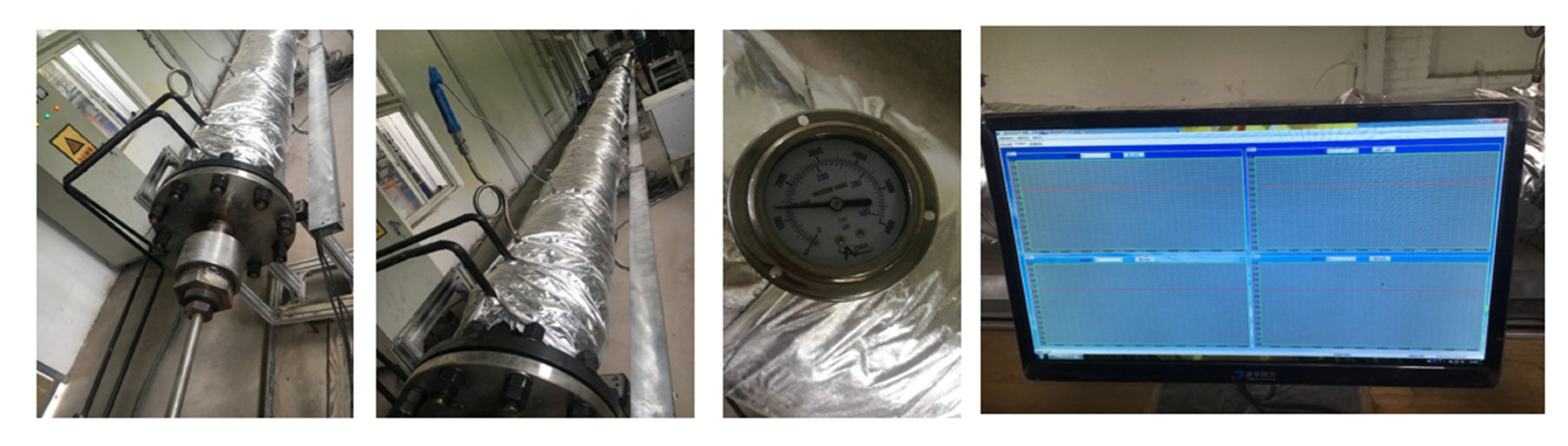
4. Experiments for the Heating Characteristics of Actual Wellbore

The heating characteristics of an actual wellbore saturated with water.The relationship of the formation temperature between the heating time was explored by physical experiments. Figure 13 shows the experimental apparatus of an actual wellbore’s electrical heating characteristics. The main experimental apparatus was as follows.
The apparatus was mainly composed of a wellbore, electrical heater, and temperature data acquisition equipment. The wellbore was 7 in wide and 18 m long; the maximum pressure resistance was 20 MPa, the temperature resistance was 400 °C, and it had 20 temperature and pressure measuring points. Temperature data acquisition equipment monitored and recorded temperature changes in the wellbore over time. The electrical heater had the same specifications as an actual oil field heater, with a diameter of 1.3 in, a power of 1600 W/m, a heating section of 5 m, a transition section of 5 m, and a conductive section of 5 m. The wellbore had a full foundation of water.

4.1. Experimental Procedures

(1)
Before the experiment, the actual wellbore was packed with quartz sand.
(2)
The wellbore was saturated with water under 5.82 MPa of pressure, and the insulation layers outside the wellbore were set to 15 °C, 20 °C, 25 °C, and 30 °C.
(3)
The heater’s surface temperature was set to 300 °C, and then the heater was turned on for 100 h.
(4)
The temperature changes were measured by the 20 measurement points, and the average temperature was calculated by temperature data acquisition equipment.

4.2. Results and Discussion

Figure 14 and Figure 15 show the heating characteristics of the actual wellbore. As shown in Figure 14 and Figure 15, the wellbore quickly heated up in the initial stage. It took longer for the wellbore to reach 300 °C. The higher the foundation temperature, the less time the wellbore took to reach 300 °C. The higher the formation temperature, the shorter the heating time to read 300 °C. When the temperature reached 200 °C, the heating rate slowed down. The original reason was that the heat transfer loss from the wellbore increased. When the foundation temperature was 20 °C, the wellbore temperature reached 300 °C after heating for 98 h. According to the temperature display of the control box, before the temperature in the wellbore reached 300 °C, the total heating power was 2.698 KW; when the temperature of the wellbore reached 300 °C, the total power required to maintain the temperature dropped to 1.868 kW, which was 69.2% of the initial power.

5. Conclusions

Based on the present study, the following conclusions can be drawn:
(1)
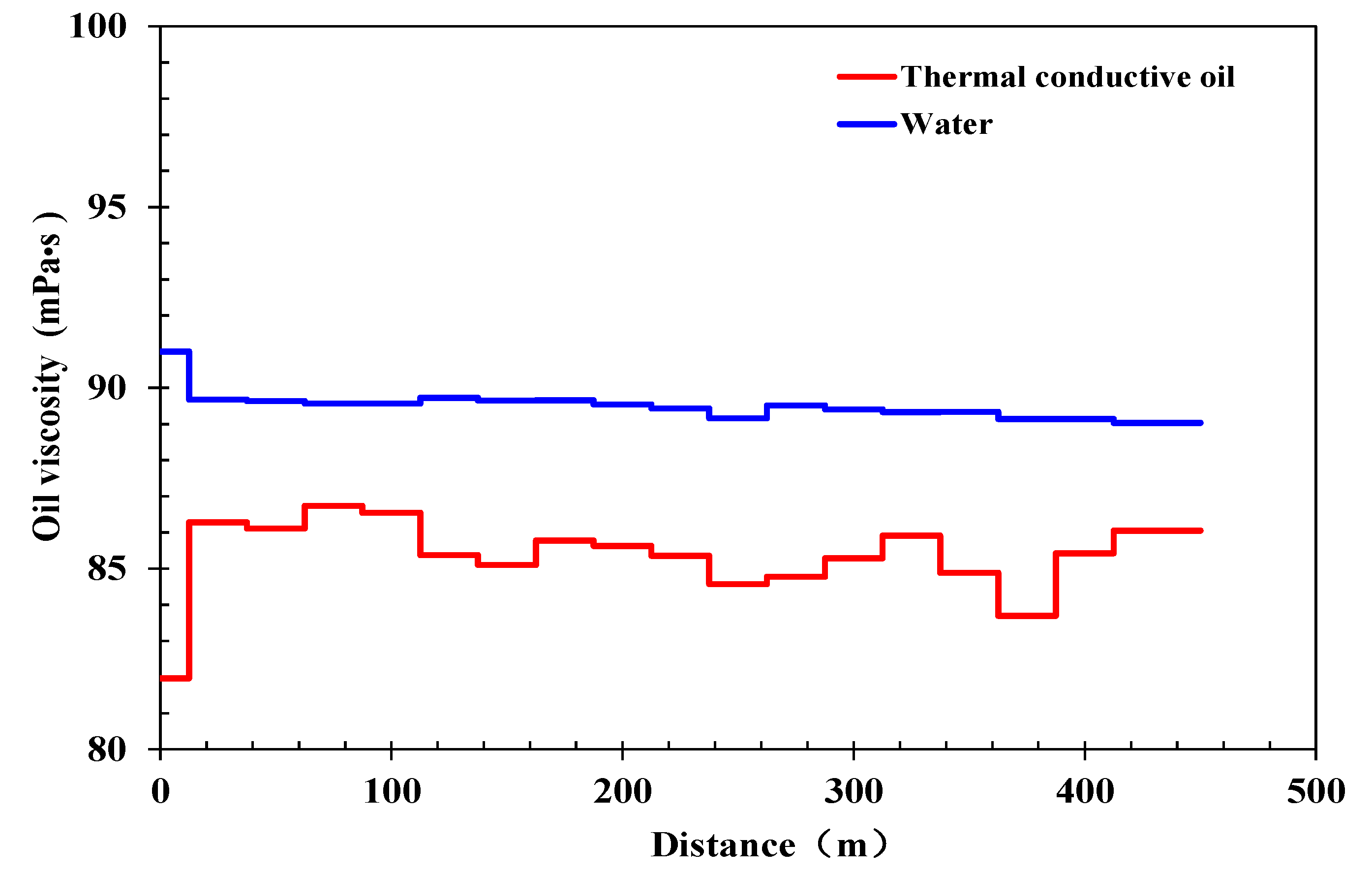
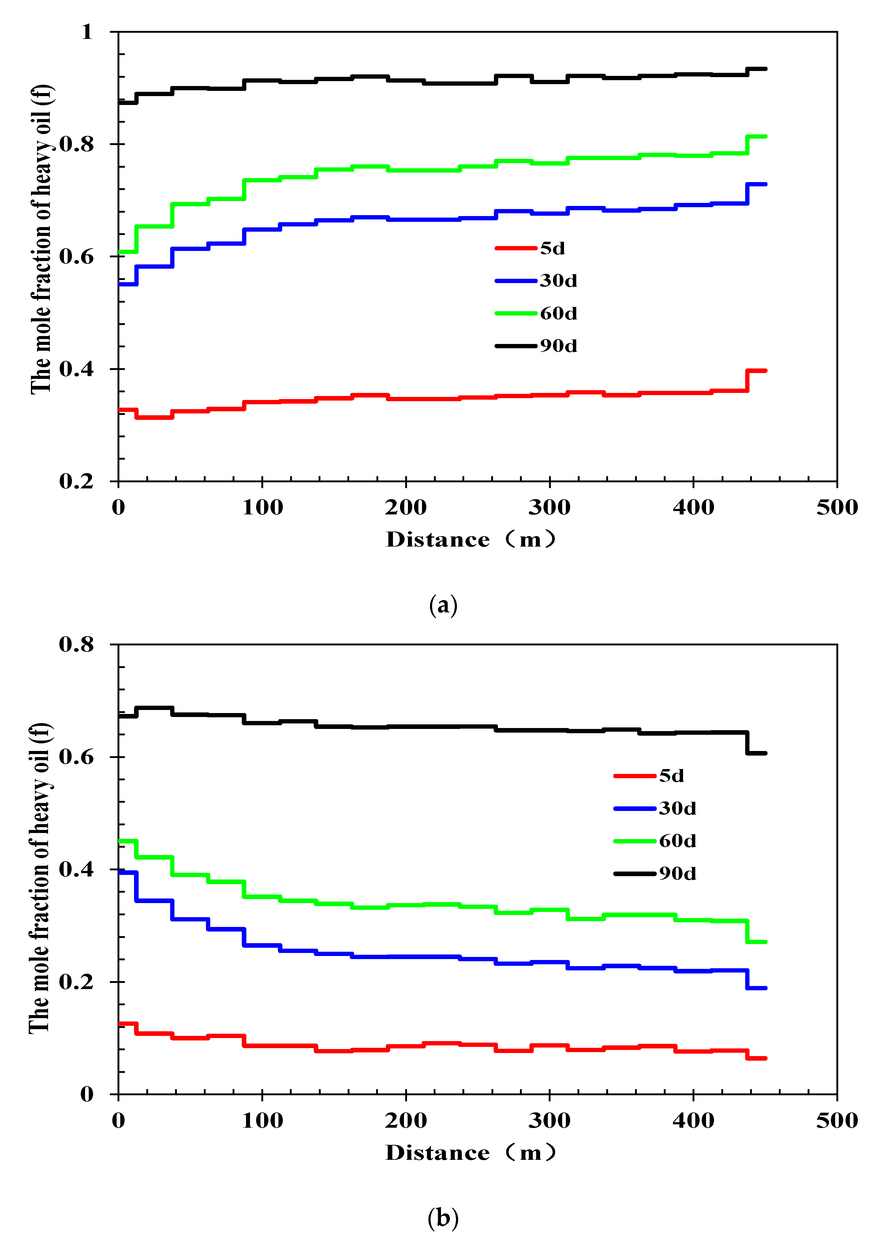
The wellbore in the preheating stage was more suitable for saturation with water rather than heat-conduction oil or CO2. Even though the results of the physical experiments showed that the heat transfer performance of heat-conduction oil is the best, the thermal conductivity of water is second, and the thermal conductivity of CO2 is the worst. Therefore, after the heat-conduction oil was injected, the heating range of the heating rod in the sand-filling pipe is the widest. However, heat-conduction oil and water had a similar effect in reducing the viscosity of heavy oil near the well. According to the results of the numerical simulation experiment, when wellbores were saturated with water, the oil viscosity recovery between injection and production well was 89 mPa.s after preheating 300 days, which is similar to 85 mPa.s when wellbores were saturated with the heat-conduction oil. Because heat-conduction oil has a good ability to dissolve super-heavy oil, the super-heavy oil flowed into the wellbore due to the solubility of the heat-conduction oil and its own gravity. As a result, the super-heavy oil content in the wellbore gradually accumulated, increasing the risk of coking. The cumulative energy consumption of water injected into the wellbore was only 1.5% more than that of the heat-conduction oil injected into the wellbore. Therefore, the wellbore in the preheating stage was more suitable for saturated water rather than heat-conduction oil or CO2.
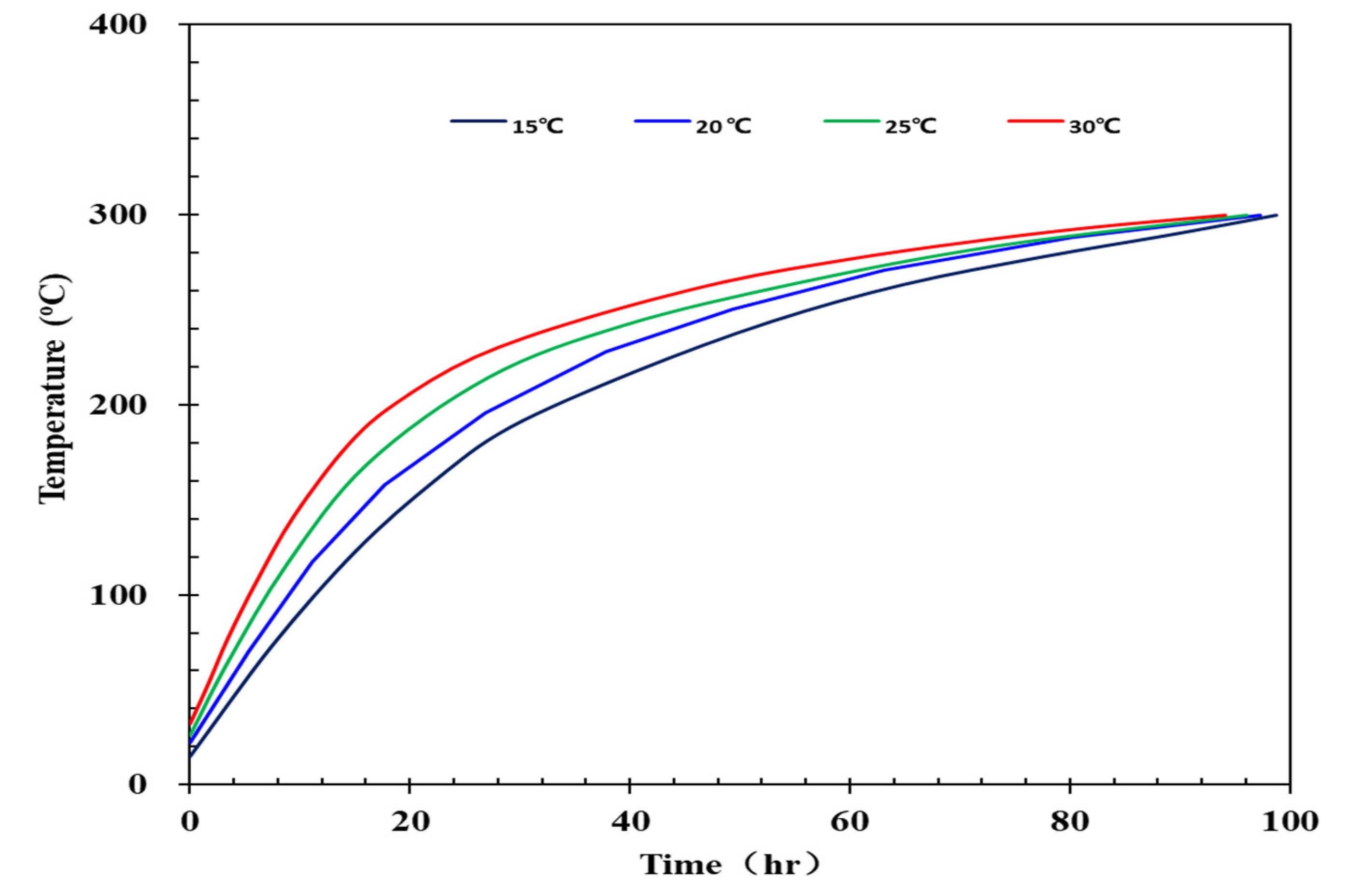
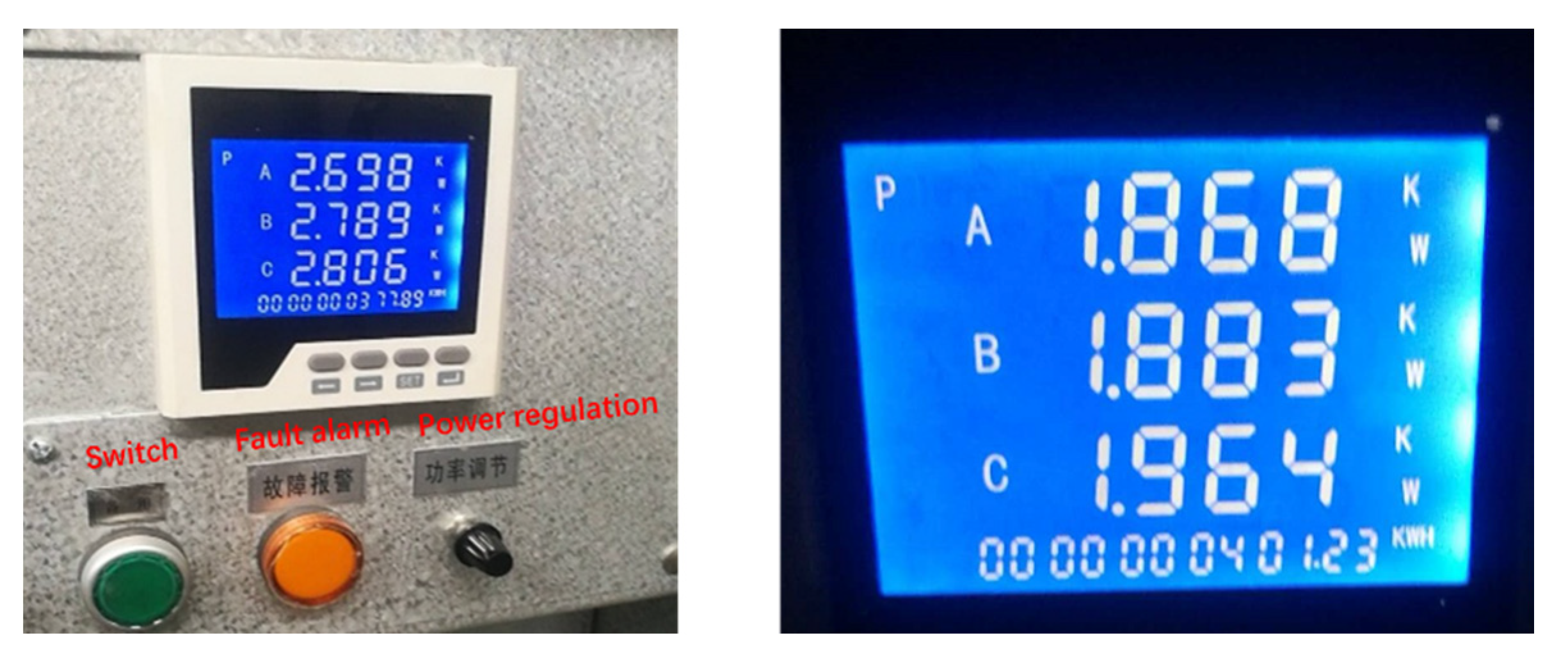
(2)
It took different heating times for the wellbore to reach 300 °C. The higher the foundation temperature was, the less time the wellbore took to reach 300°C. The wellbore heated up quickly in the initial stage. When the temperature reached 200 °C, the heating rate slowed down. The original reason was that the heat-transfer loss from the wellbore increased. After the wellbore was heated for 98 h, the wellbore temperature reached 300 °C. The total heating power was 2.698 KW; when the temperature of the wellbore reached 300 °C, the total power required to maintain the temperature dropped to 1.868 kW, which was 69.2% of the initial power.

Author Contributions

Methodology, Y.W.; investigation, C.L., H.Z.; resources, Y.J.; data curation, C.W.; writing—C.W.; writing—review and editing, Q.W. and J.Z.; supervision, Y.Z.; All authors have read and agreed to the published version of the manuscript.

Funding

This work was financially supported by the National Major Science and Technology Project of China (2016ZX05012-002) and Fundamental Research Funds of the China National Petroleum Corporation (2017D-5008-04).

Institutional Review Board Statement

Not applicable.

Data Availability Statement

Not applicable.

Acknowledgments

Not applicable.

Conflicts of Interest

The authors declare no conflict of interest. The funders had no role in the design of the study, in the collection, analyses, or interpretation of data, in the writing of the manuscript, or in the decision to publish the results.

References

  1. Liu, P.; Zhou, Y.; Liu, P.; Shi, L.; Li, X.; Li, L. Numerical study of herringbone injector -horizontal producer steam assisted gravity drainage (HI-SAGD) for extra-heavy oil recovery. J. Pet. Sci. Eng. 2019, 181, 106227. [Google Scholar] [CrossRef]
  2. Yuan, Z.; Liu, P.; Zhang, S.; Jiao, Y.; Li, X. Experimental study and numerical simulation of a solvent-assisted start-up for SAGD wells in heavy oil reservoirs. J. Pet. Sci. Eng. 2017, 125, 261–268. [Google Scholar] [CrossRef]
  3. Hill, D.G.; Chilingar, G.V.; Wittle, J.K. Direct current electrical enhanced oil recovery in heavy-oil reservoirs to improve recovery, reduce water cut, and reduce H2S production while increasing API gravity. In Proceedings of the SPE 114012, Egional and Pacific Section AAPG Joint Meeting, Bakersfield, CA, USA, 29 March–2 April 2008. [Google Scholar]
  4. Okassa, F.; Godi, A.; de Simoni, M.; Matteo, M.; Misenta, M.; Maddinelli, G. A nonconventional EOR technology using RF/MW heating coupled with a new patented well/reservoir interface. In Proceedings of the SPE 134324: SPE Annual Technical Conference and Exhibition, Florence, Italy, 19–22 September 2010. [Google Scholar]
  5. Gasbarri, S.; Diaz, A.; Guzman, M. Evaluation of electric heating on recovery factors in extra heavy oil reservoirs. In Proceedings of the SPE 149779: SPE Heavy Oil Conference and Exhibition, Kuwait City, Kuwait, 12–14 December 2011. [Google Scholar]
  6. Peraser, V.; Patil, S.L.; Khataniar, S.; Dandekar, A.Y.; Sonwalkar, V.S. Evaluation of electromagnetic heating for heavy oil recovery from alaskan reservoirs. In Proceedings of the SPE 154123: SPE Western Regional Meeting, Bakersfield, CA, USA, 21–23 March 2012. [Google Scholar]
  7. Parmar, G.; Zhao, L.; Graham, J. Start-up of SAGD wells: History match, wellbore design and operation. J. Can. Pet. Technol. 2009, 48, 42–48. [Google Scholar] [CrossRef]
  8. Ma, M.; Faradonbeh, M.R.; Hassanzadeh, H.; Harding, T.G.; Zanon, S. Comparative study of SAGD and solvent and water sssisted wlectrical heating: Effect of shale layers. In Proceedings of the SPE 184997: SPE Canada Heavy Oil Technical Conference, Calgary, AB, Canada, 15–16 February 2017. [Google Scholar]
  9. Shi, L.; Li, X.; Xi, C.; Qi, Z.; Liu, P. Analytical modeling of the oil steam ratio during the lifetime steam-assisted gravity drainage process in extra-heavy oil reservoirs. J. Pet. Sci. Eng. 2021, 203, 108616. [Google Scholar] [CrossRef]
  10. Guo, E.; Jiang, Y.; Gao, Y.; Shen, D.; Zhigang, C.; Yu, P. A new approach to improve recovery efficiency of SAGD. In Proceedings of the SPE 183741: SPE Middle East Oil & Gas Show and Conference, Manama, Bahrain, 6–9 March 2017. [Google Scholar]
  11. Kumar, A.; Hassanzaden, H. Impact of shale barriers on performance of SAGD and ES-SAGD—A review. Fuel 2021, 289, 119850. [Google Scholar] [CrossRef]
  12. Wang, Z.; Gao, D.; Diao, B.; Tan, L.; Zhang, W.; Liu, K. Comparative performance of electric heater vs. RF heating for heavy oil recovery. Appl. Therm. Eng. 2019, 160, 105–114. [Google Scholar] [CrossRef]
  13. Hascakir, B.; Babadagli, T.; Akin, S. Field-scale analysis of heavy-oil recovery by electrical heating. SPE Reserv. Eval. Eng. 2010, 13, 131–142. [Google Scholar] [CrossRef]
  14. Zhong, L.; Yu, D.; Yang, H.; Sun, Y.; Wang, G.; Zheng, J. Feasibility study on produce heavy oil by gas and electrical heating assisted gravity drainage. In Proceedings of the SPE 174406: SPE Canada Heavy Oil Technical Conference, Calgary, AB, Canada, 9–11 June 2015. [Google Scholar]
  15. Zhu, Z.; Zeng, F. Evaluation of the hybrid process of electrical resistive heating and solvent injection through numerical smulations. In Proceedings of the SPE Heavy Oil Conference Canada, Calgary, AB, Canada, 12–14 June 2012. [Google Scholar]
  16. Ghannadi, S.; Irani, M.; Chalaturnyk, R.J. Induction and radio frequency heating strategies for steam-assisted gravity drainage start-Up phase. In Proceedings of the SPE 170037: SPE Heavy Oil Conference-Canada, Calgary, AB, Canada, 10–12 June 2014. [Google Scholar]
  17. Bermúdez, J.; Acosta, W.; Andarcia, L.; Suarez, A.; Vaca, P.; Pasalic, D.; Okoniewski, M. Assisted extra heavy oil sampling by electromagnetic heating. In Proceedings of the SPE 171073: SPE Heavy and Extra Heavy Oil Conference, Latin America, Medellín, Colombia, 24–26 September 2014. [Google Scholar]
  18. Yuan, J.Y.; Huang, H.; Mintz, R.; Wang, X.; Jossy, C.; Tunney, C. Wet electric heating for starting up SAGD/VAPEX. In Proceedings of the Petroleum Society of Canada Canadian International Petroleum Conference, Calgary, AB, Canada, 1–3 August 2004. [Google Scholar]
  19. Vermeulen, F.E.; Chute, F.S.; McPherson, R.G. Physical modelling of electrothermal processes in oil sand. Alta. Oil Sands Technol. Res. J. Res. 1988, 4, 299–305. [Google Scholar]
  20. Xi, C.; Qi, Z.; Jiang, Y.; Han, W.; Shi, L.; Li, X.; Wang, H.; Zhou, Y.; Liu, T.; Du, X. Dual-horizontal wells SAGD start-up technology: From conventional steam circulation to rapid and uniform electric heating technology. In Proceedings of the SPE 189241: SPE Symposium: Production Enhancement and Cost Optimisation, Kuala Lumpur, Malaysia, 7–8 November 2017. [Google Scholar]
  21. Nasr, T.N.; Beaulieu, G.; Golbeck, H.; Heck, G. Novel expanding solvent-SAGD process “ES-SAGD”. J. Can. Pet. Technol. 2003, 42, 13–16. [Google Scholar] [CrossRef]
  22. Rafiee, M.; Behr, A.; Lessner, E.; Diehl, D.; Trautmann, B.; Koch, A. Electromagnetic Heating for Heavy Oil Production: Case Study of a Field Applicability. In Proceedings of the SPE Russian Petroleum Technology Conference, Moscow, Russia, 26–28 October 2015. [Google Scholar]
  23. Ramcharan, T.; Hosein, R.; Jupiter, A. The Viability of oil extraction from trinidad tar sands by radio frequency heating-a simulation approach. In Proceedings of the SPE 180830: SPE Trinidad and Tobago Section Energy Resources Conference, Port of Spain, Trinidad and Tobago, 13–15 June 2016. [Google Scholar]
Figure 1. Schematic apparatus of the heating characteristics of wellbore fluids experiment.
Energies 15 06102 g001
Figure 2. The heat transfer characteristics of model when injecting CO2.
Energies 15 06102 g002
Figure 3. The heat transfer characteristics of model while injecting water.
Energies 15 06102 g003
Figure 4. The heat transfer characteristics of model while injecting heat-conduction oil.
Energies 15 06102 g004
Figure 5. Laboratory-size radial model of electrical heating.
Energies 15 06102 g005
Figure 6. Temperature fitting results of saturated CO2.
Energies 15 06102 g006
Figure 7. Temperature fitting results of water.
Energies 15 06102 g007
Figure 8. Temperature fitting results of heat-conduction oil.
Energies 15 06102 g008
Figure 9. Typical SAGD electrical preheating numerical model.
Energies 15 06102 g009
Figure 10. Oil viscosity between injection and production well.
Energies 15 06102 g010
Figure 11. The mole fraction of heat-conduction and super-heavy oil changes with time. (a) The mole fraction of heat-conduction oil; (b) The mole fraction of heavy oil.
Energies 15 06102 g011
Figure 12. The energy consumption at different temperatures.
Energies 15 06102 g012
Figure 13. The actual wellbore heating experiment.
Energies 15 06102 g013
Figure 14. Wellbore heating characteristic curve.
Energies 15 06102 g014
Figure 15. Three-phase power change of control box.
Energies 15 06102 g015
Table 1. The numerical simulation parameters of CO2, water, and heat-conduction oil.
ComponentThermal Conductivity
CO21.40 × 102
Water1.15 × 104
Heat-conduction oil5.35 × 104
Table 2. The key parameters of the laboratory-size radial model.
Grid Number, /7 × 1 × 80Radial Mesh Width, cm2.54
Grid height, cm1.00Original formation pressure5.82
Formation Temperature, °C20Porosity, f0.3
Permeability, mD2000Oil saturation, f0.7
Table 3. The key parameters of the reservoir.
Top Depth, m300.0Oil Viscosity (@50 °C), mPa·s9 × 104
Thickness, m46.0Permeability, μm23.2
Formation pressure, MPa3.0Porosity, f0.3
Temperature, °C30.0Oil saturation, f0.7
Publisher’s Note: MDPI stays neutral with regard to jurisdictional claims in published maps and institutional affiliations.

