Article

Robust Control and Optimization Method for Single-Phase Grid-Connected Inverters Based on All-Pass-Filter Phase-Locked Loop in Weak Grid

1
School of Electrical Engineering, China University of Mining and Technology, University Road 1, Xuzhou 221116, China
2
School of Electrical Engineering, Shenyang University of Technology, Shen Liao West Road 111, Shenyang 110027, China
*
Authors to whom correspondence should be addressed.
Energies 2022, 15(19), 7355; https://doi.org/10.3390/en15197355
Submission received: 15 August 2022 / Revised: 9 September 2022 / Accepted: 4 October 2022 / Published: 6 October 2022

Abstract

:
In a distributed generation system, the all-pass-filter phase-locked loop (APF-PLL) is a commonly used method for grid synchronization. However, the coupling effect between APF-PLL and current control loop increases the risk of oscillation instability for the inverter in the weak grid. At present, there are few effective methods to solve the adverse effect of APF-PLL on the inverter-grid interconnection system in the weak grid. Therefore, a small-signal impedance model of the inverter considering the dual d-q frame brought by APF-PLL is first established. Then the reason for the inverter instability caused by APF-PLL in the weak grid is analyzed. Subsequently, an impedance reshaping method based on a modified first-order filter PLL with a complex coefficient filter (CCF-MFOF-PLL) and its parameter optimization design method are proposed. Finally, the experimental results verify that the proposed method widens the stable range of the inverter and ensures the stable operation of the inverter even with the large grid impedance.

Graphical Abstract

1. Introduction

Global environmental pollution and the energy crisis have greatly promoted the development of distributed generation technology [1,2]. As the power interface between distributed energy and power grid, the GCI plays a vital role in feeding the renewable energy output to the grid [3]. In order to control the power delivered to the grid by the inverter, PLL is often used to obtain the synchronization information of grid voltage [4]. However, the dynamic characteristic of PLL in the weak grid brings an angular deviation between the control and system d-q frame in the small-signal perturbation state, which in turn deteriorates the operating environment of the grid-connected system through the current controller [5]. Meanwhile, with the deepening of the weak grid degree, the coupling between PLL, current controller and the power grid is gradually strengthened, which brings adverse influence to the stability of the grid-connected system [6,7].
In current studies, there are two types of methods regarding the stability analysis and control of GCI in the weak grid. One category is the method considering the influence of PLL, and the other category is the method without considering the influence of PLL. To improve the robustness of GCI to the grid, some robust or adaptive control methods are proposed, such as robust active damping and current control methods [8,9,10], robust grid voltage feedforward control methods [11,12,13], adaptive methods based on feedback loop [14], and so on. In fact, it is reasonable to ignore the PLL when the research mainly focuses on the output characteristic of GCI at the high-frequency band, which is much larger than the bandwidth of PLL. In the case of an extremely weak grid, where the equivalent impedance of the grid is large, the frequency point at which oscillation instability occurs is close to the bandwidth of PLL. At this time, the effect of PLL must be considered when analyzing the stability of the grid-connected system.
In terms of inverter stability analysis considering the influence of PLL, scholars worldwide have conducted a lot of research. The influence mechanism caused by the synchronous reference frame PLL (SRF-PLL) on the inverter stability is studied in [15], which shows that PLL is required to achieve the strong attenuation characteristic at the low-frequency band and suppress the adverse effect of PLL. Then a decoupling method combined with the grid measurement is proposed in [16], which can reshape the input signal of SRF-PLL and thus weaken the negative phase shift brought by PLL. However, this method relies on the accuracy of the impedance measurement, which causes the inverter to become unstable when the system is under faulty working conditions. In [17], an improved voltage feed-forward control method for GCI is proposed to reduce the influence of PLL, but the optimal design principle for the inverter control parameters is not redesigned when the control structure is altered. A conservative design method for PLL parameters with the bandwidth and system phase margin as constraints is proposed in [18], which improves inverter stability, but this is at the expense of current dynamic tracking performance. Then two impedance reshaping methods in the q-axis for the GCI are proposed in [19,20]. However, the specific stability region extension scope of these methods is not clear. In [21], the influence of the proportional gains of SRF-PLL and dc-link voltage loop on the inverter stability is analyzed, based on which an improved voltage feedback control method is proposed. However, this method increases the complexity of the system, which in turn destroys the dynamic response speed for GCI to a certain extent. In [22], the stability margin of the inverter is improved by designing a phase angle compensation link of SRF-PLL, but this method cannot adapt to the wide frequency variation in the grid impedance and it also increases the complexity of the system control. In [23], three types of improved SRF-PLL structures based on the pre-filter are proposed to suppress the adverse effect of SRF-PLL on inverter stability. The analysis shows that the CCF-based SRF-PLL has better dynamic characteristic than the band-pass and low-pass filter-based SRF-PLL, which also require no additional phase compensation link. Based on this research, in this paper the CCF-based pre-filter structure is extended to the single-phase APF-PLL to study its optimization role on the operating characteristic of GCI and its adaptation to grid impedance in the weak grid.
With the above analysis, a small-signal control model for a single-phase LCL-type inverter considering the influence of APF-PLL is taken as the basis for the research. The GCI with an APF-PLL based on CCF is obtained by attaching CCF to the pre-stage of APF-PLL. On the one hand, the addition of the CCF can reshape the output impedance of GCI, thus improving the output characteristic of the inverter in low-frequency band and its adaptability to the weak grid. On the other hand, the CCF as the pre-stage structure is more conducive to the extraction of the grid fundamental frequency by the back-stage APF-PLL in the case of grid impedance perturbation, which in turn improves the stability of the GCI in the weak grid. In addition, a parameter optimization design method for CCF-MFOF-PLL is given, which simultaneously takes into account the constraints of the performance for PLL and the stability domain for GCI, thus enhancing the adaptability of GCI to the weak grid. Finally, the experimental results verify the correctness of the theoretical analysis in this paper.
The rest of this paper is organized as follows. In Section 2, a small-signal impedance model and stability of the inverter are analyzed. Then, an impedance reshaping method for GCI based on CCF-MFOF-PLL and its parameter design method are proposed in Section 3. Moreover, the effectiveness of the proposed control method is verified through experimentation in Section 4. Finally, the conclusion is drawn in Section 5.

2. Stability Analysis for GCI Considering MFOF-PLL

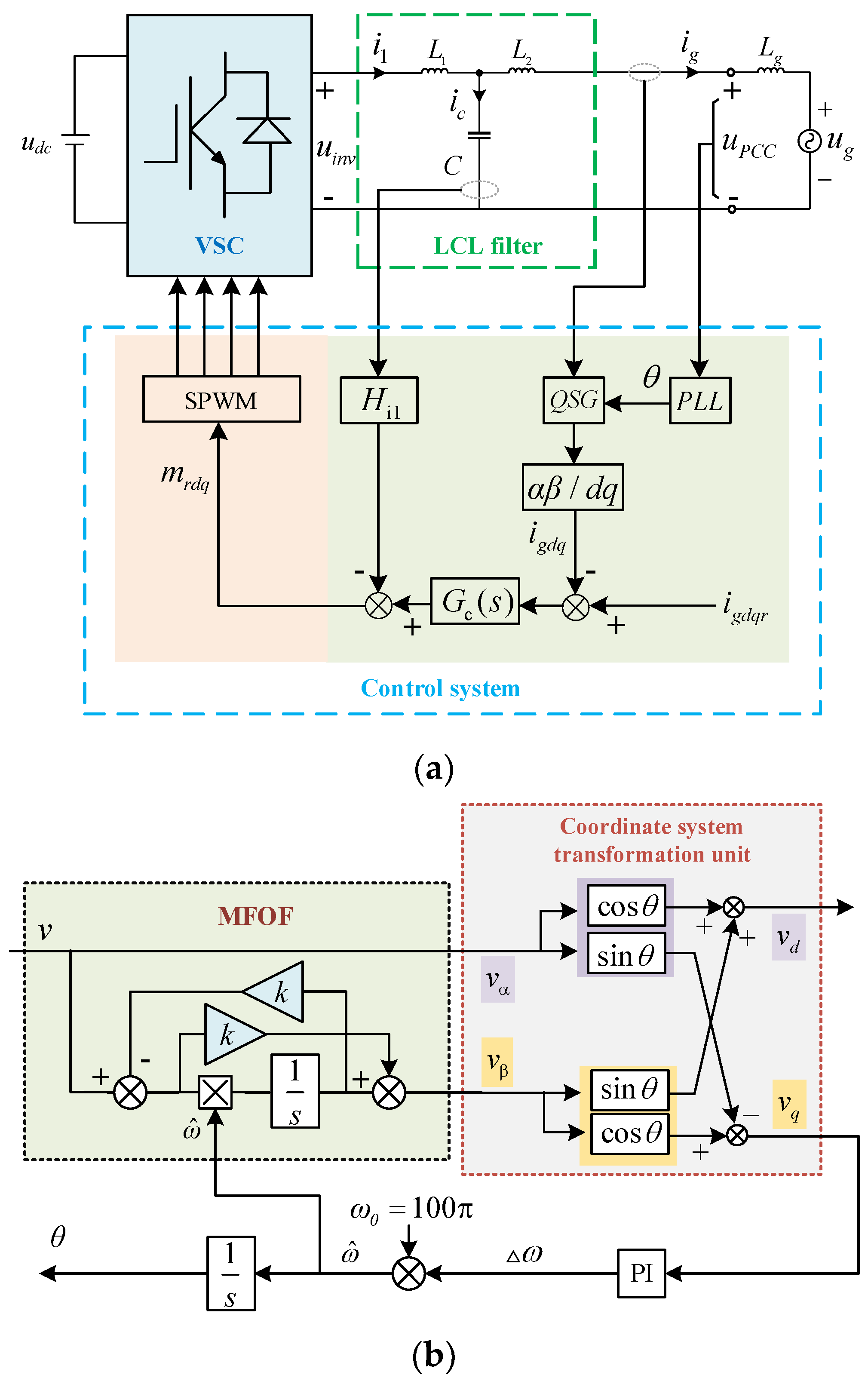
2.1. Small-Signal Impedance Model of the Inverter under Multiple Perturbation

Figure 1a shows the control block diagram of the single-phase LCL-type grid-connected inverter, where L1 denotes the inverter-side inductor, C denotes the filter capacitor, L2 denotes the grid-side inductor, and Hi1 denotes the active damping factor. In this paper, a modified first-order filter (MFOF) proposed in [24,25,26] is chosen as the quadrature signal generator (QSG) of the inverter, which is a type of improved APF-PLL. The control diagram of MFOF-PLL is shown in Figure 1b. To improve the stability of the inverter in the weak grid, the harmonic resonance controller Gc(s) with phase compensation link proposed in [27] is used as the current controller for the inverter.
Due to the dynamic characteristic of the PI controller in MFOF-PLL, there is an angular deviation Δ θ between the control d-q frame and system d-q frame in the small-signal perturbation state. Considering the effect of small-signal perturbation, the variables in dual d-q frame can be expressed as [28]:
[ Δ x d s Δ x q s ] = [ Δ x d c Δ x q c ] + [ 0 H PI ( s ) x q s s + H PI ( s ) U P C C 0 0 - H PI ( s ) x d s s + H PI ( s ) U P C C 0 ] [ Δ u P C C d s Δ u P C C q s ]
where, the variables in the system d-q frame and control d-q frame are defined as xs and xc, respectively. The symbol Δ x denotes the small-signal variable in d-q frame, H PI ( s ) denotes the transfer function of PI controller in MFOF-PLL, and U P C C 0 is the voltage amplitude at PCC point.
Through the above analysis, the small-signal control block diagram of the inverter considering the influence of MFOF-PLL can be obtained as follows (Figure 2).
In Figure 2, the transfer functions for each link are shown as follows.
H P L L i g ( s ) = [ 0 H PI ( s ) i q 0 s s + H PI ( s ) U P C C 0 0 H PI ( s ) i d 0 s s + H PI ( s ) U P C C 0 ]
H P L L m ( s ) = [ 0 H PI ( s ) m q 0 s s + H PI ( s ) U P C C 0 0 H PI ( s ) m d 0 s s + H PI ( s ) U P C C 0 ]
where, i d 0 s and i q 0 s denote the steady state value of the inverter output current in d-q frame, respectively, and m q 0 s and m d 0 s denote the steady state value of modulation signal in the d-q frame, respectively. Gc(s), GX1(s) and GX2(s) denote the second-order diagonal matric with Gc(s), GX1(s) and GX2(s) as elements, respectively. The expression of GX1(s) and GX2(s) can be written as:
G X 1 ( s ) = k P W M G c ( s ) s 2 L 1 C + sC H i 1 + 1
G X 2 ( s ) = s 2 L 1 C + s C H i 1 + 1 s 3 L 1 L 2 C + s 2 L 2 C H i 1 + s ( L 1 + L 2 )
Analyzing Figure 2, the small-signal impedance of the inverter can be achieved as [29]:
Z inv _ dq = [ I + G c G X 1 G X 2 ] [ G X 2 + H PLLig G c G X 1 G X 2 + H P L L m G X 1 G X 2 ] 1
where, I denotes the unit matrix. Rectifying Equation (6), the d-axis and q-axis impedance of the inverter considering the influence of MFOF-PLL can be obtained as:
{ Z d d _ P L L = 1 + G c ( s ) G X 1 ( s ) G X 2 ( s ) G X 2 ( s ) Z q q _ P L L = [ 1 + G c ( s ) G X 1 ( s ) G X 2 ( s ) ] G X 2 + H P L L i g q G c ( s ) G X 1 G X 2 + H P L L m q G X 1 G X 2

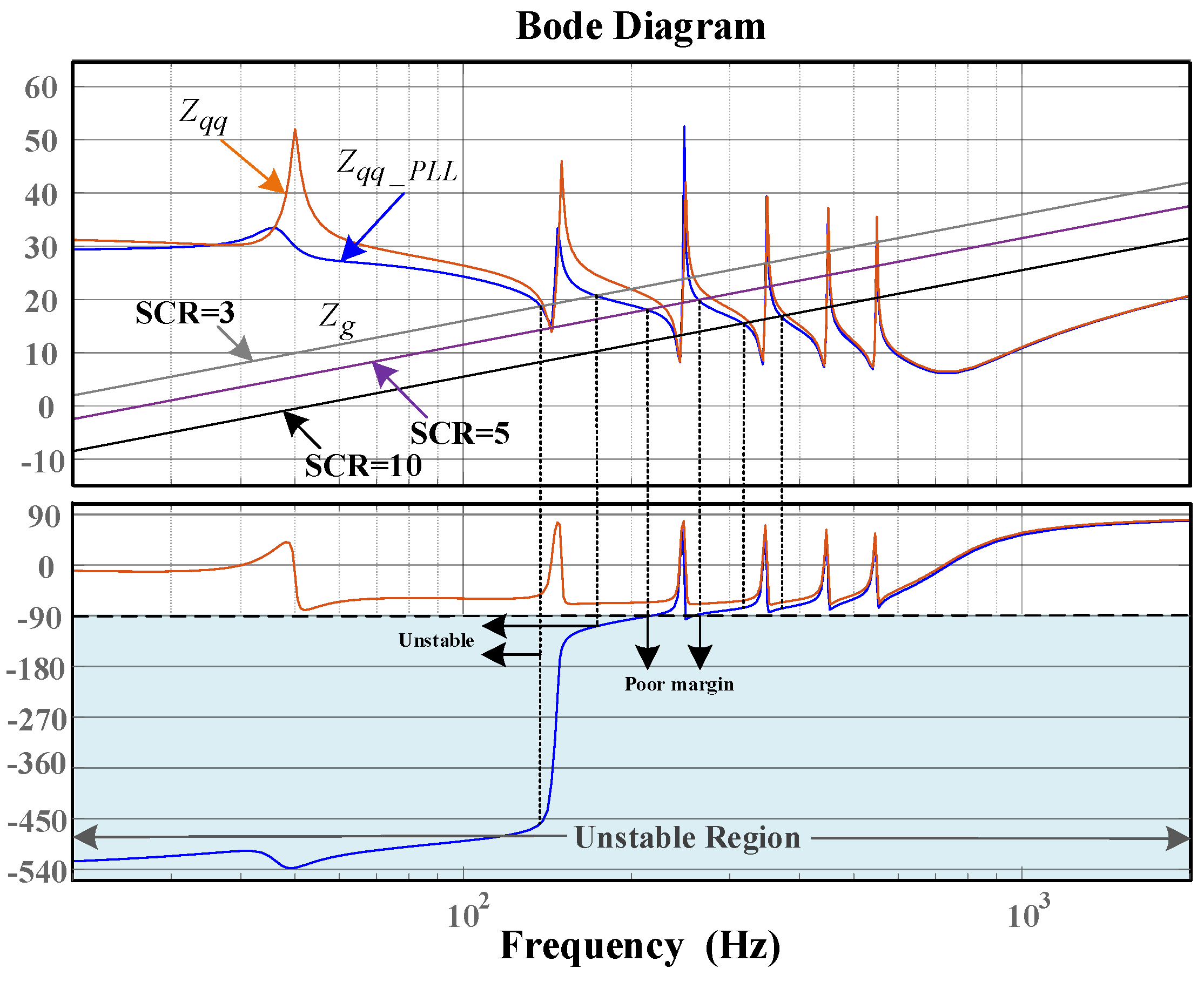
2.2. Stability Analysis of the Inverter Considering the Influence of MFOF-PLL

Analyzing Equation (7), there are two factors associated with the PLL in the denominator of the inverter q-axis output impedance expression Z q q _ P L L , which are H P L L i g q G c ( s ) G X 1 G X 2 and H P L L m q G X 1 G X 2 , respectively. The main reason for this is that only the q-axis voltage at the PCC point is fed back to the reference current and modulation voltage through the loop H PLLig ( s ) and H P L L m ( s ) when considering the effect of MFOF-PLL on the control model of GCI according to Figure 2. As a result, two additional asymmetric negative feedback loops associated with MFOF-PLL are added to the small-signal control block diagram of the inverter, which changes the original output characteristic of the inverter impedance and reduces the adaptability of GCI to the weak grid.
In order to further analyze the influence brought by MFOF-PLL on the inverter stability, the criterion for the stability of the inverter-grid interconnection system is given first. According to the impedance stability theory, the PM of the grid-connected system can be expressed as [30,31]:
P M = 180 + Z i n v ( j 2 π f c ) - Z g ( j 2 π f c )
where, fc denotes the intersection frequency of the magnitude–frequency characteristic curve between inverter impedance Zinv and grid impedance Zg.
To facilitate the analysis, a single-phase GCI with a rated power of 5 kW is used for further illustration. When the short-circuit ratio (SCR) is taken as 3, 5 and 10, respectively, the corresponding grid equivalent inductance Lg is 10 mH, 6 mH and 3 mH, respectively. The bode plot of the inverter impedance, with and without considering MFOF-PLL, can be obtained from Equation (7) as shown in Figure 3, where Zqq_PLL denotes the inverter impedance considering MFOF-PLL and Zqq denotes the inverter impedance without considering MFOF-PLL. The parameter design method of the current controller proposed in [26] is referenced in this paper, which enables the stability margin to be always larger than 20° at the intersection frequency band between inverter and grid impedance, when the influence of MFOF-PLL is ignored.
It can be observed from Figure 3 that the low-frequency characteristic of the inverter impedance changes significantly when the influence of MFOF-PLL is considered. The main reason is that the MFOF-PLL brings an additional term in the denominator of the inverter impedance model, which results in a significant drop in the phase of the inverter output impedance within the bandwidth of MFOF-PLL and deteriorates the robustness of the system. When SCR = 5, the system is in a state of critical stability. Additionally, when the SCR is further decreased, the inverter cannot maintain stable operation. Therefore, the addition of MFOF-PLL in the weak grid significantly increases the risk of inverter oscillation instability.
The above analysis shows that the GCI can always maintain a large PM without considering the effect of MFOF-PLL when the grid impedance Zg changes over a wide frequency band. Therefore, suppressing the function of two asymmetric negative feedback loops H PLLig ( s ) and H P L L m ( s ) brought by MFOF-PLL will help maintain the stability of the inverter-grid interconnected system in the weak grid.

3. Inverter Impedance Reshaping Method Based on APF-PLL

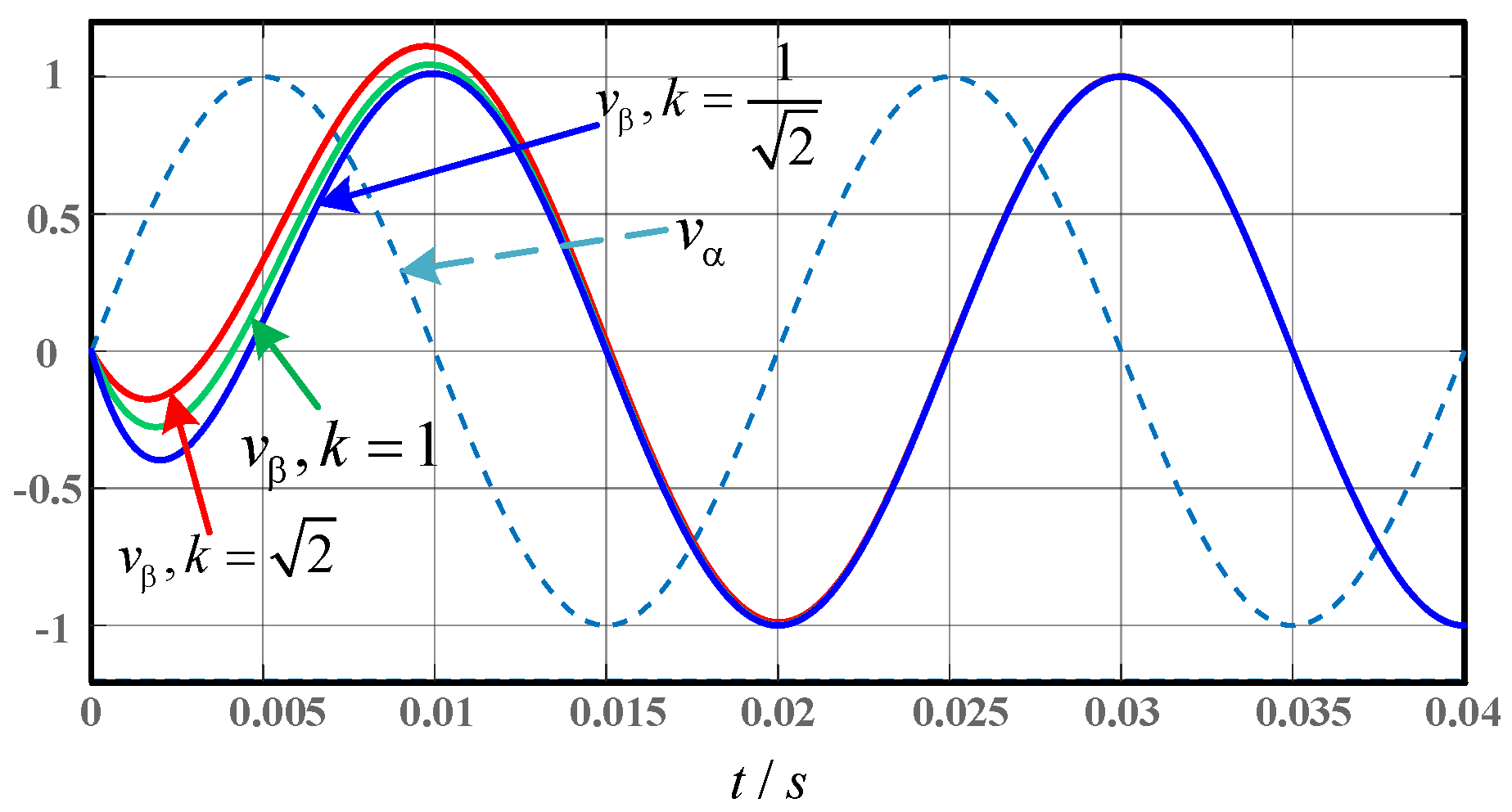
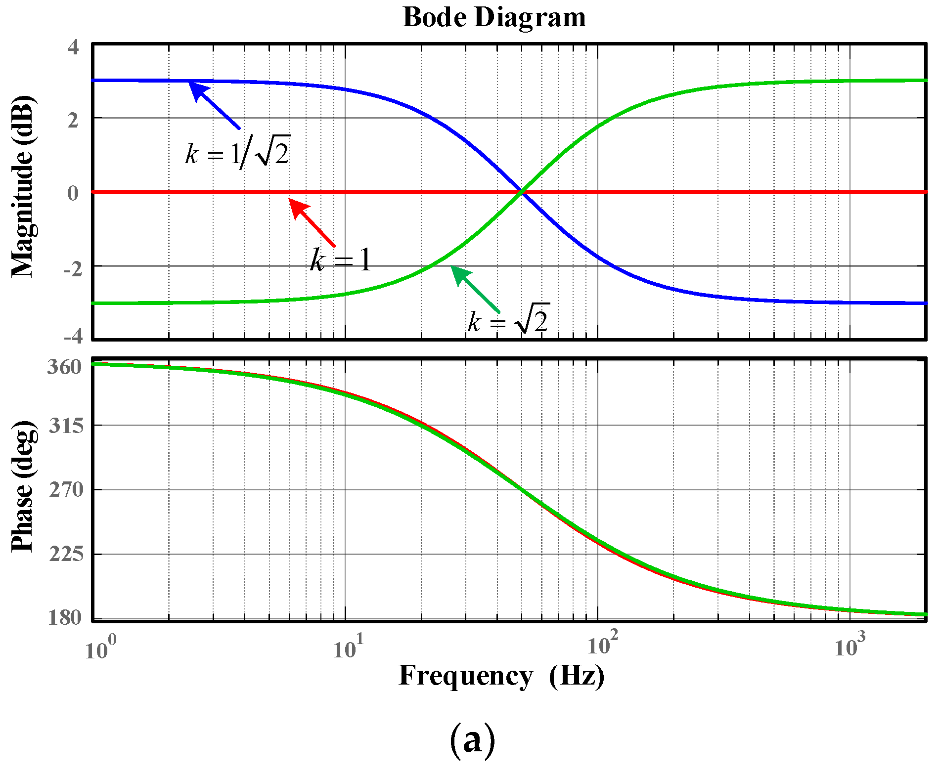
3.1. Improved MFOF-PLL

By combining Equation (7) with the above analysis, it is necessary to reduce the role of the additional term brought by MFOF-PLL on the inverter impedance. Specifically, the impedance reshaping method can be used to make the output characteristic of the additional term brought by MFOF-PLL similar to a negligible or real number term in the low-frequency band. Analyzing Equation (7), all the factors in Z q q _ P L L except H P L L i g q and H P L L m q are determined by the own control system of GCI, which cannot be adjusted arbitrarily. Therefore, to improve the stability margin, the adverse influence brought by MFOF-PLL can only be suppressed by adjusting the output characteristic of the equivalent transfer function related to PLL. To this end, an impedance reshaping method based on improved APF-PLL is proposed in this section.
In [24], the MFOF-PLL is obtained by adding one freedom degree to the APF-PLL as shown in Figure 1b. It is observed that the QSG of MFOF-PLL is a single-input, dual-output control structure. According to Figure 1b, the transfer function can be deduced as:
{ D ( s ) = v α ( s ) v ( s ) = 1 Q ( s ) = v β ( s ) v ( s ) = ω ^ k s k ω ^ + s
where, ω ^ is the output angular frequency of PLL. When the angular frequency of the grid voltage v ( s ) is equal to ω ^ , the output signal of the MFOF-PLL is a pair of quadrature signals with equal amplitude and 90° phase difference. Figure 4 shows the dynamic response curve of Q(s) for different values of k in Equation (9), and it can be observed that the dynamic response of the MFOF-PLL is almost consistent when k changes.
In the weak grid, the intersection frequency of the magnitude–frequency characteristic curve between the inverter impedance and grid impedance is usually in the range of several hundred Hz. In order to suppress the influence of the additional term brought by PLL on the stability of the inverter, the PLL needs to have the ability to adequately attenuate the signal in the range of at least 100–600 Hz. Therefore, a modified first-order filter PLL with complex coefficient filter (CCF-MFOF-PLL) is proposed in this paper as shown in Figure 5. The complex coefficient filter (CCF) shows amplitude attenuation characteristics in the intersection frequency band of magnitude–frequency characteristic curve between the inverter impedance and grid impedance. Therefore, the adverse influence brought by MFOF-PLL can be effectively suppressed by using the CCF as a prefilter link.
Figure 6 shows the control diagram of CCF, whose transfer function can be expressed as:
G CCF = ω c s j ω ^ + ω c
where, ω c is the cut-off angle frequency of CCF.
Analyzing Figure 5, the transfer function of QSG of CCF-MFOF-PLL can be obtained as:
{ D ( s ) = v α ( s ) v ( s ) = ω c s j ω ^ + ω c Q ( s ) = v β ( s ) v ( s ) = ω c ( ω ^ k s ) ( s j ω ^ + ω c ) ( k ω ^ + s )
Selecting the same variation range of the parameter k, bode plot of MFOF-PLL before and after improving is shown in Figure 7. It can be observed from Figure 7a that before the improvement, Q(s) is a high-pass filter when the value of k is large. At this time, it has no rejection capability for the input harmonic component, thus further amplifying the adverse influence brought by PLL on the stability of the inverter. Even if k is small, the amplitude of MFOF-PLL is still larger than −5 dB at the harmonic frequency band, which indicates that the method of adjusting the parameter k still does not effectively suppress the flow of harmonic into MFOF-PLL. Figure 7b shows the bode plot of Q ( s ) . It can be observed that the magnitude–frequency characteristic curve of Q ( s ) at high frequency band is a straight line with a slope larger than −20 dB/dec. In comparison with Figure 7a, the proposed PLL is more adaptable under the harmonic grid. At the same time, the proposed CCF-MFOF-PLL has stronger amplitude attenuation ability in crossover band between the inverter and grid impedance, which can weaken the role of two additional asymmetric negative feedback loops brought by MFOF-PLL and thus suppress the adverse effect of MFOF-PLL on inverter stability.

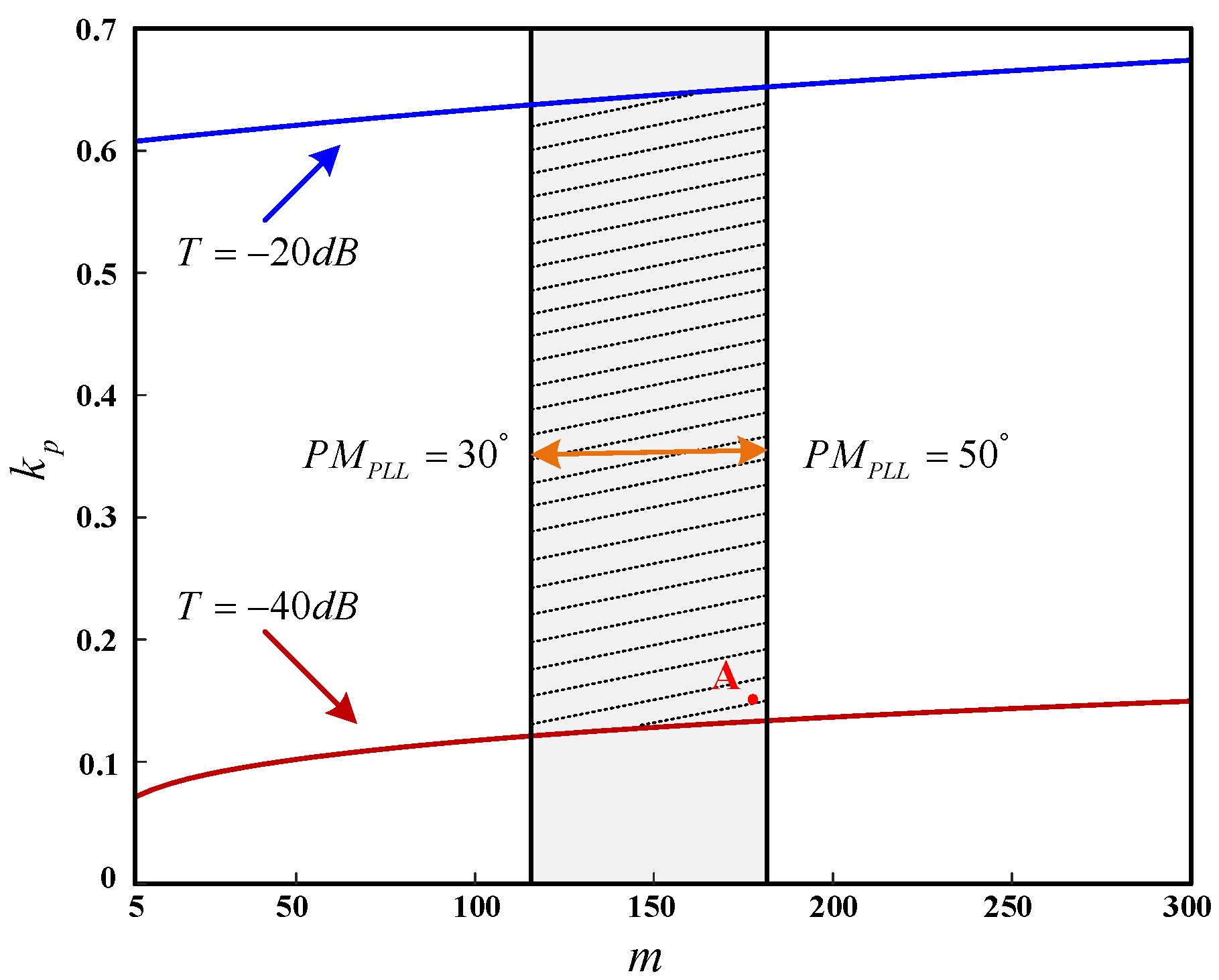
3.2. Parameter Optimization Design Method for CCF-MFOF-PLL

It is worth noting that the parameter of the PI controller in PLL not only directly affects its phase-lock performance, but also determines the stability of the inverter-grid interconnection system. For this purpose, the parameter optimization design method of proposed CCF-MFOF-PLL is given in this section. The small-signal model of CCF-MFOF-PLL can be deduced from Figure 5, which is shown in Figure 8.
Analyzing Figure 8, the open-loop transfer function of CCF-MFOF-PLL can be obtained as:
G o l ( s ) = θ ( s ) Δ θ ( s ) = V n k s + ( k 2 + 1 ) ω 0 2 k s + ( k 2 + 1 ) ω 0 ω c s + ω c ( k p + k i s ) 1 s = V n 0.5 ( s + k 2 + 1 k ω 0 ) s + k 2 + 1 2 k ω 0 ω c s + ω c k p s + k i s 2
To simplify the subsequent analysis, the expression of ω 1 in this paper is defined as:
ω 1 = k 2 + 1 2 k ω 0
Then, Equation (12) can be rewritten as:
G o l ( s ) = θ ( s ) Δ θ ( s ) = V n 0.5 ( s + 2 ω 1 ) s + ω 1 ω c s + ω c k p s + k i s 2
It can be found from references [24,26] that for MFOF-PLL, the value range of k is usually chosen to be [ 1 2 , 2 ] . At this time, the value range of ω 1 is [ 314.16 , 333.22 ] according to Equation (13). In order to lower the order of G o l ( s ) , ω c is chosen to be equal to 2 ω 1 . Then, zero-pole pair elimination can be achieved in (14) and the value range of ω c can be obtained, which is [ 628.32 , 666.44 ] . Then Equation (14) can be simplified as:
G o l ( s ) = V n ω 1 ( k p s + k i ) ( s + ω 1 ) s 2
Figure 9 shows the bode plot of Q ( s ) with the change in ω c , where ω c increases from 628.32 to 666.44. It can be observed that the bode plot of Q ( s ) changes less when ω c is varied within the chosen range. At this time, CCF-MFOF-PLL can maintain strong harmonic rejection capability, which proves the reasonableness of the above simplification.
G o l ( s ) in Equation (15) is a typical second-order system. According to the symmetric optimum method [32], the cut-off angle frequency of the system can be obtained as:
ω c = ω 1 k i k p
Combining Equations (15) and (16), the following Equation (17) can be obtained from the definition of cut-off angle frequency.
| G o l ( j ω c ) | = V n ω 1 k i 2 + ω c 2 k p 2 ω c 2 ω c 2 + ω 1 2 = 1
Solving Equation (17), ω c can be also written as:
ω c = V n k p
Combining Equation (16)–(18), the proportional and integral coefficient of CCF-MFOF-PLL can be obtained as:
{ k p = ω c V n = 1 V n ω 1 k i k p k i = V n 2 k p 3 ω 1 = ω c 2 k p ω 1
It is not difficult to observe from Equation (19) that ki is proportional to kp2. To facilitate the analysis, the constant m is added in this paper. Then the following parameter relationship can be obtained as:
k i = m k p 2
In this paper, two constraints are considered in the process of parameter design. Firstly, the phase margin is considered, which can be obtained from Equation (15) as:
P M P L L = arctan ( ω c k p k i ) arctan ( ω c ω 1 ) = arctan ( V n 2 m 2 2 V n m )
According to Equation (21), the relationship curve between the phase margin of CCF-MFOF-PLL and m is shown in Figure 10. Considering the phase margin of the system from 30 ° to 50 ° , the range of m can be obtained as [113.195,179.556].
Subsequently, considering that the q-axis voltage flowing into PLL contains mainly the 6kth (k = 1, 2, …) harmonic [33], the second parameter constraint is obtained in this paper, which is the perturbation rejection capability of the CCF-MFOF-PLL for the 6th harmonic voltage. From Equation (15), the amplitude of the open-loop magnitude–frequency characteristic curve of PLL at the 6th harmonic frequency can be expressed as:
T = 20 lg | G o l ( j ω a ) | = 20 lg | V n 3 k p 2 m 2 k p 2 + ω a 2 ω a 2 m ω a 2 + k p 2 V n 4 |
where, ω a is the 6th harmonic angle frequency. Considering the value range of T as [−20, −40] dB, the relationship curve between kp and m can be obtained as shown in Figure 11.
According to the above two constraints, the value range of kp is shown in the shade of Figure 11. It is worth noting that the effect of the PLL parameters on the output characteristic of GCI system is also an essential constraint. Therefore, it is necessary to further optimize the PLL parameter design method based on the above analysis.
In order to analyze the effect of m and kp on the inverter, the bode plot of Z qq _ PLL ( s ) with the change in m and kp is shown as Figure 12. It can be observed from Figure 12a that when m changes and kp is constant, the stability domain of the inverter-grid interconnection system is further expanded in low-frequency band with increasing m. Similarly, it can be observed from Figure 12b that when kp changes and m is constant, the phase of Z qq _ PLL ( s ) in low-frequency band increases with decreasing kp and the stability domain of the inverter-grid interconnection system also is expanded. Moreover, comparing Figure 12a,b, the effect of kp on the inverter output characteristic in the weak grid is greater than that of m. In summary, the grid-connected system can maintain a wider stability range with the larger m and smaller kp in the constraint region of Figure 11. Therefore, combining with the above analysis, point A in Figure 11 is chosen. According to Equation (20), ki = 3.94 can be obtained when kp = 0.15 and m = 175 are chosen.

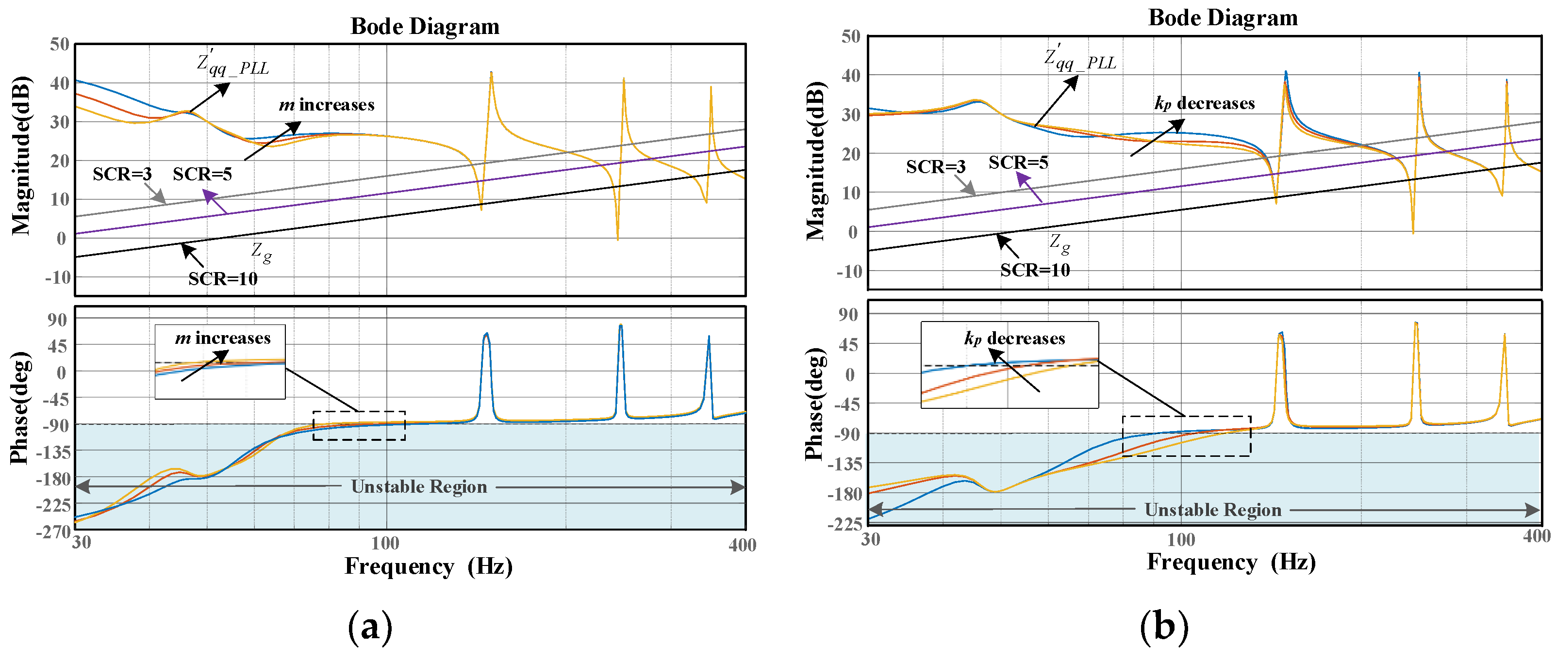
3.3. Stability Analysis of the Inverter after Impedance Reshaping

The inverter impedance can be reshaped by using proposed CCF-MFOF-PLL. At this time, the equivalent transfer function of PLL is modified by multiplying Gccf(s) before the original HPLLig(s) and HPLLm(s). In order to analyze the improvement effect of CCF-MFOF-PLL on the inverter stability, the transfer function from u P C C d q s to i g d q r is discussed as an example. Figure 13 shows the bode plot of the transfer function from u P C C d q s to i g d q r before and after the improvement. It can be observed that due to the addition of CCF, the MFOF-PLL has the stronger amplitude attenuation ability in the frequency band above 100 Hz. At this time, the additional term brought by MFOF-PLL in the inverter impedance denominator can be considered as a negligible factor, which proves that the proposed impedance reshaping method based CCF-MFOF-PLL can suppress the adverse influence brought by MFOF-PLL on inverter stability.
The bode plot of the inverter and grid impedance after impedance reshaping is shown in Figure 14. It can be observed that the instability risk of the inverter is significantly reduced after using CCF-MFOF-PLL in the weak grid. The proposed CCF-MFOF-PLL raises the phase of the inverter impedance in low-frequency band, thus expanding the stability domain of the inverter. It can be observed from Figure 14 that the stable frequency band of the inverter-grid interconnection system is enlarged from f2 > 261 Hz to f1 > 91 Hz. In addition, the inverter has a stability margin of 12° even when SCR = 3 after impedance reshaping. In other words, even if the SCR is dropped to 3 or lower, the inverter can still maintain the strong robustness.
It is not difficult to understand the effectiveness of the proposed impedance reshaping method from the above analysis. On the one hand, the role of two additional asymmetric negative feedback loops brought by MFOF-PLL can be suppressed, and the additional term concerning MFOF-PLL in the inverter impedance can be ignored after using the proposed CCF-MFOF-PLL, which in turn reshapes the inverter output characteristic in low-frequency band and raises the inverter impedance phase. On the other hand, since the CCF has a strong capability of the fundamental component extraction, the method of placing it in MFOF-PLL as a pre-filtering link can significantly improve the extraction capability of it for fundamental frequency signal in grid impedance disturbance state, thus improving the adaptability of the inverter to the grid equivalent inductance in the weak grid.

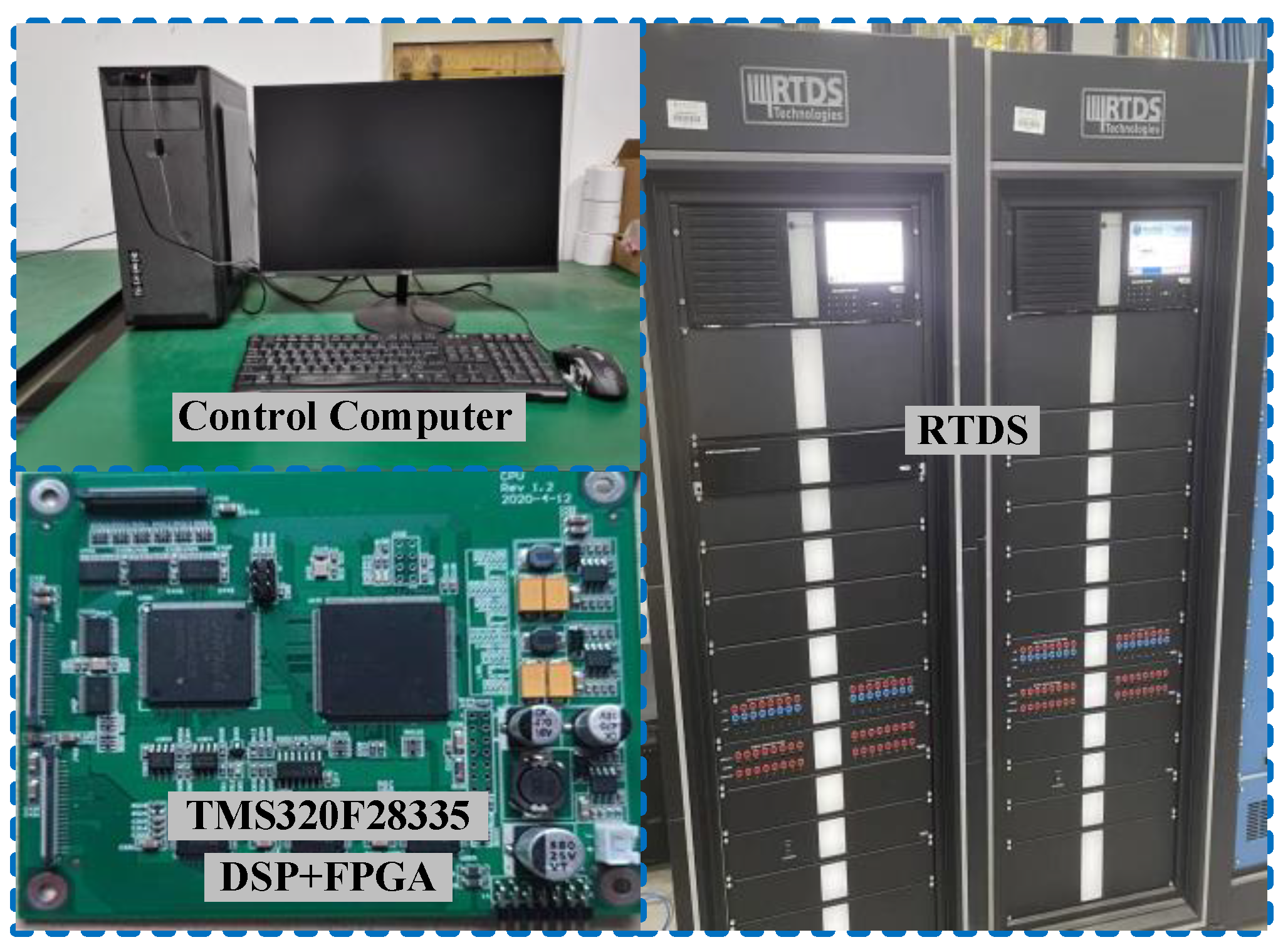
4. Experimental Verification

To further verify the effectiveness of the proposed impedance reshaping method based CCF-MFOF-PLL, the experimental platform of the GCI is built based on a real time digital simulation system (RTDS) as shown in Figure 15. The control link of the inverter is implemented on the TMS320F28335/Spartan6XC6SLX16 DSP + FPGA. The relevant parameters of the of the CCF-MFOF-PLL and GCI are shown in Table 1.
Firstly, to verify the adaptability of the proposed control method in the weak grid, the experimental waveform of the current and voltage at PCC for different SCR (before and after impedance reshaping) are shown in Figure 16 and Figure 17, respectively. When MFOF-PLL is adopted in a strong grid, the inverter can operate stably. However, when the grid equivalent inductance Lg increases to 10 mH, the THD of the current and voltage at PCC is high and the inverter cannot operate stably. On the contrary, when the proposed impedance reshaping method based on CCF-MFOF-PLL is adopted, the inverter can operate stably even when SCR is decreased to 3 and the THD of the inverter output current is 2.32%, which meets the grid-connected power quality standard.
Subsequently, to verify the dynamic performance of the proposed control method, the experimental waveform of the current and voltage at PCC when the reference current changes abruptly is shown in Figure 18. It can be observed that after impedance reshaping, the inverter can operate stably when the reference current is set either from half load to full load, or from full load to half load. At the same time, the inverter can enter the stable state within 0.005 s at the instant of reference current jump, and the dynamic response of the system is fast, thus verifying that the proposed method can effectively solve the problem of system robustness degradation and oscillation instability caused by MFOF-PLL in the weak grid.
In addition, to verify the dynamic characteristics of the proposed impedance reshaping method when the grid parameter changes, the experimental waveform of current and voltage at PCC when SCR changes is shown in Figure 19. It can be observed that the inverter gradually destabilizes when the grid changes from the strong grid to the weak grid before impedance reshaping. When the proposed CCF-MFOF-PLL is used, the inverter can quickly resume stable operation and maintain a fast dynamic response when SCR changes, which verifies that the proposed impedance reshaping method broadens the adaptation range of the inverter to the grid impedance.
Finally, to verify the effectiveness of the proposed control method under the harmonic grid, Figure 20 shows the experimental waveform of current and voltage at PCC after injecting harmonic voltage, in which the 5th and 7th harmonic content of both are 0.1 pu, and Lg is set to 10 mH. It can be observed that when switching the PLL from MFOF-PLL to CCF-MFOF-PLL, the inverter can resume stable operation and the THD of current at PCC is 2.62% at this time, which meets the grid-connected standard. The above analysis indicates that the proposed impedance reshaping method is still highly adaptable even under the harmonic grid.

5. Conclusions

By establishing the small-signal impedance model for GCI, the adverse effect of MFOF-PLL on the stability for the inverter-grid interconnection system in the weak grid is revealed. Then the existing three-phase SRF-PLL structure based on pre-filter is extended to the single-phase APF-PLL application area in this paper, thus obtaining the CCF-MFOF-PLL structure. It can reshape the impedance of the inverter with APF-PLL and improve the stability margin of the grid-connected system, even when the grid equivalent inductance is large according to the impedance stability criterion. Furthermore, a parameter optimization design method for CCF-MFOF-PLL considering the performance of PLL and the stability domain for the inverter is given, which ensures the performance of the PLL under the distorted grid and the stability of inverter-grid interconnection system. The experimental results verify the correctness and effectiveness of the proposed method. It is worth noting that how to obtain the parameter of impedance reshaping method based on APF-PLL by building expressions or quantifying indexes will be the further work to be explored in the future.

Author Contributions

Conceptualization, L.Y. and T.C.; methodology, H.C.; software, X.D.; validation, L.Y., H.C. and S.Z.; formal analysis, X.D.; resources, L.Y.; writing—original draft preparation, T.C.; writing—review and editing, L.Y.; funding acquisition, X.D. All authors have read and agreed to the published version of the manuscript.

Funding

This research was funded by the National Natural Science Foundation of China, grant number 51607179.

Data Availability Statement

The data that support the research of this paper are available on request from the corresponding author upon the reasonable request and with the permission of the China University of Mining and Technology.

Acknowledgments

We would like to express my heartfelt thankfulness for Jiangsu province laboratory of mining electric and automation, which provides the experimental support to our work.

Conflicts of Interest

The authors declare no conflict of interest.

Abbreviations

The following abbreviations are used in this paper:
PLLPhase-locked loop
SRF-PLLSynchronous reference frame phase-locked loop
APF-PLLAll-pass-filter phase-locked loop
CCFComplex coefficient filter
MFOFModified first-order filter
MFOF-PLLModified first-order filter phase-locked loop
CCF-MFOF-PLLModified first-order filter phase-locked loop with complex coefficient filter
GCIGrid-connected inverter
QSGQuadrature signal generator
PMPhase margin
PCCPoint of common coupling
THDTotal harmonic distortion
SCRShort-circuit ratio
RTDSReal time digital simulation system

References

  1. Blaabjerg, F.; Liserre, M.; Ma, K. Power Electronics Converters for Wind Turbine Systems. IEEE Trans. Ind. 2012, 48, 708–719. [Google Scholar] [CrossRef] [Green Version]
  2. Wang, X.; Blaabjerg, F.; Loh, P.C. Grid-Current-Feedback Active Damping for LCL Resonance in Grid-Connected Voltage-Source Converters. IEEE Trans. Power Electron. 2016, 31, 213–223. [Google Scholar] [CrossRef] [Green Version]
  3. Xu, J.; Qian, H.; Hu, Y.; Bian, S.; Xie, S. Overview of SOGI-Based Single-Phase Phase-Locked Loops for Grid Synchronization Under Complex Grid Conditions. IEEE Access. 2021, 9, 39275–39291. [Google Scholar] [CrossRef]
  4. Huang, L.; Wu, C.; Zhou, D.; Blaabjerg, F. A Double-PLLs-Based Impedance Reshaping Method for Extending Stability Range of Grid-Following Inverter Under Weak Grid. IEEE Trans. Power Electron. 2022, 37, 4091–4104. [Google Scholar] [CrossRef]
  5. Feng, G.; Ye, Z.; Xia, Y.; Nian, H.; Huang, L.; Wang, Z. High Frequency Resonance Suppression Strategy of Three-Phase Four-Wire Split Capacitor Inverter Connected to Parallel Compensation Grid. Energies 2022, 15, 1486. [Google Scholar] [CrossRef]
  6. Hamood, M.A.; Marjanovic, O.; Carrasco, J. Adaptive Impedance-Conditioned Phase-Locked Loop for the VSC Converter Connected to Weak Grid. Energies 2021, 14, 6040. [Google Scholar] [CrossRef]
  7. Nian, H.; Liao, Y.; Li, M.; Sun, D.; Xu, Y.; Hu, B. Impedance Modeling and Stability Analysis of Three-Phase Four-Leg Grid-Connected Inverter Considering Zero-Sequence. IEEE Access. 2021, 9, 83676–83687. [Google Scholar] [CrossRef]
  8. Yang, L.; Zhao, L.; Chen, X.; Zhang, Z.; Nian, H.; Zhao, J.; Deng, R.; Yan, L. Robust Active Damping Control for LCL-Type Shunt Active Power Filters. IEEE Access. 2022, 10, 39456–39470. [Google Scholar] [CrossRef]
  9. He, Y.; Wang, X.; Ruan, X.; Pan, D.; Qin, K. Hybrid Active Damping Combining Capacitor Current Feedback and Point of Common Coupling Voltage Feedforward for LCL-Type Grid-Connected Inverter. IEEE Trans. Power Electron. 2021, 36, 2373–2383. [Google Scholar] [CrossRef]
  10. Azghandi, M.A.; Barakati, S.M.; Yazdani, A. Impedance-Based Stability Analysis and Design of a Fractional-Order Active Damper for Grid-Connected Current-Source Inverters. IEEE Trans. Sustain. Energy 2021, 12, 599–611. [Google Scholar] [CrossRef]
  11. Wang, X.; Qin, K.; Ruan, X.; Pan, D.; He, Y.; Liu, F. A Robust Grid-Voltage Feedforward Scheme to Improve Adaptability of Grid-Connected Inverter to Weak Grid Condition. IEEE Trans. Power Electron. 2021, 36, 2384–2395. [Google Scholar] [CrossRef]
  12. Khajeh, K.G.; Farajizadeh, F.; Solatialkaran, D.; Zare, F.; Yaghoobi, J.; Mithulananthan, N. A Full-Feedforward Technique to Mitigate the Grid Distortion Effect on Parallel Grid-Tied Inverters. IEEE Trans. Power Electron. 2022, 37, 8404–8419. [Google Scholar] [CrossRef]
  13. Lin, Z.; Ruan, X.; Wu, L.; Zhang, H.; Li, W. Multi resonant Component-Based Grid-Voltage-Weighted Feedforward Scheme for Grid-Connected Inverter to Suppress the Injected Grid Current Harmonics Under Weak Grid. IEEE Trans. Power Electron. 2020, 35, 9784–9793. [Google Scholar] [CrossRef]
  14. Li, M.; Xiao, H.; Cheng, M. An Adaptive Strategy Based on Repetitive Predictive Control for Improving Adaptability of LCL-Type Grid-Connected Inverters Under Weak Grid. IEEE Trans. Power Electron. 2022, 37, 2562–2572. [Google Scholar] [CrossRef]
  15. Babu, Y.N.; Padhy, N.P. Investigation of Damping Effect of PLL on Low-Frequency Harmonic Stability of Grid-Tied Inverter with αβ and dq Current Control Schemes. IEEE J. Emerg. Sel. Top. Power Electron. 2022, 10, 1046–1060. [Google Scholar] [CrossRef]
  16. Lin, X.; Yu, J.; Yu, R.; Zhang, J.; Yan, Z.; Wen, H. Improving Small-Signal Stability of Grid-Connected Inverter Under Weak Grid by Decoupling Phase-Lock Loop and Grid Impedance. IEEE Trans. Ind. Electron. 2022, 69, 7040–7053. [Google Scholar] [CrossRef]
  17. Xie, Z.; Chen, Y.; Wu, W.; Gong, W.; Guerrero, J.M. Stability Enhancing Voltage Feed-Forward Inverter Control Method to Reduce the Effects of Phase-Locked Loop and Grid Impedance. IEEE J. Emerg. Sel. Top. Power Electron. 2021, 9, 3000–3009. [Google Scholar] [CrossRef]
  18. Zhu, D.; Zhou, S.; Zou, X.; Kang, Y. Improved Design of PLL Controller for LCL-Type Grid-Connected Converter in Weak Grid. IEEE Trans. Power Electron. 2020, 35, 4715–4727. [Google Scholar] [CrossRef]
  19. Li, M.; Zhang, X.; Guo, Z.; Wang, J.; Wang, Y.; Li, F.; Zhao, W. The Control Strategy for the Grid-Connected Inverter Through Impedance Reshaping in q-Axis and its Stability Analysis Under a Weak Grid. IEEE J. Emerg. Sel. Top. Power Electron. 2021, 9, 3229–3242. [Google Scholar] [CrossRef]
  20. Xie, Z.; Chen, Y.; Wu, W.; Gong, W.; Zhou, L.; Zhou, X.; Guerrero, J.M. Admittance Modeling and Stability Analysis of Grid-Connected Inverter with LADRC-PLL. IEEE Trans. Ind. Electron. 2021, 68, 12272–12284. [Google Scholar] [CrossRef]
  21. Zhang, X.; Li, M.; Xu, D. PCC Voltage Perturbation Path Analysis and Compensation for Grid-Connected Voltage-Source Converter Under Weak Grid. IEEE Trans. Ind. Electron. 2021, 68, 12331–12339. [Google Scholar] [CrossRef]
  22. Berg, M.; Aapro, A.; Luhtala, R.; Messo, T. Small-Signal Analysis of Photovoltaic Inverter with Impedance-Compensated Phase-Locked Loop in Weak Grid. IEEE Trans. Energy Convers. 2020, 35, 347–355. [Google Scholar] [CrossRef]
  23. Lin, X.; Wen, Y.; Yu, R.; Yu, J.; Wen, H. Improved Weak Grids Synchronization Unit for Passivity Enhancement of Grid-Connected Inverter. IEEE J. Emerg. Sel. Top. Power Electron. 2022, 1. [Google Scholar] [CrossRef]
  24. Golestan, S.; Guerrero, J.M.; Vasquez, J.C.; Abusorrah, A.M.; Al-Turki, Y. All-Pass-Filter-Based PLL Systems: Linear Modeling, Analysis, and Comparative Evaluation. IEEE Trans. Power Electron. 2020, 35, 3558–3572. [Google Scholar] [CrossRef]
  25. Stojic, D.; Georgijevic, N.; Rivera, M.; Milic, S. Novel Orthogonal Signal Generator for Single Phase PLL Applications. IET Power Electron. 2018, 11, 427–433. [Google Scholar] [CrossRef]
  26. Xia, T.; Zhang, X.; Tan, G.; Liu, Y. All-Pass-Filter-Based PLL for Single-Phase Grid-Connected Converters Under Distorted Grid Conditions. IEEE Access 2020, 8, 106226–106233. [Google Scholar] [CrossRef]
  27. Qian, Q.; Xie, S.; Huang, L.; Xu, J.; Zhang, Z.; Zhang, B. Harmonic Suppression and Stability Enhancement for Parallel Multiple Grid-Connected Inverters Based on Passive Inverter Output Impedance. IEEE Trans. Ind. Electron. 2017, 64, 7587–7598. [Google Scholar] [CrossRef]
  28. Wen, B.; Boroyevich, D.; Burgos, R.; Mattavelli, P.; Shen, Z. Analysis of D-Q Small-Signal Impedance of Grid-Tied Inverters. IEEE Trans. Power Electron. 2016, 31, 675–687. [Google Scholar] [CrossRef]
  29. Wen, B.; Dong, D.; Boroyevich, D.; Burgos, R.; Mattavelli, P.; Shen, Z. Impedance-Based Analysis of Grid-Synchronization Stability for Three-Phase Paralleled Converters. IEEE Trans. Power Electron. 2016, 31, 26–38. [Google Scholar] [CrossRef]
  30. Wang, X.; Harnefors, L.; Blaabjerg, F. Unified Impedance Model of Grid-Connected Voltage-Source Converters. IEEE Trans. Power Electron. 2018, 33, 1775–1787. [Google Scholar] [CrossRef]
  31. Sun, J. Impedance-Based Stability Criterion for Grid-Connected Inverters. IEEE Trans. Power Electron. 2011, 26, 3075–3078. [Google Scholar] [CrossRef]
  32. Golestan, S.; Guerrero, J.M.; Vasquez, J.C. Three-Phase PLLs: A Review of Recent Advances. IEEE Trans. Power Electron. 2017, 32, 1894–1907. [Google Scholar] [CrossRef] [Green Version]
  33. Hui, N.; Wang, D.; Li, Y. A Novel Hybrid Filter-Based PLL to Eliminate Effect of Input Harmonics and DC Offset. IEEE Access. 2018, 6, 19762–19773. [Google Scholar] [CrossRef]
Figure 1. Structure and model of single-phase grid-connected inverter: (a) the control block diagram of the single-phase LCL-type grid-connected inverter; (b) the control diagram of MFOF-PLL.
Energies 15 07355 g001
Figure 2. The small-signal control block diagram of the inverter considering the influence of MFOF-PLL.
Energies 15 07355 g002
Figure 3. Bode plot of the inverter impedance with and without considering MFOF-PLL.
Energies 15 07355 g003
Figure 4. Dynamic response curve of Q(s).
Energies 15 07355 g004
Figure 5. Control block diagram of CCF-MFOF-PLL.
Energies 15 07355 g005
Figure 6. Control diagram of CCF.
Energies 15 07355 g006
Figure 7. Bode plot of MFOF before and after improving: (a) bode plot of Q ( s ) ; (b) bode plot of Q ( s ) .
Energies 15 07355 g007aEnergies 15 07355 g007b
Figure 8. Small-signal model of CCF-MFOF-PLL.
Energies 15 07355 g008
Figure 9. Bode plot of Q ( s ) with the change in ω c .
Energies 15 07355 g009
Figure 10. Relationship curve between phase margin of CCF-MFOF-PLL and m.
Energies 15 07355 g010
Figure 11. Relationship curve between kp and m.
Energies 15 07355 g011
Figure 12. Bode plot of Z qq _ P L L ( s ) with the change in m and kp: (a) m changes, kp is constant; (b) kp changes, m is constant.
Energies 15 07355 g012
Figure 13. Bode plot of the transfer function from u P C C d q s to i g d q r .
Energies 15 07355 g013
Figure 14. Bode plot of inverter and grid impedance after impedance reshaping.
Energies 15 07355 g014
Figure 15. Experimental platform of the GCI.
Energies 15 07355 g015
Figure 16. Experimental waveform of current and voltage at PCC for different SCR before impedance reshaping: (a) Lg = 0 (SCR > 10); (b) Lg = 10 mH (SCR = 3).
Energies 15 07355 g016
Figure 17. Experimental waveform of current and voltage at PCC for different SCR after impedance reshaping: (a) Lg = 0 (SCR > 10); (b) Lg = 10 mH (SCR = 3).
Energies 15 07355 g017
Figure 18. Experimental waveform of current and voltage at PCC when the reference current changes abruptly: (a) from half load to full load; (b) from full load to half load.
Energies 15 07355 g018
Figure 19. Experimental waveform of current and voltage at PCC when SCR changes: (a) with MFOF-PLL; (b) with CCF-MFOF-PLL.
Energies 15 07355 g019
Figure 20. Experimental waveform of current and voltage at PCC after injecting harmonic voltage.
Energies 15 07355 g020
Table 1. Relevant parameters of the CCF-MFOF-PLL and GCI.
SymbolParameterValue
PoRated power5 kW
f1Fundamental frequency50 Hz
CFilter capacitors10 μF
kpProportion coefficient of CCF-MFOF-PLL0.15
kiIntegral coefficient of CCF-MFOF-PLL3.94
kcpProportion coefficient of current regulator10
kcrResonance coefficient of current regulator600
fswSwitching frequency15 kHz
fsSampling frequency15 kHz
Hi1Active damping factor10
L1Inverter-side inductance1 mH
L2Grid-side inductance1 mH
Publisher’s Note: MDPI stays neutral with regard to jurisdictional claims in published maps and institutional affiliations.

