Review

Available Technologies and Commercial Devices to Harvest Energy by Human Trampling in Smart Flooring Systems: A Review

1
Department of Innovation Engineering, University of Salento, 73100 Lecce, Italy
2
Facultad de Ingeniería, Universidad Panamericana, Aguascalientes 20290, Mexico
*
Author to whom correspondence should be addressed.
Energies 2022, 15(2), 432; https://doi.org/10.3390/en15020432
Submission received: 16 November 2021 / Revised: 6 December 2021 / Accepted: 29 December 2021 / Published: 7 January 2022

Abstract

:
Technological innovation has increased the global demand for electrical power and energy. Accordingly, energy harvesting has become a research area of primary interest for the scientific community and companies because it constitutes a sustainable way to collect energy from various sources. In particular, kinetic energy generated from human walking or vehicle movements on smart energy floors represents a promising research topic. This paper aims to analyze the state-of-art of smart energy harvesting floors to determine the best solution to feed a lighting system and charging columns. In particular, the fundamentals of the main harvesting mechanisms applicable in this field (i.e., piezoelectric, electromagnetic, triboelectric, and relative hybrids) are discussed. Moreover, an overview of scientific works related to energy harvesting floors is presented, focusing on the architectures of the developed tiles, the transduction mechanism, and the output performances. Finally, a survey of the commercial energy harvesting floors proposed by companies and startups is reported. From the carried-out analysis, we concluded that the piezoelectric transduction mechanism represents the optimal solution for designing smart energy floors, given their compactness, high efficiency, and absence of moving parts.

1. Introduction

Energy harvesting is a research area of great interest for the scientific community and the R&D departments. It constitutes a simple and sustainable way to collect energy from various sources available in the environment (i.e., light, heat, wind, salinity gradients, and kinetic energy deriving from human walking or vehicle movements) [1,2,3,4,5]. The primary goal is to reduce the emission of tons of CO2. Harvesting involves capturing energy from different environmental and anthropic sources and converting it into electric energy that can be used to supply wearable technology, sensor networks, or stored for large-scale power production [6,7,8,9,10]. Specifically, the kinetic energy related to the human and vehicle motions represents a valuable energy source that is commonly wasted, despite being used to generate electric energy.
In this context, researchers and companies have proposed several smart harvesting floors in the literature to scavenge a reasonable amount of energy to feed lighting and screens into public spaces or buildings. This review paper aims to analyze the state-of-art of smart energy harvesting floors for determining the best solution to feed the applications that require a power output in the range from 3 W to 7 W, such as lighting systems and charging columns. This work also discusses the rectifiers and signal regulation systems, which could increase the collected energy. In the paper, some harvesting prototypes that researchers have created to enhance the efficiency of the existing commercial systems are analyzed. These prototypes involve knowledge in different fields, such as nanomaterials, electronics, mechanics, applied physics. Some solutions are more suitable for small-scale power production or are not useful for harvesting energy from human walking. However, the ideas under these technologies can be extended to hybridise a large-scale device.
Similar review works are presented in the scientific literature, dealing with the different technologies for scavenging energy from pavements. In [11], the authors investigated and compared different technologies and solutions for harvesting energy from walking. Specifically, the main transduction mechanisms identified for kinetic energy harvesting are piezoelectric, electromagnetic, electrostatic, and magnetoelectric materials. the paper describes several harvesting solutions, both those placed on the human body and those installed inside tiles. They concluded that the smart harvesting floors are a more efficient and reliable strategy for scavenging walking energy, regardless of body conditions. Moreover, S. Ahmad et al. completed a comprehensive survey on pavements and roadways for energy harvesting applications; in particular, the paper discusses several energy harvesting methods, materials, commercial systems, and future challenges [12]. The researchers identified open challenges and study margins to improve the efficiency and reliability of energy harvesting floors, enabling their wide employment of these technologies in smart city scenarios.
Similarly, in [13], D. Vizzari et al. investigated the main energy harvesting technologies applicable to smart pavements, highlighting strengths and weaknesses, providing useful insights for future optimization. Notably, they focused on thermal and photovoltaic harvesting methods applied to pavements or roadways, using solar cells or thermal-solar systems covered by a semi-transparent protective layer. Furthermore, they described energy harvesting floors based on a piezoelectric mechanism for scavenging walking energy. Furthermore, in [14], the authors analysed the main key issues in energy harvesting floors, determining the best transduction mechanism for Malaysian operative conditions. In particular, they investigated both photovoltaic, thermoelectric, geothermic, and piezoelectric harvesting technologies, comparing them from the point of view of efficiency, cost and side effects. Lastly, they concluded that the geothermal harvesting mechanism is the best solution for the Malaysian environmental conditions; however, they identified the piezoelectric mechanism as the most promising solution for the next generation of harvesting floors. Comparisons between our review work with respect to other similar surveys above discussed are reported in Section 4.
This review paper is arranged as follows. Section 2 discusses, at first, the fundamentals of the main harvesting mechanisms applicable in this field (i.e., piezoelectric, electromagnetic, triboelectric, and relative hybrids). Their application’s physical concepts and limits are described, and materials and useful devices for designing innovative smart tiles are proposed. Moreover, the power management strategies are discussed, fundamental for improving the harvesting efficiency. Later, an overview of scientific works related to energy harvesting floors is presented, focusing on the architectures of the developed tiles, the transduction mechanism, and the output performances.
Section 3 reports a survey of companies and startups’ commercial energy harvesting floors, pointing out their structure, transduction mechanisms, and output performances. However, not all these models are made up of ecological material, and not all these smart floors are now available on the market. Some solutions provide a data transmission system that enriches the user experience when walking on the tile. Lastly, Section 4 reports a brief discussion of all the reviewed technologies and highlights the most promising among them.

2. Smart Tiles for Energy Harvesting Applications: Current Technologies and Future Challenges

Energy Harvesting is a process that allows the production of useful electric energy through an appropriate system of transduction (e.g., piezoelectric, electromagnetic, electrostatic or triboelectric, etc.), conversion, regulation and storage from different energy sources available in the environment. This idea allows clean and sustainable energy production in a world where 85% of energy needs depend on fossil fuels.
Despite the 2020 turmoil caused by the COVID-19 pandemic, the global energy demand is enormously increased. Notably, there has been a heavy exploitation of renewable sources (wind and solar power production), with an impressive increase of 238 GW in last year—50% more than any previous increase. Equally impressive was the decrease in carbon emissions, with emissions falling by more than 6% in 2020, the largest decline since 1945. The rate of decline in carbon emissions is in line with that of the world’s needs every year for the next 30 years to be on track to meet the Paris Agreement goals. In addition, oil demand is estimated to have decreased by 9.3% [15]. An example of technology in line with this goal are smart surfaces, i.e., tiles that produce electricity from the pressure applied by the people who step on them. The core of this technology is the harvester, which can exploit different transduction mechanisms, such as piezoelectric, triboelectric, electromagnetic, electronic conditioning systems, and the material constituting the tile.
This paragraph provides an overview of the physical principle of operation, problems, and current developments in this field, focusing on piezoelectric, triboelectric and electromagnetic harvesters.

2.1. Transduction Mechanisms, Conditioning Sections, Operational Strategies Applied to Smart Floor Applications

Electrical energy can be scavenged by footsteps in three convenient ways: from the direct piezoelectric effect, electrostatic energy produced by the contact of two different triboelectric layers, and electromagnetic effect, or using mechanical solutions to convert the linear movement to rotate for the electromagnetic generator.

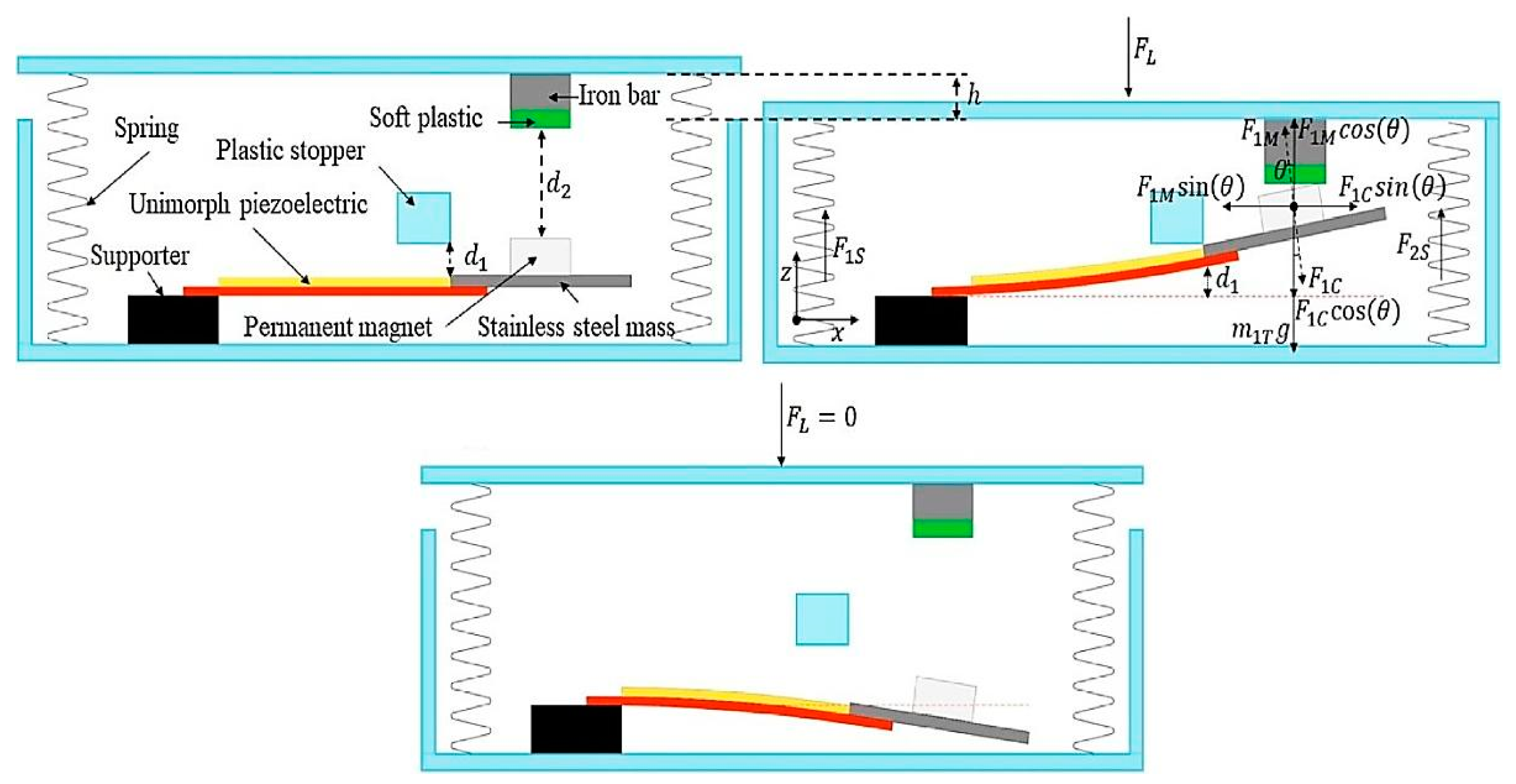
2.1.1. Piezoelectric-Based Smart Floor Solutions: Working Principle and Theoretical Fundamentals

A common approach to designing a piezoelectric-harvesting structure, called piezoelectric device flooring layers, is shown in Figure 1 [16,17]. The tile comprised a floating surface suspended by springs above the piezoelectric elements; the tile travels downwards when pressure is applied to its surface. The projections on the tile surface come into touch with the piezoelectric substance. There is enough space between the springs’ surface and the tile for free deflection. The imparted force creates strains inside the piezoelectric material, which generate electric charges. The spring ensures that the piezo material remains stable and is not damaged by the extra load. The base plate is securely fitted into the frame to support the piezo material during compression [18].
The piezoelectricity represents the generation of electric charge in solid material (such as crystals, ceramics, DNA, or some proteins) from a pressure variation on the sensor. It is a reversible process in crystal materials with an asymmetric electric balance center: the electric charge is generated after applying pressure on the material (direct piezoelectric effect). Conversely, an extension or contraction of the material can be obtained by applying an electric field (reverse piezoelectric effect).
The piezoelectric phenomenon depends on the chemical structure of the solid. The polarization vector (and the directly proportional charge density) changes with the applied mechanical stress because it causes the charge separation in the individual atoms: they get pushed around, and suddenly the crystal can conduct an electrical current (Figure 2) [19]. Polycrystalline ceramic, the piezoelectric material with the highest activity, comprises small crystallites randomly oriented. These last are constituted by small “domains”, or regions featured by similar dipole configurations; the global effect of polar domains oriented randomly is a lack of piezoelectricity at first. However, macroscopic polarization is conferred to the material by a poling process. Examples of piezoelectric materials are natural quartz crystals, polycrystalline piezo-ceramics, semi-crystalline polyvinylidene polymer, bone, and wood.
The single crystals PZN-PT (lead zirconate titanate) and PMN-PT (lead magnesium niobate-lead titanate) have the best piezoelectric characteristics but are more temperature-sensitive, fatigue sensitive, and difficult to manufacture. As a result, PZT continues to be the most widely used piezoelectric material in energy harvesters [20]. Another useful material is the polycrystalline barium titanate (BaTiO3), with a positive temperature coefficient of resistance, which makes it applicable for thermistors and self-regulating electric heating systems. PZT (Lead Zirconate Titanate) transducers like a cymbal, conical, and PMUT (Piezoelectric Micromachined Ultrasonic Transducers) are suitable for high-frequency operation. On the contrary, harvesters realised with piezopolymers (PVDF- polyvinylidene fluoride, P(VDF-TrFE)) featured by semi-cylindrical shape can be employed for applications with a low-frequency [21]. The most employed piezo materials are PZT, PVDF, ZnO (Zinc Oxide), and AlN (Aluminium Nitride), etc. [22]. The cymbal and bridge are the most common designs for piezoelectric harvesters [23]. Ceramic piezoelectric transducers are relatively fragile; in fact, they can be destroyed when exposed to energy produced from human motions [24,25]. Nowadays, there are different structures of piezoelectric generators; in particular, they are classified into two categories:
  • Single-Layer Piezoelectric Generators: they consist of a piezoelectric foil and a passive substrate;
  • Multi-Layer Piezoelectric Generators: they are constituted by a series of piezoelectric ceramic foils stacked on each other and enclosed between two electrodes (Figure 3). There is only one electrode between two adjacent foils to optimise the dimensions and number of components, realizing a stack of thin piezoelectric layers (i.e., <1 mm thickness) interposed between electrodes. The electric fields (and consequently the potential difference) generated by the single piezoelectric layer, perpendicular to the foils, change towards each layer. A multi-layer piezo generator provides a lower output voltage than that provided by a single-layer piezo harvester. Conversely, a multi-layer generator provides an output current significantly higher than a single-layer piezoelectric generator [26].
The multi-layer structures are a common solution for enhancing the output power of piezoelectric energy harvesters than a single-layer generator with the same thickness. Furthermore, multi-layer generators are featured by lower polarization voltage avoiding the breakdown risk during the polarization step; also, they show a lower output impedance than a single layer harvester, making the power extraction more simple [27] (Table 1). However, the single-layer piezoelectric generators are commonly featured by a higher output voltage than multi-layer ones, since the stacked structure increases the inner capacitance [28]. The multi-layer structure can be connected in series or parallel, resulting in different device capacitances, output impedance, and charge distribution inside the generator [29]. Table 1 reports a comparison between single-layer and multi-layer generators, highlighting their advantages and disadvantages.
Knowing how quickly a piezoelectric transducer can respond to an input solicitation is useful information; the fundamental resonant frequency (Fr) represents the main parameter contributing to this response. Up to its resonance frequency, a sinusoidal input can be followed by a piezo element; this last is unable to keep up with stimulation beyond this point due to inertia. The mechanical response time, tr, is the time taken by a piezoelectric element to bring the amplitude of the oscillation from zero to its maximum positive amplitude at the resonant frequency. This parameter is 1/4 the time the transducer takes to perform a full bipolar cycle. Due to hysteresis and other losses, tr is rarely obtained. The following formula is more realistic than the previous estimation:
t r ~ 1 3 F r
A piezoelectric transducer working under its fundamental resonance frequency can be viewed as a capacitive element responsible for supplying, withdrawing, and storing charges. However, the generated charge could be lost through the piezo-material, bulk, or external conditioning section. The equivalent scheme is represented in Figure 4. In the resonance condition, the transducer can be modelled as a capacitor with a parallel resistor (with a value equal to its capacitance), modelling the environment or internal loss within the transducer.
When the piezoelectric transducer works near the resonant frequency, its impedance is:
Z = [ R 1 + j ( ω L 1 1 ω C 1 ) ] 1 j ω C 0 R 1 + j ( ω L 1 1 ω C 1 ) + 1 j ω C 0
where C 0 is the static clamping capacitor of the piezoelectric transducer, C 1 the dynamic capacitor, L 1 the dynamic inductance, and R 1 the dynamic equivalent resistance, ascribable to internal loss and external load. This formula shows that piezoelectric generator impedance depends on frequency, changing when the resonant state varies. The resistance component R 1 is usually the impedance’s real part, whereas the impedance’s imaginary part is termed the anti-component X, and the series impedance is X 1 . When the imaginary part of X 1 is 0, the series resonant angular frequency is (1/ C 1 L 1 )1/2. The minimum impedance frequency f m is defined when the impedance Z is the lowest, whereas the maximum impedance frequency f n is defined when the impedance Z is the highest. Instead, the parallel resonant frequency f p is reached when resistance R is maximum, whereas the resonant frequency f r and the anti-resonance frequency f a are obtained when the anti-component X 1 is 0 (Figure 5) [30]. At the resonance frequency, reactance cancellation of the dynamic inductance and capacitance occurs. Application condition of the best impedance matching is obtained for a transducer in a resonant state, where it behaves as a purely resistive load. For quasi-static piezoelectric elements, 2/3 of the fundamental resonance frequency signs the limit of the useful frequency band; for resonant applications, the operating frequency range is restricted to a narrow band around the used resonant modes.
Open-circuit voltage and short-circuit charges are commonly used to characterise piezoelectric generators. The overall charge created at the greatest suggested applied stress, when the charge can move from one electrode to the other, and no output voltage is required, it is called a short-circuit charge or Q s . The voltage created in correspondence to the maximum suggested stress level with no charge moving from one electrode to the other is defined as an open-circuit voltage or V o . When the voltage is zero, the charge is highest; when charge transfer is zero, the voltage is maximum.
Generally, a piezo transducer produces a specified amount of charge and produces a voltage, determining its operating point (OP) on the voltage vs. charge graph. The optimal OP is obtained when the moved charge corresponds to one-half the open-circuit voltage; this condition is verified when the generated charge equals one-half of the short-circuit charge [31].
The electromechanical coupling coefficient k expresses the transducer’s capability to convert mechanical to electrical energy or vice-versa. The ratio of electrical energy output to mechanical energy input is equal to the square of the coupling coefficient. In a real bending transducer, a fraction of its mechanical energy is stored in the mount and metal support layer; thus, it is fundamental to maximise the output work of the piezoceramic material compared to bending layers. The relative dielectric constant K is defined as the ratio of piezoceramic material’s permittivity to that of empty space, ε 0 ; K value establishes the sample capacitance according to the following equation [32]:
C = K   ϵ A T
where A is the electrode surface, and T is the thickness of the ceramic layer or layers between electrodes. As detailed above, high inner capacitance values are not desirable for all harvesting applications, since they involve low output power from the piezoelectric generators. The piezoelectric voltage coefficients g i j , elements of a 3 × 6 matrix G, correlating the produced electric field E (with open-circuited electrodes) with applied stress T. The coefficients g i j are expressed in units of V/m per N/m2 [33].
E i = g i j T j    
The piezoelectric charge coefficient d i j is defined as a third-order tensor, representable as a 3 × 6 matrix, correlating the charge moved for unit area (with short-circuited electrodes), expressed in C/m2, with the applied stress T. The coefficients d i j are expressed in C/N [33].
D i = d i j T j
Moreover, Young’s modulus Y is defined as the stress required to generate a unit strain, describing the material stiffness in units of N/m2. Since mechanical stress applied on a piezoceramic element produces an electrical response opposing the corresponding strain, the effective Young’s modulus with short-circuited electrodes is lower than that with the open-circuited electrodes [31].
However, for the considered application, the piezoelectric generator must operate with low (Hz-range) and random frequency solicitations derived from human movements; this means that the applied frequency does not match with the piezoelectric generator’s resonant frequency, resulting in reduced conversion efficiencies. As detailed in Section 2.2, several frequency up-conversion techniques that stimulate a harvester from low-frequency input vibration have recently been investigated to attain a high harvesting efficiency. These solutions make the oscillation frequency always tuned to the resonant frequency regardless of the vibration source. A commonly used solution is to initially deflect the piezoelectric cantilever or disk, leaving it oscillating. Mechanical contact or non-contact magnetic interaction can be implemented to provide an initial deflection. This strategy is applied to convert a low-frequency vibration resulting from pedestrian steps into usable electrical energy [34,35].

2.1.2. Electromagnetic-Based Smart Floor and Power Management Solutions: Working Principle and Theoretical Fundamentals

Most of the energy produced by piezoelectric generators is localised around their natural frequency, greater than 200 Hz, but the human motion has a bandwidth from 1 to 10 Hz. On the other hand, the electromagnetic generators work near this frequency range; as a result, they are better suited to gather energy from human movement. Furthermore, electromagnetic generators have a higher power density and a lower cost than piezoelectric generators. For energy harvesting floors, the main limitations regard the size and depth of the device, given the reduced available space, whereas there is not any limitation related to weight. An electromagnetic harvester scheme can employ different electromagnetic sources, such as electromagnetic generators or magnet-coil systems [36]. The dynamo is an example of an electromagnetic generator; it is a commutator-based electrical generator that generates a direct current (DC). Considering the limitations of the dimensions and displacement involved in energy harvesting tiles (15 ÷ 20 mm), small 12 V or 24 V DC motors are employed. The synchronous generator can be used for harvesting applications, where the rotation speed is synchronised with the electrical frequency [37]. The brushless DC generator has no brushes or commutators and are therefore safer and more reliable than standard brushed DC generators because no brushes are rubbing against anything, and so no energy is lost due to friction.
Another way to produce electromagnetic energy is by working directly on induction law or Faraday’s law. This last states that the electromotive force induced into a close circuit equals the negative derivative with respect to the time of the magnetic flux concatenated by the circuit. This means that energy can be scavenged by moving a magnet in a copper coil [38].
E = N ϕ B t
E is the electromotive force, ϕ B the magnetic flux, and N the number of coils. Moreover, Lenz’s law defines the direction of induced electromotive force. If the magnet is moving in the coils, the induced voltage is [38]:
E = B l v
where v is the magnet’s translation speed, l is the coil length, and B is the magnetic induction of the magnet. The efficiency of energy generation is heavily affected by the transmission efficiency, as well as that of the generator. However, size restrictions to the gearing system inhibit the generation efficiency, since mechanical and electrical loss increase. In the literature, microscale magnetic generators have demonstrated efficiencies from 10% to 70% for milliwatt power generations.
Then, the power management section and storage device convert and store the electrical energy from AC-generated signals (Figure 6). The rectifier converts the AC voltage to DC; these last are classified as passive or active depending on the devices employed and whether or not an external DC power supply is required. In passive rectification, passive filtering devices and diodes are commonly employed. In contrast, the active rectifiers commonly utilise MOSFETs and BJTs as switches, and active drive or control circuits must control them. As a result, a DC power supply, normally external, is required to power the active components. Besides, the rectifiers can be single half-wave or double half-wave rectifiers. Adopting four diodes arranged in the well-known Graetz bridge configuration allows us to obtain a signal that combines a positive half-wave and the inverted negative half-wave (double half-wave).
This solution, widely used in power supplies, makes the subsequent filtering and levelling of the voltage much easier until a DC voltage is obtained, without requiring a transformer with double winding and a central tap. The main disadvantage of this method is the voltage drop equal to that of two diodes in series, which is about 1.4 volts. When very small voltages are considered, the excessive loss and distortion could be intolerable [39]. Conventional passive full-wave bridge rectification has four junction-based diodes (p/n or Schottky). To eliminate forward voltage drop across the diodes and power loss in the diode-based full-wave rectifiers, two P-type and two N-type MOSFETs can be used, in particular inside integrated circuits fabricated with CMOS technology. Active or synchronous rectifiers increase the conversion efficiency by decreasing the voltage drop in circuit elements and power losses in switches. Nevertheless, active components involve a supplementary power consumption on the rectifier. Active components are a disadvantage in energy harvesters’ power conditioning circuits, since their output power is limited. Therefore, passive MOSFET rectifiers represent the optimal solution for rectifying the signals generated by electromagnetic harvesters (Figure 7) [40].
The buck-boost converter transduces the time-varying DC voltage in output from the rectifier into DC power suitable for battery recharging. In addition, they must operate following a matching-impedance circuit for ensuring the maximum power transfer from harvester to conditioning section. Essentially, a boost converter does the opposite of a buck converter or a step-down converter, which reduces—rather than raises—the DC voltage. The buck-boost converters include both types, making them suitable for every DC source. In particular, buck and boost converters can be combined in the 4-switch converter. It has two modes of operation: buck (step-down) and boost (step-up). A two-switch buck-boost converter can be created using two diodes; however, upgrading the diodes to FET transistor switches is relatively inexpensive, and the efficiency improves due to the reduced voltage drop [41]. The double-switch buck-boost converter based on diode rectification is defined as non-synchronous; however, MOSFET replaces the diode in a synchronous conversion scheme [42]. The four-switch buck-boost converter is featured by synchronous regulation; in buck-boost mode, the gate-control signal of Q3 and Q4 MOS is shared, complementary to that used for Q1 and Q2 (Figure 8). The four-switch synchronous buck-boost (FSBB) converter is suited for battery management systems because of its broad input voltage range, high efficiency, and positive voltage output [41]. Other DC/DC conversion solutions are flyback, sepic and Ćuk converters; their topologies are similar to the buck-boost converters.
In the end, maximum power transfer, called conjugate matching, is obtained when the source’s output impedance corresponds with the complex conjugate of the load impedance. In contrast, minimal signal reflection is guaranteed whenever the source impedance matches the load impedance, called reflection-less matching. Solutions based on capacitors and inductors can be used to obtain the maximal power transfer [43,44].

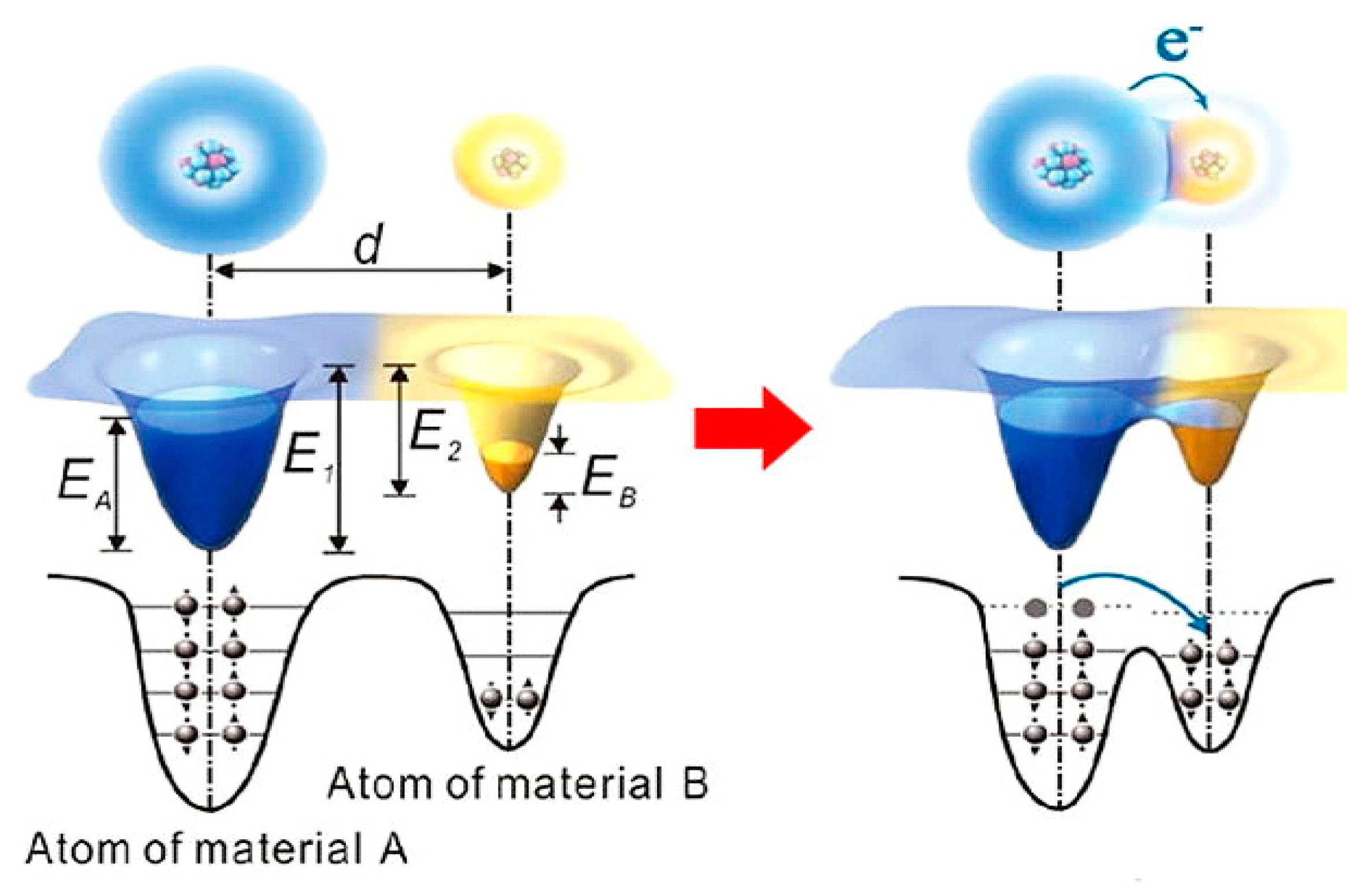
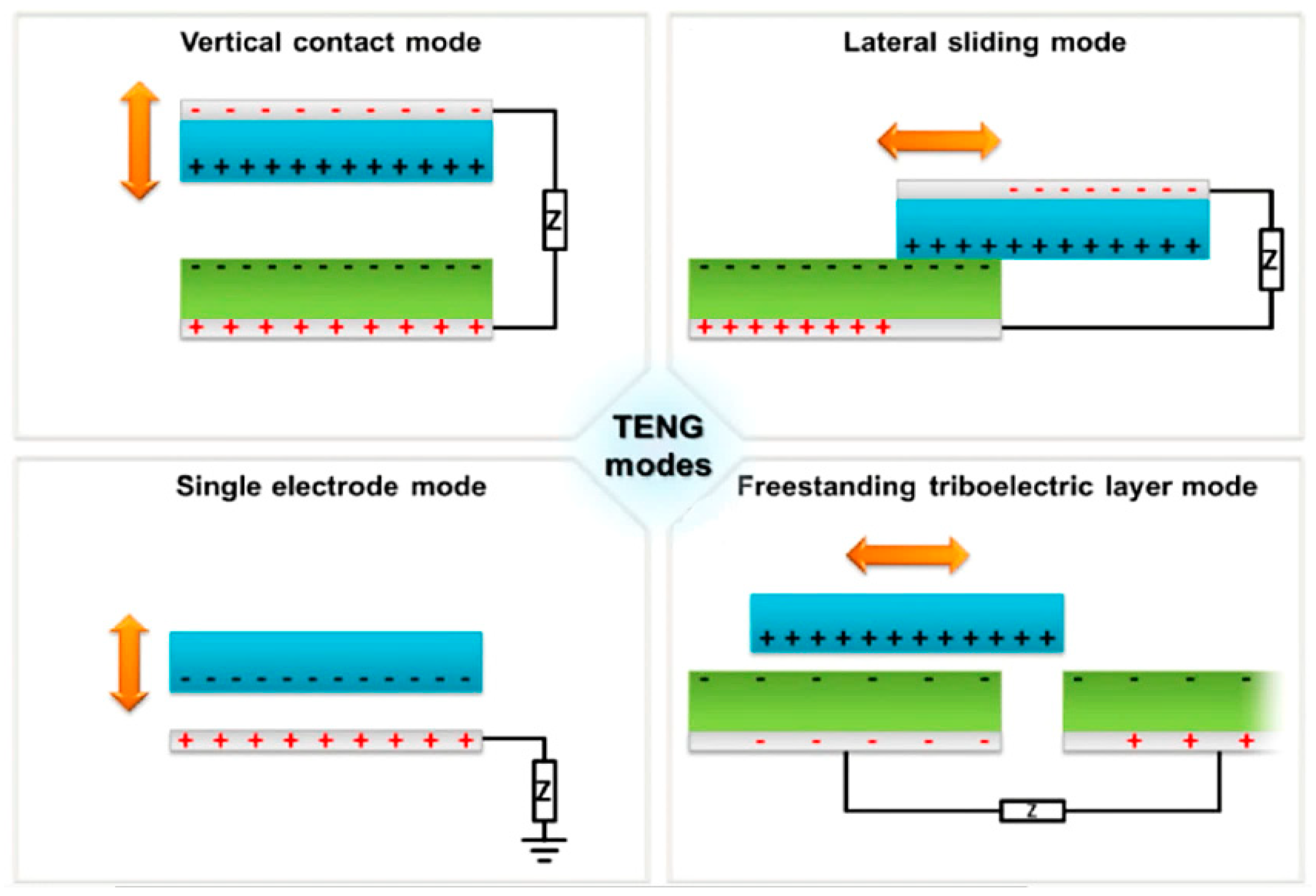
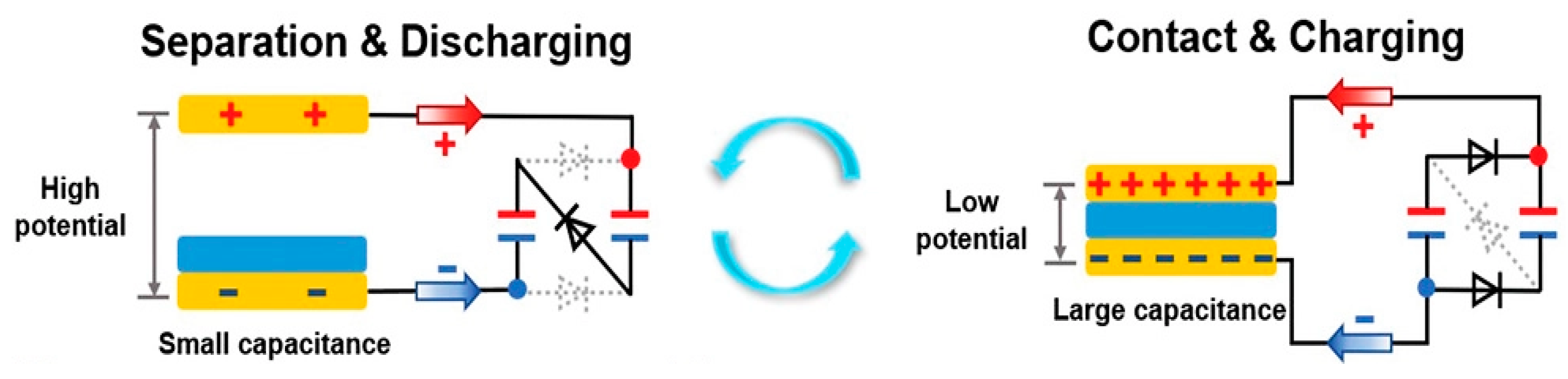
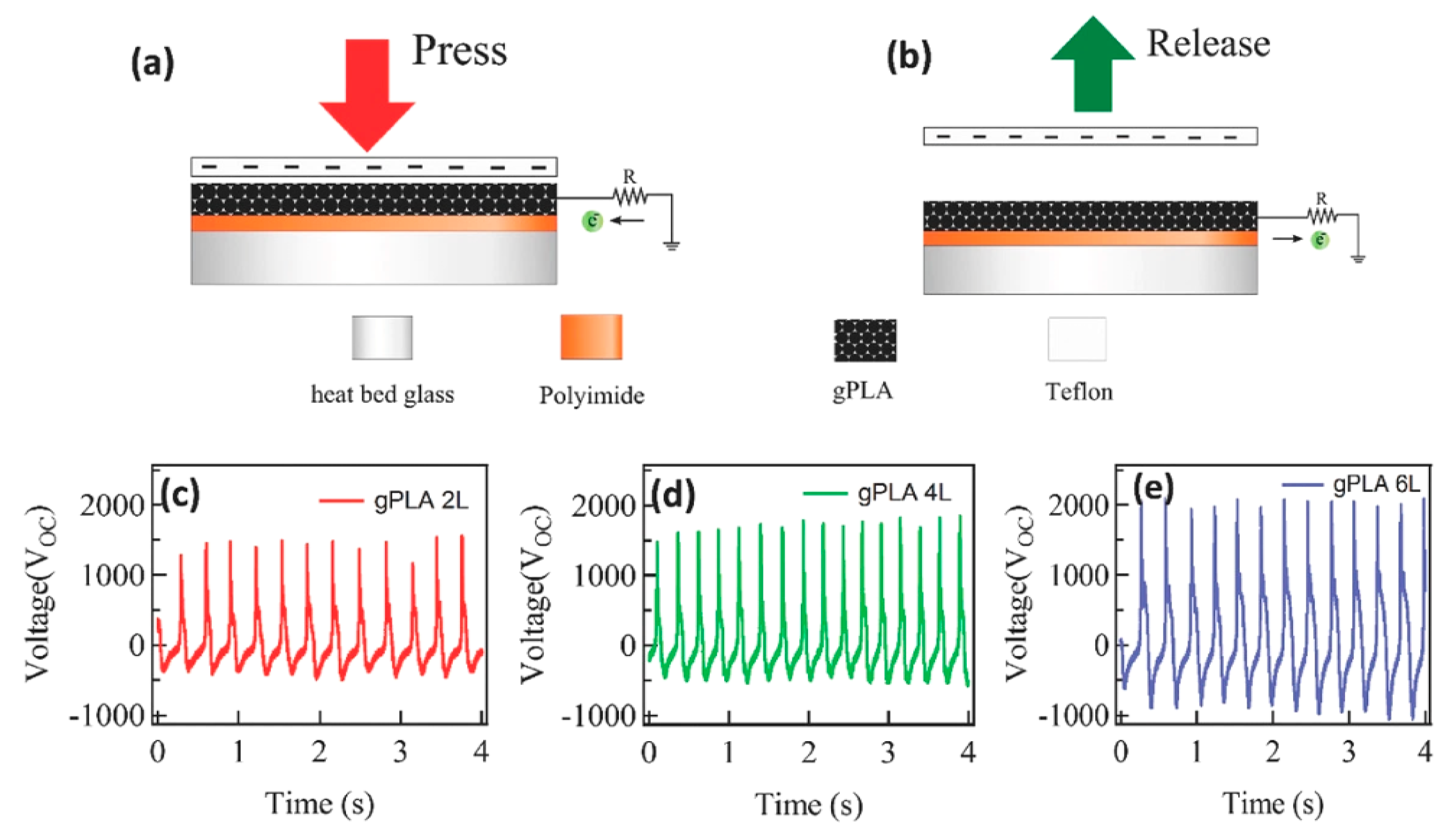
2.1.3. Triboelectric-Based Floor Solutions: Working Principle and Theoretical Fundamentals

The triboelectric effect works by contact triboelectrification and electrostatic induction between two materials featured by different polarities by applying an external force on the tile’s surface, inducing opposite distribution of charges between the layers [45] (Figure 9). There is no overlap between the electron clouds of two materials before they come into atomic-scale contact, and an attractive force occurs. The electrons are so firmly confined in their orbits that they cannot escape. When two atoms in two materials come close together, the electron clouds overlap and create an ionic or covalent bond. An external force can reduce the bond length; the strong electron clouds overlapping causes the energy barrier drop, allowing electron transfer, representing the triboelectrification process. The transferred electrons remain on the respective materials after the two atoms have been separated because energy is required to move them back, resulting in electrostatic charges on the material’s surfaces. The triboelectric effect will introduce stable dynamic charge transfer, held at the tribological interface, featured by capacitive characteristics. Some typical triboelectric materials are polytetrafluoroethylene (PTFE), fluorinated ethylene propylene (FEP), silicone, nitrile, polyethene terephthalate (PET), polydimethylsiloxane (PDMS), metals (Cu, Al, Ni, etc.), skin, graphene, water, etc. [22] The most crucial issue in triboelectricity is to experimentally design the triboelectric series, which gives a broad concept of how charging happens when two materials come into contact via rubbing, pushing, or friction. The greater charge transferred is obtained farther away the two materials are on the electrification scale (Figure 10) [46].
Zhao et al. demonstrated that the polyvinyl chloride (PVC) film, widely used in the industry but not in TENG (Triboelecric Nanogenerators) development, presented optimal performances in terms of surface charge density, polarization strength, friction coefficient, charge’s utilization rate, and stability [47]; this material is suitable for developing DC TENGs, that do not need any rectification circuit. Specifically, the effective charge density for a microstructured TENG based on PVC can obtain ~8.80 mC·m−2, fixing a new TENG’s record.
There are four working modes for TENGs: vertical contact mode, lateral sliding mode, single electrode mode, and free-standing triboelectric layer mode (Figure 11) [48]. In the vertical contact-separation mode, the potential drop is caused by the physical contact and separation of two materials. The electrons flow through the external connection and balance the potential difference. The lateral sliding mode is defined as two materials sliding against one other in a relative parallel motion, producing triboelectric charges and polarization fluctuations with the relative contact area.
In single electrode mode, only the triboelectric material and a grounded single electrode guarantee the potential variations. Lastly, in the free-standing mode, the symmetric electrodes are placed on the back of one triboelectric material, causing the electron flow when another material travels over the surface and generating an uneven charge distribution.
Usually, in energy harvesting tiles, the vertical contact mode is exploited, including two plates covered by the triboelectric materials. Periodic plate’s contact and separation due to human trampling causes friction between them, generating an electric signal, which suitably conditioned, is preserved into a storage device.
Surface charge density σ measures the charge generation on both materials, establishing the triboelectric efficiency of the transducer. It is the basic parameter, determining the surface power density and volume energy density. Furthermore, as demonstrated in the following function, the surface charge density is a helpful metric for linking and analyzing surface capacitance characteristics and interface electrical performance.
V = f ( Q ) f ( A e f f · σ )
where Q is the surface charge on Aeff effective area; the accumulated charge generates a voltage V [49]. Through contact electrification, the contacted triboelectric surfaces show opposite surface charges but with the same density σ (Table 2). The charge polarity and intensity are affected by the materials and other factors, such as surface processing, the surfaces width, contact pressure, rubbing intensity, environmental conditions (such as humidity), presence of contaminants or oxidants, and rapidity with which the contact surfaces are removed. Besides, load stress is fundamental in the triboelectric generation since it binds mechanical and electrical behaviours. Understanding mechanical reactions can provide a solid base and effective tool for developing future triboelectric harvesters. As a result, the triboelectric effect is greatly dependent on the load. Humidity and acidity impact the triboelectric effect concerning ion/polarity generation and chemical reaction. When a hygroscopic surface works in a moist environment, more water or salt will be attracted before/during triboelectric contact, forming a conducting layer, causing charge leakage [49]. The TENG output performances are deteriorated by increasing environmental humidity because of the electrostatic dissipation. This effect is critical for outdoor applications, making them suitable in controlled environments [50]. Furthermore, by increasing the size of triboelectric tiles and connecting more devices in parallel, the output power provided by the energy harvesting floor can be increased.
There are two categories of triboelectric material pairs: dielectric-to-dielectric and conductor-to-dielectric contact (Figure 12) [51].
The following equation expresses the capacitance of the tribo-dielectric layers:
C = Q S C V O C = ε 0 S d 0 + x ( t )
where C and S are capacitance and contact area; d0 the effective dielectric thickness given by the sum of the dielectric thicknesses divided for its relative permittivity εr, as well as x(t) is the distance between the triboelectric layers [51]. Employing a porous dielectric layer in a triboelectric harvester, for example, allows improving the ε/d ratio by jointly raising the dielectric constant and lowering the thickness when the dielectric layer is squeezed, resulting in a considerable increase in surface charge density. As a result, the triboelectric layer’s dielectric constant is a more influential factor in improving surface charge density than the surface potential determined by triboelectric pair material selection [51].
Li et al. in ref [52], have maximised the charge density by improving the charge accumulation process. The charge accumulation rate can be efficiently accelerated via ion injection, charge pumping, and external/self-charge excitation strategies. Despite greater charge decay under high charge densities, the surface charges achieve a higher equilibrium due to rapid charge formation, leading to improved TENG output performance. They proposed a novel solution to obtain a higher charge density of TENG by employing a fast charging process on an insulating layer featured by a high dielectric constant. Exploiting the self-charge excitation and high dielectric permittivity of P(VDF-TrFE) (poly-vinylidene fluoride-trifluoroethylene)), the TENG charge density can be increased to 2.20 mC·m−2. Besides, the contact efficiency was enhanced to 82% by avoiding utilising ultrathin dielectric layers. Exploiting the fast charge aggregation, surface charges achieve a high equilibrium state in humid environments, resulting in steady output performance even under harsh circumstances. The charge density can be maintained at 1.30 mC·m−2, over 260 times that of the conventional TENG, even at 90% relative humidity [52]. One voltage multiplier circuit (VMC), comprising three rectifier diodes and two capacitors, is used to understand better the charge accumulation and transfer processes [52]. External capacitors can be automatically configured in series and parallel during TENG’s periodic contact/separation, obtaining alternate capacitors’ charging and discharging during the charge storage. The external capacitors are configured in series-connected when the two layers are turned away. Meanwhile, TENG’s capacitance drops dramatically as the voltage rises abruptly, causing a charge flow from TENG to the external capacitors. Due to the unidirectional conductivity of diodes, the external capacitors are automatically arranged in parallel during the contact process. TENG’s capacitance rises as the voltage falls, causing a drain of the charges from the external capacitors to the TENG until the potential difference disappears. In the subsequent separation process, external capacitors are changed back to series-connected, forcing charges to flow back from TENG to external capacitors and creating a charge circulation loop. Surface charges achieve a high equilibrium state after a period of rapid charge accumulation. Furthermore, adopting dielectric materials with a proper thickness, higher relative permittivity, and low leakage current improves transducer efficiency (Figure 13).
Finally, a comparison between piezoelectric and triboelectric technologies is reported in the following table. Furthermore, relevant scientific works focus on hybridised nanogenerators that combine PENG and TENG, showing a promising future, leveraging their respective advantages (Table 3) [22].

2.2. State of the Art about Energy Harvesting Technologies Applicable to Smart Floors

2.2.1. Piezoelectric Smart Tiles for Energy Harvesting Applications

Piezoelectric energy harvesters (PEHs) are used in specific applications: smart shoes, tire pressure monitoring systems, artificial pacemakers, and infrastructure monitoring systems. Yet piezoelectric stacks are attracting the interest of researchers due to their following features: low internal resistance, high capacitance, capacity to stand high load (up to hundreds of newtons or more), low resonance frequency.
These features collectively work, allowing piezoelectric stacks to generate very high-power density under large external loads or solicitations. Because the PEH is more efficient when it works near the resonance frequency, a solution employs an auxiliary structure that consists of mechanical support, a cantilever, and a PZT layer deposited on it. Researchers are interested in the frequency-up conversion technology for converting excitation frequency to high-frequency oscillations because it can boost output power.
In ref. [35], Panthongsy et al. presented an energy harvesting floor tile that extracts electric energy from human footfall using a frequency up-conversion method. The structure of the energy harvesting floor tile with the frequency up-conversion mechanism is depicted in Figure 14. The free ends of twenty-four unimorph piezoelectric cantilevers are connected to a stainless-steel mass to enhance the strain in the piezoelectric material and improve electrical output power during oscillation. The permanent magnets hooked to the mass attract the iron bar below the cover plate when the floor tile is trodden on. The impact force between the iron bar and the permanent magnet is absorbed by a soft plastic layer. Furthermore, a stopper protects the piezoelectric layer from damage due to over-displacement excitation. Four springs are placed at the tile’s corners to pull up the cover plate. The resonant frequency is 10.54 Hz, and the mean power and overall produced energy produced by one-foot step on the tile were 1.24 mW and 3.49 mJ, at a 74.44 kΩ optimal load resistance.
In ref. [53], the authors presented a piezoelectric tile using an indirect method of energy transmission based on vibrating cantilevers with a tip mass. The piezoelectric tile consists of an upper plate attached to a middle plate, with four piezoelectric cantilevers (based on PZT-PZNM) of 47 × 32 × 0.2 mm3. Four springs are installed at the tile angles to support the whole structure. This research aims to match the resonance frequency of integrated cantilevers with that of the piezoelectric tile. The conditioning circuit was optimised to get the impedance matching as well as the mechanical structure for obtaining the frequency matching (Figure 15). The experimental results showed that, with a 10 g tip mass, a 22.5 Hz resonant frequency was obtained, and 770 µW RMS was scavenged from the piezoelectric tile using a 15 KΩ matching impedance.
In ref. [54], the authors proposed a mechanism of force amplification relying on linkage mechanism theory to implement an energy harvesting floor. The vertical force was converted into tensile force in the horizontal plane during a foot strike, and the applied force was amplified.
The force amplification device consisted of eight connecting rods connected by joints. The connecting rods’ angles concerning the horizontal plane were the same, and two side joints were also joined by the double-layer structure. A slab was employed as the floor surface on the structure’s upper level. The deforming mechanism is referred to as a “squeezing structure.” A clamped–clamped piezoelectric beam was placed between the two joints and subjected to both tensile and bending stress due to the plates’ deformation and the force exerted by the rubber pillars. In fact, the clamped–clamped beam comprised a 4 × 5 array of piezoelectric modules deposited on two substrates and coupled using rubber pillars (Figure 16). The benefit of the designed architecture is that by carefully adjusting the height of the rubber supports, all of the piezoelectric cantilevers are exposed to wide, equally distributed stressors due to stepping force. Moreover, the double-layer structure will be stretched because of the increased tensile force (Figure 16).
It is simple to conclude that a large improvement in output power can be obtained by increasing the stroke. However, because an extremely large slab stroke might give pedestrians an unpleasant feeling of falling, the slab’s stroke was fixed at 5 mm. The peak-to-peak output voltage was enhanced apparently by increasing the stroke, and the maximum peak-to-peak voltage was 49 V for a stroke of 5 mm. With a step frequency of 0.95 Hz, the tested piezoelectric beam produced a 52.2 V peak-to-peak voltage. The peak-to-peak voltage was 51.4 V when the step frequency was raised to 1.81 Hz.
The test results indicated that the peak-to-peak voltages were relatively stable for different step frequencies. An effective method to achieve an active self-tuning of the resonance frequency employs a microcontroller feed by the piezo element [34]. The natural frequency of the power harvesting device was matched to the excitation frequency of the ambient vibration by adjusting the stiffness of the harvester beam.
In ref. [55], Yingyong et al. proposed a novel mechanical structure for scavenging energy from pedestrian steps, obtaining 35 mWrms output power. At first, they analyzed the walking characteristics of pedestrians in three test fields for sizing the harvesting system, taking into account body weight, walking pace (normal or fast), and pedestrian density. The mechanical structure of the presented EHFT (energy harvesting floor tile) included an aluminium support with 450 × 450 × 58 mm3 dimensions and a 5 mm vertical stroke (Figure 17). Four springs with 16.3 N/mm Hook’s constant support the cover structure, and a rail guide limits its vertical movement. To convert alternating current to direct current, 44 piezoelectric cantilevers were connected to a rectifier.
The accumulated gathered energy was stored in a capacitor. A capacitor was used to store the scavenged energy. The tests demonstrated that the energy scavenged from the piezoelectric EHFT did not depend strongly on stepping frequency but was affected by pedestrian body weight, as well as the pedestrian density had no effect on the harvested energy. Finally, the tests indicated that the system produces about 24.6 mJ/step.

2.2.2. Electromagnetic Harvesters for Large-Scale Power Production and Road Pavement Energy Harvesters (RPEHs)

An electromagnetic (EM) harvesting system was proposed by Jintanawan et al. whose intuitive block diagram is shown in Figure 18 [36]. It converts the platform linear translation induced by the footsteps in rotative energy for the electromagnetic generator (EMG) with a mechanical system of translation–rotation conversion. Researchers worked on two prototypes, the first was based on a rack-pinion model and the second on a lead-screw model. The second was more efficient than the first. The rack-pinion and lead-screw configurations are commonly used to change the translation to rotation (Figure 19).
The rack-and-pinion transmission system consists of a rack fixed to the machine’s side and a pinion gear or gear/gear that matches up with the rack; EMG moves as the pinion turns. The lead-screw drive systems act similarly to standard power screws, but the sliding friction is substituted with a rolling friction. The machine moves as the screw revolves. A rack- and-pinion transmission system is cheaper than a lead-screw system, is more efficient to convert energy, and is robust, but with more friction. Only the rough-pitch models were reported in the literature, thus limiting the angular pinion movement to the rack’s allowed displacement of 15 mm.
Nowadays, EM harvesting technology can be applied to road pavements. Duarte et al. proposed a mechanical system to convert the energy of the vehicle’s wheels into electrical energy [56]. Two systems are mainly used to achieve a rotational motion output: the rack-and-pinion and the lever systems (Figure 20). The first is the most widespread, but the lever system has the benefit of amplifying surface motion, but the increase in motion comes at the expense of force. Therefore, the lever geometry must be carefully designed.
A more efficient system would maximise both the transmitted force and shaft rotation, with the transmitted force taking precedence. A mechanism using a crank connected from the surface to a slider is presented for this aim (Figure 21). For the same scenario, the results show that it is two times more efficient than the rack-and-pinion system and four times more efficient than the lever method [56].
In ref. [57], Zhang et al. develop a rotational electromagnetic harvester. It is mainly composed of a twist driving system and a ratchet clutch system (Figure 22).
In the twist driving system, a double-helix structured rod passes through a circular disk with a dumbbell-shaped hole, and four guide rails limit the rod’s movement direction. Due to the interaction between the twist rod and the hyperboloid hole, the twist rod spins with the pawl when it is pressed perpendicular to the disk. Thus, the linear motion becomes a ratchet-rotational motion. Spring is also employed to return the twist rod to its original position. The test results indicate that the ratchet may rotate inertially for around 20 s, yielding total energy of 85.2 mJ; furthermore, 32.2 mW peak power output and 7.7 mW root mean square power can be generated (Figure 23).

2.2.3. TENG and Hybrid Energy Harvesters Evolution in Small-Scale Power Production

Essential characteristics of TENG in smart floors are the easy integrability but also limit the power outputs. For instance, He et al. [58] developed a triboelectric smart floor; to avoid abrasion and frictional heating in the contact mode, the TENG can operate in no-contact mode by separating triboelectric materials from electrodes spatially. The smart tile relies on an SF (Square frame) TENG using triboelectric materials such as polytetrafluoroethylene (PTFE) sheets and aluminium (Al) spheres, as well as the floor itself and things that come into touch with it (for example, basketballs, shoe bottoms, scotch tape, and so on). Indeed, the proposed tile supports two working modes. In mode I, vibrational energy is harvested: when the TENG is subjected to an external force or vibration, the inner Al spheres oscillate between the top and bottom planes, pushing electrons to flow via the external circuit. When the Al balls come into touch with the PTFE films, the triboelectric effect causes electrons to flow from the Al balls to the PTFE films. In mode II, the smart floor offers a different method for harvesting energy from human activities, such as running and dancing, since it exploits the interactions between the floor and things made of triboelectric materials (Figure 24). The experimental results showed that TENG provided 364 ± 43 V with 9 ± 1 μA current when a basketball is bounced repeatedly on it and 238 ± 17 V with 2.4 ± 0.3 μA current during walking.
However, the power output is low for energy harvesting, and the best technology for the smart floor depends on the application typology and its power consumption [59]. To optimise the mechanical energy generation and thus maximise output power, research teams worldwide have developed hybrid nanogenerators (NGs) with different and novel structures, including triboelectric, electromagnetic, piezoelectric, thermoelectric, pyroelectric transducers. Generally, TENGs are considered efficient energy harvesters for energetically-autonomous sensors [60]. The hybridization of different NGs offers an efficient approach to enhancing the output powers by simultaneously harvesting multiple energy sources. Hybrid energy harvesting (HEH) systems are classified into multi-source hybrid harvesters and single-source harvesters.
The combination of TENG and electromagnetic generator (EMG) appears to have the potential to compensate for the limited energy harvesting capability of EMG at low mechanical frequencies. Islam et al. presented a hybrid floor-tile to harvest the biomechanical energy from human footsteps (Figure 25) [61].
The electron flow across the magnetic field of the magnets is enhanced when a conductive wire is coiled in a series circuit, resulting in an EMG current. The electromagnetism of a coil increases proportionally to the number of turns, and the magnetic field is stronger as the magnet’s size increases. The hybrid system comprises coils of 20 turns to ensure minimal tile compression and user safety. The triboelectric effect relies on electrostatic induction and contact triboelectrification between two materials of different polarities following an external force on the tile. The Al electrode is positively charged during the contact phase due to contact triboelectrification between Al and Kapton, whereas the Kapton layer becomes negatively charged when combined with the MoS2 (molybdenum disulfide) layer, acting as an electron acceptor and aiding in the triboelectrification of contacts. Meanwhile, the top electrode becomes positively charged due to contact triboelectrification with the top Kapton surface. The upper component begins to separate from the lower Al layer as the applied force is released; at this point, a voltage difference between two electrodes can be observed (Figure 26).
As previously indicated, EMG creates more current, whereas TENG generates a higher voltage; the combination of TENG and EMG is the ideal combination for our investigation for a floor tile construction thanks to their low cost, high efficiency, and simple design. The EMG generates power when the two tile layers come into touch, whereas the TENG produces energy as the two layers separate, reaching for each footstep, 5 mA short-circuit current and 1200 V open-circuit voltage. Besides, environmental sustainability, packaging concerns, and pedestrian safety have been taken into account in this new, ground-breaking study.
The test results demonstrated that the storing capacitor was charged to 15.12 V in 60 s ÷ 80 s time interval. However, although the tile produced up to 1200 V, capacitors cannot store this high voltage value, indicating that the presented device is suitable for large-scale installation, where a battery and generator would be more applicable. Furthermore, the authors compared the developed energy harvesting tile with a competitor product (i.e., Pavegen), showing that the first one generated 25 times greater open-circuit voltage and 20%. Furthermore, their design employs a specified coil size to generate a robust, flat tile, guaranteeing the safety of human walkers with a compression of just 1 mm, unlike Pavegen’s 5 mm.
Another way to hybridise TENG is by using piezoelectric material. Zhao et al. integrated a bimorph-based PENG into a one-end-fixed TENG [62]. Harvesting mechanical energy in arbitrary modes (e.g., periodic bending, vibration, rotation, etc.) for sustainable portable electronics, advanced wearable sensors, and self-powered systems appears to be very promising. To gather rotating mechanical energy, the developed H-P/TENGs were placed on three upright posts of a bespoke frame (stator) and were exposed to bending forces from a coaxial tri-blade structure (rotor). The presented device shows both strengths of TENG (low-frequency energy harvesting) and PENG (high output power), which is fundamental for stably supplying electronic devices. The device can deliver 210 V open-circuit voltage, 395 μA short-circuit current, 10.88 mW average output power, and 6.04 mW/cm2 power density. Besides, it can provide 210 V/400 µA at rotation speeds ranging from 50 to 250 rpm. They integrated an energy regulating circuit with the H-P/TENG to create a DC power supply (3.6 V steady DC output voltage) to feed an RF wireless temperature sensor network and commercial devices. At a wind speed of 14 m/s, the H-P/TENG could produce high output voltage (150 V) and current (150 µA) to power 50 LEDs in parallel.
In another study [63], Chen et al. demonstrated a rotating-disk-based hybridised electromagnetic-triboelectric nanogenerator that scavenges rotational energy and acts as a power source for WSN applications. The device is made up of a TENG with rotating and stator layers, an EMG with six magnets on the revolving layer, and six copper coils aligned with magnets behind it (Figure 27). Particularly, circular acrylic support, including six magnets, is comprised in the EMG. The rotator’s multilayered structure includes a printed circuit board (PCB) with 1° radially distributed Au sectors in close contact with a foam layer for the TENG. Its operation is based on periodic rotation between rotator and stator, including the TENG and EMG. In the EMG, there are four groups of rotating magnetic coil pairs, each of which may produce an alternating current by changing the magnetic flux in the coil using faraday electromagnetic induction. The functioning mechanism of the TENG component is based on triboelectrification and electrostatic coupling, which can cause inductive electrons to flow across electrodes.
To quantify the performance of the hybridised nanogenerator, it was operated by a governor motor; by using a rotating rate of 900 rpm, the hybrid generator provided 137.39 mW output power (power density 180 μW g−1) to a matched load resistance of 300 Ω and 217.8 mW (power density 1152 μW g−1) to a 20 kΩ matched load. The harvested power was wirelessly transmitted to a user device; the transmitting antenna comprises a hollow inductance coil and a top capacitor (Figure 27); the receiver gathers the power employing the same principle. The developed wireless power transmitting system was used to charge a mobile phone 100 cm away from the transmitter using a pair of specialised helical wire coils and a supercapacitor bank (Figure 28).
Increasing the conductivity of the polymers of the electrodes is another simple technique to maximise power output using sustainable materials. Despite the huge voltage spikes caused by charge separation, non-conductive polymers yield poor electric currents. Mallineni et al. improved the output current by depositing conductive indium tin oxide on their W-TENGs [64]. A 3D printed microstructured film of graphene–poly (lactic acid) (gPLA) was deposited and connected to a Teflon layer to construct a TENG (Figure 29). The W-TENG produced significant output voltage (>2 kV) and peak power (>70 mW at 10 MΩ) when triggered by simple mechanical movements like hand tapping.
By applying a 120 N force with a 3 Hz average frequency, the W-TENG generated a high voltage output and strong electric fields, enabling wireless transmission without any external power source. The wireless signal processing section comprises a preamplifier (i.e., LMC6001), an intermediate amplifier (i.e., TL082), and a pulse-shaping relying on the NE555 IC. To reduce interference from the surroundings, a band-pass filter made up of passive single-pole low-pass and high-pass filters was employed.

3. Commercial Smart-Floors and Components for Energy-Harvesting Applications

This Section will present the existing commercial technologies and devices for energy harvesting by human footsteps, with their costs and performance, discussing the technologies behind these systems, already introduced in the previous Section.

3.1. Transduction Mechanisms, Conditioning Sections, Operational Strategies Applied to Smart Floor Applications

The market for energy harvesting systems is expected to be worth USD 468 million in 2021 and USD 701 million by 2026, with a CAGR (compound annual growth rate) of 8.4%. The rising demand for safe, energy-efficient, and long-lasting and maintenance-less systems, the increasing use of IoT devices in automation and harvesting systems for home automation, as well as favourable government initiatives and the rising WSNs’ adoption equipped with harvesting systems are prominent trends. COVID-19 has had a low impact on the energy harvesting industry, but with so many service providers and integrators involved in dealing with the unprecedented pandemic, harvesting systems’ adoption may be slower than expected in the short term. The United States is a major hub for energy harvesting systems in construction, residential, and industrial automation applications. In the manufacturing industry of energy harvesting systems, Europe is home to prominent enterprises. The major players in the energy harvesting system market are ABB (Zurich, Switzerland), Linear Technology (Milpitas, CA, USA), ST Microelectronics (Geneva, Switzerland), Texas Instruments (Dallas, TX, USA), Cymbet (New Brighton, MN, USA), Convergence Wireless (Newport Beach, CA, USA), Fujitsu (Tokyo, Japan), EnOcean (Oberhaching, Germany), Honeywell (Charlotte, NC, USA), and Powercast Corporation (Pittsburgh, PA, USA) [65].

3.1.1. Pavegen’s Tiles

Pavegen is a device developed by Laurence Kemball-Cook that transduces kinetic energy from trampling into electrical energy. He started the development in 2008, and over 750 prototypes were created [66]. The first model consisted of piezoelectric blocks in various shapes to be used in outdoor and indoor pavements. When a person walks across a Pavegen slab, a small displacement (up to 5 mm) is produced on the vertical axis, enough to generate electrical energy (Figure 30). These blocks were employed to produce electrical energy for pedestrian lighting, navigation solutions, public illumination, outdoor advertising, traffic signals, and electrical device supply, among other things, on municipal sidewalks. The pavement block’s top surface was composed entirely of recycled tire rubber, and the base was made up of more than 80% recycled materials. Because the blocks were waterproof, they could be used in both inside and external contexts. Ideal locations to apply these blocks included busy streets, transport hubs, busy train stations, offices, events, schools, shopping centers, pedestrian crossings, etc. [67]
Seow et al. analyzed and tested the first model of the Pavegen tile [69]. They found no economic advantage in installing it because the cost of the tile had been recuperated after 444 years of saving money in electrical energy [69]. One to seven watts are produced by a foot stomp that depresses a single tile by five millimeters. These tiles use a hybrid approach that involves the piezoelectric effect and induction and copper coils and magnets to generate electric power. The new Pavegen technology, called “V3”, is sleeker and more efficient than the first generation. It consists of a triangular basement with an electromagnetic generator at each corner [70]. One footstep generates enough off-grid energy to light an LED lightbulb for about 20 s. A wireless API (application program interface) sensor is also included in the tiles to communicate data related to movement patterns in places where Pavegen is deployed.
This system could be used to estimate peak pedestrian traffic hours in a given location, forecast consumer patterns, and produce heat maps of popular urban areas. The tiles track people’s position and the number of steps they’ve walked in real time, which companies might utilise to track client movements [68,71,72].
Pavegen has been successfully installed on two local football fields in Brazil and Nigeria. In 2013, Pavegen installed its kinetic tiles on the final stretch of the Paris Marathon, in which participated 40,000 runners and generating 7 kWh as they crossed the finish line [71]. In Figure 31 is reported a detail of the Pavegen’s installation. Other installations can be viewed at the following link, www.pavegen.com (accessed on 1 June 2021). Piezoelectric technology in the form of kinetic tiles, smart speed absorbers, and reactive flooring could power everyday life systems in the near future: roads, pathways, public transportation, and more. Smart flooring energy can be used in conjunction with other renewable energy sources like solar and wind to minimise their susceptibility to changing weather. Multiplying the number of simultaneous renewable energy sources is the key to making the future green while using solar, wind and hydropower large-scale kinetic flooring is unnecessary.
These kinetic floor tiles can provide more energy by installing them in specific high traffic areas to power surrounding equipment as needed. Because this technology is self-sufficient, the Pavegen tiles would save roughly 50 ktons of CO2 emitted in the atmosphere and make street lighting immune to power outages [71]. Ref. [73] reports Pavegen’s tile patent, ref. [74] the electromechanical generator patent. The tile is triangular, slightly truncated at the corners and supported by three supports; it has an equilateral triangular shape because if a user steps on the corner of a squared tile, there can be a displacement on the opposite corner. These deformations that can produce trip hazards are avoided using the triangular shape. The longest dimension of each tile is from 300 to 700 mm. The thickness has to be small, the core material can be Nomex, polypropylene, fiber-reinforced cement. The top and bottom layer can be steel or laminated ceramics, with an additional top layer of decorative or resistant material. There is flexible sealing to prevent the entry of solid or liquid materials between the tiles, made by rubber, neoprene, TPV (Vulcanized Thermoplastic Elastomer), TPE (Thermoplastic Elastomer) or polymeric materials. The movement range is from 5 to 10 mm. Each tile is supported by gaskets with a cap on top. To prevent the relative translating of the support, an O-ring made up of rubber or polymeric material avoids the hard contact between the cap and tile. The flooring system has a data processing section that communicates with the generator acquiring the electrical power used to estimate the number of people on the tile crossing the floor and recording the time and location of each footstep. This operation is possible by comparing the output value of the three generators recorded and used to estimate the footstep location. The tracking algorithm for the footsteps localization can be the Kalman filter or a probability hypothesis density tracker. The tracking algorithm can input the location, the footstep direction, the magnitude and the user’s estimated mass.
Additionally, the flooring system can have electromagnetic receivers to receive RFID, Bluetooth or Zigbee identifier signals of mobile phones with an app that generates it. The Pavegen tile has a base with drainage holes to provide a path for the entry liquid on the base. The electrical generator comprises a housing, an actuator movable axially relative to the housing by an axial distance of between 5 mm and 10 mm, a rotatable member being rotatable relative to the housing and configured to cooperate with the actuator such that axial movement of the actuator causes rotation of the rotatable member. Furthermore, a stator is included in the generator, as well as a rotor configured to receive rotational kinetic energy from the rotatable member. In particular, the rotor and stator are configured to interact such that rotation of the rotor relative to the stator results in electromagnetic induction in the rotor and/or the stator, which produces a three-phase alternating current. Furthermore, the electrical generator further comprises: an electronic circuit comprising a rectifier (flyback converter) configured to convert the alternating current to direct current and a current controller configured to regulate the direct current to be a fixed constant current of between 150 mA and 500 mA. The electromechanical system used to convert linear translation in rotative movement is the ball screw.

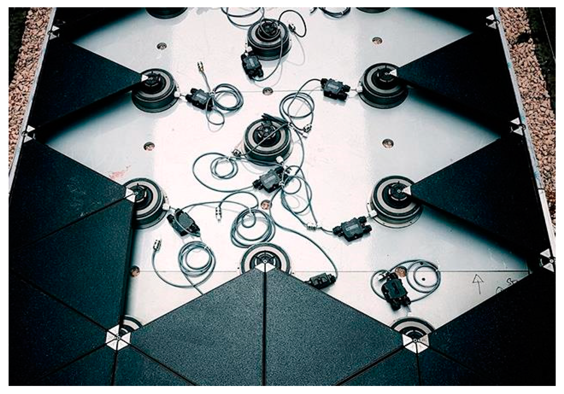
3.1.2. Sustainable Dance Floor by Studio Roosegard

An innovative product is the Sustainable Dance Floor® produced by Studio Roosegaarde [75], a modular system of 65 × 65 × 30 cm3 able to produce 25 W per module to power the lighting and DJ booth (Figure 32) [75,76]. When a person dances on the tile, springs come down, and the rack drives the pinion that rotates the dynamo shaft.

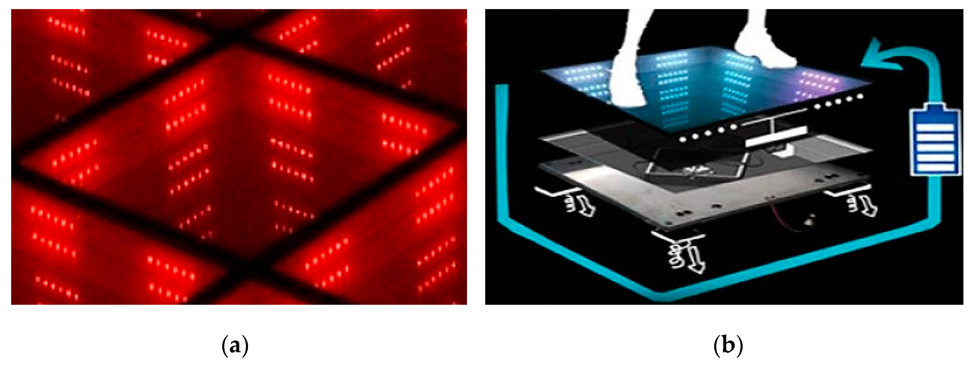
3.1.3. Smart Energy Floor by Energy Floors

Sustainable Energy Floor® (SEF) was the first smart tile model created by Energy Floors [77]. It could produce 2–20 J per step, depending on the user’s weight, movement type, and maximum deflection of the SEF module. It can have a maximum static load of 25 kN. Each tile is 500 × 500 × 100 mm3, and the core (450 mm × 450 mm) is made of recycled ceramics or rubber, glass, bamboo or synthetic materials. The battery pack had a 7 Ah capacity and a 6–12 V voltage (depending on the application’s power consumption). Tiles can be integrated on the existing floor and customised [77]. The second SEF version was born in 2018 from Energy Floors company, called Smart Energy Floor®, available in three models: the Dancer, the Gamer, and the Walker. They are based on an electromechanical solution, based on a rack-pinion mechanism that converts linear tile translation in the rotative movement for the EM generator (Figure 33). The Dancer floor module produces up to 35 W. The Walker comprises walkable solar top modules, and a built-in LED illumination system; each tile has a size of 60×60 cm2 [77]. The Gamer is made up for children education, health and fitness [78].

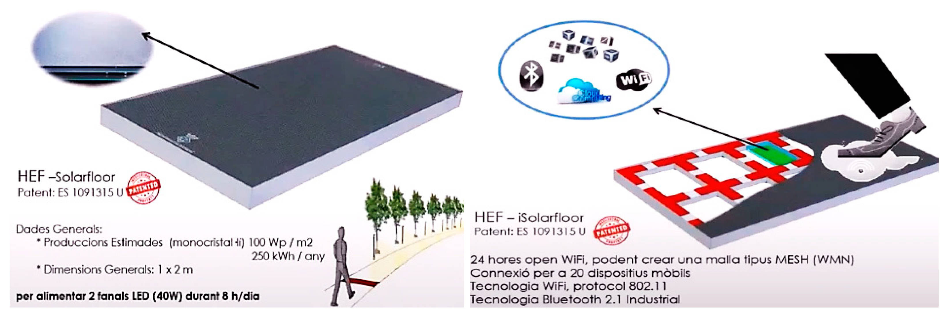
3.1.4. Hybrid Energy Tile by OTEM2000

The Hybrid Energy Tile® (HET) is a new-generation urban flooring that combines Kinetic and PV Solar techs (Figure 34). The clean energy solutions are installed at first at Rotterdam’s Energy Floors showroom. The HET is made up of a top layer of walking solar tiles (invented by OTEM2000, Spain) and energy floor tiles that convert kinetic energy from human movement into electrical energy (developed by Energy Floors), to be installed in commercial streets, public squares, parks and pavements. The tile is available in different formats: 500 × 500 mm2, 750 × 750 mm2, 1000 × 2000 mm2.
Several HEF® (Hybrid Energy Floor®) are deeply discussed in [79]: Urban Solarfloor® and the other solutions are nonslip flooring certificated. Sport Solarfloor® and Solar Sport Courts® developed together ASB Glassfloor [80]. The iEPAS® tiles, developed by OTEM2000, are based on piezoelectric materials and electromechanical systems to scavenge the mechanical energy related to footsteps (Figure 35) [81]. Similarly, the EVELRED® (Energy Speed Reduced) has the shape of a road bump and allows to scavenge energy from vehicles passing over it by using an electromechanical generator [79] (patent available in ref. [82]).

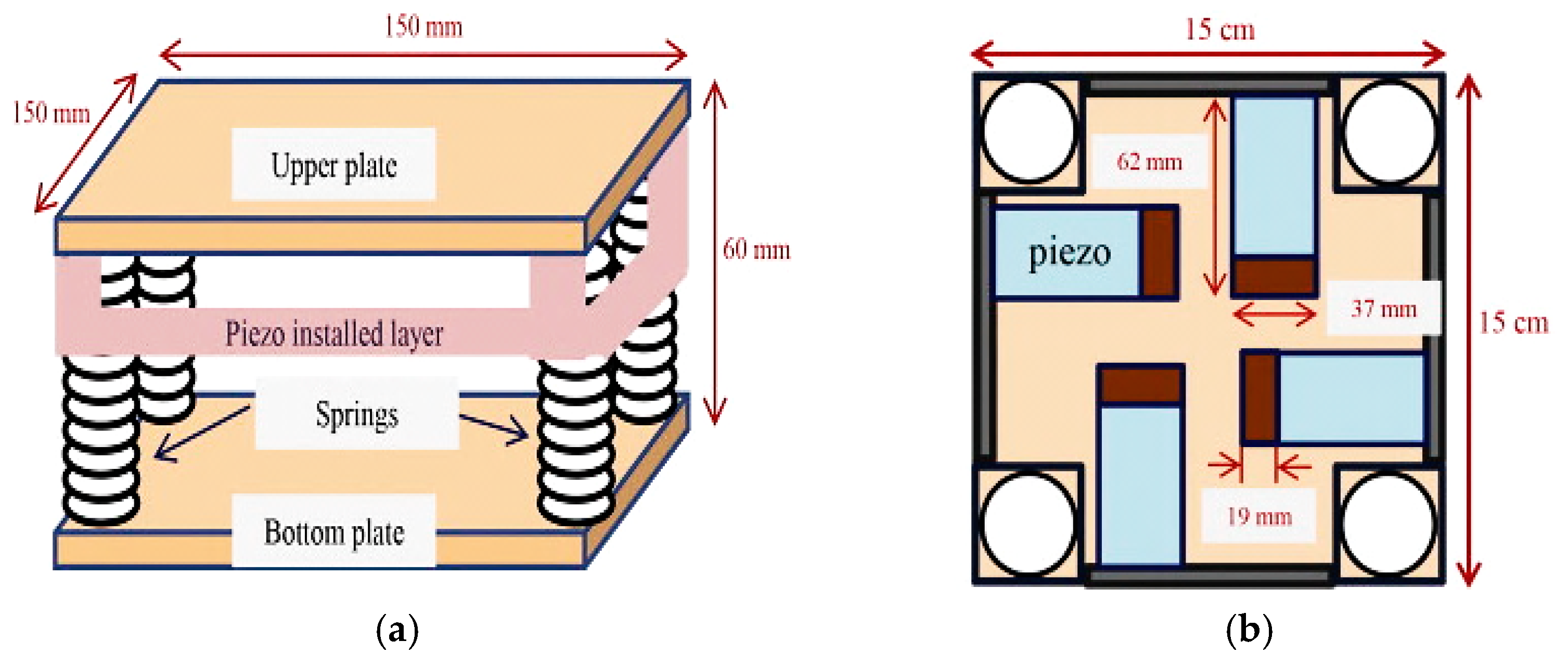
3.1.5. Smart Energy Floor by Veranu

Veranu® is an Italian startup founded in 2015 [83]; the Veranu tile measures 30 × 30 × 4 cm3 with a weight of approximately 1 kg (Figure 36). The tile is made up of a plurality of piezoelectric stacks, each realised overlapping different elements, and elastic insulating spacers interposed between each pair of adjacent piezoelectric elements that favour the tile performance. There are five piezoelectric elements made up of PIEZOTITE® polarised to be connected in parallel. The wiring required to connect the piezoelectric elements of each piezoelectric stack converges into an electronic control unit that allows the signal produced by the piezoelectric stack to be converted in electric current. Moreover, this energy is used to feed a temperature sensor, a wireless transceiver, a pressure sensor, a pedometer, a lighting system, or a motion detector [83]. The released results indicate that the Veranu tile can produce up to 2 W of power/footstep; 20 steps are enough to turn on a street LED lamp and ten thousand to fully charge a smartphone’s battery [84,85,86].

3.1.6. Waydip Company’s Tiles

In 2009, the Waydip startup presented Waynergy, an energy harvesting pavement converting mechanical energy into electric energy, designed in partnership with the Pavement Mechanics Lab of the Coimbra University [87]. This system consisted of various-shaped modules that included an electric power generating device scavenging energy from a limited vertical axis displacement up to 3 mm when a person or vehicle passed over it [88]. The vertical pavement displacement actuates a mechanical gear system (rack and pinion) connected to the generator shaft. The pavement comprises on its base resilient support elements maintaining the tile horizontal. Its output performances (power, W) are reported in ref. [88] as function of the foot support type and user weight.

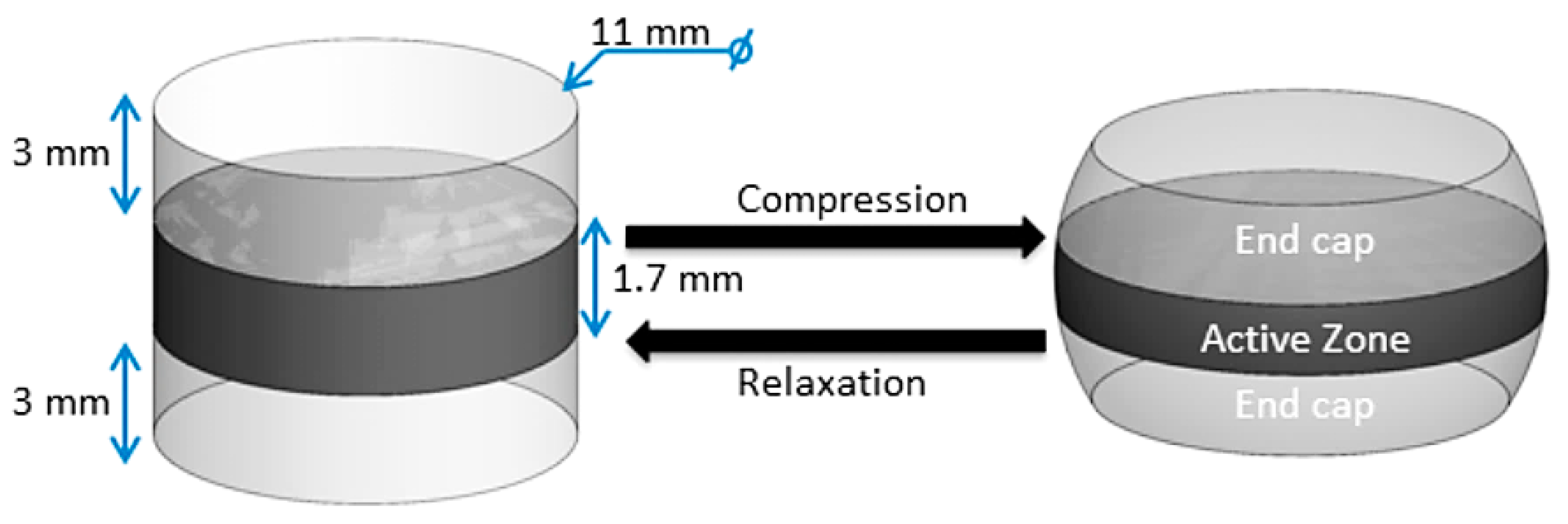
3.1.7. EAP: Electro-Active-Polymers

Electroactive polymers are materials with both sensing and actuation capabilities. They are ideal alternatives for operating as sensors and actuators because of their high strain rate, rapid reaction, robustness, and high mechanical compliance under severe manufacturing environments. Bashir et al. investigated the general operating processes of several electroactive polymers using their individual features and variables influencing their properties [89]. They are used in biomedical, structural health monitoring, aerospace, defense and robotics applications. DE (Dielectric elastomers) have displayed energy densities as high as 550 mJ/g; they are based on films with thicknesses of tens to hundreds of micrometers, thus large area generators are required to provide useful power. Unlike piezoelectric or electromagnetic generators, which struggle to adjust to millimeter- or meter-scale, DEGs (Dielectric Elastomers Generators) can be practically modified to multiple dimensional ranges, allowing various applications ranging from human motion to renewable energy harvesting [90]. DEGs are a very promising energy conversion technology since they feature the following features: (1) an intrinsically cyclical working principle that closely matches the mechanical energy’s alternating/time-varying quality; (2) high energy densities up to 3 J g−1 in theory and 0.78 J g−1 in experiments; (3) a convertible energy density that is theoretically independent of running frequency; (4) low raw material costs; (5) small weight, architectural simplicity (with few or no moving rigid parts), and quiet operation. Failure modes like electrical breakdown (EB) and voltage loss limit the DEG’s performance, material features, and other phenomena, including material extensibility and viscoelasticity, loading configurations, and current leakage [91].
In ref. [92], McKay et al. proposed an electroactive-polymer energy harvester for wireless sensor networks, composed of a stacked membrane configuration that allows self-supporting generators to be fabricated without rigid frames with a much smaller footprint than that needed using a single membrane. The end caps were provided because adhering to the stack ends between two structures is the most practical way for tying a stack to a load. The constrained ends do not deform as much as the central stack. The transducer scavenges energy by moving electrical charges using mechanical deformation as depicted in Figure 37; at a 0.5 Hz frequency, the generator generates 300 µW.
However, no companies are selling commercial DEGs for human footsteps but are instead producing dielectric elastomer materials. Large-scale manufacturing and commercialization are being pursued by some companies, including Aisin AW and Zeon Co. [93].

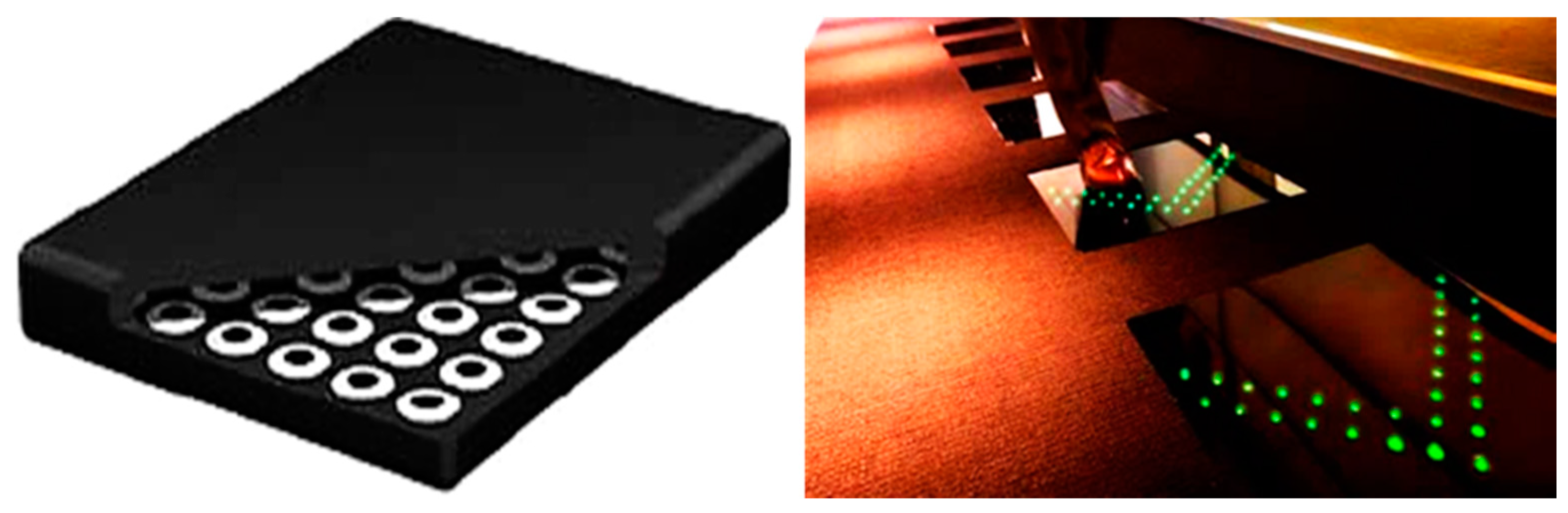
3.1.8. POWERleap Tiles

During her fourth-year thesis at the University of Michigan, E. Redmond, founder of Powerleap Inc., designed new floor solutions for smart sensing and power generation. Powerleap employs a piezoelectric generator to harvest power from human footsteps [94].
Piezoelectric materials scavenge energy from vibrations instead of employing mechanical displacement like magnetic motors and micro-turbines do, thus eliminating the need for moving components. The tile includes two energy devices based on polarised polyvinylidene fluoride (PVDF) layers sandwiched between a set of electrodes that generate current into and/or out of the piezoelectric layer when stressed. Alternatively, the piezoelectric generator can be made of one or more lead zirconate titanate harvesters in a stack configuration separated by electrodes, obtaining a wound piezoelectric stack of multiple piezoelectric layers. The electrode can be a metallic (e.g., copper, aluminium) foil, conductive ink, or any other conductive material. Besides, the two energy devices comprise a Bluetooth transceiver for transmitting information related to the scavenged power to an external receiver. An RFID (Radio Frequency Identifier) reader creates transient electromagnetic fields for feeding the RFID tags attached to each item in the customer’s shopping cart. The unique IDs are subsequently transmitted in the form of data packets to a central server within the store, where the customer’s footfall likewise powers the wireless transmitters. The product characterization indicated that the developed tile can generate 10 W/m2 per hour, corresponding to about 1 kWh per hour from 100 square meters with about 3000–5000 people each hour. The target price ranges from $50–100 per square foot [95].

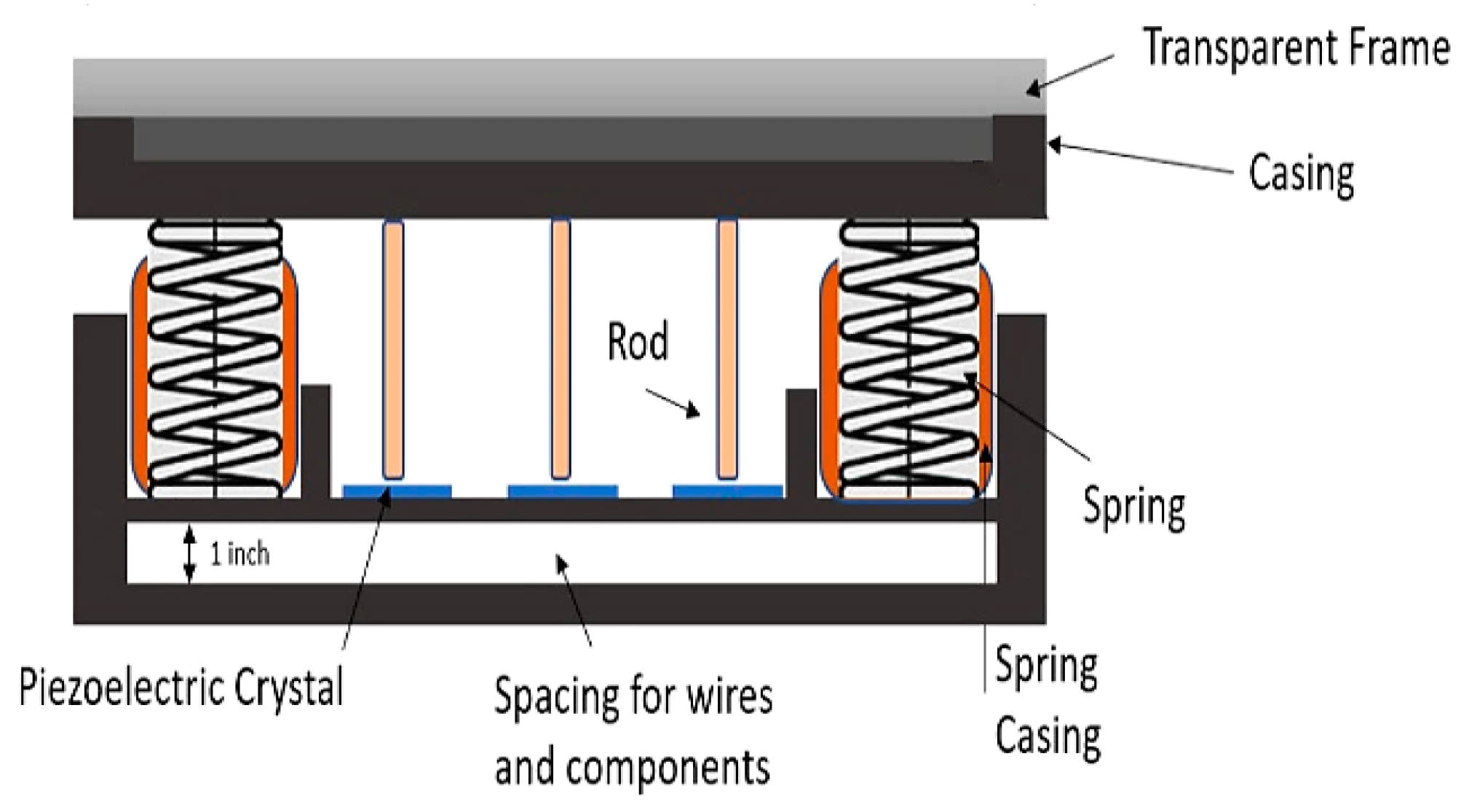
3.1.9. Power Generating Floor by Sound-Power

In 2008, Soundpower developed its Power-Generating FloorTM, and in July of that year, corporate office design firm Kokuyo Office System Co. installed Power-Generating Floor tiles in its offices. Each tile covers a surface of about 50 cm2, made up of a crystalline piezoelectric substance (Figure 38). The Power-Generating Floor consists of tiles that transduce vibrations created by pedestrians or cars passing overhead into electric energy [96,97]. The harvested energy from tramping feeds green LED lights integrated into the tiles, which is triggered when the tile is tramped on, and is used to illuminate the walkway. The tile has a remote controller with operation buttons, a transmitter, a memory, a timer, and a detector. The tile includes the piezoelectric power generator and the power supply section with the bridge rectifier recharging circuit. The power generator includes an ionic polymer-metal composite (IPMC) made by plating both sides of an ionic conducting polymer film (gel) with a metal (such as gold), anionic conducting polymer gel film (ICPF). The pair of piezoelectric devices generate electricity when deformed by pressure, formed of a piezoelectric ceramic, such as barium titanate or Zirconia, or a piezoelectric monocrystalline, such as lithium tantalate (LiTaO3). A rotating shaft is used to return to the original position after the press down. The detector is an operation detection method for detecting when any operation buttons are pressed by sensing output current from the rectifier. The timer measures support time under the control of the operation identification unit. This last detects the operation performed on the operation buttons and determines the subsequent operation depending on which operation buttons have been pressed and the measured support time. The memory is used to store information needed for the controller in a nonvolatile manner. An operation identification table, previously stored in the memory, was used to recognise the user’s activity based on the selected operation type and the pressed operation button. The transmitter wirelessly transmits an operation signal that corresponds to the outcome of the operation identification unit.

4. Comparative Analysis and Discussions

In Table 4, we have summarised all the commercial smart floors previously discussed in terms of transduction mechanism, main features, size and output performance. As can be noticed, for those applications that require a power output in the range 3–7 W, the electromagnetic transduction mechanism, hybridised with piezoelectric or triboelectric harvesters, is the most promising solution for developing floors for energy harvesting applications. They provide significant advantages, simple realization and maintenance, relatively low cost, the possibility of employing ecological materials for the pavements and, finally, the realization of very compact and efficient devices, allowing an easy integration inside existing structures and buildings. On the other hand, electromechanical systems that convert the linear motion of the tile surface into a rotative motion for an electromagnetic generator are efficient but require a more complex design.
Compared to similar review papers reported in the literature, the proposed scientific work focuses on energy harvesting floors for scavenging energy from human walking, presenting the fundamentals related to the main transduction mechanisms applicable in this field (i.e., piezoelectric, electrostatic, electromagnetic, etc.), pointing out for each technology strengths and weakness. Besides, an up-to-date overview of scientific works related to energy harvesting floors based on presented technologies and corresponding hybrid solutions is presented, not limited only to the piezoelectric transduction mechanism [11,13]. According to us, the strength of our review paper is to extensively focus only on smart floors able to harvest mechanical energy associated with walking, not covering solutions that scavenge energy from other types of energy sources (solar, thermal, geothermal, etc.), making it more specialised and detailed [12,14]. However, some examples of hybrid solutions that combines kinetic and photovoltaic solar technologies have been introduced (e.g., EnergyFloors®, HEF®, IEPAS® and EVELRED®). Furthermore, the paper reports a survey of commercial energy harvesting floors available on the market, discussing in detail their architecture, working modalities, transduction mechanism, overall performances, not just dwelling on a superficial description [12]. A critical analysis and comparisons between the presented commercial devices are provided to identify the best solutions for the next generation of smart floors.

5. Conclusions

Considering that kinetic energy generated from human walking or vehicle movements represents a useful energy source, this review paper has investigated the state-of-art of smart energy harvesting floors to identify the best solution to feed, for example, a lighting system or charging electric columns. Piezoelectric, electromagnetic, triboelectric harvesting mechanisms have been discussed. Furthermore, an overview of the scientific papers available in the literature related to energy harvesting floors has been presented, together with a survey of the commercial energy harvesting floors proposed by companies and startups. Critical analysis and comparisons between the different technologies and devices are reported to determine the optimal strategies for scavenging energy from human trampling. According to us, the piezoelectric transduction method represents the most promising solution for developing smart energy floors, given their small dimensions, high efficiency, and absence of moving parts. In this way, more degrees of freedom in designing such harvesting systems are available, providing new insights for designing future smart energy floors.

Author Contributions

Conceptualization, L.B., P.V. and R.D.F.; methodology, P.V. and R.D.F.; validation, P.V. and R.V.; data curation, R.D.F. and L.B.; writing—original draft preparation, R.D.F., P.V. and D.C.; writing—review and editing, P.V. and R.D.F.; supervision, D.C. and R.V. All authors have read and agreed to the published version of the manuscript.

Funding

This research received no external funding.

Institutional Review Board Statement

Not applicable.

Informed Consent Statement

Informed consent was obtained from all subjects involved in the study.

Data Availability Statement

Data of our study are available upon request.

Conflicts of Interest

The authors declare no conflict of interest.

References

  1. Bizon, N.; Tabatabaei, N.M.; Blaabjerg, F.; Kurt, E. Energy Harvesting and Energy Efficiency: Technology, Methods, and Applications; Springer International Publishing: New York, NY, USA, 2017; ISBN 978-3-319-49874-4. [Google Scholar] [CrossRef]
  2. Visconti, P.; Primiceri, P.; Ferri, R.; Pucciarelli, M.; Venere, E. An overview on state-of-art energy harvesting techniques and related choice criteria: A WSN node for goods transport and storage powered by a smart solar- based EH system. Int. J. Renew. Energy Res. 2017, 7, 1281–1295. [Google Scholar]
  3. Pozo, B.; Garate, J.I.; Araujo, J.Á.; Ferreiro, S. Energy Harvesting Technologies and Equivalent Electronic Structural Models—Review. Electronics 2019, 8, 486. [Google Scholar] [CrossRef] [Green Version]
  4. Akinaga, H. Recent advances and future prospects in energy harvesting technologies. Jpn. J. Appl. Phys. 2020, 59, 110201. [Google Scholar] [CrossRef]
  5. de Fazio, R.; Cafagna, D.; Marcuccio, G.; Visconti, P. Limitations and Characterization of Energy Storage Devices for Harvesting Applications. Energies 2020, 13, 783. [Google Scholar] [CrossRef] [Green Version]
  6. Covaci, C.; Gontean, A. Piezoelectric Energy Harvesting Solutions: A Review. Sensors 2020, 20, 3512. [Google Scholar] [CrossRef] [PubMed]
  7. de Fazio, R.; Cafagna, D.; Marcuccio, G.; Minerba, A.; Visconti, P. A Multi-Source Harvesting System Applied to Sensor-Based Smart Garments for Monitoring Workers’ Bio-Physical Parameters in Harsh Environments. Energies 2020, 13, 2161. [Google Scholar] [CrossRef]
  8. Xu, L.; Hasan, A.M.; Wu, H.; Yang, Y. Electromagnetic–Triboelectric Hybridized Nanogenerators. Energies 2021, 14, 6219. [Google Scholar] [CrossRef]
  9. De Fazio, R.; Stabile, M.; De Vittorio, M.; Velázquez, R.; Visconti, P. An Overview of Wearable Piezoresistive and Inertial Sensors for Respiration Rate Monitoring. Electronics 2021, 10, 2178. [Google Scholar] [CrossRef]
  10. Akin-Ponnle, A.E.; Carvalho, N.B. Energy Harvesting Mechanisms in a Smart City-A Review. Smart Cities 2021, 4, 476–498. [Google Scholar] [CrossRef]
  11. Nia, E.M.; Zawawi, N.A.W.A.; Singh, B.S.M. A Review of Walking Energy Harvesting Using Piezoelectric Materials. IOP Conf. Ser. Mater. Sci. Eng. 2017, 291, 012026. [Google Scholar] [CrossRef]
  12. Ahmad, S.; Abdul Mujeebu, M.; Farooqi, M.A. Energy Harvesting from Pavements and Roadways: A Comprehensive Review of Technologies, Materials, and Challenges. Int. J. Energy Res. 2019, 43, 1974–2015. [Google Scholar] [CrossRef]
  13. Vizzari, D.; Gennesseaux, E.; Lavaud, S.; Bouron, S.; Chailleux, E. Pavement Energy Harvesting Technologies: A Critical Review. RILEM Tech. Lett. 2021, 6, 93–104. [Google Scholar] [CrossRef]
  14. Ahmad, A.F.; Razali, A.R.; Romlay, F.R.M.; Razelan, I.S.M. Energy Harvesting on Pavement A Review. Int. J. Renew. Energy Res. (IJRER) 2021, 11, 1250–1266. [Google Scholar]
  15. Centre for Energy Economics Research and Policy Statistical Review of World Energy, 70th ed. Available online: https://www.bp.com/content/dam/bp/business-sites/en/global/corporate/pdfs/energy-economics/statistical-review/bp-stats-review-2021-full-report.pdf (accessed on 6 September 2021).
  16. Puscasu, O.; Counsell, N.; Herfatmanesh, M.R.; Peace, R.; Patsavellas, J.; Day, R. Powering Lights with Piezoelectric Energy-Harvesting Floors. Energy Technol. 2018, 6, 906–916. [Google Scholar] [CrossRef] [Green Version]
  17. Vigo Majello, M.C. Piezoelectric Flooring and Public Space. Available online: http://www.sustainablemediterraneanconstruction.eu/SMC/The_Magazine_n.11_files/1112.pdf (accessed on 29 November 2021).
  18. Shanmugam, S.; Selvaraj, V.; Kasirajan, R.; Sivakumar, H.; Kandasamy, K. Household Energy Conservation Using Piezoelectric Tiles and Solar Tracker. IOP Conf. Ser. Mater. Sci. Eng. 2020, 955, 012071. [Google Scholar] [CrossRef]
  19. Gupta, M.N.; Suman, S.Y. Electricity Generation Due to Vibration of Moving Vehicles Using Piezoelectric Effect. Adv. Electron. Electr. Eng. 2014, 4, 313–318. [Google Scholar]
  20. Yang, Z.; Zhou, S.; Zu, J.; Inman, D. High-Performance Piezoelectric Energy Harvesters and Their Applications. Joule 2018, 2, 642–697. [Google Scholar] [CrossRef] [Green Version]
  21. Rathod, V.T. A Review of Electric Impedance Matching Techniques for Piezoelectric Sensors, Actuators and Transducers. Electronics 2019, 8, 169. [Google Scholar] [CrossRef] [Green Version]
  22. Zhu, M.; Yi, Z.; Yang, B.; Lee, C. Making Use of Nanoenergy from Human—Nanogenerator and Self-Powered Sensor Enabled Sustainable Wireless IoT Sensory Systems. Nano Today 2021, 36, 101016. [Google Scholar] [CrossRef]
  23. Correia, D.; Ferreira, A. Energy Harvesting on Airport Pavements: State-of-the-Art. Sustainability 2021, 13, 5893. [Google Scholar] [CrossRef]
  24. de Fazio, R.; Perrone, E.; Velázquez, R.; De Vittorio, M.; Visconti, P. Development of a Self-Powered Piezo-Resistive Smart Insole Equipped with Low-Power BLE Connectivity for Remote Gait Monitoring. Sensors 2021, 21, 4539. [Google Scholar] [CrossRef] [PubMed]
  25. Ghazanfarian, J.; Mohammadi, M.M. Piezoelectric Energy Harvesting: A Systematic Review of Reviews. arXiv 2021, arXiv:2101.09312. [Google Scholar] [CrossRef]
  26. What Are Piezoelectric Generators—APC International. Available online: https://www.americanpiezo.com/piezo-theory/generators.html (accessed on 3 September 2021).
  27. Zhu, D.; Almusallam, A.; Beeby, S.; Tudor, J.; Harris, N. A Bimorph Multi-Layer Piezoelectric Vibration Energy Harvester; IEEE: Leuven, Belgium, 2010. [Google Scholar]
  28. Vucheva, Y.; Kolev, G.; Aleksandrova, M.; Denishev, K. Comparison of the Piezoelectric Properties of Single-Layer and Bilayer Structures with Thin Films of PZT and ZnO in Dynamic Mode. In Proceedings of the International Conference on Information, Communication and Energy Systems and Technologies, Sofia, Bulgaria, 24–26 June 2015; Volume 2015, pp. 283–286. [Google Scholar]
  29. Ambrosio, R.; Jimenez, A.; Mireles, J.; Moreno, M.; Monfil, K.; Heredia, H. Study of Piezoelectric Energy Harvesting System Based on PZT. Integr. Ferroelectr. 2011, 126, 77–86. [Google Scholar] [CrossRef]
  30. Tianze, L.; Xia, Z.; Chuan, J.; Luan, H. Analysis of the Characteristics of Piezoelectric Sensor and Research of Its Application. In Proceedings of the 2009 18th IEEE International Symposium on the Applications of Ferroelectrics, Xi’an, China, 23–27 August 2009; pp. 1–4. [Google Scholar]
  31. Piezoelectric Generators. Available online: https://piezo.com/pages/piezoelectric-generators (accessed on 6 September 2021).
  32. Al Ahmad, M.; Allataifeh, A. Electrical Extraction of Piezoelectric Constants. Heliyon 2018, 4, e00910. [Google Scholar] [CrossRef] [PubMed] [Green Version]
  33. Arnau, A.; Soares, D. Fundamentals of Piezoelectricity. In Piezoelectric Transducers and Applications; Vives, A.A., Ed.; Springer: Berlin/Heidelberg, Germany, 2008; pp. 1–38. ISBN 978-3-540-77508-9. [Google Scholar]
  34. Rupitsch, S.J. Piezoelectric Sensors and Actuators: Fundamentals and Applications; Topics in Mining, Metallurgy and Materials Engineering; Springer: Berlin/Heidelberg, Germany, 2019; ISBN 978-3-662-57532-1. [Google Scholar]
  35. Panthongsy, P.; Isarakorn, D.; Janphuang, P.; Hamamoto, K. Fabrication and Evaluation of Energy Harvesting Floor Using Piezoelectric Frequency Up-Converting Mechanism. Sens. Actuators A Phys. 2018, 279, 321–330. [Google Scholar] [CrossRef]
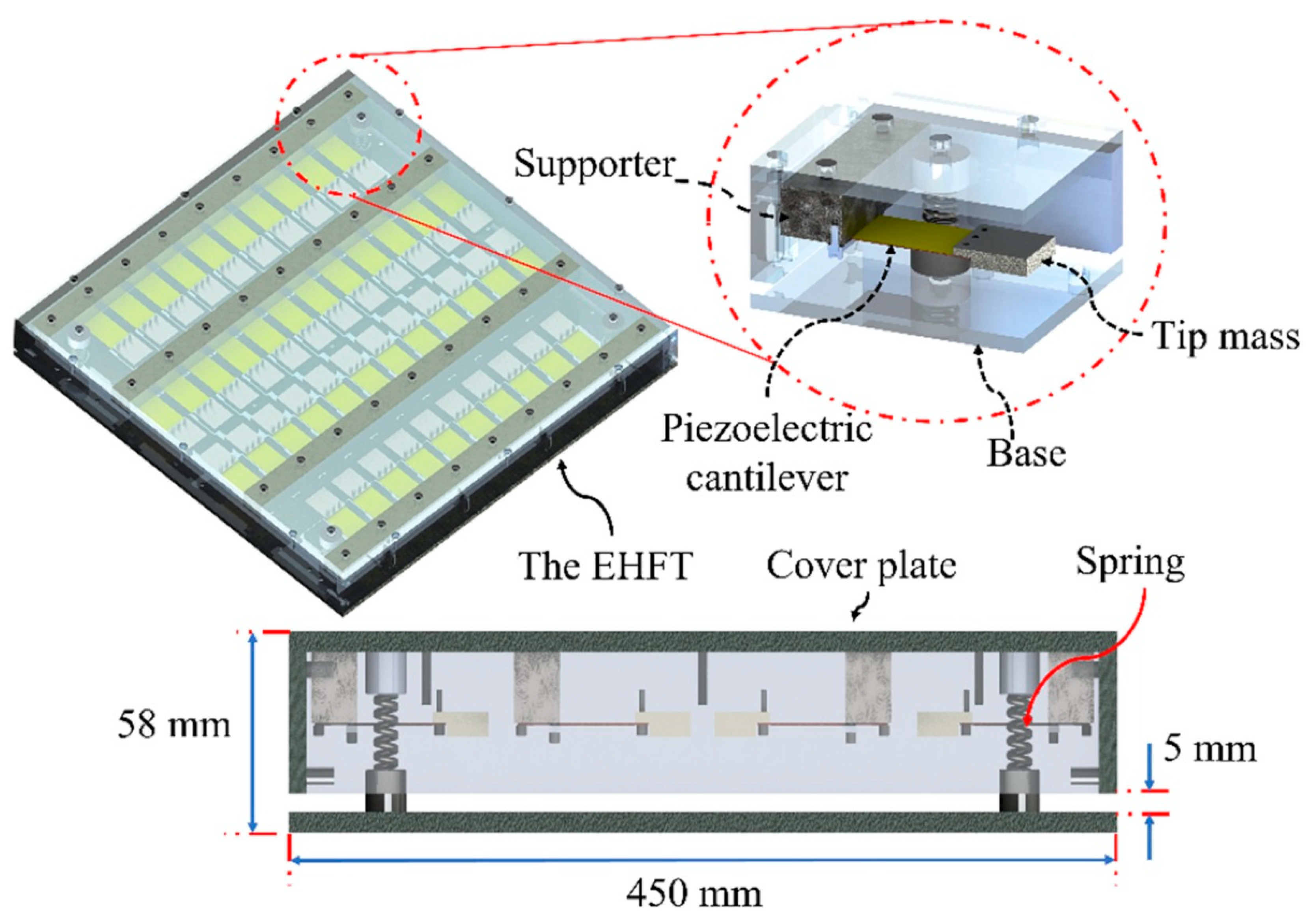
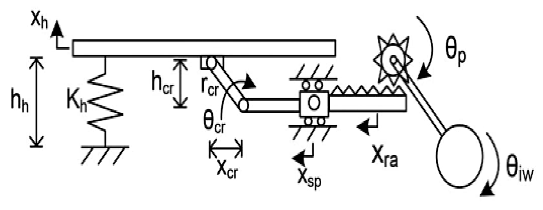
  36. Jintanawan, T.; Phanomchoeng, G.; Suwankawin, S.; Kreepoke, P.; Chetchatree, P.; U-viengchai, C. Design of Kinetic-Energy Harvesting Floors. Energies 2020, 13, 5419. [Google Scholar] [CrossRef]
  37. Yildiz, F. Low Power Energy Harvesting and Storage Techniques from Ambient Human Powered Energy Sources; University of Northern Iowa: Cedar Falls, IA, USA, 2008. [Google Scholar]
  38. Good, R.H.; Nelson, T.J. Classical Theory of Electric and Magnetic Fields; Academic Press: New York, NY, USA, 2013; ISBN 978-1-4832-7203-0. [Google Scholar]
  39. Turnbull, F.G.; Pauk, O. 14—Power Electronics—Rectifiers, Filters, and Power Supplies. In Reference Data for Engineers, 9th ed.; Middleton, W.M., Van Valkenburg, M.E., Eds.; Newnes: Woburn, MA, USA, 2002; ISBN 978-0-7506-7291-7. [Google Scholar]
  40. Yilmaz, M.; Tunkar, B.A.; Park, S.; Elrayes, K.; Mahmoud, M.A.E.; Abdel-Rahman, E.; Yavuz, M. High-Efficiency Passive Full Wave Rectification for Electromagnetic Harvesters. J. Appl. Phys. 2014, 116, 134902. [Google Scholar] [CrossRef]
  41. Zhang, W.; Lin, H.; Zhang, Y.; Jin, J. Modeling and Controlling Strategy of Four-Switch Buck-Boost Convertor with Smooth Mode Transitions. Open Electr. Electron. Eng. J. 2017, 11, 56–67. [Google Scholar] [CrossRef] [Green Version]
  42. Four-Switch Buck-Boost Converter in Buck or Boost Mode Delivers the Highest Efficiency—EDN. Available online: https://www.edn.com/four-switch-buck-boost-converter-in-buck-or-boost-mode-delivers-the-highest-efficiency/ (accessed on 7 September 2021).
  43. Bowick, C. RF Circuit Design, 2nd ed.; Newnes: Amsterdam, The Netherlands; Boston, MA, USA, 2007; ISBN 978-0-7506-8518-4. [Google Scholar]
  44. Silicon Labs Impedance Matching Network Architectures. Available online: https://www.silabs.com/documents/public/application-notes/an1275-imp-match-for-network-arch.pdf (accessed on 13 September 2021).
  45. Wang, Z.L.; Wang, A.C. On the Origin of Contact-Electrification. Mater. Today 2019, 30, 34–51. [Google Scholar] [CrossRef]
  46. Kim, Y.; Lee, J.; Park, S.; Park, C.; Park, C.; Choi, H.-J. Effect of the Relative Permittivity of Oxides on the Performance of Triboelectric Nanogenerators. RSC Adv. 2017, 7, 49368–49373. [Google Scholar] [CrossRef] [Green Version]
  47. Zhao, Z.; Zhou, L.; Li, S.; Liu, D.; Li, Y.; Gao, Y.; Liu, Y.; Dai, Y.; Wang, J.; Wang, Z.L. Selection Rules of Triboelectric Materials for Direct-Current Triboelectric Nanogenerator. Nat. Commun. 2021, 12, 4686. [Google Scholar] [CrossRef]
  48. Pan, S.; Zhang, Z. Fundamental Theories and Basic Principles of Triboelectric Effect: A Review. Friction 2019, 7, 2–17. [Google Scholar] [CrossRef]
  49. Sun, W.; Wang, N.; Li, J.; Xu, S.; Song, L.; Liu, Y.; Wang, D. Humidity-Resistant Triboelectric Nanogenerator and Its Applications in Wind Energy Harvesting and Self-Powered Cathodic Protection. Electrochim. Acta 2021, 391, 138994. [Google Scholar] [CrossRef]
  50. Sriphan, S.; Charoonsuk, T.; Maluangnont, T.; Vittayakorn, N. High-Performance Hybridized Composited-Based Piezoelectric and Triboelectric Nanogenerators Based on BaTiO3/PDMS Composite Film Modified with Ti0.8O2 Nanosheets and Silver Nanopowders Cofillers. ACS Appl. Energy Mater. 2019, 2, 3840–3850. [Google Scholar] [CrossRef]
  51. Niua, S.; Wang, Z.L. Theoretical systems of triboelectric nanogenerators. Nano Energy 2015, 14, 161–192. [Google Scholar] [CrossRef] [Green Version]
  52. Li, Y.; Zhao, Z.; Liu, L.; Zhou, L.; Liu, D.; Li, S.; Chen, S.; Dai, Y.; Wang, Z.L. Improved Output Performance of Triboelectric Nanogenerator by Fast Accumulation Process of Surface Charges. Adv. Energy Mater. 2021, 11, 2100050. [Google Scholar] [CrossRef]
  53. Hwang, S.J.; Jung, H.J.; Kim, J.H.; Ahn, J.H.; Song, D.; Song, Y.; Lee, H.L.; Moon, S.P.; Park, H.; Sung, T.H. Designing and Manufacturing a Piezoelectric Tile for Harvesting Energy from Footsteps. Curr. Appl. Phys. 2015, 15, 669–674. [Google Scholar] [CrossRef]
  54. He, M.; Wang, S.; Zhong, X.; Guan, M. Study of a Piezoelectric Energy Harvesting Floor Structure with Force Amplification Mechanism. Energies 2019, 12, 3516. [Google Scholar] [CrossRef] [Green Version]
  55. Yingyong, P.; Thainiramit, P.; Jayasvasti, S.; Thanach-Issarasak, N.; Isarakorn, D. Evaluation of Harvesting Energy from Pedestrians Using Piezoelectric Floor Tile Energy Harvester. Sens. Actuators A Phys. 2021, 331, 113035. [Google Scholar] [CrossRef]
  56. Duarte, F.; Ferreira, A.; Fael, P. Road Pavement Energy–Harvesting Device to Convert Vehicles’ Mechanical Energy into Electrical Energy. J. Energy Eng. 2018, 144, 04018003. [Google Scholar] [CrossRef]
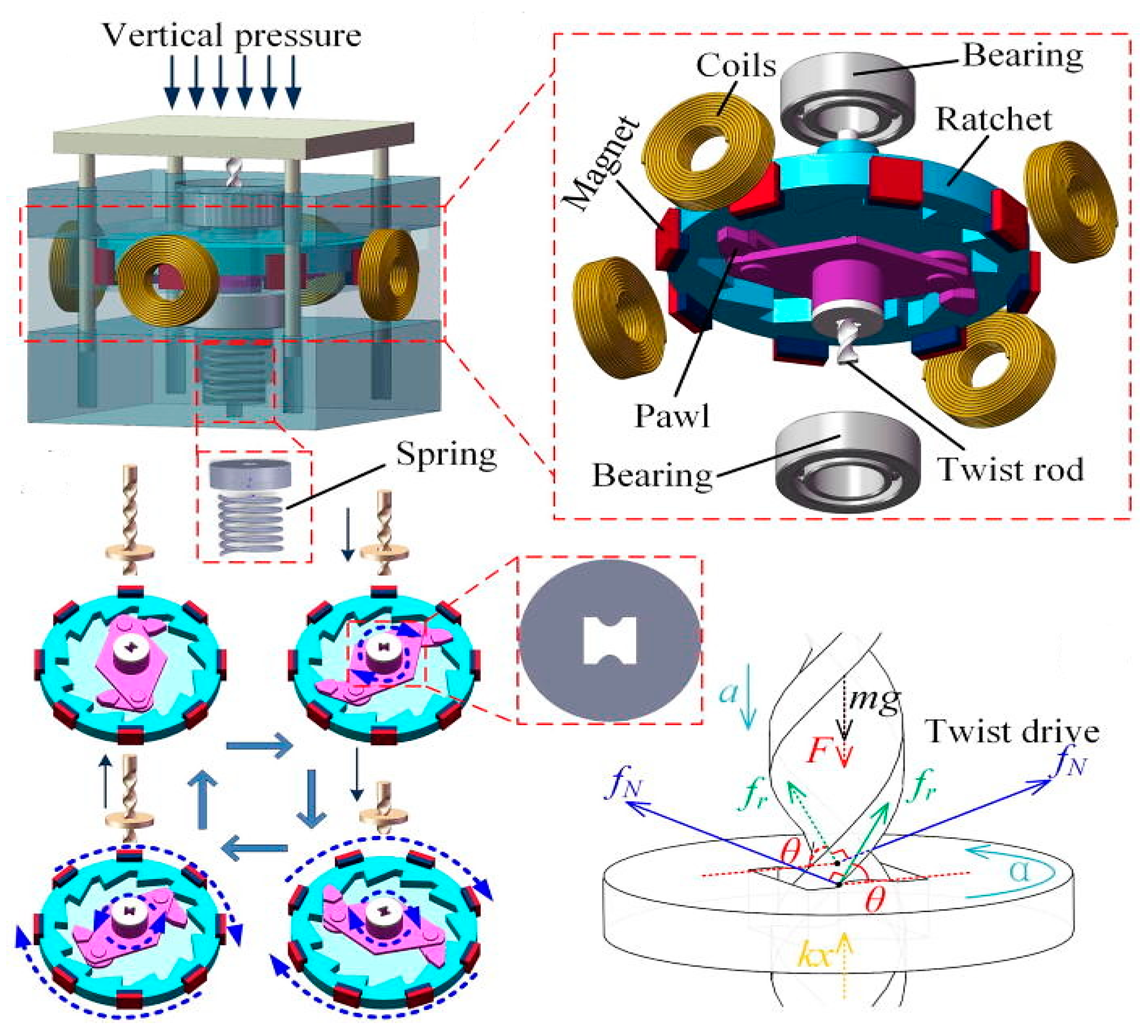
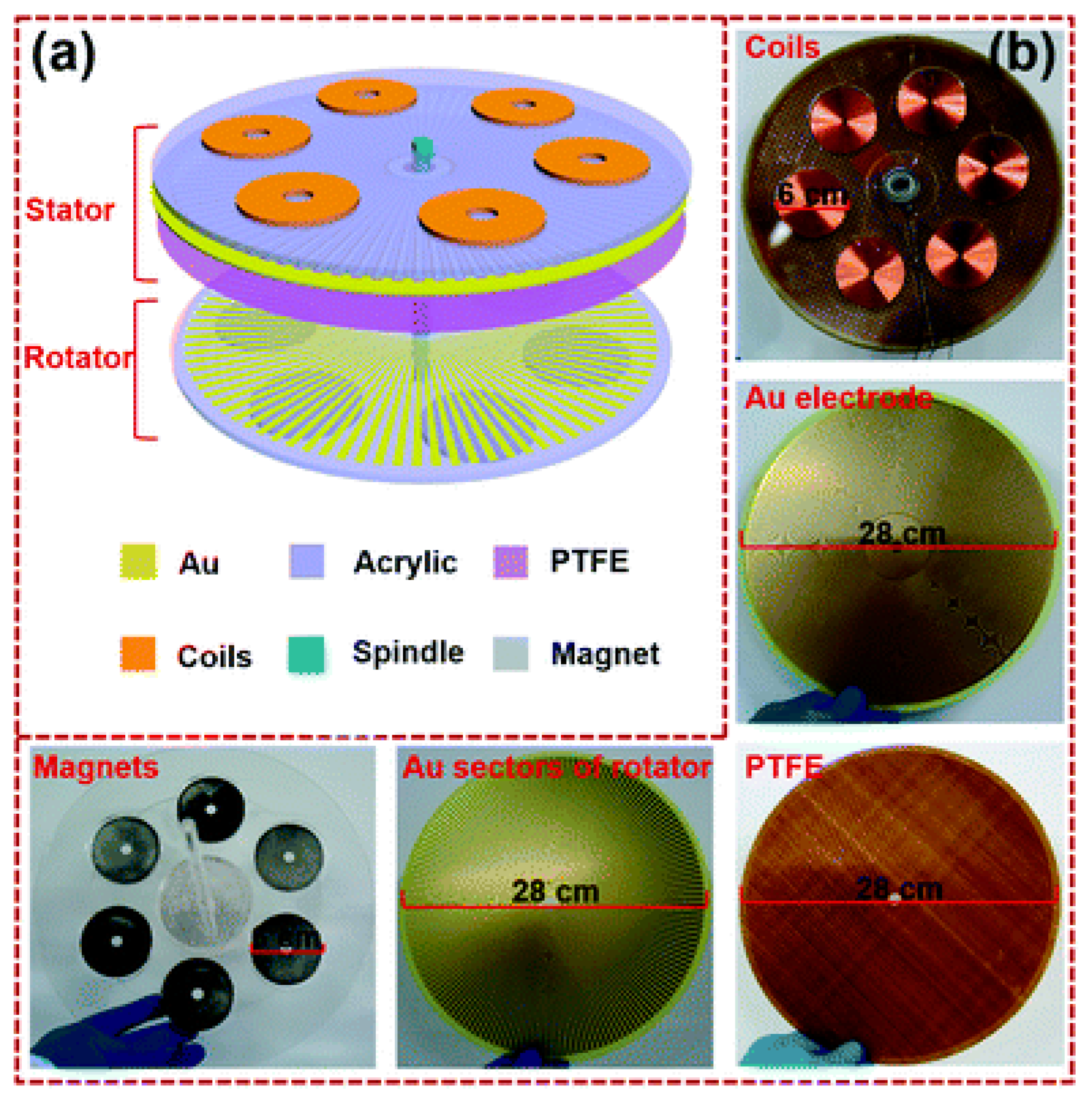
  57. Zhang, Y.; Luo, A.; Wang, Y.; Dai, X.; Lu, Y.; Wang, F. Rotational Electromagnetic Energy Harvester for Human Motion Application at Low Frequency. Appl. Phys. Lett. 2020, 116, 053902. [Google Scholar]
  58. He, C.; Zhu, W.; Chen, B.; Xu, L.; Jiang, T.; Han, C.; Gu, G.Q.; Li, D.; Wang, Z.L. Smart Floor with Integrated Triboelectric Nanogenerator As Energy Harvester and Motion Sensor. ACS Appl. Mater. Interfaces 2017, 9, 26126–26133. [Google Scholar] [CrossRef] [PubMed]
  59. Wang, Z.L.; Lin, L.; Chen, J.; Niu, S.; Zi, Y. Triboelectric Nanogenerators; Green Energy and Technology; Springer International Publishing: Cham, Switzerland, 2016; ISBN 978-3-319-40038-9. [Google Scholar]
  60. Barkas, D.A.; Psomopoulos, C.; Papageorgas, P.; Kalkanis, K.; Piromalis, D.; Mouratidis, A. Sustainable Energy Harvesting through Triboelectric Nano–Generators: A Review of Current Status and Applications. Energy Procedia 2019, 157, 999–1010. [Google Scholar] [CrossRef]
  61. Islam, E.; Abdullah, A.M.; Chowdhury, A.; Tasnim, F.; Martinez, M.; Olivares, C.; Lozano, K.; Uddin, M. Electromagnetic- Triboelectric-Hybrid Energy Tile for Biomechanical Green Energy Harvesting. Nano Energy 2020, 77, 105250. [Google Scholar] [CrossRef]
  62. Zhao, C.; Zhang, Q.; Zhang, W.; Du, X.; Zhang, Y.; Gong, S.; Ren, K.; Sun, Q.; Wang, Z.L. Hybrid Piezo/Triboelectric Nanogenerator for Highly Efficient and Stable Rotation Energy Harvesting. Nano Energy 2019, 57, 440–449. [Google Scholar] [CrossRef]
  63. Chen, Y.; Cheng, Y.; Jie, Y.; Cao, X.; Wang, N.; Wang, Z.L. Energy Harvesting and Wireless Power Transmission by a Hybridized Electromagnetic–Triboelectric Nanogenerator. Energy Environ. Sci. 2019, 12, 2678–2684. [Google Scholar] [CrossRef]
  64. Mallineni, S.S.K.; Dong, Y.; Behlow, H.; Rao, A.M.; Podila, R. A Wireless Triboelectric Nanogenerator. Adv. Energy Mater. 2018, 8, 1702736. [Google Scholar] [CrossRef] [Green Version]
  65. Energy Harvesting System Market by Technology, Component, Application- COVID-19 Impact Analysis. Available online: https://www.marketsandmarkets.com/Market-Reports/energy-harvesting-market-734.html (accessed on 25 August 2021).
  66. About Pavegen|How it All Started. Consultato 5 Settembre 2021. Available online: https://pavegen.com/ar/about/ (accessed on 1 June 2021).
  67. Energy-Harvesting Street Tiles Generate Power from Pavement Pounder—Scientific American. Available online: https://www.scientificamerican.com/article/pavement-pounders-at-paris-marathon-generate-power/ (accessed on 5 September 2021).
  68. PAVEGEN V3. Available online: https://www.wevolver.com/wevolver.staff/pavegen.v3 (accessed on 5 September 2021).
  69. Seow, Z.L.; Chen, S.; Khairudin, N. An Investigation into Energy Generating Tiles: Pavegen; APSC 261; UBC Social Ecological Economic Development Studies (SEEDS) Student Report; University of British Columbia: Vancouver, BC, Canada, 2012; pp. 1–20. [Google Scholar]
  70. Pavegen’s Power-Generating Floor Is Coming to Oxford Street|WIRED UK. Available online: https://www.wired.co.uk/article/pavegen-tile-power-generation-london (accessed on 5 September 2021).
  71. Energy Harvesting: Pavegen and the Rise of Kinetic Tile Tech. Available online: https://theswitch.co.uk/energy/guides/technology/energy-harvesting-tiles (accessed on 5 September 2021).
  72. Tech: Pavegen—The Technology behind the Tile|EG News. Available online: https://www.egi.co.uk/news/pavegens-the-technology-behind-the-tile/ (accessed on 10 September 2021).
  73. Webster, Craig, e Philip Tucker. Flooring System. U.S. Patent US20190048858A1, 14 February 2019. Available online: https://patents.google.com/patent/US20190048858A1/en?q=flooring+system&assignee=pavegen&oq=flooring+system+pavegen (accessed on 1 June 2021).
  74. Webster, Craig. Electrical Generator. World Intellectual Property Org. WO2017194937A1, 16 November 2017. Available online: https://patents.google.com/patent/WO2017194937A1/en?q=electrical+generator&assignee=pavegen&oq=electrical+generator+pavegen (accessed on 14 June 2021).
  75. Sustainable Dance Floor|Studio Roosegaarde. Available online: https://www.studioroosegaarde.net/project/sustainable-dance-floor (accessed on 14 September 2021).
  76. Cornelis, B.J.; Alijd, J.; Van Doorn, S.; Van Dongen, A.; Randag, A.; Jan Jansen, J.; Jacobus Hubertus Paulides, J.; Willem Jansen, E.A.; Lomonova, D.F.; Roosegaarde Bisschop. Vloer. NL1034439C1, 31 March 2009. Available online: https://patents.google.com/patent/NL1034439C1/nl (accessed on 2 September 2021).
  77. Sustainable Energy Floor Specifications. Available online: https://issuu.com/sustainabledanceclub/docs/sustainable_energy_floor_specifications (accessed on 9 September 2021).
  78. Home|Energy Floors. Available online: https://energy-floors.com/ (accessed on 5 September 2021).
  79. OTEM2000. Productos UFIPV. Available online: https://otem2000.wixsite.com/otem2000eng/hybrid-energyfloor-eng (accessed on 10 September 2021).
  80. OTEM2000. Productos IIPV. Available online: https://otem2000.wixsite.com/otem2000eng/solarfloor-eng (accessed on 10 September 2021).
  81. Pilarski, N.; OTEM2000. Solucions Innovadores per a Laprofitament Energètic de la Mobilitat. 2018. Available online: https://www.youtube.com/watch?v=QRmBkFdC6ro (accessed on 15 June 2021).
  82. Hernández, A. ORTI. Baldosa Pisable Generadora de Electricidad. World Intellectual Property Org. WO2014167147A1, 16 October 2014. Available online: https://patents.google.com/patent/WO2014167147A1/es?q=baldosa+pisable&oq=baldosa+pisable (accessed on 15 June 2021).
  83. Calcagni, A. Floor Tile. World Intellectual Property Org. WO2018065854A1, 12 April 2018. Available online: https://patents.google.com/patent/WO2018065854A1/fr?inventor=alessio+calcagni&oq=alessio+calcagni (accessed on 11 June 2021).
  84. Equinvest. Rassegna stampa Veranu. 2017. Available online: http://www.veranu.eu/files/RS2017_veranu_010203.pdf (accessed on 10 June 2021).
  85. Company Profile Veranu, s.d. Available online: http://www.veranu.eu/files/Company_Profile_Veranu_EN.pdf (accessed on 10 September 2021).
  86. Veranu, the Startup That Generates Energy Step by Step. Available online: https://blog.treedom.net/en/blog/post/veranu-the-startup-that-generates-energy-step-by-step-1919 (accessed on 15 September 2021).
  87. Duarte, F.; Casimiro, F.; Azevedo, E.D. Pavement Module for Generating Electric Energy from the Movement of People and Vehicles. World Int. Property Org. WO2011145057A2, 24 November 2011. Available online: https://patents.google.com/patent/WO2011145057A2/zh (accessed on 10 June 2021).
  88. Duarte, F.; Casimiro, F.; Correia, D.; Mendes, R.; Ferreira, A. A New Pavement Energy Harvest System. In Proceedings of the 2013 International Renewable and Sustainable Energy Conference (IRSEC), Ouarzazate, Morocco, 7–9 March 2013; pp. 408–413. [Google Scholar]
  89. Bashir, M.; Rajendran, P. A Review on Electroactive Polymers Development for Aerospace Applications. J. Intell. Mater. Syst. Struct. 2018, 29, 3681–3695. [Google Scholar] [CrossRef]
  90. Moretti, G.; Rosset, S.; Vertechy, R.; Anderson, I.; Fontana, M. A Review of Dielectric Elastomer Generator Systems. Adv. Intell. Syst. 2020, 2, 2000125. [Google Scholar] [CrossRef]
  91. Zhou, J.; Jiang, L.; Khayat, R. Investigation on the Performance of a Viscoelastic Dielectric Elastomer Membrane Generator. Soft Matter 2015, 11, 2983–2992. [Google Scholar] [CrossRef]
  92. McKay, T.G.; Rosset, S.; Anderson, I.A.; Shea, H. An Electroactive Polymer Energy Harvester for Wireless Sensor Networks. J. Phys. 2013, 476, 012117. [Google Scholar]
  93. Chiba, S.; Waki, M. Innovative Power Generator Using Dielectric Elastomers (Creating the Foundations of an Environmentally Sustainable Society). Sustain. Chem. Pharm. 2020, 15, 100205. [Google Scholar] [CrossRef]
  94. Redmond, E. Flooring System and Floor Tile. U.S. Patent US20130154441A1; Filed 23 September 2012, 23 June 2013. Available online: https://patents.google.com/patent/US20130154441/en?oq=powerleap (accessed on 10 June 2021).
  95. Powerleap. Available online: https://www.mascontext.com/tag/powerleap/ (accessed on 9 September 2021).
  96. The Power Beneath Your Feet, Sci-Tech—Trends in Japan. Available online: https://web-japan.org/trends/09_sci-tech/sci100107.html (accessed on 9 September 2021).
  97. Hayamizu, K. Electric Apparatus Provided with Power Generating Function. U.S. Patent US8686620B2, 1 April 2014. Available online: https://patents.google.com/patent/US8686620B2/en?oq=US+8%2c686%2c620+B2 (accessed on 21 June 2021).
Figure 1. Example of piezoelectric tile.
Energies 15 00432 g001
Figure 2. Piezoelectric effect in quartz.
Energies 15 00432 g002
Figure 3. Schematic representation of single-layer (a) and multi-layers piezoelectric generators (b).
Energies 15 00432 g003
Figure 4. Electrical model of a piezoelectric transducer.
Energies 15 00432 g004
Figure 5. Typical resonant characteristic of a piezoelectric transducer.
Energies 15 00432 g005
Figure 6. Example of a power management system of the EM harvester [36].
Energies 15 00432 g006
Figure 7. Power efficiency of full-wave rectifiers as a function of input voltage Vin (left); full-wave rectifier constituted by two PMOS (P-M1, P-M2) and two NMOS (N-M1, N-M2) (right) [40].
Energies 15 00432 g007
Figure 8. Schematic of a two-switch buck-boost converter: MOSFETs Q1 and Q2 share a gate-control signal and switch on and off at the same time in buck-boost mode.
Energies 15 00432 g008
Figure 9. Electron-cloud-potential-well model to explain triboelectrification between two materials [45].
Energies 15 00432 g009
Figure 10. Electrification scale for triboelectric series design [35].
Energies 15 00432 g010
Figure 11. The four fundamental modes of TENGs: vertical contact mode, lateral sliding mode, single electrode mode, and free-standing triboelectric layer mode [48].
Energies 15 00432 g011
Figure 12. Triboelectric pairs: dielectric-to-dielectric and conductor-to-dielectric contact [51].
Energies 15 00432 g012
Figure 13. Working mechanism of self-charge excitation TENG during the periodic contact-separation process [52].
Energies 15 00432 g013
Figure 14. Example of Frequency-up converter [35].
Energies 15 00432 g014
Figure 15. Graphic representation of the piezoelectric tile (a) and a close-up of the piezoelectric modules installed on the center plate (b) [53].
Energies 15 00432 g015
Figure 16. Schematic of the “squeezing structure”: front view (a) and three-dimensional rendering (b) [54].
Energies 15 00432 g016
Figure 17. 3D and cross-section views of the piezoelectric EHFT proposed in [42].
Energies 15 00432 g017
Figure 18. Block diagram of electromagnetic harvesting system [36].
Energies 15 00432 g018
Figure 19. Two different mechanical configurations applied to electromagnetic smart tiles: rack-pinion model (a), lead-screw model (b) [36].
Energies 15 00432 g019
Figure 20. Lever system [43].
Energies 15 00432 g020
Figure 21. Crank-to-slider mechanism coupled to a rack-and-pinion system and an IW [56].
Energies 15 00432 g021
Figure 22. 3D model of the rotational electromagnetic harvester installed in the smart tile [57].
Energies 15 00432 g022
Figure 23. Output characteristic of the smart tile [57].
Energies 15 00432 g023
Figure 24. Operating modalities of the SF-TENG, Mode I (a) and Mode II (b) [58].
Energies 15 00432 g024
Figure 25. Layer with magnets and the electrode for the triboelectric generator (a); layer with copper coils (b); layers that make the tile (c); rectifying circuits (d) [61].
Energies 15 00432 g025
Figure 26. Operative phases of the triboelectric and electromagnetic generators [61]; working mechanism of the triboelectric generator (i) Initial stage, (ii) Contact stage, (iii), (iv) Separation stage, (v) final stage (a); working mechanism of the electromagnetic generator (i) Initial stage, (ii) Contact stage (b).
Energies 15 00432 g026
Figure 27. Diagram of the hybridized nanogenerator: coils are on the stator, magnets on the rotator (a); photographs of the hybridized nanogenerator (b) [63].
Energies 15 00432 g027
Figure 28. Wireless power transmission based on W-TENG (Wireless Triboelectric Nanogenerator). Equivalent-circuit model for the emission section (a), photographs of the transmitter (b), output current of 130.6 mA by the hybridized nanogenerator through two DC transformers with 5 V output (c), transmission distance of the WPT system: 40 cm (d-i) and 60 cm (d-ii) with a hand besides the receiver. Mobile phone charged by the WPT system with a distance 100 cm away from the transmitter (e). The output voltage through a voltage booster at a distance of 80 cm (f) [63].
Energies 15 00432 g028
Figure 29. Cross-sectional view of the W-TENG and working mechanism’s schematic: pressure (a) and release (b) phases of the top electrode (Teflon); dependence of W-TENG’s output voltage on thickness of the gPLA bottom electrode; here 2L, 4L, 6L represent two, four, and six layers of printed gPLA electrodes whose thicknesses are ≈1, 2, 3 mm, respectively (ce) [64].
Energies 15 00432 g029
Figure 30. V3® version of Pavegen’s tile [68]; top view (a), side view (b).
Energies 15 00432 g030
Figure 31. Detail of installation of the tiles.
Energies 15 00432 g031
Figure 32. Sustainable Dance Floor® (a), and a cross-section of the harvester (b) [75].
Energies 15 00432 g032
Figure 33. Working principle of the Sustainable Energy Floor® [77].
Energies 15 00432 g033
Figure 34. HEFs based on photovoltaic panels and EnergyFloors electromechanical technology [79].
Energies 15 00432 g034
Figure 35. Different OTEM2000’s products: EnergyFloors® solution to recover energy from the person’s footsteps (a), example of HEF® tile (b); IEPAS® (c) and EVELRED® real applications to recover energy from car transit (d) [82].
Energies 15 00432 g035
Figure 36. Veranu piezoelectric tile [86].
Energies 15 00432 g036
Figure 37. EAP generator proposed in [92].
Energies 15 00432 g037
Figure 38. SoundPower®’s tiles [96].
Energies 15 00432 g038
Table 1. Comparison between single-layer and multi-layer piezoelectric generators.
Single-Layer Piezoelectric GeneratorMulti-Layer Piezoelectric Generator
Higher Output Voltage (+)Lower Output Voltage (−)
Lower Output Current (−)Higher Output Current (+)
Higher Output Impedance (−)Lower Output Impedance (+)
Lower Inner Capacitance (−)Higher Inner Capacitance (−)
Higher Polarization (−)Lower Polarization Voltage (−)
Table 2. Surface charge density after triboelectrification for different materials [48].
Material PairCharge Density (C/m2)
Chromium-Chromium2.02 × 10–8
Chromium-Steel3.37 × 10–8
Chromium-Gold6.73 × 10–8
Metal-SiO2 (quartz)~10–5
Metal-NaCl5.0 × 10–4
Metal-Nylon~10–3
Metal-PTFE~10–4–10–3
Metal-Polyimide3.0 × 10–3
Table 3. Macroscopic differences between piezoelectric and triboelectric harvesting solutions [22].
PENGTENG
Materials and Fabrication
  • Commercialised technique
  • Compatible with MEMS process
  • Relative complex and expensive process
  • Ceramics are fragile
  • Wide options of materials
  • Relative cheap for most of the materials
  • Easy to fabricate
Power density
  • High power density
  • Affected by operation frequency
  • Relative low power density, but highly tunable with surface texturing and charge implementation, etc.
  • Multiple operation modes
Sensing (sensitivity, sensing range, response time)
  • Suitable for high dynamic sensing
  • Fast response
  • Poor static sensing
  • Wide sensing range (depend on o materials and design)
  • Good dynamic sensing
  • Fast response
  • Poor static sensing
Scalability
  • Suitable for miniaturization
  • Expensive and fragile for large size applications
  • Suitable for large-area applications
  • Low output after miniaturization
Stability
  • Good electrical stability
  • Poor mechanical stability
  • Sensitive to environmental fluctuations, i.e., humidity.
  • Good mechanical stability (depends on material and design)
Biocompatibility
  • Polymer and lead-free materials are biocompatible
  • Lead-based ceramics need encapsulation
  • Many polymers are biocompatible
  • Able to apply the biocompatible materials to fabricate TENG directly
Table 4. Summary and performance comparison of presented smart floor devices in terms of transduction mechanism, main features, size and produced output power.
Device—CompanyUses and FeaturesDimensionOutput Power
V3® by Pavegen
[68,70]
  • In train stations, airports, shopping centres, etc.
  • Each tile has a wireless API that transmits real-time data of the movement.
  • Wireless trasmission system.
  • It has a football tracker system.
  • Electromagnetic harvesting system (V3).
50 cm on each side5 W/step
Sustanaible Dance Floor® by Studio Roosegaarde [75]
  • Used in dance clubs.
  • Save 30% total energy of the club at the party.
  • Electromechanical harvesting system.
65 cm × 65 cm × 30 cm25 W/module
Sustainable Energy Floor® by Energy Floors [77]
  • Used in train station pavements, airports, shopping malls, etc.
  • Customizing modules.
50 cm × 50 cm × 10 cm2 ÷ 20 J/step
Smart Energy Floor® by Energy Floors [78]
  • Three models for different applications.
  • Adapt for education but expensive.
  • Electromechanical system.
60 cm × 60 cm35 W with a 10 mm airgap
Hybrid Energy Tile® by OTEM2000 [81]
  • Combine photovoltaic technology with other energy sources.
  • Solar panels contain Copper Indium Selenide (CIS), maximizing efficiency.
  • Hybrid and Customizable system.
  • Wireless transmitting system.
50 cm × 50 cm;
75 cm × 75 cm;
100 cm × 100 cm
Not specified
Smart Energy Floor by Veranu® [83]
  • Simple maintenance.
  • Ecological materials and low cost.
  • Piezoelectric system.
  • Not for large scale power production.
30 cm × 30 cm × 4 cm2 W/step
Waynergy tiles by Waydip Co. [87]
  • Out of production.
  • Electromechanical system.
  • Adapt to harvest energy from vehicles.
40 cm × 40 cm10 W
Dielectric Elastomer Generator [92]
  • Low cost and small dimensions.
  • Problem with current leakage.
  • Commercial devices not available.
  • Dielectric elastomer system.
11 mm × 11 mm × 9 mm (11 mm is the diameter)300 µW @ 0.5Hz
Powerleap tiles
[94,95]
  • Out of production.
  • Piezoelectric system.
  • Data wireless transmission of direction, velocity, time, weight, mass, speed of the users’ motion.
24″ × 24″0.5 mW/step
Power Generating Floor™ by SoundPower [96,97]
  • Piezoelectric system.
  • For feeding lighting systems.
50 cm × 50 cm0.1 W/step
Publisher’s Note: MDPI stays neutral with regard to jurisdictional claims in published maps and institutional affiliations.

