
Overview of Research Status of DC Bias and Its Suppression in Power Transformers
1
School of Electrical Engineering, Shandong University, Jinan 250061, China
2
Electric Power Research Institute of State Grid Henan Electric Power Company, Zhengzhou 450052, China
*
Author to whom correspondence should be addressed.
Energies 2022, 15(23), 8842; https://doi.org/10.3390/en15238842
Submission received: 26 October 2022
/
Revised: 15 November 2022
/
Accepted: 18 November 2022
/
Published: 23 November 2022
(This article belongs to the Special Issue Advanced Research of High Voltage Insulation)
Abstract
:In this article, the sources of DC bias and its effects on power transformers are first summarized. Secondly, the article classifies and summarizes the current DC bias calculation problems of power transformers, and puts forward some interesting viewpoints on the research logic of related calculations. The current processing methods of DC bias effect are classified and discussed, their advantages and disadvantages are compared, and the logic flow of DC bias effect processing is proposed. Finally, the current research on DC bias voltage of power transformers is summarized, and the progress and deficiencies of current research are pointed out, which has certain reference value for future research on DC bias voltage and its suppression.
1. Introduction
In the modern power grid, the construction scale of the direct current (DC) transmission system is gradually increasing, and the application field of power electronic equipment is becoming wider and wider, which leads to the DC bias phenomenon of the power transformer becoming more and more frequent. DC bias is an abnormal working state of the transformer, which refers to the DC component in the excitation current, which leads to half-wave saturation of the transformer, known as the transformer bias phenomenon, which is one of the main reasons for asymmetric operation of the transformer and surrounding power systems [1]. Its working principle can be illustrated in Figure 1. In Figure 1a the solid line represents the magnetic flux curve without DC bias, and the dotted line represents the magnetic flux curve under DC bias. Figure 1b shows the initial magnetization curve. In Figure 1c, the solid line represents the excitation current waveform in the winding without DC bias, and the dotted line represents the excitation current waveform in the winding under DC bias. DC bias is generated from the following aspects:
- (1)
- The influence of solar “magnetic storm”. The change in geomagnetic field induces potential gradient on the earth’s surface, and when this low-frequency occurs for a certain duration the electric field acts on the power transformer with neutral grounding of the transmission system. The surface potential gradient induces geomagnetic-induced current in its winding, with frequency between 0.001–1 Hz, which can be approximately regarded as DC compared with the 50 Hz alternating current (AC) system [2].
- (2)
- Parallel operation of DC transmission line and AC transmission line. The surface current generates a DC component in the excitation current of the AC transformer through the grounding neutral point of the AC transformer [3].
- (3)
- There are loads with asymmetric voltage current relationship curve in the AC network. Loads with asymmetric voltage current relationship curves, such as phase-controlled AC loads, phase-controlled rectifiers, and line commutation inverters, can generate DC components [4,5,6]. DC bias occurs in AC transformers under the above conditions. The harm of DC magnetic bias roughly includes the following aspects:
- (1)
- DC magnetic flux causes serious magnetic saturation of the transformer core every half cycle, and the excitation current is highly distorted, resulting in a large number of harmonics [7,8]. The Gaopo–Zhaoqing DC transmission line used to operate in the single pole grounding loop mode. The DC current at the neutral point of the main transformer at the end of the line reached 34.5 A, and the total distortion rate of harmonic voltage reached 2.1% [9]. When DC is biased, even harmonics appear in the excitation current, and the transformer becomes an active harmonic voltage source, which poses a great threat to the capacitor bank. When the single-pole ground loop operation occurred in the San–Guangzhou DC transmission system, the 500 kV Huizhou substation of Guangdong Power Grid monitored that the effective value of the fourth harmonic current of the second and third groups of capacitors on the low-voltage side of the main transformer was close to one third of the rated current, reaching 200 A. Due to the serious harmonic current exceeding the standard, the second and third groups of capacitors experienced five explosion accidents.
- (2)
- The serious magnetic saturation of DC bias on the transformer makes the magnetic flux, closed in the iron core, leave the iron core under normal conditions, which increases the vibration and loss of the metal structural parts of the transformer, leading to local overheating, damage to the insulation, damage to the transformer or reduction in the service life of the transformer [10]. During the commissioning of Longquan–Zhengping 500 kV DC transmission project, the DC current at the neutral point of two groups of 500 kV main transformers reached 12.8 A, and the noise was as high as 91.4 dB [9]. When DC bias occurs, the excitation current increases significantly, resulting in an increase in reactive power loss. This reduces the system voltage, causing the overload operation of reactive power compensation equipment, and seriously threatening the safe and reliable operation of the system. Scholars from Tokyo Electric Power Company of Japan and Toshiba Corporation conducted joint experimental research. Based on the experimental analysis of small model transformers and large model transformers (about 1/3 to 1/2 of the size of physical transformers), combined with the structural characteristics of transformers, it was pointed out that the core pull plate of the core transformer and the support plate of the shell transformer core were the key overheating parts under DC bias, respectively, and the corresponding relationship between the temperature rise of these components and the magnetic field strength was given. Reference [11] analyzed the changes of core loss, winding loss, core clip loss and transformer temperature rise of core-type transformers, of different grades and capacities, through experiments and simulations, and calculated 735 kV and 100 MV through two-dimensional finite element analysis. In regard to transformer core clip eddy current loss and its temperature rise, reference [12] simulated and calculated the losses of transformer core, tank wall and T-beam under the action of geomagnetic induced current (GIC) by means of two-dimensional finite element analysis.
- (3)
- Relay protection system failure. The previous research on the impact of other equipment in the power grid mainly focused on the transformer itself, and the impact on other equipment in the power grid is often ignored, but the harmonic generated by DC bias seriously impacts other equipment in the power grid, particularly current transformers (Tas), capacitor banks and relay protection equipment. When DC bias occurs in the transformer, the current waveform is seriously distorted, and the zero sequence sub-harmonic leads to faulty operation of zero sequence protection. Under the operation of the unipolar earth return line, the DC current of some substations of China’s Tianzhong DC transmission project reached more than 10 A. Under the single pole commissioning of Xizhe DC transmission project, the three substations with DC current greater than 20 A at the neutral point of the transformer and five substations with DC current greater than 10 A, could cause great harm to the normal operation of the power grid [13,14]. The main factors for the error of electromagnetic TA are the nonlinear excitation characteristics and saturation degree of the iron core. Reference [15] took 0.1-level TA 04-5 A/5 mA, commonly used in metering instruments, as an example, and used experimental data to study and analyze the influence of DC bias on the transfer characteristics of TA. DC bias caused the ratio of TA for metering to become negative. The direction changed, the angular difference changed to the positive direction, and this effect increased with the increase of the DC bias current. Reference [16] designed an AC–DC hybrid experimental method to simulate the real DC bias phenomenon, and analyzed the influence of DC bias on the error of TA for metrology through experimental data. The results showed that the DC bias did not change the saturation characteristics of the iron core. With the increase of the DC bias, the overall ratio difference shifted to the negative direction, the angular difference shifted to the positive direction, the harmonic components on the secondary side of TA increased, and there was an even number. The increase in sub-harmonic components was particularly pronounced. In the state of DC bias, the compensation capacitor bank might have harmonic amplification or even resonance, thus, endangering the safe operation of the capacitor bank. In reference [17], under the DC bias state, based on the Jiles–Atherton (J–A) theoretical model, the DC bias model of the transformer was established by using MATLAB. The research results showed that the harmonics increased approximately linearly with the increase of DC current, and the fourth harmonic amplification phenomenon occurred between capacitor banks. The ratio of the fourth harmonic to the fundamental wave exceeded 30%, which was far greater than the second harmonic, third harmonic and fifth harmonic. At present, the research on the influence of DC bias on relay protection mainly focuses on the influence of additional effects caused by transformer DC bias on relay protection. Reference [8] pointed out that, due to the harmonics caused by the DC bias of the transformer, the neutral point zero-sequence voltage protection, the overcurrent protection of the capacitor and the overvoltage protection malfunctioned, and the DC bias would cause the transformer core to heat up and cause gas protection action. The surge of excitation would cause the transformer differential protection to malfunction. Research in [18] showed that DC bias might accelerate TA saturation, and the time difference method criterion to prevent TA saturation caused by external faults would be tested. DC bias-induced partial transient saturation of TA might cause malfunction of the differential protection of the transformer.
It is of great significance to study the DC bias problem of transformers to explain and suppress the phenomenon of asymmetric operation of power equipment. This paper gives a comprehensive description of the phenomenon and research methods of DC bias, cites the mainstream analysis methods of DC bias analysis, and explains and compares the above analysis methods. At the same time, the current mainstream methods of transformer DC bias suppression are summarized and classified, and the advantages and disadvantages of various methods, and their applicable scenarios, are compared.
2. Research Status of the Generation Mechanism of DC Bias
2.1. Research on Transformer DC Bias Phenomenon Caused by Ground Current in HVDC Projects
The research on the distribution mechanism of the ground current of the DC transmission project in the AC power grid can be divided into two categories: to establish a calculation model of the DC current distribution of the AC power grid, including the complete above-ground AC power transmission network and various underground grounding grids; to focus on researching the influencing factors of the surface potential distribution near the ground electrode, and the DC current in the transformer, solved by using the surface potential. Although the current in the loop is due to the distortion of the surface potential, the causes of the distortion of the surface potential are different, which leads to the difference between the two simulations [19,20].
2.1.1. Research on Surface Potential near Grounding Electrode
When the DC system operates with the ground as the loop in unipolar operation, the fundamental cause of DC magnetic bias in surrounding substations is the distortion of the ground potential caused by the grounding current. When DC magnetic bias occurs, the DC current in the earth produces potential difference on the ground, and the DC current flows from the neutral point of one transformer to the neutral point of another transformer, forming a loop through overhead lines, as shown in Figure 2.
At this time, if there are two interconnected grounding substations, A and B, within a certain range from the grounding electrode, the ground potentials of substations A and B rise to VPA and VPB. When VPA ≠ VPB, there is a certain potential difference ΔU between stations A and B. At this time, due to the existence of line connection between the substations, ΔU forms a DC path through the grounding resistance RG of the two substations, the series resistance R0 of the neutral point, the DC resistance RW of the transformer winding, and the DC resistance RL of the transmission line, and forms a DC current I1 at the neutral point of the substation, as shown in Figure 3.
Therefore, the flow of DC current between multiple substations can be regarded as a multi-terminal network with sources. With the ground potential VP of the grounding electrode of each substation as the input source, the multi-terminal network Y is formed by the grounding resistance RG of the substation, the series resistance R0 of the neutral point, the DC resistance RW of the transformer winding, and the DC resistance RL of the transmission line. Among them, the surface potential VP is an important parameter required in the calculation of DC distribution. When calculating the DC bias current, first calculate the surface potential distribution VP, and then take the multi-terminal network Y as the research object to analyze the DC path model of the power grid.
Scholars conducted an in-depth analysis of the influencing factors of the ground potential near the ground pole. According to the grounding theory, the ground potential distortion caused by the grounding current can be attributed to the solution of the Green’s function of the point power supply in the soil medium [21,22]. Considering the complexity of the earth model, the soil model is generally considered to be horizontal multi-layer and vertical multi-layer. Due to the complexity of multi-layer soil, its Green’s function is complex and difficult to derive manually. To this end, Zhao proposed a recursive algorithm for calculating the current field of point current sources with any layered horizontal or vertical soil structure, and used the recursive method to obtain the process of the current field in the horizontal or vertical multi-layer soil [23]. Guo proposed a recursive method for horizontally stratified soil by establishing a reasonable Green’s function structure, and realized computer derivation, avoiding the tediousness of manual derivation [24]. Pan gave a general theoretical expression of the Green’s function of any layer in the whole space, according to the separation variable method and the boundary conditions of the layered soil in the whole space. By comparing with CDGES, they verified the reliability of the method and deduced the Green’s function of vertical layered soil. The expression of the function expands the application range of the method [23,24,25]. For large-scale soils, rivers, mountains, oceans, etc., it is impossible to simulate through horizontal or vertical layers. Therefore, the finite element method was used in [26] to analyze the surface potential near the grounding electrode when the DC transmission unipolar was operating. The distribution characteristics, and the simplified mathematical model of earth resistivity facilitated qualitative analysis of the influence of topography, earth resistivity of each layer, ground electrode design and the interaction of multiple ground electrodes on the surface potential distribution. Reference [27] focused on analyzing the influence of soil structure on the DC current distribution at the neutral point of the transformer, and believed that “the horizontal uniformity of the upper soil has a greater impact on the ground potential distribution”, and selection of a substation site should consider the substation grounding grid and DC grounding. Coupling channels between poles have regions of low resistivity (such as lakes) or regions of high resistivity (such as Rocky Mountains). Academicians Zheng, Li and Liu focused their research on the composite soil model. According to the physical meaning of the mirror method, they deduced the calculation formula for the surface potential of the grounded pole, and compared the differences in the surface potential distribution under the composite soil model. It was emphasized that the surface potential and the topology of the AC power grid were important factors affecting the distribution of the DC current flowing through the neutral point of the transformer [28,29,30,31,32]. Li used the positive power function transformation in the conformal transformation to convert the three-dimensional space into a two-dimensional space, put forward the concept of the extended mirror method, and derived the functional expression of the surface potential distribution in the peninsula geological environment [33]. Dr. Ren studied the feasibility of humus simplification of large-scale multi-layered geological structures and the influence of AC transmission lines and substation grounding grids on the distribution of DC ground potential [34], and obtained the equivalent solution for the shunting of DC incoming ground current through the AC grid circuit. The calculation formula of DC ground potential was deduced.
2.1.2. Research on DC Current Calculation Model of AC Power Network
In order to establish an accurate DC current distribution model, scholars carried out a lot of research. Zhu took the AC/DC system of China Southern Power Grid in 2005 as the research object, carried out the equivalent simplification of the system, and used EMTDC to simulate and calculate the “equivalently simplified earth grid model”. The suppression effect of the line series capacitance and the neutral point series capacitance grounding was analyzed [35]. Ma applied the black box theory to transform the complex earth current field calculation into a circuit calculation, and evolved the electric field–circuit alternation problem into a pure circuit problem, thereby simplifying the analysis and forming a research conclusion: “The DC ground grid and the AC power grid are formed by the ground electrode. A certain strength coupling is the main way for the DC transmission ground current to affect the AC power grid” [36]. Cao used the field circuit coupling method and the resistance network analysis method to calculate and compare the DC current flowing into the transformer neutral point. The difference between the two methods is very small, but the resistance network analysis method is simpler [37]. Based on the idea of field-circuit coupling, Zhang regarded the entire DC grounding electrode, AC grounding grid and AC transmission line as a complex system composed of a resistance network located on the ground and a multi-conductor current field located underground, and established an analysis of the DC Numerical method for DC current distribution of the AC system during ground operation, so as to predict the DC current distribution of the AC system, and use the predictive model to analyze its suppression measures. Through the analysis, the factors affecting the current flowing through the line were: the ground potential difference at both ends of the line (determined by the distance from the DC pole, the direction of the line, and the length of the line), the equivalent impedance of the earth at both ends of the line (determined by the geological conditions of the earth, and the grounding of the substation network conditions), the equivalent DC resistance of the line (determined by the length of the line, the number of lines, and the parameters of the wire) [38,39,40,41]. Based on the field–circuit coupling model, Pan refined the evaluation standard of DC current distribution to the total amount of DC current in different directions on transformer windings of different voltage levels and different forms. The influence of the 110 kV neutral point grounding method, tower-lightning conductor system, and mutual resistance between substations, on the distribution of DC current in the power grid was assessed. The calculation software of the DC current distribution in the AC grid was developed as a result of the study [42]. A network algorithm for grounding electrode coupling analysis was proposed in [36]. Assuming that the power system is composed of m bus nodes, n power plants, k point-to-point DC transmission lines, and l grounding transformer, and assuming that the DC potential at infinity is 0, the following matrix equation is satisfied when the system’s k DC lines are operating at the same time on a single pole:
In Formula (1), Gaa is (m + n) of AC power grid × (m + n) order DC conductance matrix; Gad is composed of mutual conductance of AC network and DC network (m + n) × 2k order conductivity matrix; Gdd is the 2k × 2k conductivity matrix composed of DC grounding electrode characteristics; Ua is the (m + n) dimension DC voltage vector of AC power grid bus and AC grounding electrode; Ud is the 2k dimension DC voltage vector of DC grounding electrode bus; Id is the 2k dimensional earth current vector injected into the grounding electrode during the operation of DC monopole earth loop.
Given G and I, the DC voltage U of AC bus can be obtained:
Then the DC component Il of the transformer neutral point is:
In Formula (3), Gl is the conductance of transformer winding; UWI is the DC voltage of transformer bus; UNI is the DC voltage at the connection between the transformer neutral point and the grounding electrode.
2.2. Research on Transformer DC Bias Caused by GIC
During a magnetic storm, the time-varying geomagnetic field induces an electric field on the surface of the earth, and the electric field generates a potential difference on the surface of the earth, which is the ground-induced potential (ESP). When there is a high ESP between the neutral points of the two transformers, a current is generated in the loop formed by the neutral point grounding transformer transmission line and the ground, which is called the geomagnetic induced current. The reports of actual GIC observations mostly occur in high-latitude regions. In 1989 and 1995, the Finnish power grid monitored GICs with a maximum of 165 A and 201 A, respectively [1,9], causing paralysis of the regional power system. Through research in Canada, the main direction of the power grid in Manitoba is north–south, which is almost vertical to the direction of the induced electric field (generally near east–west direction), the GIC generated in the grid is relatively small, and the grid may experience a maximum of 10 A per phase every year. GIC, which is subject to a maximum GIC of 30 A per phase every 10 years. The Quebec power grid line is mainly along the east–west direction, making it possible to experience a GIC of up to 78 A per phase (once a year) and 234 A (once a decade). Such a huge GIC led to the paralysis of the Quebec region’s power system in March 1989 [43]. Canadian researcher D. H. Boteler modeled and analyzed the Hydro-Quebec 735 kV power system, assuming the following: the electric field intensity was uniform, according to the characteristics of GIC quasi-DC; the GIC circulation path was equivalent; the longer the transmission line, the higher the GIC level of the grid. On the basis of these assumptions, it was possible to determine where and how often the largest GIC value occurred in the system [10]. American researcher F. S. Prabhakara conducted grid GIC simulation modeling for Pennsylvania, New Jersey and Maryland 500 kV and 230 kV power systems [5]. All 500 kV and 230 kV substations and transmission lines in the power grid were included in the model, and the equivalent model of the transmission line was established. The equivalent model of the transformer flowing through the GIC in the substation, and the grounding resistance of the substation were included in the model. The National Grid Corporation of England (NGC) evaluated the GIC level of the power grid in 1998, mainly by dividing the earth according to the geological structure, establishing a conductivity model, calculating the geoelectric field, and evaluating the GIC level of the power grid [2]. Although high-latitude regions are more prone to magnetic storms, a large number of magnetic storms affecting power grids have also occurred in China, South Africa, New Zealand and other mid- and low-latitude countries. Dr. Ma made a theoretical analysis of the ESP and GIC generated by geomagnetic disturbance, based on the characteristics of the earth’s resistivity, and predicted the intensity of the GIC and the probability of a catastrophic GIC in Northeast China. The main content of Shi Weiping’s research was to analyze the complex image method and the plane wave theory algorithm, from the perspective of the theory of ground-induced potential along the transmission corridor and its algorithm, to propose an improved plane wave theory, considering the orientation of the transmission corridor and the establishment of soil based on magnetotelluric sounding technology. The complex mirror image method of the resistivity model effectively improved the accuracy of the ground-induced potential calculation along the transmission corridor [44]. In view of the previous grid GIC calculation, focused on the highest voltage, but ignoring the grid GIC calculation problem of other voltage levels, Zheng proposed the GIC full node model and simplified the modeling method for multi-voltage coexistence, based on the algorithm of GIC node admittance matrix and the analysis and research of different voltage level models and different transformer winding branch models [45].
3. Research on DC Bias Correlation Calculation
3.1. Calculation of Electric Field, Potential and Current Density Distribution
When DC bias occurs, the DC current on the ground produces potential difference, and the DC current flows from the neutral point of one transformer to the neutral point of another transformer, forming a loop through overhead lines. Scholars conducted a lot of research on the calculation of electric field, potential and current density distribution when DC bias occurs. Dawalibi proposed the calculation method of ground potential under the double-layer and multi-layer soil models, and by comparing with uniform soil, proposed soil models under different layered structures, calculated and measured the accuracy of the calculation of potential distribution under the soil model, and introduced the foundation for the subsequent study of DC bias current distribution [46]. Villas proposed a method to calculate the appropriate distribution of electric field, potential and current density of the current in the grounding electrode of HVDC system at any point of non-uniform soil and air medium, based on the image method [47]. Guo calculated the distribution of ground potential under the operation of a unipolar earth loop based on the multi-layer soil model, and simply calculated the current distribution under DC magnetic bias through the network model [48,49]. The unified method is based on the field road coupling theory to establish a complex model from the surface to underground. Pan equated the line, power grid and grounding electrode to the above-ground resistance network, and the underground model adopted the equivalent of the current field in the ground to establish a complex numerical model, so as to calculate the law of DC current [42,50]. To calculate the DC current distribution through the network method, it was necessary to establish the DC path model of the transformer, as shown in Figure 4. Ma chose to simplify the soil model for research, and concluded that the change of soil model could not significantly affect the distribution of DC bias severity [51,52]. Ma jointly calculated the DC path of an AC power grid and ground grid, and proposed a network algorithm for DC bias current [53]. Zhao used the method of moments to obtain the current field in a multi-grounded system, and further analyzed the effect of series resistance on limiting DC current and system overvoltage [54]. Lu established a simplified earth resistivity calculation model by equating the circuit between the transformer and the grounding electrode to Zeq to obtain the DC current distribution law, but this theory required that the DC current at the neutral point of each transformer be given [26]. Zeng believed that the calculation method of transformer winding current using a single branch was inconsistent with the actual situation, and the specific distribution of substations near the grounding electrode should also be taken into account [55]. Based on the finite element method, Oszkar determined the strong distortion waveform of the magnetizing current with DC current component in each phase of the three-phase power transformer. By establishing a model, calculating the characteristics of magnetic flux leakage current, calculating the DC component, and comparing with the numerical model, a method for solving the current waveform in a nonlinear system with no more than three degrees of freedom was obtained [56].
3.2. Calculation of Temperature Rise, Loss and Vibration
Affected by DC bias, the transformer works in an oversaturated state within half a cycle. At this time, the leakage magnetic field is much larger than the normal working state. The leakage magnetic field forms eddy current loss in the metal components, causing local overheating of the transformer. In the case of DC bias, the hysteresis expansion of the transformer is too large, and the leakage magnetic field of the transformer causes the electric force of the transformer core to be too large, which increases the temperature rise and noise of the transformer. Paper [57] calculated the distribution of leakage magnetic field and stray loss under different DC biases. In reference [58], by measuring the family of hysteresis curves under different flux densities, the average hysteresis curve was applied to study the magnetostrictive characteristics of transformers, and it was applied to calculate the vibration finite element of transformers under DC bias. Based on the principle of energy conservation, paper [59] analyzed the hysteresis change and vibration characteristics of a transformer under DC bias. Canadian scholar Luis conducted relevant research on temperature increase of a transformer under DC bias. Through collected transformer accident data and parameters, the transformer under DC bias was mathematically simulated and calculated. At the same time, a transformer simulation experiment was carried out to obtain the DC bias working condition data of the simulation experiment. Through the data comparison of the two cases, the loss level, temperature rise and related losses of the transformer were evaluated [60]. Paper [11] analyzed the changes of core loss, winding loss, core clamp loss and transformer temperature rise of core transformers with different grades and capacities through experiments, and simulated and calculated the eddy current loss and temperature rise of the core clamp of 735 kV and 100 MVA Transformers through two-dimensional finite element analysis. Paper [12] simulated and calculated the losses of transformer core, oil tank wall and T-shaped beam under the action of DC bias through the method of two-dimensional finite element analysis. In article [61], the changes of transformer excitation current and reactive power consumption under the action of DC bias were analyzed, based on the method of magnetic circuit combination. In [62] the existing EMTDC software was used to analyze the influence of DC bias on transformer excitation current and reactive power consumption. In [63] the method of combining finite element analysis and equivalent magnetic circuit to analyze the variation of transformer excitation current harmonics and reactive power consumption with the degree of transformer DC bias under the action of GIC was utilized. It was considered that all three-phase and single-phase transformer structures were vulnerable to geomagnetic-induced current.
Summarizing the research status, the size of the DC component at the neutral point of the transformer determines the influence of the DC bias on it. The harmonic caused by the DC bias also causes increase of the eddy current loss of the structural parts of the transformer, and the excitation current is mainly determined by the excitation characteristics of the transformer. Therefore, when analyzing the operational characteristics of transformers under DC bias, it is very necessary to study the harmonic characteristics under DC bias. It is necessary to focus on the influence of DC bias on the harmonic and distortion rate of excitation current, according to the degree of DC bias, under different conditions. On this basis, the vibration, noise, temperature rise and other operating characteristics of the transformer under the DC bias effect are studied.
4. Suppression of DC Bias
In recent years, a large amount of research on DC bias suppression methods and engineering applications have been carried out. The existing DC bias suppression methods include the following: series capacitance method to block the DC current path, series resistance method to change the current path, and reverse compensation method of injection current, etc.
4.1. Method of Series Capacitor at Neutral Point
Etemadi set the constraint condition such that the reactive power and voltage of the generator must not exceed the standard, and proposed the configuration method of series capacitance to suppress DC bias caused by geomagnetic storm [64]. In article [65], the designed neutral point series capacitor device was installed at the neutral point of the 120 kV Transformer in Waterloo substation, in which the capacitance was 2650 μF (1 Ω at 60 Hz). After field testing, the device effectively suppressed the DC current at the neutral point. In cooperation with Taipower, China Electric Power Research Institute installed a PAC50K capacitive suppression device on the main transformer of Taipower, and the actual operation achieved relatively good results [66]. Li proposed the dual protection topology of parallel lightning arrester and spark gap, and provided the selection of neutral point capacitor, bypass switch, electronic switch, current limiting reactor, etc. in the DC bias suppression device, as well as the selection and cooperation of lightning arrester and spark gap to optimize the DC bias suppression measures [67]. Wang proposed a new circuit topology of a neutral line capacitor, direct isolated and with a controllable switching bridge, to suppress DC bias. Compared with other capacitor suppression devices, it had the advantages of a simple main circuit structure and control circuit, low cost, small volume and so on [68]. Huang used a genetic algorithm, based on the improved roulette selection method, to optimize the configuration of the capacitance method to suppress DC bias [69]. Song optimized the configuration of a capacitor isolator, based on multi-objective discrete particle swarm optimization algorithm, and verified its superiority through the comparison of different algorithms [70]. Zhu combined mixed integer programming method, enumeration method, and mixed integer second-order cone programming method, and took reducing reactive power loss as the constraint condition, to propose a method of neutral point series capacitance. At the same time, two models were taken as examples to verify the effectiveness of the method [71]. However, it is generally impossible to accurately calculate the reactive power loss in the case of DC bias. The risk assessment of transformer DC bias is characterized by reactive power loss, which is not completely reasonable.
4.2. Method of Series Resistance of Neutral Point
Scholars have achieved a lot in the research of this method. Article [72] pointed out that China Southern Power Grid installed a series resistance device in the 220 kV Chuncheng substation. The field measurement showed that when the DC transmission power was 600 MW, the neutral point current reduced from 32.1 A to 4.63 A, and the impact on the surrounding substations was small. In paper [73], in order to solve the DC bias problem of Benmore converter station in the North Island South Island project, the New Zealand power department compared and demonstrated three schemes: neutral point series capacitance, ground electrode migration, and neutral point series resistance. It was concluded that the method of using neutral point series small resistance was more reasonable when a large number of AC transformers were affected and the ground electrode was not easy to move. Finally, 25 transformers in 10 substations near Benmore converter station in New Zealand were installed with small neutral resistance, which successfully limited the DC current at the neutral point of the transformer to less than 5 A, and had high reliability. In paper [74], a double objective function particle swarm optimization algorithm was proposed to solve the network configuration problem of using small resistance to suppress DC grounding electrode current, so as to minimize the impact of resistance access. Eitzman adopted the Quebec New England DC transmission project as research object, put forward several suppression schemes, and compared and analyzed the overvoltage protection schemes of neutral point capacitor by adding gap or movement to the container with neutral point in series [75]. Kappenman proposed a capacitive suppression device, composed of capacitor and discharge gap, but the capacitive reactance of the capacitor reached 43 Ω (60 Hz), which prevented the neutral point of the transformer being effectively grounded. In addition, multiple discharge gaps were connected in parallel to prevent the capacitor from overvoltage damage [76]. Bolduc improved the capacitive DC isolation equipment, reduced the capacitive reactance of the capacitor to about 1 Ω (60 Hz), and introduced the electronic switch composed of rectifier bridge and thyristor into the main circuit of the device, instead of the discharge gap [65]. Dawalibi proposed a method to suppress the DC bias of transformer neutral point by using a separate grounding grid. A special grounding grid for grounding transformer neutral point was set outside the main grounding grid of the substation, the grounding channel of the transformer neutral point was isolated from the grounding channel of other primary equipment in the substation, and an isolation device was added between the special grounding grid for the transformer neutral point and the main grounding grid of the substation. When a short-circuit fault occurred in the substation, the isolation device was immediately connected to ensure that the insulation of the neutral point of the transformer was not broken down [77]. Ma proposed the method of series resistance in the adjoint network structure to achieve the optimal configuration goal that the neutral grounding current did not exceed the standard [78].
4.3. Neutral Reverse Current Injection Method
The reverse current injection method is based on the condition that the original neutral point grounding of the transformer remains unchanged. At a certain distance near the substation, an independent grounding point is selected as the compensation monopole to form a loop with the transmission line, transformer, substation grounding electrode and earth. When there is a potential difference between the grounding grids of different substations, the current flows from the high potential to the low potential, and the potential compensation element is used to compensate the injection current, and to generate reverse DC with the same value and opposite direction as the original current, so as to limit the neutral point current. Its principle is shown in Figure 5. However, due to the high cost of construction and operation and maintenance, it is generally used in substations with high voltage levels (500 kV and above). When the Three Gorges DC system was operated in single pole mode, a DC current of about 50 A was injected into the grounding grid of two transformers, which successfully reduced the DC bias current by about 80%, and achieved the suppression effect. In [79,80], Jiangsu electric power company installed two sets of reverse injection current devices in No. 3 and No. 4 500 kV main transformers of Wunan station. A 400 V AC power supply injected DC current into the neutral points of two transformers through the conversion device, and the current changes were monitored according to the data obtained by the monitoring device. Reference [81] carried out simulation analysis on the suppression of DC bias by the current injection method. Finally, taking Luodong Station as an example, it was verified that the current injection method was not suitable for substations with complex operational modes.
The advantages and disadvantages of the three inhibition measures are summarized in Table 1.
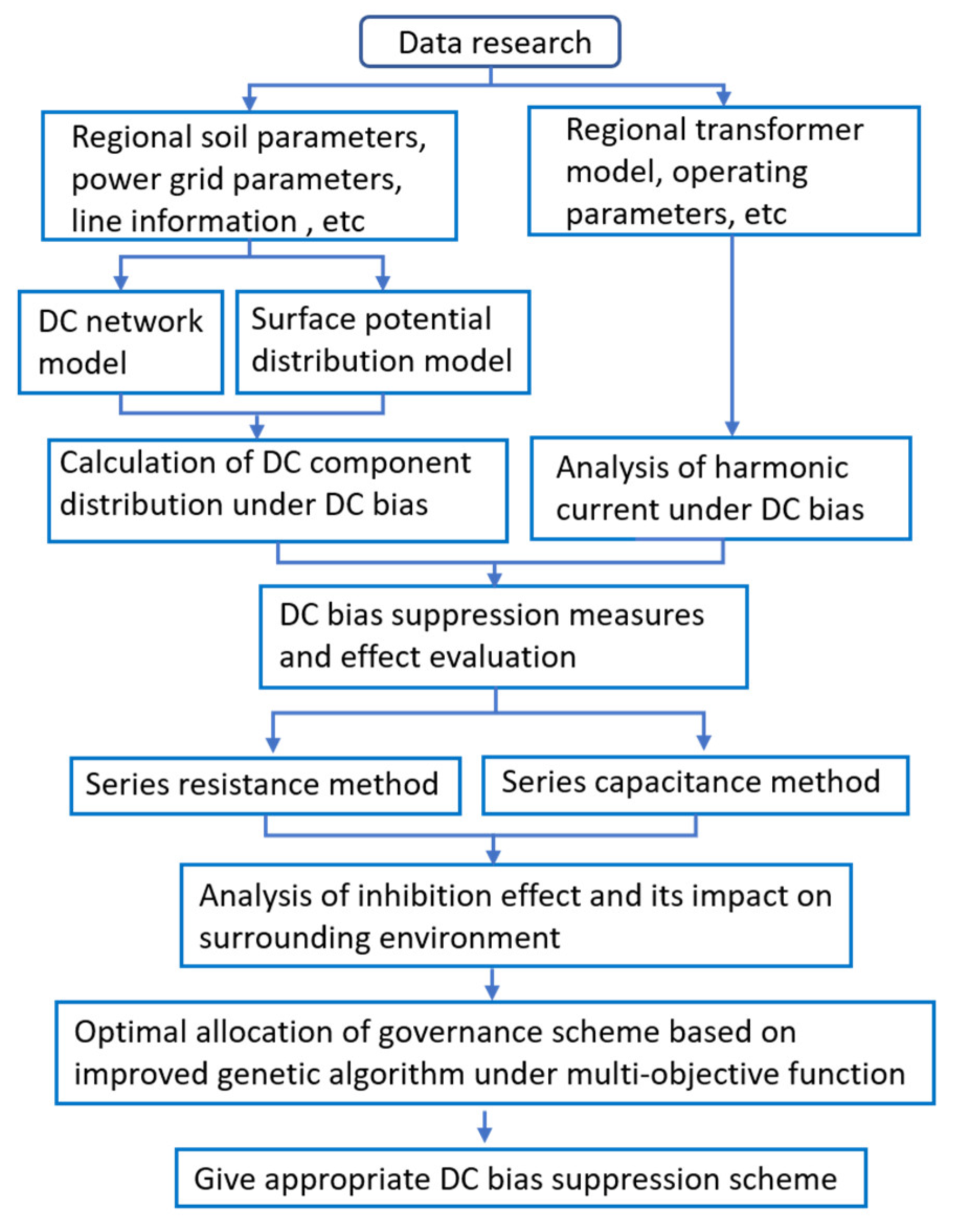
From the perspective of access mode, bypass protection is required for the three suppression methods of connecting equipment in series between the neutral point of the main transformer and the grounding grid. In terms of safety and reliability, the requirements of these three methods for bypass protection are basically at the same level. Therefore, when the bypass protection device reaches the same technical conditions and the same safety and reliability among the three methods of suppressing DC magnetic bias by connecting equipment in series between the neutral point of the main transformer and the ground grid, the method of adding a capacitor DC isolation device to the neutral point of the main transformer is best in terms of effect. The method of adding a small resistance current limiting device to the neutral point of the main transformer is convenient and economical in terms of investment cost. For the specific application of the actual project, it is necessary to conduct a specific analysis, in combination with economic and effectiveness factors, so as to select the appropriate scheme. Figure 6 shows the flow of DC bias calculation and treatment scheme. The whole flow of DC bias research is given from three aspects: DC bias calculation, evaluation of transformer operation characteristics under DC bias conditions, DC bias suppression measures and optimization of configuration scheme. This provides a reference for DC bias research.
5. Conclusions
In this paper, DC bias, a phenomenon of asymmetric operation of power equipment, is summarized as follows:
- The DC bias phenomenon of transformers brings certain harm to the transformer itself and the nearby power grid. According to the source analysis, the DC bias phenomenon is temporarily unavoidable.
- The research methods of transformer DC bias mainly focus on finite element analysis and experimental research. Great progress has been made in the influence of DC bias on transformer electromagnetism, loss and vibration.
- Different methods can be used to suppress the DC bias of transformers, and the operation mode of power systems can also be changed to reduce the impact of DC bias on transformers. At present, the method of series capacitance and resistance is still the mainstream method to suppress the DC bias effect, which can be selected according to the voltage level and operating environment of the transformer.
However, there are still the following problems to be solved:
- It is necessary to further study the quantitative selection of large-scale soil models, and give the typical soil resistivity distribution structure of each region, in combination with the local typical geological structure. It is necessary to further study the shunt effect of lightning rod tower system and establish a more accurate DC current distribution model of AC power grid.
- When magnetic storms and DC transmission projects work together, there is a lack of relevant research to evaluate the DC bias risk of the current power grid. The problems of transformer temperature rise, noise and vibration, caused by DC bias still need to be further studied, especially the combined effect of multiple factors.
- With the formulation of DC bias control standards, the DC withstand capacity of transformers, with different types and working years, differs. The withstand current capacity is related to the material, capacity and type of transformer core, and the withstand capacity cannot be determined only from harmonics, noise or temperature rise.
- At present, the research on the influence of DC magnetic bias on the overall operation of the transformer is relatively comprehensive, but research on the specific influence and mechanism of DC magnetic bias on the internal components of the transformer is not deep enough to support further in-depth research on DC magnetic bias suppression technology.
Author Contributions
Conceptualization, L.Z. and Z.Z.; methodology, D.W.; software, D.W.; validation, Y.S.; formal analysis, Y.S.; investigation, Y.S.; resources, L.Z.; data curation, L.Z.; writing—original draft preparation, Y.S.; writing—review and editing, L.Z.; visualization, Y.S.; supervision, L.Z.; project administration, L.Z.; funding acquisition, Y.S. All authors have read and agreed to the published version of the manuscript.
Funding
This work was supported by the Science and Technology Project of the State Grid Corporation. Research on key technology of suppressing vibration and reducing noise of converter transformers (5500-202124103A-0-0-00).
Data Availability Statement
The study did not report any data.
Conflicts of Interest
The authors declare no conflict of interest.
References
- Vilianen, A.; Pirjola, R. Finnish Geomagnetically Induced Currents Project. IEEE Power Eng. Rev. 2002, 15, 20. [Google Scholar] [CrossRef]
- Pirjola, R. Review on The Calculation of Surface Electric and Magnetic Fields and of Geomagnetically Induced Currents in Ground-Based Technological Systems. Surv. Geophys. 2002, 23, 71–90. [Google Scholar] [CrossRef]
- Towle, J.N.; Prabhakara, F.S.; Ponder, J.Z. Geomagnetic Effects Modelling for the PJM Interconnection System Part I-Earth Surface Potentials Computation. IEEE Trans. Power Syst. 1992, 7, 949–953. [Google Scholar] [CrossRef]
- Boteler, D.H. Effects of Geomagnetically Induced Curents in the B.C. Hydro 500KV System. IEEE Trans. Power Deliv. 1989, 4, 818–823. [Google Scholar] [CrossRef]
- Prabhakara, F.S.; Hannett, L.N.; Ringlee, R.I.; Ponder, J.Z. Geomagnetic effects modelling for the PJM interconnection system. II. Geomagnetically induced current study results. IEEE Trans. Power Syst. 1992, 7, 565–571. [Google Scholar] [CrossRef]
- Dobrovolsky, M.; Kudin, D.; Krasnoperov, R. Unified Geomagnetic Database from Different Observation Networks for Geomagnetic Hazard Assessment Tasks. Data Sci. J. 2020, 19, 34. Available online: https://datascience.codata.org/articles/10.5334/dsj-2020-034/ (accessed on 17 August 2022). [CrossRef]
- Fuchs, E.F.; You, Y. Modeling and simulation, and their validation of three-phase transformers with three legs under DC bias. IEEE Trans. Power Deliv. 1999, 14, 443–449. [Google Scholar] [CrossRef]
- Bozoki, B.; Chano, S.R.; Dvorak, L.L.; Feero, W.E.; Rockefeller, G.D. The effects of GIC on protective relaying. IEEE Trans. Power Deliv. 1996, 11, 725–739. [Google Scholar] [CrossRef]
- Pirjola, R. Geomagnetically induced currents in the Finnish 400 kV power transmission system. Phys. Earth Planet. Inter. 1989, 53, 214–220. [Google Scholar] [CrossRef]
- Boteler, D.H.; Bui-Van, Q. Directional sensitivity to geomagnetically induced currents of the Hydro-Quebec 735 kV power system. IEEE Trans. Power Deliv. 1994, 9, 1963–1971. [Google Scholar] [CrossRef]
- Picher, P.; Bolduc, L. Study of the acceptable DC current limit in core-form power transformers. IEEE Trans. Power Deliv. 1997, 12, 257–265. [Google Scholar] [CrossRef]
- Price, P.R. Geomagnetically Induced Current Effects on Transformers. IEEE Power Eng. Rev. 2002, 22, 62. [Google Scholar] [CrossRef]
- Yu, Y.J.; Yang, Q.; Hou, Z.Y.; Xi, S.; Qi, X.; Wang, L. Influence of earth current of Tianzhong DC project on AC power grid in Hami, Xinjiang. Power Grid Technol. 2014, 38, 2298–2303. [Google Scholar]
- Zou, G.Y.; Yao, H.; He, W.L.; Sun, X.; Wu, Z.D.; Wang, W.G. DC bias control of receiving end grid of Xiluodu West Zhejiang ±800 kV UHV DC transmission project. High Volt. Technol. 2016, 42, 543–550. [Google Scholar]
- Li, C.L.; Tang, X.Y.; Huang, Y.; Luo, K.M.; Xiao, Y.H. Experiment and analysis of the transfer characteristics of TA for metrology under the condition of DC bias. Power Syst. Autom. Equip. 2011, 31, 143–149. [Google Scholar]
- Tan, B.Y.; Lu, J.P.; Jiang, B.; Ai, B. Analysis of the influence of DC bias on the performance of current transformers for metering. Power Grid Technol. 2014, 38, 1408–1413. [Google Scholar]
- Lu, H.L.; Wen, X.S.; Lan, L.; Li, X.P.; Yang, F.Y.; Xu, B.Y.; Li, J.B. Influence of transformer DC bias on reactive power compensation capacitors. High Volt. Technol. 2010, 36, 1124–1130. [Google Scholar]
- Zheng, T.; Chen, P.L.; Liu, L.G.; Liu, C.M.; Mao, A.L. Influence of current transformer transfer characteristics considering DC bias on differential protection. Autom. Electr. Power Syst. 2012, 36, 89–93. [Google Scholar]
- Albertson, V.D.; Bozoki, B.; Feero, W.E.; Kappenman, J.G.; Walling, R. Geomagnetic disturbance effects on power systems. IEEE Trans. Power Deliv. 1993, 8, 1206–1216. [Google Scholar]
- Albertson, V.D.; Thorson, J.M.; Clayton, R.E.; Tripathy, S.C. Solar-Induced-Currents in Power Systems: Cause and Effects. IEEE Trans. Power Appar. Syst. 1973, PAS-92, 471–477. [Google Scholar] [CrossRef]
- Liu, L.G.; Liu, C.M.; Zhang, B.; Wang, Z.Z.; Xiao, X.N.; Han, L.Z. Several strong magnetic storms affecting events of Guangdong power grid in China. Acta Geophys. 2008, 51, 976–981. [Google Scholar]
- Cao, L.; Zhao, J.; Zhang, B.; Zeng, R.; Chen, S.M.; He, J.L. Analysis of linear grounding electrode system for HVDC transmission. High Volt. Technol. 2006, 32, 92–94. [Google Scholar]
- Sun, J.Z.; Liu, L. Using the equivalent complex mirror method to solve the Green’s function of the composite layered soil structure. Chin. J. Electr. Eng. 2003, 23, 146–151. [Google Scholar]
- Guo, J.; Zou, J.; He, J.L.; Han, S.J.; Guan, Z.C. Recursive algorithm of Green’s function of point current source in horizontally layered soil. Chin. J. Electr. Eng. 2004, 24, 101–105. [Google Scholar]
- Pan, Z.H.; Zhang, L.; Tan, B.; Lu, H.L.; Xi, W.S. Theoretical derivation and numerical analysis of the horizontal layered soil grounding problem. High Volt. Technol. 2011, 37, 860–866. [Google Scholar]
- Lu, J.M.; Xiao, D.; Mao, C.X.; Ding, L.J. Influence of DC transmission ground electrode on the distribution of surface potential. High Volt. Technol. 2006, 32, 55–58. [Google Scholar]
- He, J.J.; Ye, H.S.; Lin, F.C.; Li, H.; Gui, Z. The influence of soil structure on the DC current flowing into the neutral point of the transformer. Chin. J. Electr. Eng. 2007, 27, 14–17. [Google Scholar]
- Liu, Q.; Li, L.N.; Zheng, J.C. Current distribution of the HVDC system under the composite soil model when the single pole is operating. Chin. J. Electr. Eng. 2007, 27, 8–13. [Google Scholar]
- Liu, Q.; Zheng, J.C.; Pan, W.; Li, L.N. Simulation and analysis of the ability of transformer core to withstand DC. Transformer 2006, 43, 5–10. [Google Scholar]
- Liu, Q. Research on the Current Distribution in the Ground When the HVDC Transmission System Operates on a Single Pole. Ph.D. Thesis, Tsinghua University, Beijing, China, 2007. [Google Scholar]
- Liu, Q.; Zheng, J.C.L.; Li, L. Research on the DC current at the neutral point of the transformer in the unipolar earth operation of the DC transmission considering the influence of the ocean. Power Grid Technol. 2007, 31, 57–65. [Google Scholar]
- Liu, Q.; Zheng, J.C.L.; Li, L.Z. Influencing factors of current distribution at neutral point of transformer in DC transmission system. High Volt. Technol. 2008, 34, 643–646. [Google Scholar]
- Li, C.Y.; Li, Q.M.; Li, Z.; Yao, J.X.; Liu, M. An extended mirror method for calculating HVDC distribution in the ground under the geological conditions of the peninsula. High Volt. Technol. 2011, 37, 444–452. [Google Scholar]
- Ren, Z.C.; Wu, G.N.; Zhen, W.; Wu, C.; Zhang, Y.K. Simplification and algorithm analysis of the calculation model of the shunting of the DC inflow current through the AC power grid. High Volt. Technol. 2011, 37, 1008–1014. [Google Scholar]
- Zhu, Y.Y.; Jiang, W.P.; Zeng, Z.H.; Yin, Y.H. Research on the measures to suppress the DC current at the neutral point of the transformer. Chin. J. Electr. Eng. 2005, 25, 1–7. [Google Scholar]
- Ma, Z.Q.; Li, X.L.; Zhong, D.Z. A network analysis algorithm for the influence of DC transmission ground current on AC system. Guangdong Electr. Power 2005, 18, 4–8. [Google Scholar]
- Cao, Z.J.; He, J.J.; Ye, H.S.; Lin, F.C. Calculation of DC distribution of AC system when DC system is in ground operation. High Volt. Technol. 2006, 32, 82–84. [Google Scholar]
- Zhang, B.; Zhao, J.; Zeng, R.; He, J.L.; Cui, X. Prediction method of DC current distribution in AC system during DC ground operation. Chin. J. Electr. Eng. 2006, 26, 84–88. [Google Scholar]
- Zeng, R.; Zhao, J.; Shang, C.; Zhang, B. Preventive measures for the influence of HVDC ground direct current on the AC system. High Volt. Technol. 2009, 35, 919–925. [Google Scholar]
- Zeng, R.; Zhang, B.; Zhao, J.; Cai, Z.Y.; Wang, Q.; He, J.L.; Zhang, Z. Influence and law analysis of HVDC ground direct current on AC system. High Volt. Technol. 2009, 35, 678–682. [Google Scholar]
- Cao, L.; Zeng, R.; Zhao, J.; He, J.L.; Zhang, B. Research on the influence of ground electrode current on the operation of power transformer in HVDC transmission system. High Volt. Electr. Appl. 2006, 42, 346–348. [Google Scholar]
- Pan, Z.H.; Zhang, L.; Tan, B.; Mei, G.; Wen, X. Simulation Analysis of HVDC Input Current Distribution in AC Power Grid. Autom. Electr. Power Syst. 2011, 35, 110–115. [Google Scholar]
- Boteler, D.H. Assessment of Geomagnetic Hazard to Power Systems in Canada. Nat. Hazards 2001, 23, 101–120. [Google Scholar] [CrossRef]
- Shi, W.P. Research on the Theory and Algorithm of Ground Induced Potential Along the Transmission Corridor. Ph.D. Thesis, North China Electric Power University, Beijing, China, 2006. [Google Scholar]
- Zheng, K.; Liu, L.G.; Boteler, D.H. GIC-Benchmark Modeling Method for Multi-voltage Level Grid. Chin. Soc. Electr. Eng. 2013, 33, 179–186. [Google Scholar]
- Dawalibi, F.; Barbeito, N. Measurements and computations of the performance of grounding systems buried in multilayer soils. IEEE Trans. Power Deliv. 1991, 6, 1483–1490. [Google Scholar] [CrossRef]
- Villas, J.E.; Portela, C.M. Calculation of Electric Field and Potential Distributions into Soil and Air Media for a Ground Electrode of an HVDC System. IEEE Power Eng. Rev. 2002, 22, 62–63. [Google Scholar] [CrossRef]
- Guo, W. Study on the Performance of Grounding Grid in Complex Soil by Using Boundary Element Method. Ph.D. Thesis, Wuhan University, Wuhan, China, 2013. [Google Scholar]
- Zhou, Y.H.; Li, Q.; Ye, H.F.; Shan, J.C.; Liu, N.; Wang, H.X.; Zhao, X.; Yang, K.Q. Study on the distribution of ESP during the operation of the ground loop of the HVDC system under the n-layer soil model. Electr. Meas. Instrum. 2017, 54, 1–6. [Google Scholar]
- Pan, Z.H.; Zhang, L.; Liu, H.; Lu, H.L.; Wen, X.S. Simulation analysis of surface potential distribution of multi-layer horizontal soil. High Volt. Technol. 2012, 38, 116–123. [Google Scholar]
- Ma, J.J. DC Transmission Grounding Electrode Potential Distribution Considering Geotectonics. Ph.D. Thesis, North China Electric Power University, Beijing, China, 2012. [Google Scholar]
- Chen, D.Z.; Huang, Z.Z.; Liu, J.; Mao, C.X.; Zhang, B.H. Calculation of current field of neutral point current source in horizontally layered soil. High Volt. Technol. 2008, 34, 1379–1382. [Google Scholar]
- Ma, Z.Q. Potential compensation method for reducing transformer neutral DC current and suppressing DC bias. Guangdong Electr. Power 2007, 20, 1–5. [Google Scholar]
- Zhao, J.; Li, X.L.; Lu, J.Z.; Zeng, R.; Niu, B. Series resistance measures to suppress DC bias of transformers. Power Syst. Autom. 2006, 30, 88–91. [Google Scholar]
- Zeng, L.S. Influence of DC transmission grounding electrode current on power transformer. High Volt. Technol. 2005, 31, 57–58. [Google Scholar]
- Oszkar, B.; Gerhard, B.; Gerald, L.; Preis, K. Prediction of Magnetizing Current Wave-Forms in a Three-Phase Power Transformer Under DC Bias. IEEE Trans. Magn. 2008, 44, 1554–1557. [Google Scholar]
- Zhao, Z.G.; Cheng, Z.G.; Liu, F.G.; Liu, L.R.; Wang, Y.H. Simulation of DC bias stray loss characteristics of magnetic conducting steel plate based on magnetic flux leakage compensation. J. Electrotech. 2015, 30, 38–44. [Google Scholar]
- Wang, J.Y.; Bai, B.D.; Ma, C. Influence of DC bias on transformer vibration and noise. J. Electrotech. 2015, 30, 56–61. [Google Scholar]
- Gao, P.; Wang, F.H.; Jiang, Y.M. Vibration characteristics of power transformers under DC bias. Power Grid Technol. 2014, 38, 1536–1541. [Google Scholar]
- Luis, M.; Afshin, R.Z.; Arun, N. Simulation of Transformer Hotspot Heating due to Geomagnetically Induced Currents. IEEE Trans. Power Deliv. 2013, 28, 320–327. [Google Scholar]
- Girgis, R.S.; Ko, C.D. Calculation techniques and results of effects of GIC currents as applied to two large power transformers. In Proceedings of the 1991 IEEE Power Engineering Society Transmission and Distribution Conference, Dallas, TX, USA, 22–27 September 1991; IEEE: New York, NY, USA, 1991. [Google Scholar]
- Walling, R.A.; Khan, A.N. Characteristics of transformer exciting-current during geomagnetic disturbances. IEEE Trans. Power Deliv. 1991, 6, 1707–1714. [Google Scholar] [CrossRef]
- Lu, S.; Liu, Y.L. Harmonies generated from a dc biased transformer. IEEE Trans. Power Deliv. 1993, 8, 725–731. [Google Scholar] [CrossRef]
- Etemadi, A.H.; Rezaei-Zare, A. Optimal Placement of GIC Blocking Devices for Geomagnetic Disturbance Mitigation. IEEE Trans. Power Syst. 2014, 29, 2753–2762. [Google Scholar] [CrossRef]
- Bolduc, L.; Granger, M.; Pare, G.; Saintonge, J.; Brophy, L. Development of a DC current-blocking device for transformer neutrals. IEEE Trans. Power Deliv. 2005, 20, 163–168. [Google Scholar] [CrossRef]
- Yin, Y.H.; Zhang, J.P.; Zhang, H.; Song, D.; Min, X. Development of transformer neutrals DC current blocking device in high power system. In Proceedings of the 2006 International Conference on Power System Technology, Chongqing, China, 22–26 October 2006; pp. 1–6. [Google Scholar]
- Li, C.Y.; Li, Q.M.; Li, Z.; Yao, J.; Liu, M. Suppression measures of transformer DC bias based on dual protection topology. Power Autom. Equip. 2012, 32, 71–75. [Google Scholar]
- Wang, Z.H.; Tong, X.; Qi, W.F. Suppression of transformer DC bias by capacitor direct isolation controllable bridge opening and breaking method. J. Electrotech. 2013, 28, 120–126. [Google Scholar]
- Huang, C.C. Research on Optimal Configuration of DC Bias Suppression Capacitor DC Isolator for Transformer. Ph.D. Thesis, North China Electric Power University, Beijing, China, 2016. [Google Scholar]
- Song, Y.Y.; Wang, Y.H.; Liu, T.Y.; Li, J.; Zhan, W.T. Optimal configuration of capacitor isolator based on multi-objective discrete particle swarm optimization algorithm. Power Grid Technol. 2019, 43, 266–274. [Google Scholar]
- Zhu, H.; Overbye, T. Blocking device placement for mitigating the effects of geomagnetically induced currents. IEEE Trans. Power Syst. 2015, 30, 2081–2089. [Google Scholar] [CrossRef]
- Xiao, H. Research on DC Bias of Transformer Caused by UHV DC Transmission. Ph.D. Thesis, Southwest Jiaotong University, Chengdu, China, 2010. [Google Scholar]
- Ni, L.; Zhao, W.B.; Wang, Z.H.; Jun, M.A. Simulation and solution of the impact of single pole operation of DC system on Shanghai 500 kV power grid. East China Power 2010, 38, 485–489. [Google Scholar]
- Jiang, W.; Huang, Z.; Hu, C.; Zhu, K.; Ren, Z.C. Optimized network configuration of small resistances to limit DC bias current of transformers. Proc. CSEEM 2009, 29, 89–94. [Google Scholar]
- Eitzmann, M.A.; Walling, R.A.; Sublich, M.; Khan, A.H.; Huynh, H.; Granger, M.; Dutil, A. Alternatives for blocking direct current in AC system neutrals at the Radisson/LG2 complex. IEEE Trans. Power Deliv. 1992, 7, 1328–1337. [Google Scholar] [CrossRef]
- Kappenman, J.G.; Norr, S.R.; Sweezy, G.A.; Carlson, D.L.; Damsky, B.L. GIC mitigation: A neutral blocking/bypass device to prevent the flow of GIC in power systems. IEEE Trans. Power Deliv. 1991, 6, 1271–1281. [Google Scholar] [CrossRef]
- Dawalibi, F.P.; Li, Y.; Li, C.; Dong, D.L. Mitigation of Transformer Saturation Due to Neutral HVDC Currents. In Proceedings of the Transmission & Distribution Conference & Exhibition: Asia & Pacific, Dalian, China, 18 August 2005. [Google Scholar]
- Ma, Y.L.; Xiao, X.N.; Jiang, X. Optimal configuration of grounding resistance for suppressing DC bias of large power transformers. Power Grid Technol. 2006, 30, 62–65. [Google Scholar]
- Kuai, D.Z.; Wan, D.; Zou, Y. Application of bias-resisting reverse DC injection at neutral point of transformers. East China Electr. Power 2005, 33, 44–46. [Google Scholar]
- Mao, C.X.; Sheng, W.; Lu, J.M.; Mei, G.; Dan, W. Measures of restraining DC current through transformer neutral point: A comprehensive survey. In Proceedings of the Universities Power Engineering Conference, Brighton, UK, 4–6 September 2007; pp. 707–711. [Google Scholar]
- Pan, Z.H.; Mei, G.H.; Zhang, L.; Tan, B.; Wen, X. Current injection method for suppressing DC bias of transformers. Autom. Power Syst. 2009, 33, 88–911. [Google Scholar]
Figure 1.
Cause of DC magnetic bias: (a) Magnetic flux; (b) Magnetization curve; (c) Excitation current.
Figure 1.
Cause of DC magnetic bias: (a) Magnetic flux; (b) Magnetization curve; (c) Excitation current.

Figure 2.
Distribution principle of DC magnetic bias current under unipolar ground mode operation.
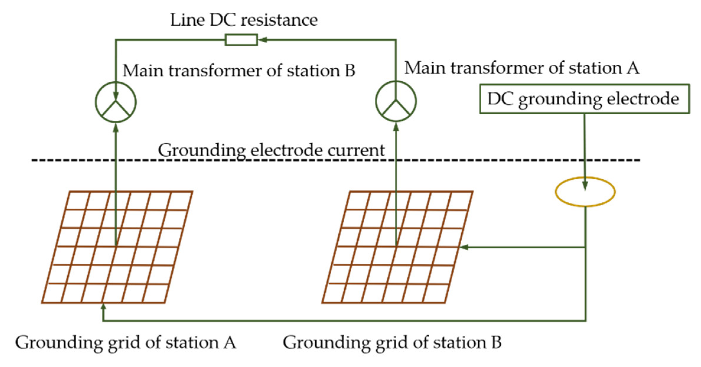
Figure 3.
DC path model of power grid under DC bias.
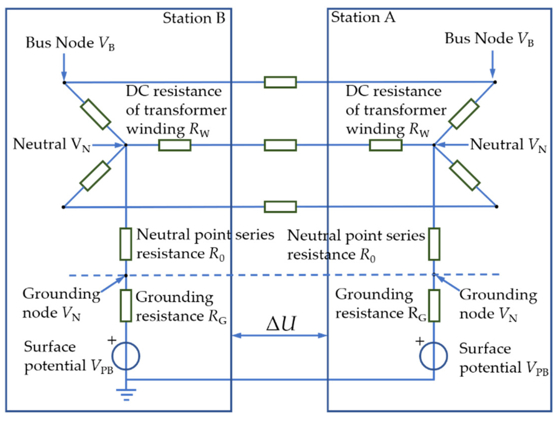
Figure 4.
DC network equivalent model of a 750 kV substation.

Figure 5.
Schematic diagram of current injection method.

Figure 6.
Flow chart of DC bias calculation and suppression scheme.

Table 1.
Comparison of advantages and disadvantages of each inhibition measure.
| Restraining Measures | Advantage | Shortcoming |
|---|---|---|
| Series resistance | 1. The structure and maintenance are simple and reliable. 2. Easy installation and low cost. | 1. DC cannot be completely eliminated. 2. May affect system relay protection. |
| Series capacitance | 1. Fully isolated DC, high security. 2. Little impact on relay protection. 3. Overvoltage can be avoided. | 1. Complex bypass protection. 2. High cost. |
| Current reverse injection | 1. High flexibility. 2. Installation without power failure. 3. Little influence to relay protection. | 1. It needs to be grounded. 2. Low reliability and high cost. |
Publisher’s Note: MDPI stays neutral with regard to jurisdictional claims in published maps and institutional affiliations. |
© 2022 by the authors. Licensee MDPI, Basel, Switzerland. This article is an open access article distributed under the terms and conditions of the Creative Commons Attribution (CC BY) license (https://creativecommons.org/licenses/by/4.0/).
Share and Cite
MDPI and ACS Style
Sun, Y.; Zhang, L.; Zhang, Z.; Wang, D. Overview of Research Status of DC Bias and Its Suppression in Power Transformers. Energies 2022, 15, 8842. https://doi.org/10.3390/en15238842
AMA Style
Sun Y, Zhang L, Zhang Z, Wang D. Overview of Research Status of DC Bias and Its Suppression in Power Transformers. Energies. 2022; 15(23):8842. https://doi.org/10.3390/en15238842
Chicago/Turabian StyleSun, Youliang, Li Zhang, Zhuangzhuang Zhang, and Dong Wang. 2022. "Overview of Research Status of DC Bias and Its Suppression in Power Transformers" Energies 15, no. 23: 8842. https://doi.org/10.3390/en15238842
Note that from the first issue of 2016, this journal uses article numbers instead of page numbers. See further details here.