

Model-Based Investigations of Porous Si-Based Anodes for Lithium-Ion Batteries with Effects of Volume Changes

1
State Key Laboratory of Mechanics and Control of Mechanical Structures, College of Aerospace Engineering, Nanjing University of Aeronautics and Astronautics, Nanjing 210016, China
2
Space Power Technology State Key Laboratory, Shanghai Institute of Space Power-Sources, Shanghai 200245, China
3
Shanghai Institute of Applied Mathematics and Mechanics, School of Mechanics and Engineering Science, Shanghai University, Shanghai 200444, China
*
Author to whom correspondence should be addressed.
Energies 2022, 15(23), 8848; https://doi.org/10.3390/en15238848
Submission received: 3 November 2022
/
Revised: 16 November 2022
/
Accepted: 20 November 2022
/
Published: 23 November 2022
(This article belongs to the Topic Battery Design and Management)
Abstract
:The large volume change of Si has been a roadblock in deploying high-capacity Si-based electrodes in lithium-ion batteries, causing salient structural changes and prominent chemo-mechanical coupled degradation. However, the effects of the volume change of Si-based active materials on the structural parameters have not been fully understood, especially for theoretical prediction through fundamental parameters. In this work, we develop a real-time porosity model featuring volume changes of active materials and electrode dimensions for Si-based anodes, predicting the evolution of porosity and electrode dimensions well through the use of basic electrode parameters. The allowable design space of mass fractions of Si is predicted to be lower than 6% for initial porosity in the range of 26–60% based on the permitted limits of maximum volume change of electrode dimensions and minimum porosity at full lithiation. Subsequently, the effects of changes in porosity and electrode dimensions on the gravimetric and volumetric capacities are emphasized, showing that the accurate estimation of electrochemical performance calls more attention to the effects of structural parameters for Si-based anodes. This study provides a simple and practicable method for the design of electrode parameters, and sheds light on the estimation of electrochemical performance for Si-based anodes.
1. Introduction
In recent years, increasing attention has been paid to lithium-ion batteries (LIBs) thanks to their high capacity, long cycle life, and strict safety, especially for electric vehicles and portable electronics [1,2,3,4]. Despite striking growth in specific energy density, increasing from 150 Wh kg−1 to 300 Wh kg−1 over the last decades [5], the stringent requirements of next-generation batteries originating from the fields of industry technologies are formidable barriers for contemporary commercial LIBs. Si-based LIBs; that is, LIBs with Si-based anodes, have been extensively studied as one of the promising next-generation high-capacity LIBs [6,7,8,9]. As reported, Si-based LIBs with a low mass fraction of the Si active component have been used in practical application, e.g., the batteries in Tesla’s Model 3 [10]. However, several challenges should be addressed prior to large-scale commercial application of Si-based LIBs. The most challenging issue is closely related to the large volume change of active Si particles, on the order of ~300%, during charge and discharge. This causes a series of severe consequences, including but not limited to mechanical damage (e.g., particle fracture, deboning at the particle/binder interface, and separator damage) and reduction of electrochemical performance (e.g., poor cycle life and capacity fade) [11,12,13].
To address the issues around the chemo-mechanical couplings of Si active materials, tremendous efforts have been made to accommodate volume change from the point of view of material and structural engineering strategies. For material engineering strategies, the reported solutions include blended active materials (e.g., Si/graphite composites) [14,15,16], material replacement (e.g., SiOx) [17,18], and novel binders [6,19]. On the other hand, structural engineering strategies are effective at alleviating mechanical degradation and enhancing electrochemical performance, such as nanostructures [20], pore-reserved designs [21], hierarchical structures [22], and other geometric designs [23]. It is worth noting that more than one strategy may be simultaneously used to boost electrode structural durability. Among these strategies, developing composite electrodes incorporating Si along with graphite seems to be the most promising to realize the tradeoff between energy density and cycle life [7]. However, developing Si-based LIBs with stable electrochemical performance and robust mechanical integrity remains challenging.
It is inevitable that Si-based LIBs generate volume changes, as demonstrated by extensive experiments at all scale levels (e.g., particle, electrode, and battery levels) [14,24,25,26]. Generally, volume changes at the electrode and battery levels originate from the volume change at the active particle level, accompanied by the effects of passivation layers, particle movement/rearrangement, elastic–plastic deformation of materials, and space restrictions [27]. Hence, from the point of view of theoretical models, the estimation of volume change of Si-based electrodes and batteries is challenging due to complicated factors, especially for irreversible volume change. Additionally, electrode porosity is one of the critical factors closely linked to certain electro-chemo-mechanical properties and electrochemical performance of batteries (e.g., effective transport properties, mechanical stress, capacity, and side effects) [28,29]. For Si-based electrodes, the change in porosity caused by the volume change of active particles is remarkable [29,30,31]. However, it is not comprehensively understood how these changes evolve in porous electrodes during charge and discharge, and experimental characterization of real-time structural parameters of electrodes without damage remains intractable.
In addition to experimental efforts, theoretical models play a significant role in parameter design and prediction of electrochemical behaviors for Si-based batteries [32,33,34,35,36,37,38]. To date, theoretical methods can be classified into four categories depending on whether volume and porosity changes are considered, as depicted in Figure 1. The first category mimics the behaviors of Si-based electrodes or batteries by ignoring the change in porosity and electrode dimensions (Figure 1a) [33,39]. For example, Jiang et al. established a multi-material porous electrode model without considering the effects of variable porosity and electrode dimensions for Si/graphite electrodes, and quantified the contributions of the individual active materials for different Si/graphite ratios [33]. The second category considers the effects of porosity change for Si-based electrodes with fixed dimensions in theoretical models (Figure 1b) [40,41,42]. Dhillon et al. developed a one-dimension model considering the porosity changes in Si electrodes and solid electrolyte interphase layer growth and investigated the effects of cracking of Si-based electrodes on the capacity fade, ignoring the change in electrode dimensions [40]. The third category takes into account the change in electrode dimensions in theoretical models [43,44], which can predict the swelling of electrodes during cycling, but not the evolution of porosity due to the assumption of constant porosity (Figure 1c). To comprehensively understand the chemo-mechanical behaviors of Si-based LIBs, it is necessary to simultaneously consider the evolution of variable porosity and electrode dimensions caused by the volume change of active particles (i.e., the fourth category, shown in Figure 1d) [34,37,45]. For example, Chen et al. developed a coupled electro-chemo-mechanical model to study the electrochemical and mechanical behaviors of Si-based LIBs, revealing the effects of the design parameters on swelling behavior and electrochemical performance [34].
However, most of these theoretical models for predicting the electrochemical or electro-chemo-mechanical behaviors of Si-based LIBs involve many complex partial differential equations, requiring more computational resources and presenting difficulties in engineering applications. Therefore, it is a meaningful pursuit to obtain the evolution of porosity and electrode dimensions based on the fundamental parameters (e.g., the mass fraction, density, and lithiation expansion coefficient of individual components) for Si-based electrodes, which is conducive to designing electrode parameters and estimating their electrochemical performance simply and directly. For example, Heubner et al. conducted a theoretical optimization of the electrode design parameters of Si-based electrodes with variable porosity and electrode dimensions, using the fundamental information, and determined the design criteria according to the deformation threshold and the C-rate threshold [36]. However, the maximum expansion of electrode dimensions was limited to 10% in Heubner’s work [36], which reduces the design space of the electrode parameters.
Here, a real-time porosity model is established to predict the change in porosity and electrode dimensions for Si-based electrodes. In this model, the effects of volume changes of active particles and electrode dimensions on porosity are included. Subsequently, we focus on the effects of the initial porosity and mass fraction of the Si component on the real-time porosity and electrode dimensions. Based on the maximum volume change limit of electrode dimensions and the minimum porosity limit of electrodes at full lithiation, the allowable design space of initial porosity is provided for different mass fractions of Si. In addition, the effects of variable porosity and electrode dimensions on electrochemical performance (i.e., gravimetric and volumetric capacities) are emphasized, followed by a discussion of the effects of initial porosity and electrode thickness on these capacities.
2. Model Development
2.1. Real-Time Porosity Model
Generally, one electrode is composed of active materials, binder, and conductive additives, and the configuration of these components forms a porous microstructure that is filled with electrolytes during cell assembly. For silicon-based anodes, active materials may contain Si, graphite, or others. The microscale volume change of active particles caused by nano-scale lattice distortion during lithiation and delithiation gives rise to volume change of the electrode and fluctuation of the porosity. The former corresponds to the change in the electrode dimensions that is not fully investigated in battery models, while the latter represents the change in porosity, a critical design parameter closely linked with several transport parameters (e.g., the electrolyte’s conductivity and diffusivity) [42]. In this section, by introducing the relationship between the volume change of active particles and the state of charge (SoC), a SoC-dependent porosity model is developed to investigate the effects of volume changes at the particle and electrode levels. Based on the definition of porosity, the real-time porosity, ε, of a porous electrode during operation can be written as:
where Vi and V are the real-time volumes of the solid phase i and the porous electrode during lithiation, respectively. Similarly, the initial porosity, ε0, of the porous insertion electrode is as follows:
where Vi0 and V0 are the initial volumes of the solid phase i and the porous electrode, respectively. In this work, the solid components in Si-based anode composites consist of Si, graphite (g), a binder (b), and conductive additives (ca). During lithiation and delithiation, the volume of active materials varies with SoC. However, specific SoC-dependent volume expansions are diverse for various active materials because of their different mechanisms of electrochemical lithiation and delithiation [33]. For example, the volume change of graphite, an intercalation material, undergoes a multistage process [24,46], whereas the volume change of Si, an alloyed material, generally has a slope-shaped relationship with SoC [24]. In addition, the charge and discharge behaviors of different active materials in composite electrodes (e.g., Si/graphite electrodes) are the superposition of the contributions of all the active materials, showing non-linear and asymmetric lithiation/delithiation states as a function of SoC inside the electrodes [24,47]. However, in this work, we assume that the individual active materials in the composite anode have approximately the same lithiation state and that the volume expansion of active materials is linearly dependent on SoC, neglecting the effects of irreversible deformation caused by the solid electrolyte interface (SEI), side effects, and particle rearrangement. Therefore, the real-time volume of the individual solid components can be expressed as:
where ηi is the lithiation expansion coefficient of the solid component i and is obtained from experiments or first-principles simulations. Generally, the lithiation expansion coefficients of inactive materials (i.e., binder and conductive additives) are equal to zero. If we know the real-time volume of the composite electrodes, V, the varied porosity, ε, can be obtained according to Equation (1).
How to identify the contributions of the volume change of active particles to the porosity and electrode dimension, respectively, is a question that is both imperative and challenging. Gomadam and Weidner introduced a swelling coefficient, s, to determine the relative magnitudes of changes in electrode dimensions and porosity [37], thereby describing the volume change of electrode dimensions caused by the volume change of active particles as:
where Va and Va0 denote the active particle volumes after and before lithiation, respectively. The swelling coefficient s is dependent on the electrode microstructure (e.g., particle arrangement and electrode porosity) and mechanical properties of electrode components [37,48]. Generally, s is difficult to determine. Furthermore, the porosity is relatively hard to express concisely due to the coupling between s and the porosity. Here, a SoC-dependent swelling coefficient is provided based on the phenomenological approach in order to develop our real-time porosity model [49].
According to Equation (4), the changes in composite electrode dimensions along the electrode thickness direction and two in-plane directions are defined as [37,49]:
where Ln (n = x, y, z) is the electrode dimension in the n-direction during lithiation and Ln0 is the initial electrode dimension before lithiation. Due to the equivalence between Equation (5) and the product of Equations (5)–(7), the corresponding swelling coefficients meet the following relationship:
As mentioned above, sn is difficult to determine.
In general, active particles have diverse shapes and arrangements, leading to the likely expansion of electrodes in any direction. As shown in previous studies [24,35,50,51], the in-plane deformation of electrodes has a negligible effect on the overall volume change of electrodes in comparison with that along the thickness direction, which is owing to the strength and confinement of the current collector as well as the thin and wide geometry. Thus, we assume that the in-plane deformation induced by the volume change of electrode particles is negligible and that the change in thickness of the composite electrodes is only attributed to the expansion of active particles, neglecting the effects of external pressure. As a result, sx = sy = 0 and sz = 1. By substituting sz = 1 into Equation (7), the swelling coefficient s can be written as [49]:
where Δh denotes the relative thickness change of the composite electrode, and ΔVa denotes the relative volume change of the active particles. Rieger et al. proposed a basic correlation between the relative thickness change of electrodes and the relative volume change of the active material particles in order to calculate the swelling coefficient; Based on their simulation results [49], the swelling coefficient is assumed to be predominantly influenced by the active material volume fraction, i.e.,
where ξ denotes the volume fraction of active particles in the composite electrode. It is worth noting that the phenomenological correlation in Equation (10) is obtained based on insufficient experimental parameter variations in numerical simulations and should be verified by extensive experimental investigations and enhanced modeling methods. However, Equation (10) is a relatively convincing way to determine the swelling coefficient s within a certain scope of s [49]. It is worth noting that, in reality, the total thickness change of Si-based electrodes has a certain possibility of exceeding the theoretical limit due to side effects, elastic–plastic deformation, particle rearrangement, and the breakdown of the binder [27,28]. In this work, we make use of Equation (10) to determine the swelling coefficient and believe that this correlation is suitable to roughly approximate the change in composite electrode dimensions. Based on Equations (3) and (10), the corresponding swelling coefficient of the active material i can be expressed as:
where ξi and si denote the volume fraction and the swelling coefficient of the solid component i in the composite electrodes, while si reflects the contribution made by the component i to the electrode dimensions.
Based on Equations (3), (4) and (11), the overall volume change in the composite electrodes arising from the volume change of the active particles is provided by the following governing equation:
Equation (12) is equivalent to the governing equation that is assumed to predict the contribution of the active particle volume change to the overall deformation response for the composite electrodes in the previous battery models [32,52]. The difference is that we can obtain Equation (12) through the defined swelling coefficient s and the relationship in Equation (10), as verified by numerical simulations and experimental results. Here, the swelling coefficient s disappears in the expression. Substituting Equations (2), (3), and (12) into Equation (1), the real-time porosity is expressed as:
For the design of composite electrodes, the mass fractions of solid components are generally known. Based on the mass fraction and the density of individual components, the volume fraction of the respective solid component i in composite electrodes gives:
where j denotes the solid component j and ωi and ρi are the mass fraction and the density, respectively, of the solid component i. Combined with Equations (13) and (14), the real-time porosity model is thereby established. For the specific Si/graphite composite electrode, the real-time porosity is written as:
Here, ηca = ηb = 0 is used in Equation (15) due to there being no intercalation of Li into inactive materials. We can observe from Equations (15) and (16) that when the mass fraction and density of each solid component are determined, the real-time porosity is only dependent on the initial porosity and SoC. Based on the real-time porosity model, we can predict the evolution of the porosity caused by volume changes of the active materials and electrode dimensions during lithiation and then tailor the electrode parameters (e.g., mass fractions and initial porosity) according to the limitations on deformation and the real-time porosity. Furthermore, the real-time volumetric strain, θ, of composite electrodes can be expressed as:
2.2. Electrode Performance
Generally, the gravimetric (Qm) and volumetric (Qv) capacities are estimated based on the initial state of the electrodes, which is suitable for electrodes consisting of conventional battery components with negligible structural changes. However, gravimetric and volumetric capacities may vary with changes in porosity and electrode dimensions, especially for large volume changes in high-capacity electrodes. There have been few studies seeking to identify the effects of structural changes on the real-time gravimetric and volumetric capacities during operation, which are investigated in this work. The gravimetric capacity is defined as:
where mi and Qm,i denote the mass and the theoretical specific capacity of the active component i, respectively, while ρ0 denotes the apparent density of the composite before lithiation, provided by:
Here, a and L0 denote the initial area and the thickness of the composite before lithiation, respectively, while mE denotes the mass of the composite electrode, consisting of the sum of the masses of the composite, electrolyte, and current collector, which is provided by:
where L denotes the thickness of the composite, Lcc denotes the thickness of the current collector, and ρel and ρcc denote the densities of the electrolyte and the current collector, respectively. The real-time apparent density, ρ, of the Si/graphite composite is given by:
where ωLixSi and ωLixC are the mass fractions of LixSi and LiyC in the composite, respectively, which can be determined based on the corresponding mass at the specific SoC:
where MSi, MLi, and MC are the atomic masses of Si, Li, and carbon, respectively. Here, x = 3.75SoC and y = 1/6SoC. The porosity of LixSi, ρLixSi, is approximately:
This is an acceptable error (~10%) compared with that in Kim’s work [53], where ρSi denotes the density of Si. The density of LiyC, ρLiyC, is assumed to be the same as that of graphite [54]. Similarly, the real-time mass percentages of the binder (i.e., ωb-t) and the conductive additive (i.e., ωca-t) are given by:
Based on the assumption that the change in the electrode thickness is dominated during lithiation, the real-time thickness, L, of the composite can be written as:
Combined with Equations (21)–(27), which describe the real-time apparent density and real-time thickness of the composite, the gravimetric capacity of Si/graphite electrodes is expressed as:
Similarly, the volumetric capacity of Si/graphite electrodes is provided by:
Thus, Equations (28) and (29) can be used to investigate the evolution of the gravimetric and volumetric capacities of Si/graphite electrodes with the effects of changes in porosity and electrode dimensions during lithiation.
3. Results and Discussion
3.1. Validation of the Real-Time Porosity Model
Graphite anodes undergo a volume change of 10–12.8% in the lattice, while the volume change of Si anodes can be up to 300% [55,56]. Unless otherwise specified, the parameters employed in this work are those listed in Table 1. Figure 2a shows the evolution of the porosity and volume change of graphite anodes with ξg = 61% and ε0 = 33%. It can be observed that the porosity of graphite electrodes has a slight change of ~2% during lithiation, indicating that the effects of porosity change can be negligible for small-volume-change active materials. The volume change at SoC = 100% predicted by the model is 6.1% for ηg = 0.1 or 6.9% for ηg = 0.11, which is in agreement with experimental observations (~7%) of graphite dilatometry [57]. Here, we choose the following graphite electrode parameters [30,58]: ξg = 90%, ξca = 2%, ξb = 8%, ρca = 1.6 g cm−3, ρb = 1.76 g cm−3, and ε0 = 48%. The predicted change of 2% in porosity is in good agreement with the measured change (2%) obtained by operando X-ray tomographic microscopy, although the volume change of 4.6% is smaller than the experimental value (~7%) [58]. These results suggest that neglecting the change in porosity and electrode dimensions in battery models is reasonable for electrodes composed of small-volume-change active materials, and has no significant effects on accuracy.
Figure 2b shows the evolution of the porosity for Si-based electrodes with ωSi = 50%, ωca = 25%, and ωb= 25% during lithiation. Here, the porosity of the electrode reaches 50 ± 5%, and the densities of polyvinylidene fluoride (PVDF), Nafion, and carbon black are 1.76 g cm−3, 1.97 g cm−3, and 1.60 g cm−3, respectively, which are all collected from the previous report [30]. As shown in Figure 2b, the decreasing trend of the porosity during lithiation can be obtained by the real-time porosity model. In addition, the predicted porosity shows good agreement with the measured values for the Nafion binder [30], verifying the validity of the porosity model. In the case of the PVDF binder, the predicted porosity deviates from the experimental values at the end of lithiation. The difference in accuracy between the two cases may arise from the distinction between the mechanical properties of the two binders; that is, the composite with Nafion is softer than the one with PVDF due to the smaller elastic modulus and hardness of the former [30,31]. The binder with greater mechanical properties exerts stronger constraints on the deformation of active materials and leads to a faster downward trend in porosity. In addition, the elastic modulus of Nafion is closer to the modulus of the binder (i.e., 183 MPa) used in the numerical simulation [49]. Equation (10) may be more suitable for describing the relationship between the change in thickness and the volume change of active materials for the Si-based anode with Nafion compared to the one with PVDF. Therefore, the porosity of Si-based composites with Nafion can be predicted more precisely by the real-time porosity model.
Figure 2c shows the volume change of Si/graphite composite electrodes with different Si/graphite ratios at full lithiation. Here, the mass fractions of Si are 0%, 3%, 5%, 7%, 10%, and 15%, respectively. The mass fractions of conductive additives and the binder are 2% (SuperP with a density of 1.6 g cm−3) and 3% (carboxymethyl cellulose and styrene butadiene rubber with an average density of 1.59 g cm−3), respectively. These parameters of electrodes with an estimated porosity range of 60–72% are collected from the previous report [14]. The initial porosity of 60% is chosen to calculate the volume change (i.e., the thickness change) of electrodes in the model. It is worth noting that the experimental data correspond to the volume changes in the last cycle [14], i.e., the effects of irreversible deformations are assumed to decrease with increasing cycles. It can be seen from Figure 2c that the volume changes predicted by the model are in good agreement with the experimental results [14]. As stated above, the model in this work ignores the irreversible effects (e.g., the formation of SEI, inelastic deformation, and particle movement) that occur in real Si/graphite anodes during lithiation. Thus, while errors between the results of the model and the experiment are inevitable when using the model to predict the volume change for Si-based electrodes after multi-cycle lithiation and delithiation, this is within acceptable bounds.
The aforementioned comparisons between the results obtained with the model and the experimental data show the accuracy and validity of the established real-time porosity model, demonstrating that the change in structural parameters (i.e., porosity and electrode dimension) of Si-based composites can be well predicted by a model that is only dependent on the basic electrode parameters such as the mass fractions, densities, and lithiation expansion coefficients of the solid components and the initial porosity. Therefore, further investigations of the effects of volume change of the active materials on porosity and electrode dimensions can be carried out.
3.2. Model-Based Investigations
For electrodes with large-volume-change active materials, the initial porosity is a critical design index and is closely related to electrochemical performance due to its possible huge change in electrode structures during battery cycling. Figure 3 shows the evolution of the electrode’s porosity and volume change with SoC during lithiation for different initial porosities, obtained from Equations (15) and (17). As expected, the porosity has a descending trend during lithiation, and the volume change of electrodes increases with increasing SoC. The real-time porosity of Si-based electrodes with a single Si active material has a large change amplitude (e.g., 4–30%), which may result in significant fluctuations of electrochemical parameters and performance. In addition, the change in porosity obtained by the model is relatively more moderate in contrast to the case that limits the swelling of the Si-based electrode dimension [36], as in our model the electrode deforms its dimension without extra restrictions. For changes in electrode dimensions and porosity originating from the microscopic deformation of active particles, we can observe from Figure 3 that the former generally accounts for a larger fraction than the latter; that is, the volume change in electrode dimensions is more noticeable than the change in porosity, indicating that allowing electrodes to expand freely alleviates the huge variation in porosity and the relevant mechanical stress inside the electrode. For example, for Si-based electrodes with ωSi = 10%, ωca = 10%, ωb= 10%, ρca = 1.6 g cm−3, ρb = 1.76 g cm−3, and ε0 = 52% [58], the predicted porosity reduction of ~11% and volume expansion of ~29% are comparable with the measured values of 8% and 35%, respectively. However, it is inevitable for Si-based electrodes to suffer constraints imposed by the other battery parts in battery assembly. Furthermore, the large deformation of electrodes requires the corresponding reserved space during the manufacturing process, which damages the accessible energy density of the batteries. In addition, the increasing room provided by the larger initial porosity can better accommodate the volume change of Si particles, causing a decrease in the volume change of electrode dimensions. Therefore, it is necessary to tailor the initial porosity according to the permitted limit of volume change of the electrodes.
The porosity and volume change of a Si-based electrode at SoC = 1 as a function of the initial porosity (SoC = 0) are shown in Figure 4 for different mass fractions of Si. In the case of the pure graphite electrode (i.e., ωSi = 0%), the porosity at SoC = 1 is approximately identical to the initial porosity, because the volume change of graphite is almost accommodated by the change in electrode dimensions according to Equation (15). With increasing ωSi, εSoC=1 deviates from the linear relationship more with ε0. As expected, εSoC=1 decreases with increasing ωSi for the Si-based composite electrodes with the same initial porosity; that is, the initial porosity should be enhanced with increasing ωSi to maintain the same porosity at full lithiation. Again, the change amplitude of porosities is smaller than that of the electrode dimensions for Si-based electrodes. Compared with the swelling limitation of the electrode dimensions [36], the case of total densification (i.e., εSoC=1 = 0) does not occur for the composite with variable ωSi due to the free expansion of electrodes in our model.
In general, volume change of the electrode or battery is undesirable in both the design and practical applications. However, a volume change tolerance of ~5–10% during manufacturing should be allowed to accommodate the deformation generated by the volume expansion of active materials and gases induced by electrolyte decomposition [36,59]. Here, the limited maximum volume change for Si-based electrodes is set to 10%. As shown in Figure 5a, the volume expansion of the composite electrodes increases with rising ωSi. For Si-based electrodes with a typical initial porosity of 60%, the relatively low mass fraction (i.e., in the range of 0–5.7%) of the Si component is a prerequisite to the volume change being lower than the permitted limit. In addition to the limitation of volume change, the accessible porosity should be further discussed according to specific conditions. Due to the impossibility of fully dense electrodes, we define the porosity in a hexagonal close packing of equal spheres as the limited minimum porosity, i.e., ε = 26%. When the real-time porosity is lower than the critical value, the electrode should undergo the mechanical stresses arising from the mutual mechanical interactions of particles. It is worth noting that the particles in real electrodes are likely to suffer mechanical stress when the porosity is larger than the critical value due to the complex arrangement of particles. These built-in mechanical stresses have significant effects on the mechanical integrity and electrochemical performance of electrodes, e.g., particle pulverization, contact loss, and capacity fade. As shown in Figure 5b, the initial porosity should be tailored based on the mass fraction of active materials to alleviate the mechanical stresses. Generally, a larger mass fraction of Si requires a larger initial porosity to accommodate the large volume change of active materials in order for the required εSoC=1 to be no less than 26%. Consequently, the key parameters, e.g., the initial porosity and the mass fraction of active materials, should be regulated according to specific limits of volume change and real-time porosity.
As mentioned above, the initial porosity and the mass fraction of the Si component should be flexibly designed based on the limits of maximum volume change and minimum porosity at SoC = 1. Here, the maximum volume change and the minimum porosity of Si-based anodes are set to 10% and 26%, respectively. The governing inequality constraints are provided by:
Combined with Equations (15) and (17), the allowable region of the initial porosity and the mass fraction of Si can be obtained according to Equations (30) and (31), as depicted in Figure 6. Here, the design space of the initial porosity is in the range of 26–100% in view of the minimum porosity. The aforementioned effects of the volume change of active particles manifest in two forms, i.e., changes in electrode dimensions (θ) and changes in porosity (ε). If one of the two forms is restricted, the other should be liberalized to accommodate the significant volume change in active materials. Thus, we can observe from Figure 6 that the design space of the initial porosity becomes narrow with increasing ωSi for Si-based composite electrodes with variable Si components. Correspondingly, for the typical initial porosity in the range of 26–60% commonly used in engineering practices, the allowable mass fraction of Si is lower than ~6%, providing a reasonable explanation for the fact that commercial Si-based LIBs generally contain a relatively low mass fraction of Si; e.g., Tesla’s Model 3 is said to use a 10% mass fraction of Si in its battery design [10]. Replacing pure Si with SiOx (with a volume change of ~160% during lithiation) is a better compromise between electrochemical performance and mechanical integrity. Similarly, the allowable mass fraction of SiOx can be predicted as being below 11% when initial porosity is in the range of 26–60%. As reported, the weight percentage of graphite and SiOx is estimated to be 90% and 10%, respectively, in LGM50 cells with a SiOx/graphite composite anode [60]. Therefore, the low mass fraction of SiOx in commercial Si-based cells supports our model’s results. Additionally, the allowable design region can be divided into two parts. One part (the left side of the red dash-dotted line in Figure 6) is dominated by Equation (30) due to the relatively low mass fraction of Si in the range of 0–1.6%. When the mass fraction of Si increases to a certain extent (i.e., >1.6%), the inequality constraint in Equation (31); that is, the limit of the maximum volume change in electrode dimensions, plays a dominant role in the initial porosity (right side of the red dash-dotted line in Figure 6). It is worth noting that the allowable design spaces of initial porosity and mass fraction of Si can be flexibly tailored according to the selected limits of maximum volume change in electrode dimensions and minimum porosity at SoC = 1, using the model established by Heubner et al. [36] for comparison.
The aforementioned swelling coefficient is hard to determine. Here, the swelling coefficients of Si and graphite at SoC = 1 are shown in Figure 7 as the initial porosity or the mass fraction of Si varies. The contributions of volume changes in Si and graphite particles to the change in electrode dimensions decrease with increasing ε0 due to more accommodation space inside the electrode. For an electrode with high initial porosity, the greater room generated by the porosity accommodates the volume change of active materials, leading to a small s. Similarly, for a dense electrode with low initial porosity, less room is available to accommodate the volume change of the particles, and the change in electrode dimensions is dominant (i.e., a large s). These features of the swelling coefficient are consistent with the discussions conducted by Gomadam and Weidner [37]. Additionally, the swelling coefficient of Si increases with increasing ωSi, and the swelling coefficient of graphite decreases with increasing ωSi. Regardless, the swelling coefficient relies on a variety of conditions in the Si-based electrodes. In this work, the effects of the porosity and Si/graphite ratios on the swelling coefficient have been considered, ignoring the effects of the arrangement of particles, mechanical properties of the components, and constraints from other parts of the battery.
3.3. Estimation of Electrode Performance
The variable porosity and electrode dimensions during lithiation and delithiation can have significant impacts on the estimation of electrode performance (i.e., gravimetric and volumetric capacities) that can be investigated based on Equations (28) and (29). Figure 8 shows the evolution of the gravimetric and volumetric capacities of Si-based composites during lithiation. The gravimetric and volumetric capacities are kept almost unchanged for low mass fractions of Si due to there being almost no changes in electrode structures, suggesting that the capacity calculated at SoC = 0 can be used to characterize the real-time capacity. In other words, the effects of variable porosity and electrode dimensions on capacity are negligible for electrodes with low mass fractions of the Si component, e.g., ωSi ≤ 10%. However, the gravimetric and volumetric capacities distinctly decrease with increasing SoC during lithiation for electrodes with high mass fractions of Si (e.g., 95%), indicating that the estimation of capacities for Si-based electrodes, especially those with high ωSi, should take into account the effects of changes in electrode structures, i.e., the real-time porosity and electrode dimensions in this work. It is worth noting that the effects of changes in porosity and electrode dimensions on specific capacity are rarely investigated or emphasized in the reported studies. For example, the capacities are often estimated based on the initial electrode parameters of Si-based electrodes, making them independent of SoC [33,36]. The model in this work, on the other hand, highlights the prominent role of volume change in the estimation of electrode electrochemical performance.
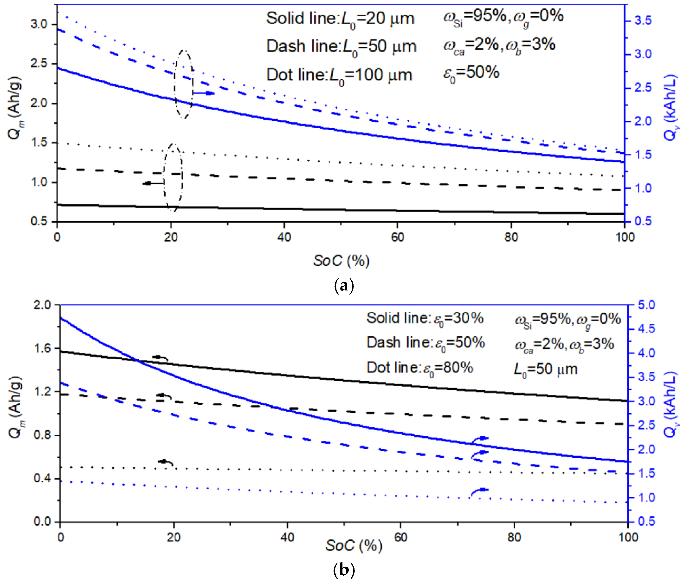
To further estimate the effects of different electrode parameters on the capacities, electrodes with different thicknesses or initial porosities are investigated, as shown in Figure 9. Apparently, both capacities reduce with increasing SoC for different cases, showing the important impacts of changes in electrode structures. Additionally, the change amplitude of the volumetric capacity is larger than that of the gravimetric capacity for different thicknesses and initial porosities, as the former is dominated by the prominent volume change of the electrode. As expected, the gravimetric and volumetric capacities decrease with decreasing electrode thickness and increasing initial porosity, showing that developing electrodes with high thickness and low porosity is an efficient solution for high-capacity LIBs. In light of the challenges of poor rate performance and electrode mechanical instability [61,62,63], it is necessary to tailor the electrode thickness and the initial porosity for high-energy Si-based electrodes while considering the effects of electrode structure on the estimation of the gravimetric and volumetric capacities.
4. Conclusions
Based on the fact that the volume change of active particles at the microscale induces changes in porosity and electrode dimensions, in this paper a real-time porosity model for Si-based electrodes is established, featuring the deformation of active particles and electrode dimensions. The results show that changes in porosity and electrode dimensions predicted by the model are plausible, with an acceptable error compared with the reported experimental results. The effects of variable porosity and electrode dimensions are negligible for electrodes with small-volume-change active materials. For large-volume-change Si-based electrodes, however, the change amplitudes of the porosity and electrode dimensions may be variable over a broad range, and should be considered in theoretical and numerical simulations. We provide the accessible design space of the initial porosity and mass fractions of Si based on the limits of the maximum volume change of electrodes and the minimum porosity at SoC = 1, requiring that the initial porosity in the range of 26–60%, as commonly used in Si-based electrodes, corresponds to a very low mass fraction of Si (< 6%).
The effects of variable porosity and electrode dimensions on electrochemical performance, i.e., gravimetric and volumetric capacities, are further investigated for Si-based electrodes with different electrode parameters, e.g., the mass fraction of Si, the thickness, and the initial porosity. These capacities can be calculated based on the initial state of electrodes with a low mass fraction of Si. However, it is necessary to consider the impacts of changes in porosity and electrode dimensions for estimation of the capacities of Si-based electrodes with a relatively high mass fraction of Si due to their significant reduction during lithiation. Thick electrodes with low porosity show huge potential for improvements in capacity. These results can shed light on electrode parameter design and estimation of electrochemical performance for large-volume-change Si-based electrodes in high-capacity LIBs.
Theoretical models only dependent on fundamental electrode parameters are conducive to engineering applications. However, the model established in this work neglects irreversible factors, e.g., the effects of SEI, which could be introduced into the current model to enhance accuracy. Additionally, the focus of this study is only on Si-based electrodes. The design of electrode parameters for full cells with Si-based anodes should be investigated in the future. Due to the lack of chemo-mechanical couplings in this work, incorporating the real-time model into reported chemo-mechanical coupled models would be meaningful and helpful in more fully understanding chemo-mechanical coupled behaviors along with the effects of changes in porosity and electrode dimensions in Si-based LIBs.
Author Contributions
Conceptualization and methodology, X.Z.; validation and formal analysis, X.Z. and J.C.; writing—original draft preparation, X.Z.; writing—review and editing, Y.B.; supervision, X.Z. and Y.B.; project administration and funding acquisition, X.Z. All authors have read and agreed to the published version of the manuscript.
Funding
This research was funded by the National Natural Science Foundation of China (Grant No. 11902149), Natural Science Foundation of Jiangsu Province (Grant No. BK20190380), China Postdoctoral Science Foundation (Grant No.2021TQ0153) and China Scholarship Council (Grant No. 202006835040).
Conflicts of Interest
The authors declare no conflict of interest. The funders had no role in the design of the study, in the collection, analyses, or interpretation of data, in the writing of the manuscript, or in the decision to publish the results.
References
- Xia, H.; Tang, Y.; Malyi, O.I.; Zhu, Z.; Zhang, Y.; Zhang, W.; Ge, X.; Zeng, Y.; Chen, X. Deep cycling for high-capacity Li-ion batteries. Adv. Mater. 2021, 33, 2004998. [Google Scholar] [CrossRef]
- Mabokela, T.E.; Nwanya, A.C.; Ndipingwi, M.M.; Kaba, S.; Ekwere, P.; Werry, S.T.; Ikpo, C.O.; Modibane, K.D.; Iwuoha, E.I. Review—Recent advances on high-capacity Li ion-rich layered manganese oxide cathodes. J. Electrochem. Soc. 2021, 168, 70530. [Google Scholar] [CrossRef]
- Jiang, M.; Danilov, D.L.; Eichel, R.A.; Notten, P.H.L. A review of degradation mechanisms and recent achievements for Ni-rich cathode-based Li-ion batteries. Adv. Energy Mater. 2021, 11, 2103005. [Google Scholar] [CrossRef]
- Lin, Q.; Guan, W.; Meng, J.; Huang, W.; Wei, X.; Zeng, Y.; Li, J.; Zhang, Z. A new insight into continuous performance decay mechanism of Ni-rich layered oxide cathode for high energy lithium ion batteries. Nano Energy 2018, 54, 313–321. [Google Scholar] [CrossRef]
- Liu, Y.; Zhang, R.; Wang, J.; Wang, Y. Current and future lithium-ion battery manufacturing. iScience 2021, 24, 102332. [Google Scholar] [CrossRef]
- Zhao, Y.M.; Yue, F.S.; Li, S.C.; Zhang, Y.; Tian, Z.R.; Xu, Q.; Xin, S.; Guo, Y.G. Advances of polymer binders for silicon-based anodes in high energy density lithium-ion batteries. InfoMat 2021, 3, 460–501. [Google Scholar] [CrossRef]
- Li, P.; Kim, H.; Myung, S.; Sun, Y. Diverting exploration of silicon anode into practical way: A review focused on silicon-graphite composite for lithium ion batteries. Energy Storage Mater. 2021, 35, 550–576. [Google Scholar] [CrossRef]
- Zhang, C.Z.; Wang, F.; Han, J.; Bai, S.; Tan, J.; Liu, J.S.; Li, F. Challenges and recent progress on silicon-based anode materials for next-generation lithium-ion batteries. Small Struct. 2021, 2, 2100009. [Google Scholar] [CrossRef]
- De Sutter, L.; Berckmans, G.; Marinaro, M.; Smekens, J.; Firouz, Y.; Wohlfahrt-Mehrens, M.; van Mierlo, J.; Omar, N. Comprehensive aging analysis of volumetric constrained lithium-ion pouch cells with high concentration silicon-alloy anodes. Energies 2018, 11, 2948. [Google Scholar] [CrossRef] [Green Version]
- Deng, Y.; Ma, L.; Li, T.; Li, J.; Yuan, C. Life cycle assessment of silicon-nanotube-based lithium ion battery for electric vehicles. ACS Sustain. Chem. Eng. 2019, 7, 599–610. [Google Scholar] [CrossRef]
- Zhang, X.; Bao, Y.; Chen, J.; Chen, H. Heterogeneous effects on chemo-mechanical coupling behaviors at the single-particle level. J. Electrochem. Soc. 2022, 169, 010522. [Google Scholar] [CrossRef]
- Tan, D.; Chen, Y.T.; Yang, H.; Bao, W.; Sreenarayanan, B.; Doux, J.M.; Li, W.; Lu, B.; Ham, S.Y.; Sayahpour, B.; et al. Carbon-free high-loading silicon anodes enabled by sulfide solid electrolytes. Science 2021, 373, 1494–1499. [Google Scholar] [CrossRef]
- Liang, H.; Zhang, X.; Yang, L.; Wu, Y.; Chen, H.; Song, W.; Fang, D. Electrochemomechanical coupled behaviors of deformation and failure in electrode materials for lithium-ion batteries. Sci. China Technol. Sci. 2019, 62, 1277–1296. [Google Scholar] [CrossRef]
- Moyassari, E.; Roth, T.; Kucher, S.; Chang, C.C.; Hou, S.C.; Spingler, F.B.; Jossen, A. The role of silicon in silicon-graphite composite electrodes regarding specific capacity, cycle stability, and expansion. J. Electrochem. Soc. 2022, 169, 010504. [Google Scholar] [CrossRef]
- Li, P.; Hwang, J.Y.; Sun, Y.K. Nano/microstructured silicon-graphite composite anode for high-energy-density Li-ion battery. ACS Nano 2019, 13, 2624–2633. [Google Scholar] [CrossRef]
- Si, Q.; Mori, D.; Takeda, Y.; Yamamoto, O.; Imanishi, N. Silicon-carbon composite electrode materials prepared by pyrolysis of a mixture of manila hemp, silicon powder, and flake artificial graphite for lithium batteries. Energies 2017, 10, 1803. [Google Scholar] [CrossRef] [Green Version]
- Fu, R.; Ji, J.; Yun, L.; Jiang, Y.; Zhang, J.; Zhou, X.; Liu, Z. Graphene wrapped silicon suboxides anodes with suppressed Li-uptake behavior enabled superior cycling stability. Energy Storage Mater. 2021, 35, 317–326. [Google Scholar] [CrossRef]
- Li, G.; Li, J.; Yue, F.; Xu, Q.; Zuo, T.; Yin, Y.; Guo, Y. Reducing the volume deformation of high capacity SiOx/G/C anode toward industrial application in high energy density lithium-ion batteries. Nano Energy 2019, 60, 485–492. [Google Scholar] [CrossRef]
- Yu, Y.Y.; Zhu, J.D.; Zeng, K.; Jiang, M.J. Mechanically robust and superior conductive n-type polymer binders for high-performance micro-silicon anodes in lithium-ion batteries. J. Mater. Chem. A 2021, 9, 3472–3481. [Google Scholar] [CrossRef]
- Jeong, Y.K.; Huang, W.; Vilá, R.A.; Huang, W.; Wang, J.; Kim, S.C.; Kim, Y.S.; Zhao, J.; Cui, Y. Microclusters of Kinked Silicon Nanowires Synthesized by a Recyclable Iodide Process for High-Performance Lithium-Ion Battery Anodes. Adv. Energy Mater. 2020, 10, 2002108. [Google Scholar] [CrossRef]
- An, W.; Gao, B.; Mei, S.; Xiang, B.; Fu, J.; Wang, L.; Zhang, Q.; Chu, P.K.; Huo, K. Scalable synthesis of ant-nest-like bulk porous silicon for high-performance lithium-ion battery anodes. Nat. Commun. 2019, 10, 1447. [Google Scholar] [CrossRef] [Green Version]
- Jia, H.; Li, X.; Song, J.; Zhang, X.; Luo, L.; He, Y.; Li, B.; Cai, Y.; Hu, S.; Xiao, X.; et al. Hierarchical porous silicon structures with extraordinary mechanical strength as high-performance lithium-ion battery anodes. Nat. Commun. 2020, 11, 1474. [Google Scholar] [CrossRef] [Green Version]
- Baggetto, L.; Danilov, D.; Notten, P.H. Honeycomb-structured silicon: Remarkable morphological changes induced by electrochemical (de)lithiation. Adv. Mater. 2011, 23, 1563–1566. [Google Scholar] [CrossRef]
- Louli, A.J.; Li, J.; Trussler, S.; Fell, C.R.; Dahn, J.R. Volume, pressure and thickness evolution of Li-ion pouch cells with silicon-composite negative electrodes. J. Electrochem. Soc. 2017, 164, A2689–A2696. [Google Scholar] [CrossRef]
- McDowell, M.T.; Lee, S.W.; Harris, J.T.; Korgel, B.A.; Wang, C.M.; Nix, W.D.; Cui, Y. In situ TEM of two-phase lithiation of amorphous silicon nanospheres. Nano Lett. 2013, 13, 758–764. [Google Scholar] [CrossRef]
- Timmons, A.; Dahn, J.R. In situ optical observations of particle motion in alloy negative electrodes for Li-ion batteries. J. Electrochem. Soc. 2006, 153, A1206–A1210. [Google Scholar] [CrossRef]
- Yu, D.; Zhao, M.; Hoster, H.E. Suppressing vertical displacement of lithiated silicon particles in high volumetric capacity battery electrodes. ChemElectroChem 2015, 2, 1090–1095. [Google Scholar] [CrossRef]
- Profatilova, I.; De Vito, E.; Genies, S.; Vincens, C.; Gutel, E.; Fanget, O.; Martin, A.; Chandesris, M.; Tulodziecki, M.; Porcher, W. Impact of silicon/graphite composite electrode porosity on the cycle life of 18650 lithium-ion cell. ACS Appl. Energy Mater. 2020, 3, 11873–11885. [Google Scholar] [CrossRef]
- Bridel, J.S.; Azaïs, T.; Morcrette, M.; Tarascon, J.M.; Larcher, D. Key parameters governing the reversibility of Si/carbon/CMC electrodes for Li-ion batteries. Chem. Mater. 2010, 22, 1229–1241. [Google Scholar] [CrossRef]
- Wang, Y.; Dang, D.; Li, D.; Hu, J.; Cheng, Y. Influence of polymeric binders on mechanical properties and microstructure evolution of silicon composite electrodes during electrochemical cycling. J. Power Source 2019, 425, 170–178. [Google Scholar] [CrossRef]
- Xu, J.; Zhang, L.; Wang, Y.; Chen, T.; Al-Shroofy, M.; Cheng, Y.T. Unveiling the critical role of polymeric binders for silicon negative electrodes in lithium-ion full cells. ACS Appl. Mater. Interfaces 2017, 9, 3562–3569. [Google Scholar] [CrossRef]
- Ai, W.; Kirkaldy, N.; Jiang, Y.; Offer, G.; Wang, H.; Wu, B. A composite electrode model for lithium-ion batteries with silicon/graphite negative electrodes. J. Power Source 2022, 527, 231142. [Google Scholar] [CrossRef]
- Jiang, Y.; Niu, Z.; Offer, G.; Xuan, J.; Wang, H. Insights into the role of silicon and graphite in the electrochemical performance of silicon/graphite blended electrodes with a multi-material porous electrode model. J. Electrochem. Soc. 2022, 169, 020568. [Google Scholar] [CrossRef]
- Chen, Y.; Yang, L.; Guo, F.; Liu, D.; Wang, H.; Lu, J.; Zheng, J.; Yu, X.; Li, H. Mechanical-electrochemical modeling of silicon-graphite composite anode for lithium-ion batteries. J. Power Source 2022, 527, 231178. [Google Scholar] [CrossRef]
- Zhang, X.; Klinsmann, M.; Chumakov, S.; Li, X.; Kim, S.U.; Metzger, M.; Besli, M.M.; Klein, R.; Linder, C.; Christensen, J. A modified electrochemical model to account for mechanical effects due to lithium intercalation and external pressure. J. Electrochem. Soc. 2021, 168, 20533. [Google Scholar] [CrossRef]
- Heubner, C.; Langklotz, U.; Michaelis, A. Theoretical optimization of electrode design parameters of Si based anodes for lithium-ion batteries. J. Energy Storage 2018, 15, 181–190. [Google Scholar] [CrossRef]
- Gomadam, P.M.; Weidner, J.W. Modeling volume changes in porous electrodes. J. Electrochem. Soc. 2006, 153, A179–A186. [Google Scholar] [CrossRef] [Green Version]
- Dasari, H.; Eisenbraun, E. Predicting Capacity Fade in Silicon Anode-Based Li-Ion Batteries. Energies 2021, 14, 1448. [Google Scholar] [CrossRef]
- Wang, M.; Xiao, X.; Huang, X. A multiphysics microstructure-resolved model for silicon anode lithium-ion batteries. J. Power Source 2017, 348, 66–79. [Google Scholar] [CrossRef]
- Dhillon, S.; Hernández, G.; Wagner, N.P.; Svensson, A.M.; Brandell, D. Modelling capacity fade in silicon-graphite composite electrodes for lithium-ion batteries. Electrochim. Acta 2021, 377, 138067. [Google Scholar] [CrossRef]
- Sturm, J.; Rheinfeld, A.; Zilberman, I.; Spingler, F.B.; Kosch, S.; Frie, F.; Jossen, A. Modeling and simulation of inhomogeneities in a 18650 nickel-rich, silicon-graphite lithium-ion cell during fast charging. J. Power Source 2019, 412, 204–223. [Google Scholar] [CrossRef] [Green Version]
- Chandrasekaran, R.; Fuller, T.F. Analysis of the lithium-ion insertion silicon composite electrode/separator/lithium foil cell. J. Electrochem. Soc. 2011, 158, A859–A871. [Google Scholar] [CrossRef]
- Gao, X.; Lu, W.; Xu, J. Modeling framework for multiphysics-multiscale behavior of Si–C composite anode. J. Power Source 2020, 449, 227501. [Google Scholar] [CrossRef]
- Liu, B.; Jia, Y.; Li, J.; Jiang, H.; Yin, S.; Xu, J. Multiphysics coupled computational model for commercialized Si/graphite composite anode. J. Power Source 2020, 450, 227667. [Google Scholar] [CrossRef]
- Shah, S.R.; de Vasconcelos, L.S.; Zhao, K.J. Computational modeling of electrochemomechanics of high-capacity composite electrodes in Li-ion batteries. J. Appl. Mech. 2022, 89, 081005. [Google Scholar] [CrossRef]
- Michael, H.; Iacoviello, F.; Heenan, T.M.M.; Llewellyn, A.; Weaving, J.S.; Jervis, R.; Brett, D.J.L.; Shearing, P.R. A dilatometric study of graphite electrodes during cycling with X-ray computed tomography. J. Electrochem. Soc. 2021, 168, 10507. [Google Scholar] [CrossRef]
- Yao, K.P.C.; Okasinski, J.S.; Kalaga, K.; Almer, J.D.; Abraham, D.P. Operando quantification of (de)lithiation behavior of silicon–graphite blended electrodes for lithium-ion batteries. Adv. Energy Mater. 2019, 9, 1803380. [Google Scholar] [CrossRef]
- Fu, R.; Xiao, M.; Choe, S. Modeling, validation and analysis of mechanical stress generation and dimension changes of a pouch type high power Li-ion battery. J. Power Source 2013, 224, 211–224. [Google Scholar] [CrossRef]
- Rieger, B.; Schlueter, S.; Erhard, S.V.; Jossen, A. Strain propagation in lithium-ion batteries from the crystal structure to the electrode level. J. Electrochem. Soc. 2016, 163, A1595–A1606. [Google Scholar] [CrossRef]
- Zhang, X.; He, J.; Zhou, J.; Chen, H.; Song, W.; Fang, D. Thickness evolution of commercial Li-ion pouch cells with silicon-based composite anodes and NCA cathodes. Sci. China Technol. Sci. 2021, 64, 83–90. [Google Scholar] [CrossRef]
- Beaulieu, L.Y.; Eberman, K.W.; Turner, R.L.; Krause, L.J.; Dahn, J.R. Colossal reversible volume changes in lithium alloys. Electrochem. Solid-State Lett. 2001, 4, A137–A140. [Google Scholar] [CrossRef]
- Pereira, D.J.; Weidner, J.W.; Garrick, T.R. The effect of volume change on the accessible capacities of porous silicon-graphite composite anodes. J. Electrochem. Soc. 2019, 166, A1251–A1256. [Google Scholar] [CrossRef]
- Kim, H.; Chou, C.; Ekerdt, J.G.; Hwang, G.S. Structure and properties of Li−Si alloys: A first-principles study. J. Phys. Chem. C 2011, 115, 2514–2521. [Google Scholar] [CrossRef]
- Doh, C.; Han, B.; Jin, B.; Gu, H. Structures and formation energies of LixC6 (x = 1–3) and its homologues for lithium rechargeable batteries. Bull. Korean Chem. Soc. 2011, 32, 2045–2050. [Google Scholar] [CrossRef] [Green Version]
- Woodford, W.H.; Carter, W.C.; Chiang, Y. Design criteria for electrochemical shock resistant battery electrodes. Energy Environ. Sci. 2012, 5, 8014–8024. [Google Scholar] [CrossRef]
- Qi, Y.; Guo, H.; Hector, L.G.; Timmons, A. Threefold increase in the young’s modulus of graphite negative electrode during lithium intercalation. J. Electrochem. Soc. 2010, 157, A558–A566. [Google Scholar] [CrossRef]
- Rieger, B.; Schlueter, S.; Erhard, S.V.; Schmalz, J.; Reinhart, G.; Jossen, A. Multi-scale investigation of thickness changes in a commercial pouch type lithium-ion battery. J. Energy Storage 2016, 6, 213–221. [Google Scholar] [CrossRef]
- Pietsch, P.; Westhoff, D.; Feinauer, J.; Eller, J.; Marone, F.; Stampanoni, M.; Schmidt, V.; Wood, V. Quantifying microstructural dynamics and electrochemical activity of graphite and silicon-graphite lithium ion battery anodes. Nat. Commun. 2016, 7, 12909. [Google Scholar] [CrossRef] [Green Version]
- Lee, J.H.; Lee, H.M.; Ahn, S. Battery dimensional changes occurring during charge/discharge cycles—thin rectangular lithium ion and polymer cells. J. Power Source 2003, 119–121, 833–837. [Google Scholar] [CrossRef]
- Chen, C.; Brosa Planella, F.; O’Regan, K.; Gastol, D.; Widanage, W.D.; Kendrick, E. Development of experimental techniques for parameterization of multi-scale lithium-ion battery models. J. Electrochem. Soc. 2020, 167, 80534. [Google Scholar] [CrossRef]
- Zhang, X.; Hui, Z.; King, S.; Wang, L.; Ju, Z.; Wu, J.; Takeuchi, K.J.; Marschilok, A.C.; West, A.C.; Takeuchi, E.S.; et al. Tunable porous electrode architectures for enhanced li-ion storage kinetics in thick electrodes. Nano Lett. 2021, 21, 5896–5904. [Google Scholar] [CrossRef]
- Kuang, Y.; Chen, C.; Kirsch, D.; Hu, L. Thick electrode batteries: Principles, opportunities, and challenges. Adv. Energy Mater. 2019, 9, 1901457. [Google Scholar] [CrossRef]
- Zheng, H.; Li, J.; Song, X.; Liu, G.; Battaglia, V.S. A comprehensive understanding of electrode thickness effects on the electrochemical performances of Li-ion battery cathodes. Electrochim. Acta 2012, 71, 258–265. [Google Scholar] [CrossRef]
Figure 1.
Schematics of electrode structures during lithiation with (a) no change in porosity and volume, (b) variable porosity and invariable volume, (c) variable volume and invariable porosity, and (d) variable porosity and volume.
Figure 1.
Schematics of electrode structures during lithiation with (a) no change in porosity and volume, (b) variable porosity and invariable volume, (c) variable volume and invariable porosity, and (d) variable porosity and volume.

Figure 2.
(a) The evolution of porosity and volume change for graphite anodes during lithiation. (b) The evolution of porosity for Si-based composites during lithiation. (c) The volume change of Si/graphite composites with different ratios at full lithiation. Here, the experimental data are collected from the previous reports [14,30,57].

Figure 3.
The evolution of porosity and volume strain with SoC for different initial porosities.
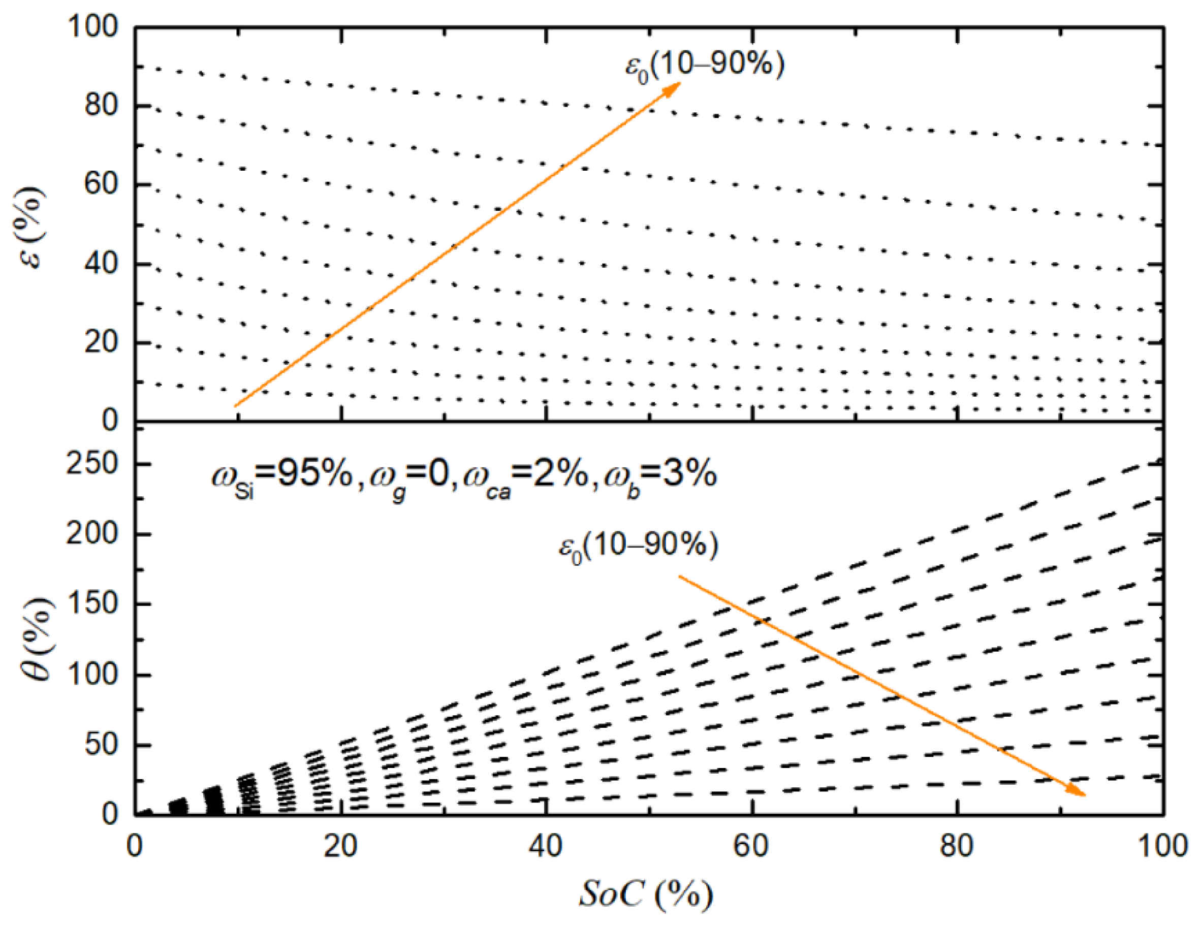
Figure 4.
The porosity and volume change of the electrode at SoC = 1 as a function of the initial porosity (SoC = 0) for different mass fractions of Si.
Figure 4.
The porosity and volume change of the electrode at SoC = 1 as a function of the initial porosity (SoC = 0) for different mass fractions of Si.
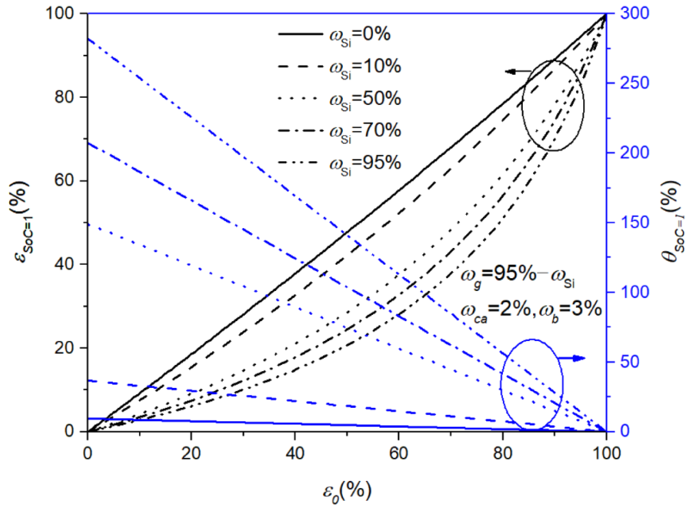
Figure 5.
The evolution of (a) the change in electrode dimensions with ε0 = 60% for different ωSi and (b) the porosity of electrodes with ωSi = 10% for different ε0.
Figure 5.
The evolution of (a) the change in electrode dimensions with ε0 = 60% for different ωSi and (b) the porosity of electrodes with ωSi = 10% for different ε0.

Figure 6.
The design space of the initial porosity and the mass fraction of the Si component based on the limits of maximum volume change and minimum porosity for Si-based composite electrodes at SoC = 1.
Figure 6.
The design space of the initial porosity and the mass fraction of the Si component based on the limits of maximum volume change and minimum porosity for Si-based composite electrodes at SoC = 1.
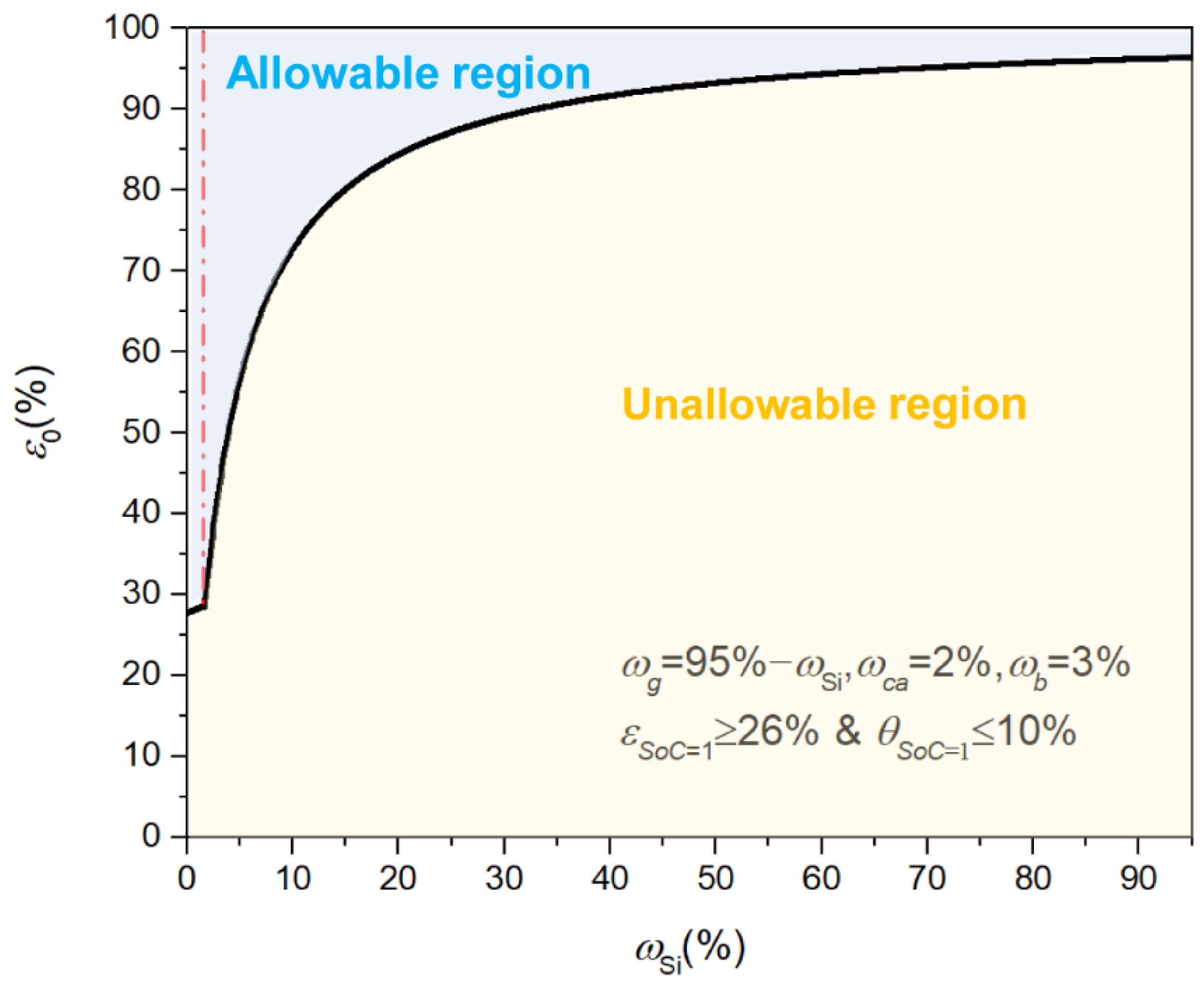
Figure 7.
The swelling coefficients of Si and graphite for the Si-based electrode (a) as a function of ε0 with ωSi = 15% at SoC = 1 and (b) as a function of ωSi for the Si-based electrode with ε0= 60% at SoC = 1.
Figure 7.
The swelling coefficients of Si and graphite for the Si-based electrode (a) as a function of ε0 with ωSi = 15% at SoC = 1 and (b) as a function of ωSi for the Si-based electrode with ε0= 60% at SoC = 1.
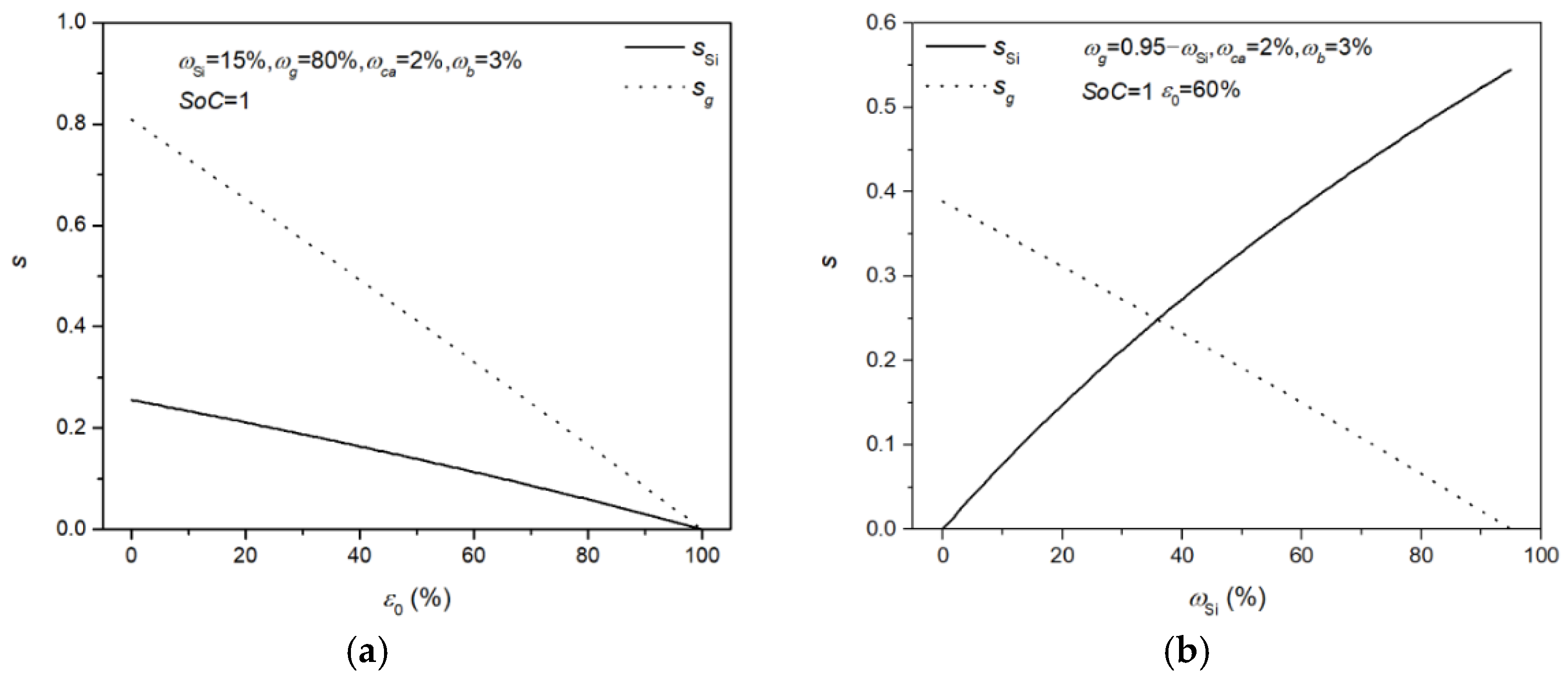
Figure 8.
The evolution of gravimetric and volumetric capacity of Si-based electrodes for different mass fractions of Si as a function of SoC during lithiation.
Figure 8.
The evolution of gravimetric and volumetric capacity of Si-based electrodes for different mass fractions of Si as a function of SoC during lithiation.
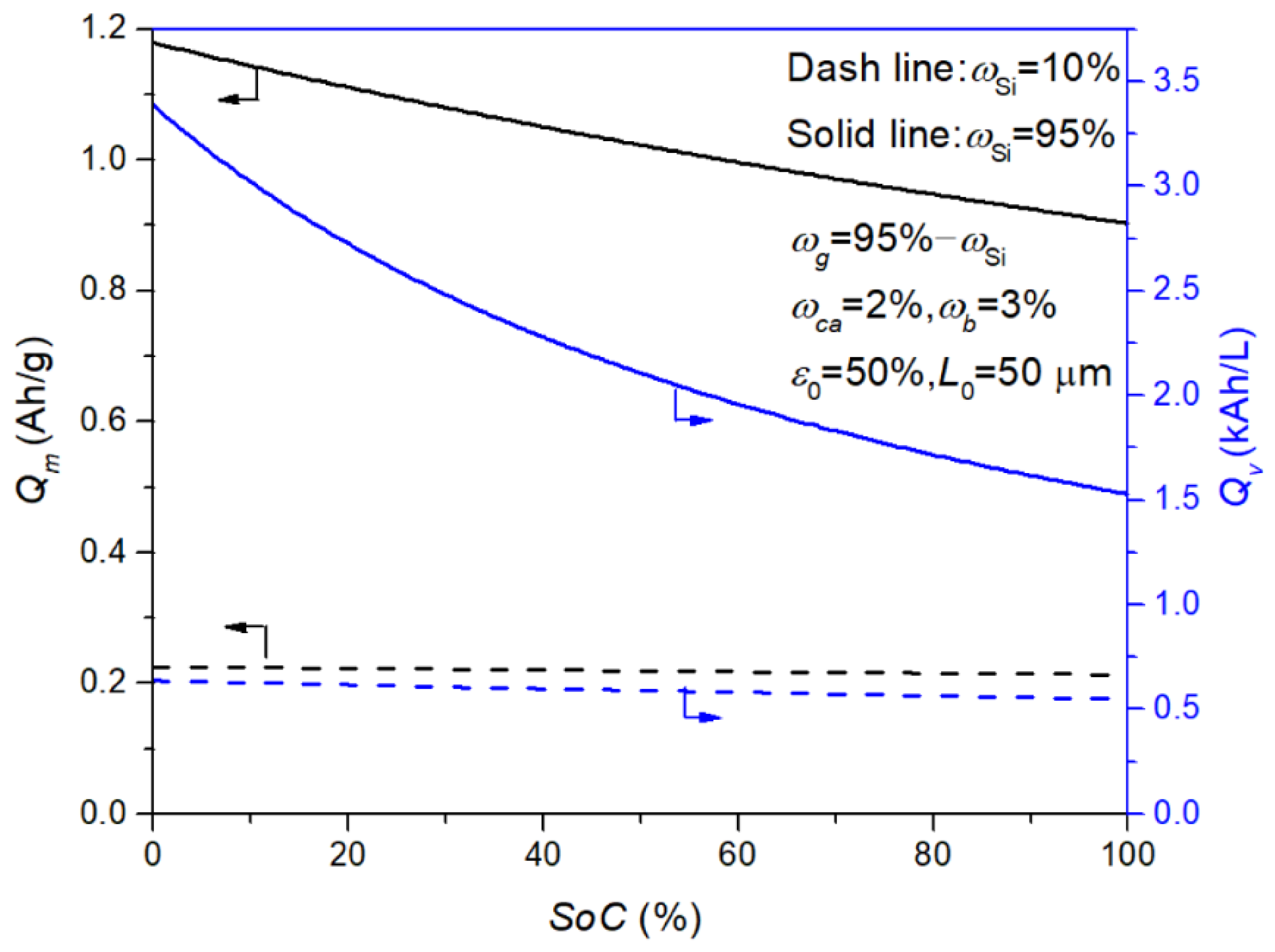
Figure 9.
The gravimetric and volumetric capacity as a function of SoC for Si-based electrodes with different (a) thicknesses and (b) initial porosities.
Figure 9.
The gravimetric and volumetric capacity as a function of SoC for Si-based electrodes with different (a) thicknesses and (b) initial porosities.

Table 1.
Nomenclature and physical properties used in this work.
| Symbol | Explanation | Value [Unit] |
|---|---|---|
| Mi | Molar mass of the element i (MLi = 6.94, MSi = 28.09, MC = 12.01) | [g mol−1] |
| ηi | volume expansion coefficient of the component i (ηSi = 3, ηg = 0.1, ηca = 0, ηb = 0) | [-] or [%] |
| ρi | Mass density of the component i (ρSi = 2.33, ρg = 2.20, ρca = 2.20, ρb = 1.80) | [g cm−3] |
| ωi | Mass fractions of the component i (ωSi = variable, ωg = 0.95 − ωSi, ωca = 2%, wb = 3%) | [-] or [%] |
| Qm,i | Theoretical specific capacity of the component i (Qm,Si = 3579, Qm,g = 370) | [mAh g−1] |
| Lcc | Thickness of the current collector (Lcc = 8) | [μm] |
Publisher’s Note: MDPI stays neutral with regard to jurisdictional claims in published maps and institutional affiliations. |
© 2022 by the authors. Licensee MDPI, Basel, Switzerland. This article is an open access article distributed under the terms and conditions of the Creative Commons Attribution (CC BY) license (https://creativecommons.org/licenses/by/4.0/).
Share and Cite
MDPI and ACS Style
Zhang, X.; Chen, J.; Bao, Y. Model-Based Investigations of Porous Si-Based Anodes for Lithium-Ion Batteries with Effects of Volume Changes. Energies 2022, 15, 8848. https://doi.org/10.3390/en15238848
AMA Style
Zhang X, Chen J, Bao Y. Model-Based Investigations of Porous Si-Based Anodes for Lithium-Ion Batteries with Effects of Volume Changes. Energies. 2022; 15(23):8848. https://doi.org/10.3390/en15238848
Chicago/Turabian StyleZhang, Xingyu, Jian Chen, and Yinhua Bao. 2022. "Model-Based Investigations of Porous Si-Based Anodes for Lithium-Ion Batteries with Effects of Volume Changes" Energies 15, no. 23: 8848. https://doi.org/10.3390/en15238848
Note that from the first issue of 2016, this journal uses article numbers instead of page numbers. See further details here.