
Research on Low Voltage Ride through Control of a Marine Photovoltaic Grid-Connected System Based on a Super Capacitor


1
School of Naval Architecture, Energy and Power Engineering, Wuhan University of Technology, Wuhan 430063, China
2
National Engineering Research Center for Water Transport Safety (WTS Center), Wuhan University of Technology, Wuhan 430063, China
3
Key Laboratory of Marine Power Engineering & Technology (Ministry of Transport), Wuhan University of Technology, Wuhan 430063, China
*
Author to whom correspondence should be addressed.
Energies 2022, 15(3), 1020; https://doi.org/10.3390/en15031020
Submission received: 30 November 2021
/
Revised: 22 January 2022
/
Accepted: 25 January 2022
/
Published: 29 January 2022
Abstract
:With the increase of photovoltaic penetration rate, the fluctuation of photovoltaic power generation affects the reliability of ship power grids. Marine PV grid-connected systems with high penetration rates should generally have a low voltage ride-through capability. In the present paper, a strategy in which super capacitors are applied for energy storage in a marine photovoltaic grid-connected system is proposed, and an inverter adopts independent decoupling control of active and reactive currents to improve the LVRT capability of photovoltaic grid-connected systems. In addition, a comprehensive control strategy is also designed to control the supercapacitor, to regulate the active power through the control method of the voltage outer loop and the current inner loop, in order to maintain the DC bus voltage stability. At the same time, the inverter can increase the reactive power output to support the grid voltage. The advantage of this system is in smoothing the power imbalance in a short time, enhancing the low voltage ride-through capability of the photovoltaic grid-connected system, improving the power quality, and ensuring the safety and stability of the ship’s power grid. MATLAB/Simulink were employed to establish a ro-ro ship super capacitor–marine photovoltaic grid-connected power system model and to carry out simulation experiments by setting the grid voltage drop. The results show that when the grid voltage drops, the inverter adjusts the distribution of active and reactive power. The power factor drops from 1 to 0.77, and the effective value of the voltage drop increases from 150 V to 156 V, which proves that this strategy effectively reduces the depth of the grid voltage drop and improves the low voltage ride-through capability of the photovoltaic grid-connected system.

1. Introduction
Marine photovoltaic technology has developed rapidly in recent years, and this trend is expected to continue, driven by continuous cost reductions and policy support [1,2,3]. Unlike land power grids, a ship power system is a special system with a very small capacity [4]. Integrating a photovoltaic system of the same capacity into a ship power grid system produces a greater photovoltaic penetration rate than in a land grid [5]. As the penetration rate of photovoltaics increases, several technical problems related to power quality will arise [6,7,8]. In addition to avoiding the influence of photovoltaic power fluctuation on the reliability of the ship power grid, it is important to strengthen the self-protection ability of the photovoltaic power generation system in the case of a short circuit fault of the ship power grid, to avoid more serious current impacts. Therefore, in order to ensure the safe and stable operation of marine power systems, a marine photovoltaic grid-connected system with high penetration rate should usually have a low voltage ride through capability.
A low voltage ride through capability was proposed in wind power grid connections, and has gradually been applied to the photovoltaic power generation field [9]. It means the photovoltaic power generation system can stay on the grid and continue to operate for a certain period of time when the grid voltage sags, and can provide a reactive power output to help with grid voltage recovery. In the land-use photovoltaic grid-connected specification, the low-voltage ride through curve is shown in Figure 1. When the voltage of the grid-connected point drops to 20% of the rated voltage, the photovoltaic grid-connected system should be able to ensure continuous grid-connected operation for one second. When the voltage of the grid-connected point can recover to 90% of the rated voltage within three seconds after falling, the photovoltaic power station should be able to ensure uninterrupted operation of the grid connection [10,11,12,13,14,15,16].
At present, a large number of studies have been carried out on the low voltage ride through of photovoltaic grid-connected systems. Sadeghkhani et al. proposed introducing a droop-based low voltage ride through strategy into grid-connected micro-grids and to implement it by using a controller with an interface voltage source converter (VSC) [18]. Similarly, Brandao et al. also considered a constant average active power control strategy for three-phase four-wire grid-connected inverters in a natural coordinate system [19]. On this basis, Shah et al. proposed a control algorithm based on an adaptive observer for the low voltage ride through capability of the two-stage grid-connected solar conversion systems (SECS). Adaptive observer technology was adopted to improve the power quality characteristics and estimate the fundamental component of the load current more accurately [20]. He et al. proposed a coordinated control scheme of low voltage ride through (LVRT) for an intelligent solar inverter, which can absorb more solar energy by controlling the DC link and photovoltaic unloading [21]. The above studies mainly focused on large and medium-sized land-based photovoltaic power stations, and rarely involved micro-grids, such as a ship power grid. However, a ship photovoltaic grid-connected system generally needs to be equipped with energy storage equipment to realize a smooth output of grid-connected power. In addition, energy quality can be improved and energy efficiency maximized through on-demand regulation of the energy supply. Energy storage systems have been put into commercial use as typical renewable energy and energy saving systems [22,23,24,25,26]. Ehsan Reihani et al. proposed the introduction of a battery energy storage system to analyze the effectiveness of BESS for peak clipping and smoothing the load curve of an actual circuit on Maui, Hawaii [27]. Iromi Ranaweera et al. addressed an energy management system for a PV system coupled with battery energy storage [28]. Therefore, energy storage equipment is used to absorb the unbalanced power between the DC side and AC side of the inverter during voltage sag, and the DC bus voltage is stabilized to enhance the LVRT capability of the photovoltaic grid-connected system, which does not increase the investment cost of the system, and also simplifies the control of the photovoltaic grid-connected system.
Among all the kinds of energy storage device, although lithium batteries have a high energy density, they are inferior to super capacitors in response speed, cycle life, and working efficiency [29]. A performance index comparison is shown in Table 1. The power of a photovoltaic grid-connected system is fed into the ship power station in real time, and an energy storage device is required to respond quickly and temporarily suppress the instantaneous power difference between the DC input side and the AC output side of the grid-connected inverter, which can reduce the instantaneous load volatility of the generator set operating in the network. Therefore, super capacitors have been widely used in this field [30].
In recent years, with the development of super capacitor technology, the advantages of super capacitors have become more obvious. Their fast response speed can make up for the intermittent fluctuation of photovoltaic output power [31]. Some scholars proposed the use of a voltage and current double closed-loop control strategy, to avoid the pumping of bus voltage by controlling the super capacitor and absorbing the DC bus feedback current into the ship electric propulsion system. Super capacitors and flywheel energy storage have also been introduced into the DC bus on the propulsion side of the ship electric propulsion system to improve the transient stability of the DC bus voltage and to improve the transient characteristics of the whole system. Super capacitors have not yet been applied in marine photovoltaic systems, while there have been attempts in land photovoltaic systems. Bertrand et al. analyzed the characteristics of super capacitors and battery energy storage, proposed a hybrid energy storage system, and established a simplified micro-grid model for verification [32]. Some scholars have adopted super capacitors as energy storage units in photovoltaic grid-connected systems to regulate the output power of photovoltaic power generation systems, established a bidirectional DC/DC converter model, and proposed a power and current double closed-loop control strategy to make the output power of inverters controllable.
Based on the above research, this paper proposes a low voltage ride through control strategy of a super capacitor, to avoid the danger caused by severe power quality problems of a ship power grid. During the voltage sag of the grid, the photovoltaic controller still works in the maximum power mode, and the super capacitor absorbs the excess energy, to realize the power balance between the direct side and the alternating side of the inverter, so as to ensure that the inverter will not be off-grid due to the output overcurrent protection. First, the paper introduces the structure of the marine photovoltaic grid-connected system. Second, a model and control strategy of the marine photovoltaic grid-connected system are determined. Then, a system simulation experiment and analysis are carried out. Finally, the analysis of the experimental results is summarized.
2. Structure of Marine Photovoltaic Grid-Connected System
The structure of the marine photovoltaic grid-connected system is shown in Figure 2. The power generated by the photovoltaic array is output after tracking the maximum power of the photovoltaic controller. The super capacitor is connected to the DC bus through a bidirectional DC/DC converter, which can be used as an energy storage device to store excess photoelectric energy. When voltage drops occur in the ship power system, the charge and discharge of the super capacitor can ensure the voltage stability of the DC bus and enhance the low voltage ride through of the inverter. The inverter converts the direct current into alternating current and then merges it into the main bus bar of the ship power station to supply power to the electric load together with the diesel generator.
3. Model and Control Strategy
A DC bus voltage regulation control strategy is designed into the bidirectional DC/DC converter charge–discharge control strategy of the supercapacitor control system. In Figure 3, the control principle of the marine photovoltaic grid-connected power system with enhanced low-voltage ride-through capability is shown.
3.1. Mathematical Model and Maximum Power Point Tracking of the Photovoltaic Cell
Photovoltaic cells convert light energy into electrical energy, according to the photovoltaic effect of semiconductor materials [33]. Belhachat and Larbes built a photovoltaic array model under local shadows, considering the influence of local shadows on photovoltaic output [34]. Zerhouni et al. took into account the internal resistance loss of the photovoltaic array and established a photovoltaic array model using the photovoltaic cell parameters under the standard conditions provided by the battery manufacturer [35]. Simulink provides a simulation model of photovoltaic cells, and an equivalent circuit diagram is shown in Figure 4. Ipv and Id are the photo-generated current and current flowing through diode, respectively, and Rs is the series resistance representing the internal loss in Figure 3. With the increase of service time, this value of Rs will increase, and the photovoltaic output power will decrease. Rsh is the side leakage resistance. U and I are the output voltage and current of the photovoltaic cell.
According to Kirchhoff’s current law:
The current expression of an ideal diode is
The output current of photovoltaic cells can be obtained by combining Formulas (1) and (2):
In this formula, q, I0, A, K, T are respectively the amount of charge (the value is 1.6 × 10⁻¹⁹), the diode reverse saturation current, the quality factor (the value is between 1–2), the Boltzmann constant (the value is 1.38 × 10⁻²³), and absolute temperature.
For photovoltaic cells, the value of the bypass resistance Rsh is very large, and the value of the series resistance Rs is very small, so the term (U + IRS)/Rsh is often ignored under ideal conditions. The output characteristics of photovoltaic cells in actual working conditions are mainly affected by irradiance and ambient temperature. Let , , , be the short-circuit current, open-circuit voltage, maximum power point current, and maximum power point voltage of photovoltaic cells under standard test conditions (irradiance S = 1000 W/m2, ambient temperature T = 25 °C, atmospheric quality AM = 1.5). Then Formula (3) is converted into:
In the process of use, it is necessary to consider the impact of non-standard environments, and modify the parameters such as photovoltaic voltage and current. The correction formula is as follows:
In this formula, , , , represent the corrected open-circuit voltage, short-circuit current, MPPT voltage, and maximum power point current. The typical values of a, b, and c in engineering are 0.0025 C−1, 0.5 m2/W, and 0.00288 C−1, respectively.
3.2. Photovoltaic Cell Simulation Model
According to a mathematical model of a photovoltaic cell derived in a previous article, MATLAB/Simulink was used to build a photovoltaic cell simulation model.
The simulation object of the photovoltaic cell module in this paper is the YLM series P-type monocrystalline silicon photovoltaic cell panel produced by Yingli Company, the model is YL285D-30b, and the parameters are listed in Table 2 under standard test conditions.
When the simulation sets the environment temperature T as constant at 25 °C and the irradiance S as 400 W/m2, 700 W/m2, and 1000 W/m2, respectively, the changes in the power and current of the photovoltaic array with voltage are as shown in Figure 5.
The simulation set the irradiance S to be constant at 1000 W/m2, and when the ambient temperature T is 10 °C, 25 °C, and 40 °C respectively, the changes in the power and current of the photovoltaic array with voltage are as shown in Figure 6.
The output characteristics of photovoltaic cells are affected by both ambient temperature and irradiance. As shown in Figure 4, when the ambient temperature is constant, with the increase of irradiance, the open circuit voltage of photovoltaic cells increases slightly, and the peak power and short-circuit current are obvious. As shown in Figure 5, when the irradiance is constant, as the ambient temperature rises, the short-circuit current of the photovoltaic cell gradually increases, while the open circuit voltage and maximum power gradually decrease, showing that the irradiance changes. The impact on photovoltaic output characteristics is greater than temperature changes. The output characteristic curve of the photovoltaic cell model built in this paper is basically the same as the actual photovoltaic cell panel characteristic curve, which can be used in the simulation experiment later.
In order to maximize the efficiency of photovoltaic power utilization, the photovoltaic controller needs to track its maximum power point tracking (MPPT). The essence of maximum power tracking is to match the load equivalent resistance with the photovoltaic internal resistance, by changing the on and off of the switch tube. The voltage level of the super capacitor and the DC bus is much lower than the MPPT voltage of the photovoltaic array. Therefore, the photovoltaic controller in this paper uses a BUCK step-down circuit and uses the variable step perturbation observation method to track the photovoltaic maximum power point.
3.3. Inverter Control Strategy
The output control of the inverter adopts the PQ control strategy, which can control the output power of the system by adjusting the magnitude and phase of the output current, so as to realize the transmission of all the generated power to the ship power grid. In essence, the strategy is the control of the active current and reactive current. Power output control can be achieved by tracking the current components id and iq on the dq axis to the reference current and through the current inner loop. According to instantaneous power theory, the inverter output reference current is
The mathematical model of the grid-connected inverter in the dq coordinate system is
In this equation, ud and uq are the grid voltage, and vd and vq are the inverter voltage control reference values. It can be seen from the equation that there is a strong coupling between the currents of the dq axis, and id and iq need to be decoupled in order to adjust them independently. The current decoupling control principle of id and iq is shown in Figure 7. PI adjustment is used to eliminate static errors, so that id and iq can track to and accurately. By introducing the current state feedback through feed-forward decoupling, independent control of the dq axis current can be achieved, and the feed-forward compensation will increase, so that the influence of grid voltage on the control system can be reduced.
When feed-forward decoupling is adopted, the control equation is
The reference voltages vd and vq obtained by current control are transformed by dp inverting to obtain the modulation signal Uref, and then sinusoidal pulse width modulation (SPWM) is applied to generate 6 PWM signals to control the IGBT of the inverter bridge as on or off. This is to realize the DC to three-phase AC inverter and power output.
3.4. Charge/Discharge Control of Super Capacitor
The structure of the energy storage device composed of a super capacitor and bidirectional DC/DC converter is shown in Figure 8. The DC bus is located on the high-voltage side, and the super capacitor is located on the low-voltage side. The equivalent model of the super capacitor is formed by the resistor Rc and capacitor Csc in series, in which Rc represents the energy consumption during charging and discharging of the super capacitor, and the bidirectional DC/DC converter adopts a bidirectional half-bridge structure.
The control of charging and discharging of the super capacitor is essentially the control of the operation mode of the bidirectional DC/DC converter. The bidirectional DC/DC converter adopts the control mode of the outer loop of the bus voltage and inner loop of the inductance current [36], and aims to stabilize the DC bus voltage. A control structure block diagram of the bidirectional DC/DC converter is shown in Figure 9. The DC bus voltage will basically keep stable when the power of the DC input side and AC output side of the inverter maintain a dynamic balance, while the power differences between the DC input side and AC output side will cause a change of bus voltage. The charging and discharging of the super capacitor controlled by the outer voltage loop can keep the DC bus voltage stable, thus maintaining a power balance between the input and output of the inverter. Considering the maximum current limit for charging and discharging of the super capacitor, the reference current of the inner loop obtained from the outer voltage loop is limited. Through the on or off of the IGBT driven by the PWM signal, the reference current will control the charging and discharging of the super capacitor, to keep the bus voltage stable.
The double closed-loop control structure, with the DC bus voltage control as the outer loop and the inductor current control as the inner loop, controls the bidirectional DC/DC converter to stabilize the DC bus voltage, as shown in Figure 10.
3.5. LVRT Control Strategy
According to the grid-connection criterion, the relationship between reactive current output and voltage sag depth is shown in Figure 11, in which U is set as the voltage of the photovoltaic connection point.
In Figure 8, the mathematical expression of reactive current output and power grid voltage sag depth is as follows:
The inverter operates at a unit power factor before the grid voltage sag, and its current is assumed to be is. When the voltage sags, the voltage sag depth is calculated by the voltage amplitude of the phase locking loop circuit. Then, the output of the reactive power reference current is calculated according to Equation (11).
During the grid voltage sag, if , the active reference current output by the inverter after the voltage sag is , if , then .
According to the equation of active reference current, when the voltage sags, only the output power factor of the current inverter needs to be adjusted, on condition that the inverter can provide sufficient reactive power output. If the reactive power output capacity of the inverter is insufficient, the active current output should be set to 0, so that all the reactive power can be output. No matter what method is adopted, the effective value of the power grid voltage sag will change, and so will the output power of the inverter. There will be unbalanced power between the DC side and the AC side of the inverter, resulting in voltage fluctuation at the DC bus. According to the aforementioned control mode of voltage outer loop and current inner loop, the control capacitor absorbs the unbalanced power, so as to realize low voltage ride through of the photovoltaic grid-connected system.
In this section, the concept of modularized modeling is adopted to establish the photovoltaic cell array and the MPPT control model based on the variable-step disturbance observation method; the power regulation device is composed of a super capacitor and bidirectional DC/DC converter, and the super capacitor adopts the equivalent circuit model. The two-way DC/DC converter is a two-way half-bridge structure; the PQ control strategy is used to control the output of the grid-connected inverter, and the supercapacitor power adjustment device adopts the double-loop control method of the power outer loop and the current inner loop to control the power. A sudden change in compensation or absorption makes the output power of the grid-connected inverter change slowly at a set rate; when the grid voltage drops, a low-voltage ride-through strategy based on supercapacitors is proposed, and the supercapacitor is used to absorb the unbalanced power during the grid voltage sag fault.
4. System Simulation and Analysis
4.1. Simulation Parameters Design
MATLAB/Simulink was used to establish a grid-connected power system model of a super capacitor marine photovoltaic system. The rated power of the main generator was 720 kW, the marine power grid frequency was 50 Hz, and the power grid phase voltage was 400 V. The photovoltaic array was composed of 18 series and 20 parallel arrays. Under standard test conditions, the peak power was 102.6 kW and the photovoltaic permeability was 14.25%. The simulation parameters of each part are set as shown in Table 3.
The output of active current and reactive current was controlled by controlling the active and reactive reference power of the inverter. RMS module obtained the effective value of the grid voltage for switching judgment. When the voltage sag was less than 10%, it entered the power leveling control, otherwise, it entered the low voltage crossing control.
4.2. Simulation Results Analysis
The change rate of the output power of the inverter was limited to 1 kW/s, and the change of irradiance is shown in Figure 12. The initial value of the irradiance was 500 W/m2, and it started to fluctuate randomly at 100 s. At 200 s, the value of the irradiance stabilized again at 500 W/m2.
The changes of the grid frequency and grid phase voltage of the marine photovoltaic grid-connected system are shown in Figure 13 and Figure 14.
According to Figure 13 and Figure 14, the grid frequency and phase voltage showed the same change state along with the random fluctuation of the irradiance. The fluctuation ranges of the grid frequency and the phase voltage were 0.4 Hz and 14 V, respectively. After the connection of the super capacitor, the grid frequency was maintained at 50 Hz and the phase voltage was maintained at 400 V, which effectively reduces the impact of the photovoltaic grid-connected system on the power quality of the ship power system.
It can be seen from Figure 15 that the grid voltage harmonics of the supercapacitor system were not connected to about 3%. After the supercapacitor was connected, the voltage harmonics were reduced to less than 1%, both of which are in line with the voltage harmonics in the CCS marine photovoltaic grid-connected guidelines. The requirement is that the wave content is less than 5%; the harmonics of the grid current that are not connected to the supercapacitor system exceeded the specification requirements of the current total harmonic content of less than 5% in the CCS marine photovoltaic grid-connected guidelines, and after the supercapacitor was connected, the current harmonics dropped to about 1%, which meets the specification requirements.
In order to verify the low voltage ride through strategy of the photovoltaic grid-connected system based on a super capacitor proposed above, the photovoltaic array was set to work under standard test conditions (irradiance S = 1000 W/m2, ambient temperature T = 25 °C) in the example simulation. The voltage variation curve of the marine power grid is shown in Figure 16. Three-phase symmetric voltage sag occurred at 0.5 s with a 35% sag depth, and it returned to normal at 0.8 s. The simulation results are shown in Figure 17, Figure 18, Figure 19, Figure 20, Figure 21 and Figure 22.
The following are concluded from Figure 17, Figure 18, Figure 19, Figure 20, Figure 21 and Figure 22:
- (1)
- In case of grid voltage sag, it can be seen from Figure 20a and Figure 21 that the inverter operates under unit power factor without LVRT control in grid-connected system and does not output reactive power, but the active output power drops slightly due to voltage sag. As shown in Figure 17a, Figure 18a and Figure 20a, as the photovoltaic array continues to work at the maximum power state, an imbalance between the input power and output power appears on the DC bus side, and the power difference acts on the DC bus, and the DC bus voltage presents a rapid upward trend. The DC bus voltage increases because the input power of the inverter is greater than the output power. In order to ensure the power balance between the DC input and the AC output of the inverter, the output current of the inverter will increase to 1.4 pu, which exceeds the rated operating current and causes the inverter to be off-gird due to overcurrent protection, thus increasing the fault range.
- (2)
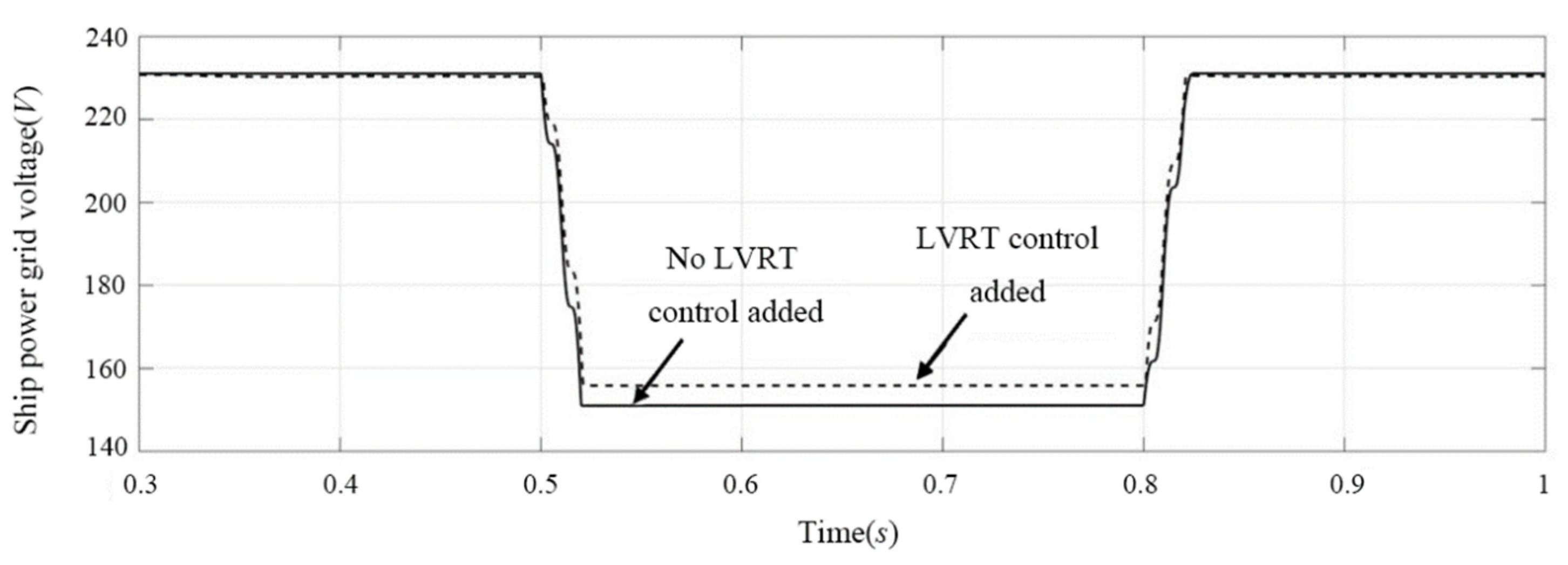
- With LVRT control, the photovoltaic controller still operates in MPPT mode during voltage sag. According to Figure 17b and Figure 18b, in order to prevent the inverter from being off-grid due to output overcurrent during voltage sag, the inverter reduces the active power output and its output current is always less than 1.1 pu. During the fault period, the super capacitor absorbs the energy difference between the inverter and the controller, so that the DC bus voltage remains stable. The dynamic and static response is ideal, with the overshoot of the DC bus less than 5%, the adjustment time less than 0.1 s, and the steady-state voltage basically remaining at 380 V. It can be seen from Figure 19 and Figure 22 that the inverter adjusts the distribution of active and reactive power when the grid voltage sags, with the power factor decreasing from 1 to 0.77 and the voltage sag increasing from 150 V to 156 V. The control strategy can absorb excess photovoltaic energy through the super capacitor adjustment system, greatly reduce the voltage rise of the DC bus of the photovoltaic power generation system, and maintain the grid-connected current below the limit current value. After the fault is removed, the marine diesel/photovoltaic grid-connected power system will quickly return to the normal working state, enhancing the low voltage ride-through capability of the system.
5. Conclusions
In this paper, the off-grid protection of a marine high permeability photovoltaic grid-connected system under voltage sag is studied. A super capacitor can be used to suppress the unbalanced power of the DC side of the inverter in a short period of time, enhance the low voltage ride through ability of the photovoltaic grid-connected system, improve the power quality, and ensure the safety and stability of the marine power grid. The main conclusions are as follows:
- (1)
- The use of super capacitors for ship energy storage can keep the DC bus voltage stable and reduce the power injected into the photovoltaic inverter.
- (2)
- The inverter can realize the independent control of dq axis current. At the same time, the feedforward compensation of the grid voltage is added, which reduces the influence of the grid voltage on the control system.
- (3)
- When the ship grid voltage fluctuates, the photovoltaic grid-connected system control strategy automatically adjusts the distribution of active power and reactive power to help restore the grid voltage.
Author Contributions
S.W.: contributed to the conception of the study; performed the experiment; performed the data analyses and wrote the manuscript; X.T.: contributed to the conception of the study; contributed significantly to the analysis and manuscript preparation; X.L.: performed the experiment; C.X.: helped perform the analysis with constructive discussions. All authors have read and agreed to the published version of the manuscript.
Funding
This research was supported by the Hubei Provincial Key R&D Project (International Cooperation Field) of Hubei Provincial Department of Science and Technology (No.2020BHB001) and the National Natural Science Foundation of China (No. 51806164).
Institutional Review Board Statement
Not applicable.
Informed Consent Statement
Not applicable.
Data Availability Statement
All data generated or analyzed in this study are included in the article.
Acknowledgments
The authors thank Wuhan University of Technology for providing experimental equipment and guidance on the article.
Conflicts of Interest
The authors declare no conflict of interest.
Nomenclature
| Ipv,Vpv | PV source output voltage andcurrent | Reference current | |
| Id | Current flowing through the diode | is | Current of the inverter operating at unity power factor |
| Rs | Series resistance characterizing internal loss | C1 | Photovoltaic controller capacitor |
| Rsh | Bypass leakage resistance | L1 | Photovoltaic controller inductance |
| U | PV cell output voltage | D | Photovoltaic controller duty cycle |
| I | PV cell output current | Cdc | Photovoltaic controller DC bus capacitor |
| id | Stator d-axis current component | C2 | Bidirectional DC/DC converter capacitor |
| iq | Stator q-axis current component | L2 | Bidirectional DC/DC converter inductor |
| ud | Grid d-axis voltage | Kp1 | Voltage outer loop proportional coefficient |
| uq | Power grid q axis voltage | Ki1 | Integral coefficient of voltage outer loop |
| vd | Stator d-axis reference voltage | Kp2 | Current inner loop proportional coefficient |
| vq | Stator q-axis reference voltage | Ki2 | Current inner loop integral coefficient |
| Stator d-axis reference current | C3 | Inverter filter capacitor | |
| Stator q-axis reference current | L3 | Inverter filter inductor | |
| Uref | Modulated signal | Kp3 | Power outer ring proportional coefficient |
| Rc | Super capacitor model equivalent resistance | Ki3 | Power outer loop integral coefficient |
| Csc | Equivalent capacitance of the supercapacitor model |
References
- Crago, C.L.; Koegler, E. Drivers of growth in commercial-scale solar PV capacity. Energy Policy 2018, 120, 481–491. [Google Scholar] [CrossRef]
- Bolinger, M.; Seel, J.; Robson, D. Utility-Scale Solar: Empirical Trends in Project Technology, Cost, Performance, and PPA Pricing in the United States-2019 Edition; Lawrence Berkeley National Laboratory: Berkeley, CA, USA, 2019. [Google Scholar]
- Barbose, G.; Darghouth, N. Tracking the Sun: Pricing and Design Trends for Distributed Photovoltaic Systems in the United States-2019 Edition; Lawrence Berkeley National Laboratory: Berkeley, CA, USA, 2019. [Google Scholar]
- Hebner, R.E.; Uriarte, F.M.; Kwasinski, A.; Gattozzi, A.L.; Estes, H.B.; Anwar, A.; Cairoli, P.; Dougal, R.A.; Feng, X.; Chou, H.-M. Technical cross- fertilization between ter-restrial microgrids and ship power systems. J. Mod. Power Syst. Clean Energy 2016, 4, 161–179. [Google Scholar] [CrossRef] [Green Version]
- Liu, H.; Zhang, Q.; Qi, X.; Han, Y.; Lu, F. Estimation of PV output power in moving and rocking hybrid energy marine ships. Appl. Energy 2017, 204, 362–372. [Google Scholar] [CrossRef]
- ElNozahy, M.; Salama, M. Technical impacts of grid-connected photovoltaic systems on electrical networks—A review. J. Renew. Sustain. Energy 2013, 5, 032702. [Google Scholar] [CrossRef]
- Baggini, A. Handbook of Power Quality; John Wiely & Sons: Hoboken, NJ, USA, 2008. [Google Scholar]
- Hou, Y.; Magnusson, J.; Engdahl, G.; Liljestrand, L. Impact on voltage rise of PV generation in future swedish urban areas with high PV penetration. In Proceedings of the 2014 IEEE International Energy Conference (ENERGYCON), Cavtat, Croatia, 13–16 May 2014; pp. 904–911. [Google Scholar]
- Mehrdad, T.H.; Muttaqi, K.M. Low Voltage Ride through of Wind Energy Systems; Springer: Singapore, 2017; pp. 6–15. [Google Scholar]
- Camacho, A.; Castilla, M.; Miret, J.; Borrell, A.; de Vicuña, L.G. Active and reactive power strategies with peak current limitation for distributed generation inverters during unbalanced grid faults. IEEE Trans. Ind. Electron. 2015, 62, 1515–1525. [Google Scholar] [CrossRef] [Green Version]
- Luna, A.; Rocabert, J.; Candela, J.I. Grid voltage synchronization for distributed generation systems under grid fault conditions. IEEE Trans. Ind. Appl. 2015, 51, 3414–3425. [Google Scholar] [CrossRef]
- Calle-Prado, A.; Alepuz, S.; Bordonau, J.; Nicolas-Apruzzese, J.; Cortés, P.; Rodriguez, J. Model predictive current control of grid-connected neutral point clamped converters to meet low-voltage ride-through requirements. IEEE Trans. Ind. Electron. 2015, 62, 1503–1514. [Google Scholar] [CrossRef] [Green Version]
- Saadat, N.; Choi, S.S.; Vilathgamuwa, D.M. A Statistical evaluation of the capability of distributed renewable generator energy storage system in providing load low-voltage ride-through. IEEE Trans. Power Deliv. 2015, 30, 1128–1136. [Google Scholar] [CrossRef]
- Chou, S.-F.; Lee, C.-T.; Ko, H.-C.; Cheng, P.-T. A low-voltage ride-through method with transformer flux compensation capability of renewable power grid-side converters. IEEE Trans. Power Electron. 2014, 29, 1710–1719. [Google Scholar] [CrossRef]
- Meyer, R.; Zlotnik, A.; Mertens, A. Fault ride-through control of medium-voltage converters with LCL filter in distributed generation systems. IEEE Trans. Ind. 2014, 50, 3448–3456. [Google Scholar] [CrossRef]
- Guo, X.; Zhang, X.; Wang, B.; Wu, W.; Guerrero, J.M. Asymmetrical grid fault ride-through strategy of three-phase grid-connected inverter considering network impedance impact in low-voltage grid. IEEE Trans. Power Electron. 2014, 29, 1064–1068. [Google Scholar] [CrossRef] [Green Version]
- Liu, Y.; Tian, L. Research on low voltage ride through technology of grid-connected photovoltaic system. In Proceedings of the 2016 International Conference on Smart Grid and Clean Energy Technologies (ICSGCE), Chengdu, China, 19–22 October 2016. [Google Scholar]
- Sadeghkhani, I.; Golshan, M.E.H.; Mehrizi-Sani, A.; Guerrero, J.M. Low-voltage ride-through of a droop-based three-phase four-wire grid-connected microgrid. IET Gener. Transm. Distrib. 2018, 12, 1906–1914. [Google Scholar] [CrossRef]
- Brandao, D.I.; Mendes, F.E.; Ferreira, R.V.; Silva, S.M.; Pires, I.A. Active and reactive power injection strategies for three-phase four-wire inverters during symmetrical/asymmetrical voltage sags. IEEE Trans. Ind. Appl. 2019, 55, 2347–2355. [Google Scholar] [CrossRef]
- Mojallal, A.; Lotfifard, S. Enhancement of grid connected PV arrays fault ride through and post fault recovery performance. IEEE Trans. Smart Grid 2019, 10, 546–555. [Google Scholar] [CrossRef]
- Yu, H.E.; Xu, Z.; Li, Y. A novel control scheme for enhancing low voltage ride through capability of solar generation. In Proceedings of the 2017 China International Electrical and Energy Conference (CIEEC), Beijing, China, 25–27 October 2017; pp. 129–134. [Google Scholar]
- Jeong, H.G.; Ro, H.S.; Lee, K.B. An improved maximum power point tracking method for wind power systems. Energies 2012, 5, 1339–1354. [Google Scholar] [CrossRef] [Green Version]
- Lee, J.S.; Lee, K.B. New modulation techniques for a leakage current reduction and a neutral-point voltage balance in transformerless photovoltaic systems using a three-level inverter. IEEE Trans. Power Electron. 2014, 29, 1720–1732. [Google Scholar] [CrossRef]
- Espi, J.M.; Castello, J. Wind turbine generation system with optimized DC-link design and control. IEEE Trans. Ind. Electron. 2013, 60, 919–929. [Google Scholar] [CrossRef]
- Kim, M.K. Optimal control and operation strategy for wind turbines contributing to grid primary frequency regulation. Appl. Sci. 2017, 7, 927. [Google Scholar] [CrossRef]
- Vazquez, S.; Lukic, S.M.; Galvan, E.; Franquelo, L.G.; Carrasco, J.M. Energy storage systems for transport and grid applications. IEEE Trans. Ind. Electron. 2010, 57, 3881–3895. [Google Scholar] [CrossRef] [Green Version]
- Ranaweera, I.; Midtgard, O.M. Optimization of operational cost for a grid-supporting PV system with battery storage. Renew. Energy 2016, 88, 262–272. [Google Scholar] [CrossRef]
- Reihani, E.; Motalleb, M.; Ghorbani, R.; Saoud, L.S. Load peak shaving and power smoothing of a distribution grid with high renewable energy penetration. Renew. Energy 2016, 86, 1372–1379. [Google Scholar] [CrossRef] [Green Version]
- Lai, C.S.; Jia, Y.; Lai, L.L.; Xu, Z.; McCulloch, M.D.; Wong, K.P. A comprehensive review on large-scale photovoltaic system with applications of electrical energy storage. Renew. Sustain. Energy Rev. 2017, 78, 439–451. [Google Scholar] [CrossRef]
- Salminen, J.; Kallio, T.; Omar, N.; Van den Bossche, P.; Van Mierlo, J.; Gualous, H. Transport energy lithium ion batteries. In Future Energy, 2nd ed.; Elsevier: Amsterdam, The Netherlands, 2014; pp. 291–309. [Google Scholar]
- Sato, T. Science, Technology and Advanced Application of Super-Capacitors; Springer: London, UK, 2019. [Google Scholar]
- Li, J.; Cornelusse, B.; Vanderbemden, P.; Ernst, D. A SC/battery hybrid energy storage system in the microgrid. Energy Procedia 2017, 142, 3697–3702. [Google Scholar] [CrossRef]
- Paternoster, G.; Zanuccoli, M.; Bellutti, P.; Ferrario, L.; Ficorella, F.; Fiegna, C.; Magnone, P.; Mattedi, F.; Sangiorgi, E. Fabrication, characterization and modeling of a silicon solar cell optimized for concentrated photovoltaic applications. Sol. Energy Mater. Sol. Cells 2015, 134, 407–416. [Google Scholar] [CrossRef]
- Belhachat, F.; Larbes, C. Modeling, analysis and comparison of solar photovoltaic array configurations under partial shading conditions. Sol. Energy 2015, 120, 399–418. [Google Scholar] [CrossRef]
- Femia, N.; Petrone, G.; Spagnuolo, G.; Vitelli, M. Power Electronics and Control Techniques for Maximum Energy Harvesting in Photovoltaic Systems; CRC Press: Boca Raton, FL, USA, 2017. [Google Scholar]
- Khan, M.J.; Mathew, L. Different kinds of maximum power point tracking control method for photovoltaic systems: A review. Arch. Comput. Methods Eng. 2017, 24, 855–867. [Google Scholar] [CrossRef]
Figure 1.
Low voltage ride through curve [17].
Figure 1.
Low voltage ride through curve [17].
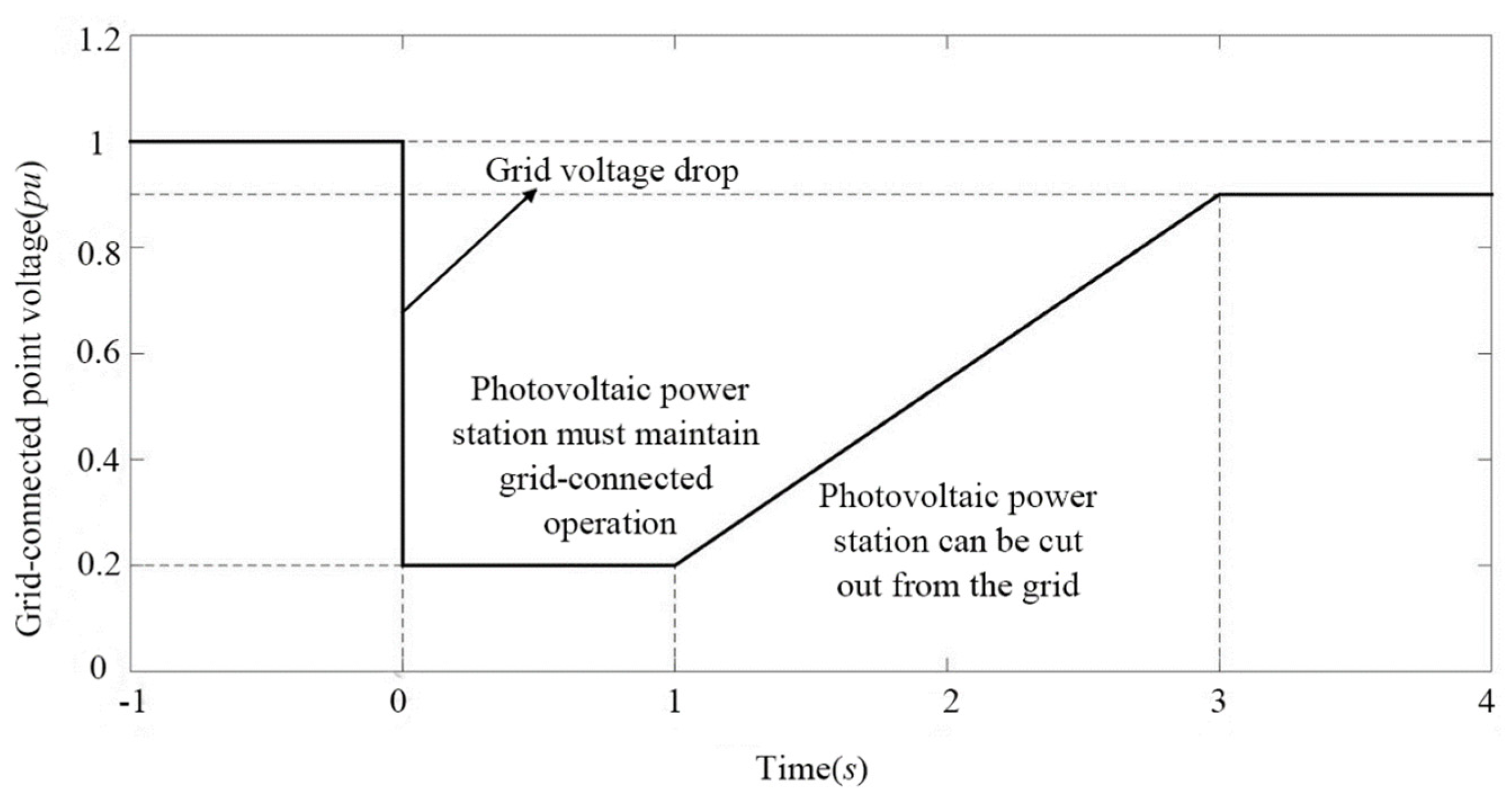
Figure 2.
The structure of the marine photovoltaic grid-connected system.
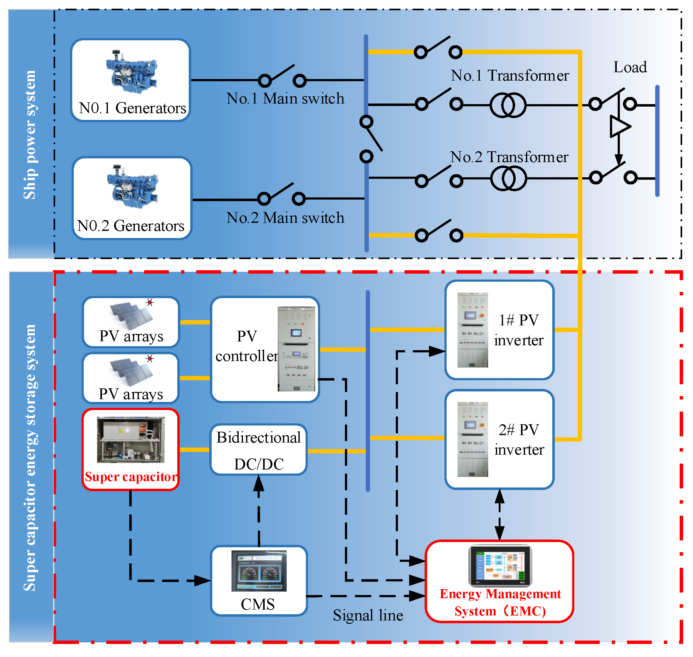
Figure 3.
Schematic diagram of the control of the marine photovoltaic grid-connected power system.
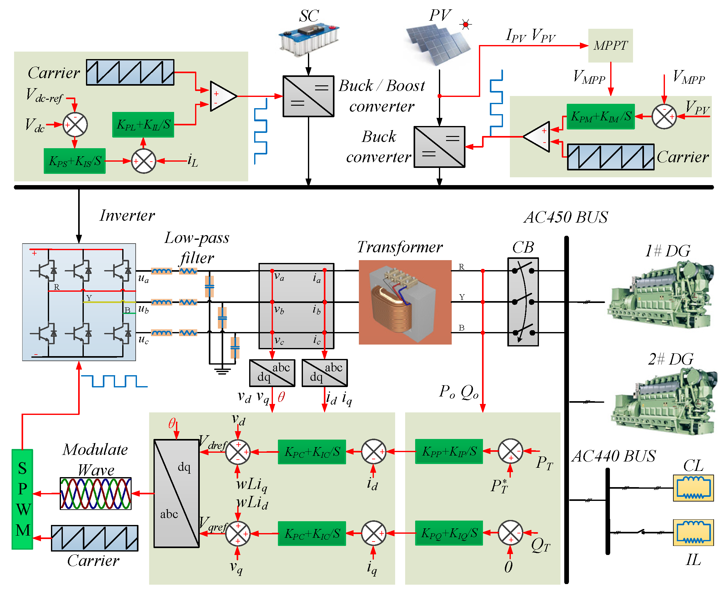
Figure 4.
Photovoltaic cell equivalent circuit.
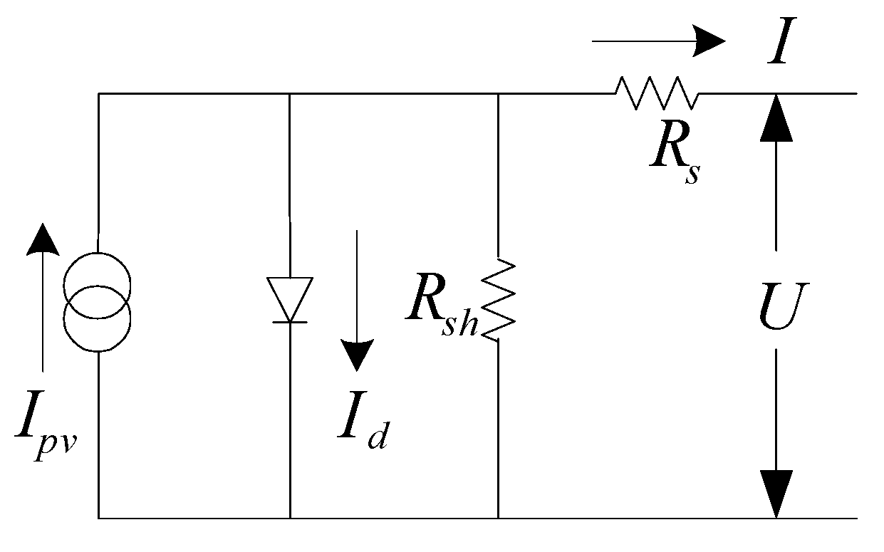
Figure 5.
Irradiance variation characteristic curve. (a) I-U curve, (b) P-U curve.
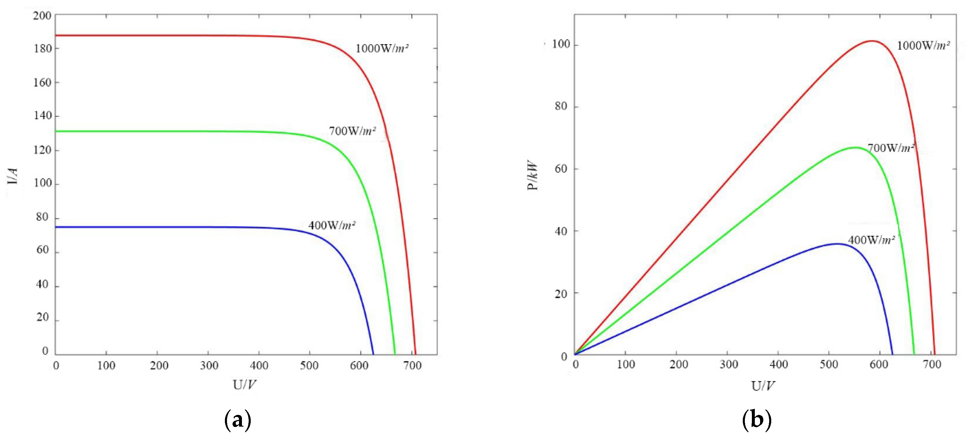
Figure 6.
Temperature change characteristic curve. (a) I-U curve, (b) P-U curve.
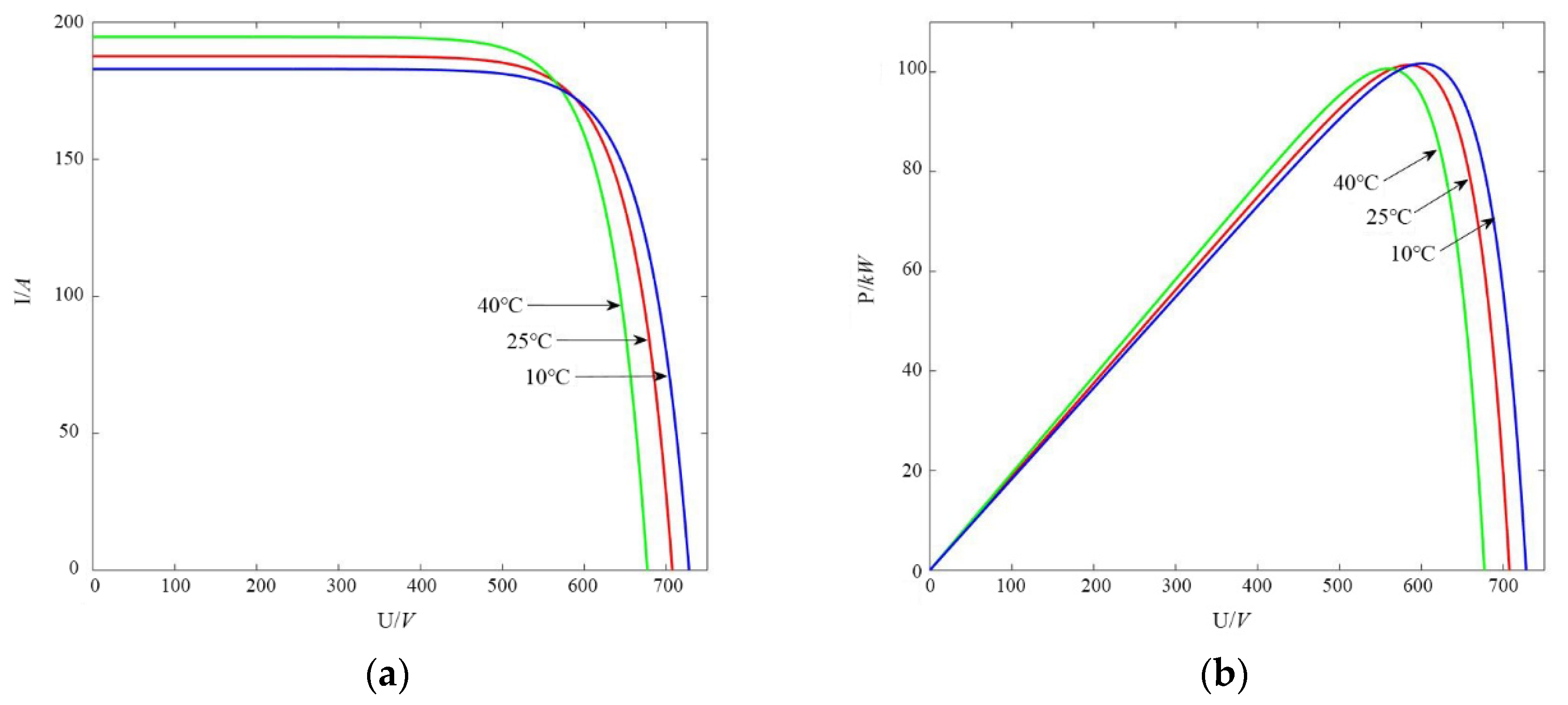
Figure 7.
Current control block diagram.
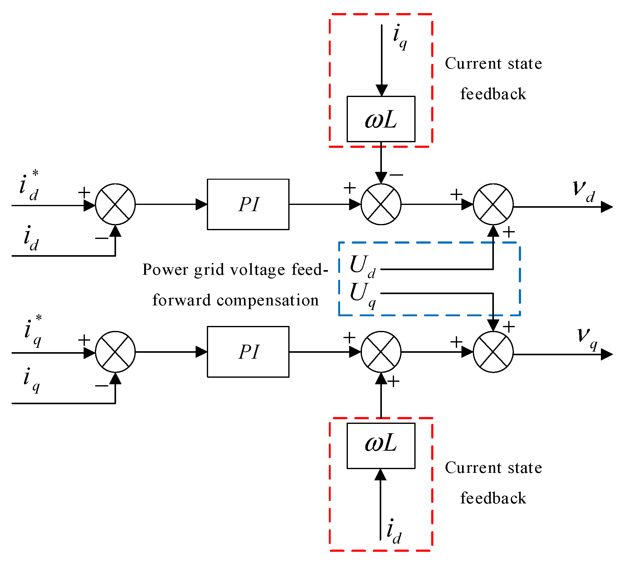
Figure 8.
Topological structure diagram of the super capacitor energy storage device.
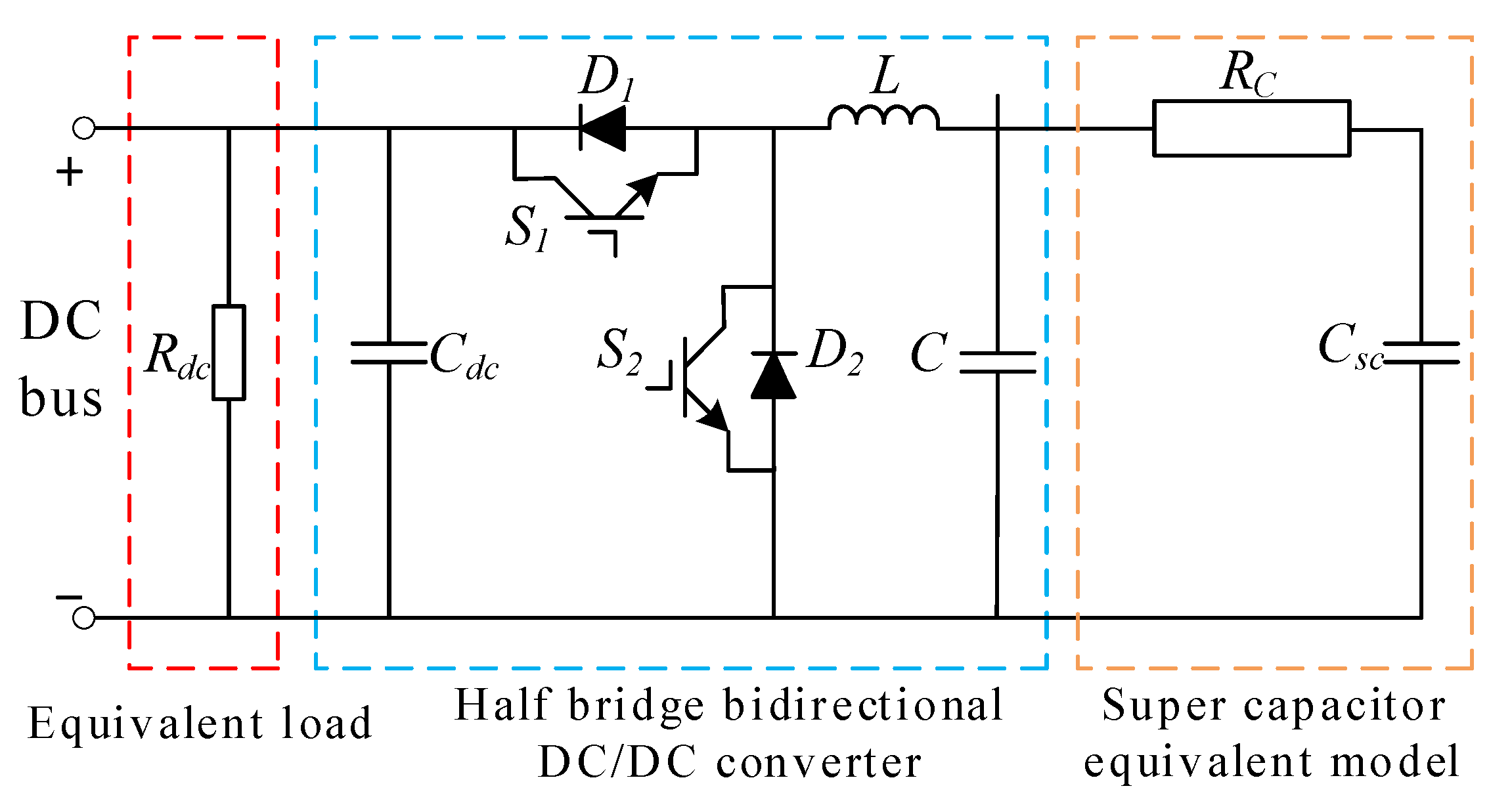
Figure 9.
Voltage outer loop, current inner loop control.
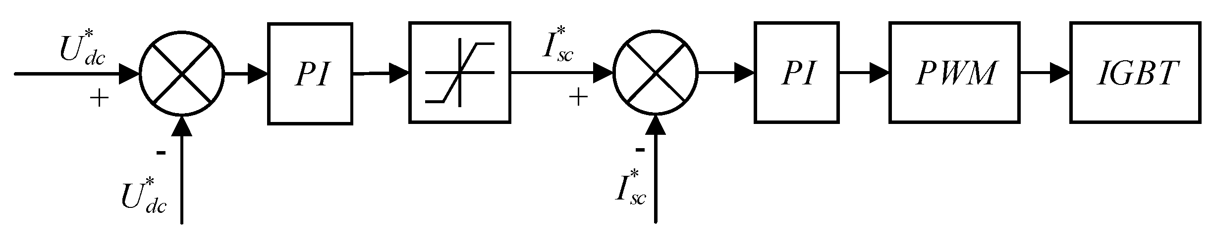
Figure 10.
SC charging and discharging control strategy based on stabilizing the DC bus voltage.
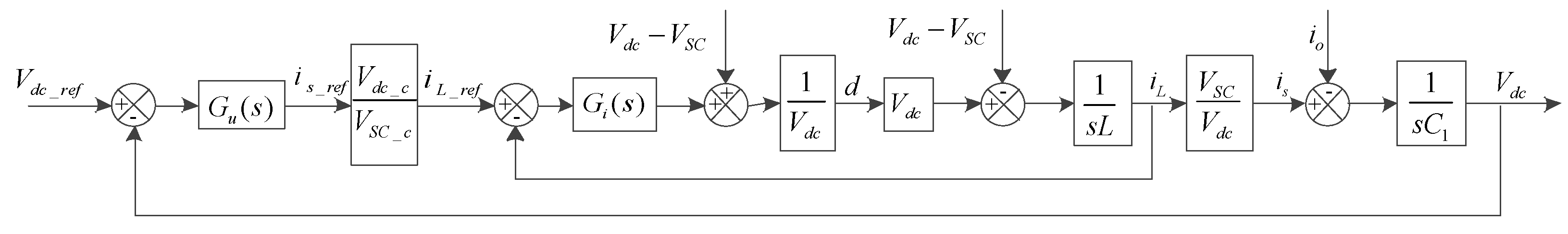
Figure 11.
Relation curve between reactive current output and grid voltage drop depth.

Figure 12.
The change of irradiance.
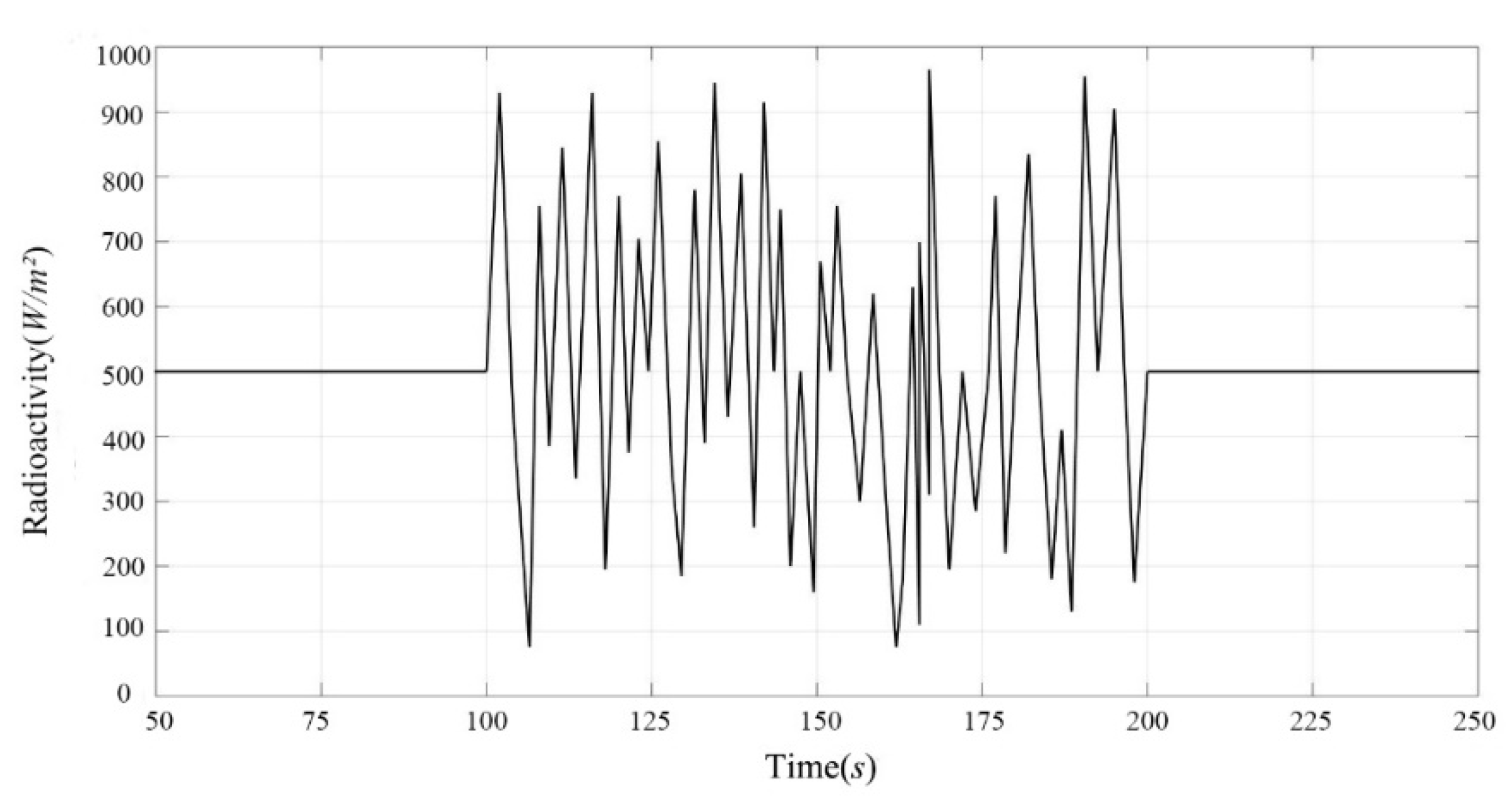
Figure 13.
The frequency changes of the ship’s power grid. (a) Not connected to a super capacitor, (b) Connected to a super capacitor.
Figure 13.
The frequency changes of the ship’s power grid. (a) Not connected to a super capacitor, (b) Connected to a super capacitor.

Figure 14.
The Phase voltage change of ship power grid. (a) Not connected to a super capacitor, (b) Connected to a super capacitor.
Figure 14.
The Phase voltage change of ship power grid. (a) Not connected to a super capacitor, (b) Connected to a super capacitor.
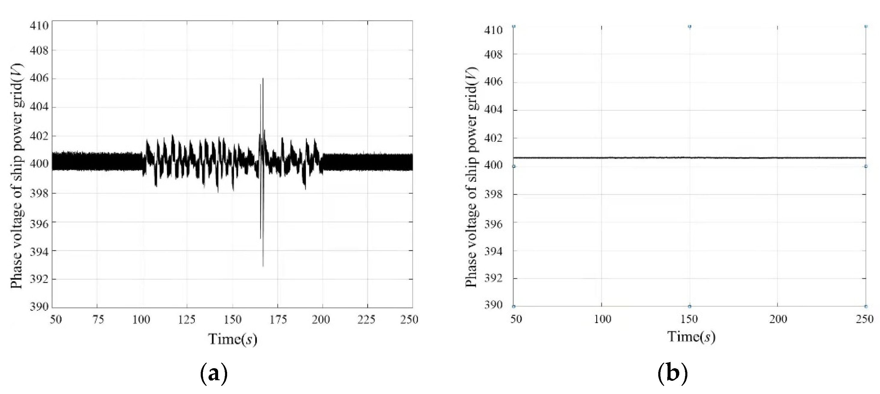
Figure 15.
Grid voltage harmonic content.
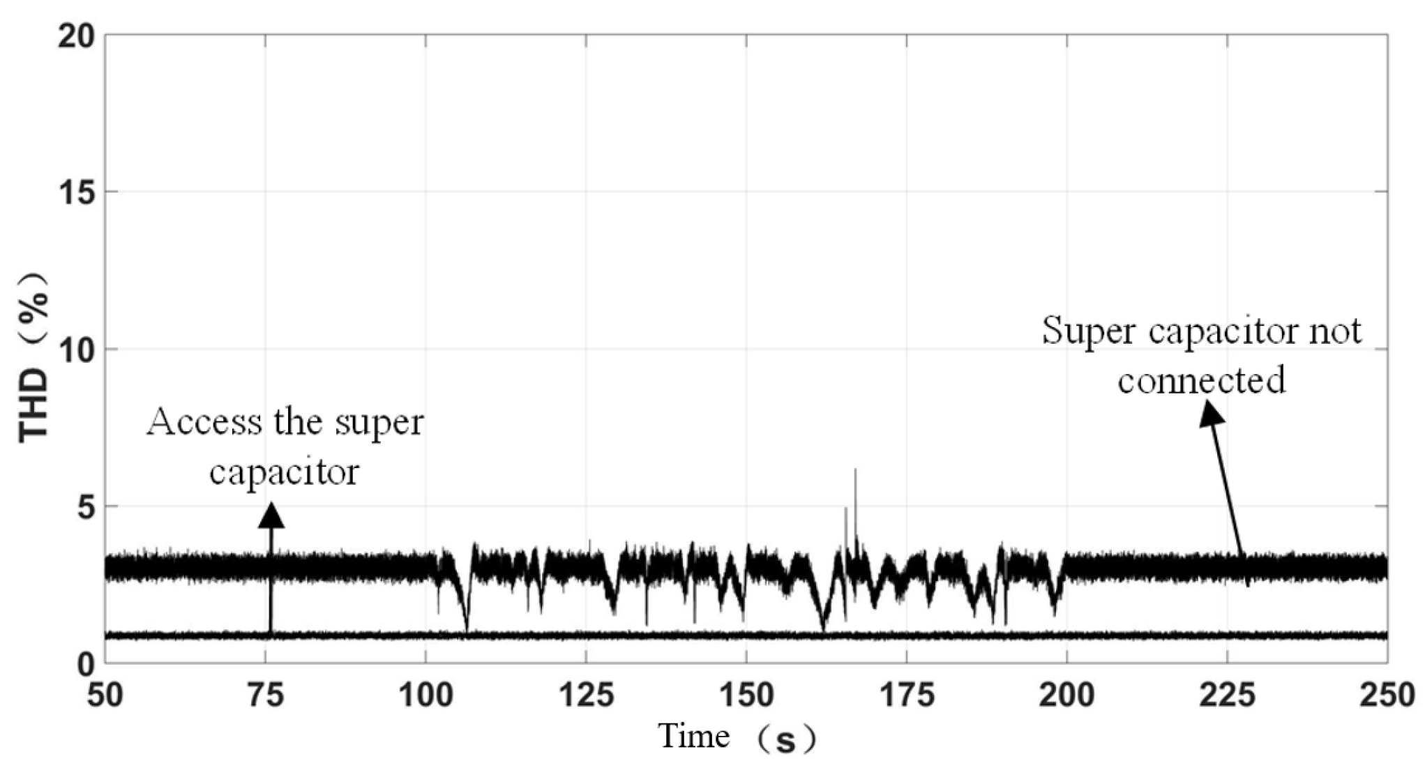
Figure 16.
Ship power grid voltage curve.

Figure 17.
DC bus voltage controlled by LVRT. (a) No LVRT control added, (b) LVRT control added.

Figure 18.
Inverter output current curve. (a) No LVRT control added, (b) LVRT control added.


Figure 19.
Inverter output current pu curve.
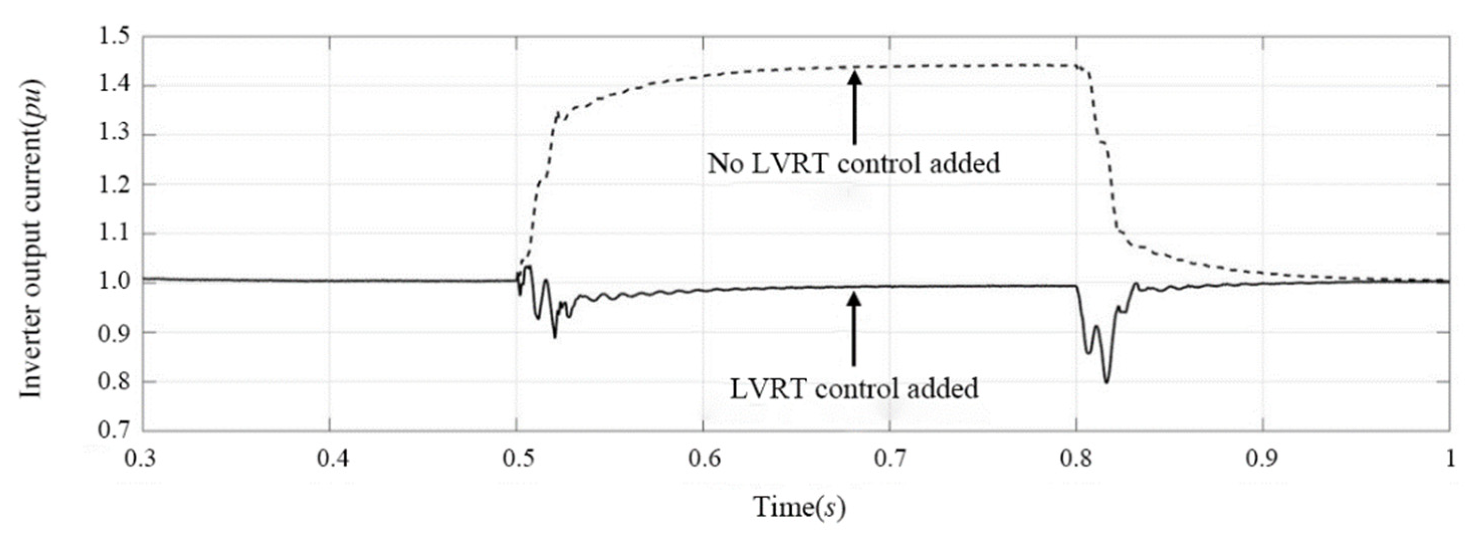
Figure 20.
Power curve. (a) No LVRT control added, (b) LVRT control added.
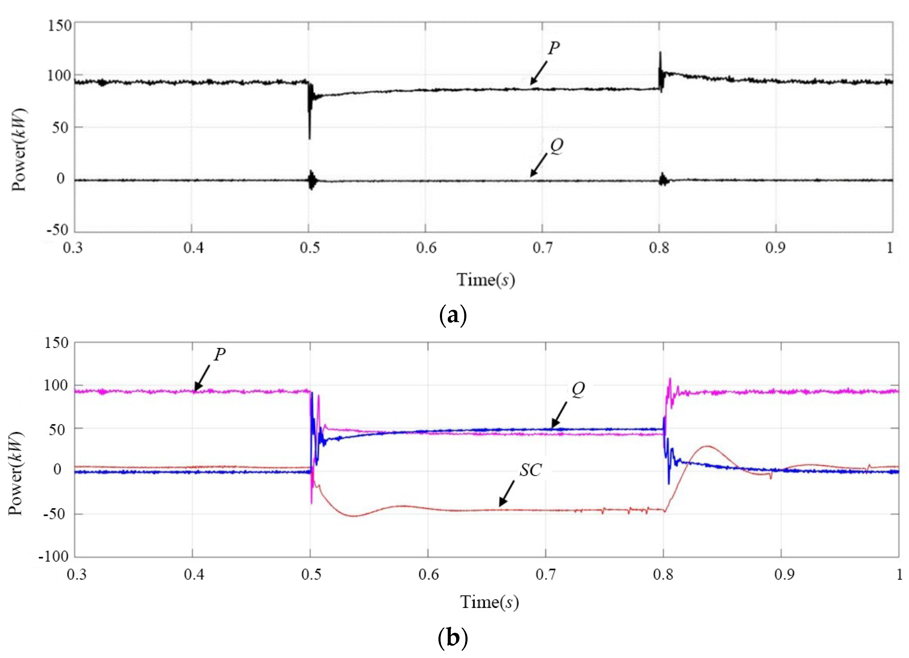
Figure 21.
Power factor curve.
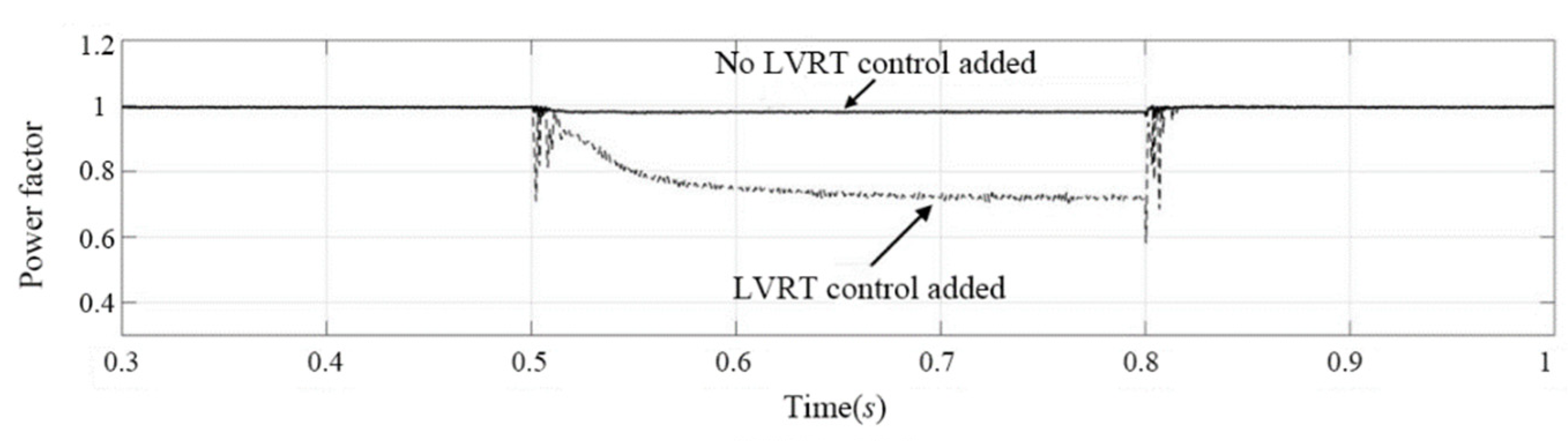
Figure 22.
The effective value curve of the ship power grid voltage.

Table 1.
Comparison of performance indicators of energy storage components.
| Performance Comparison | Charging Time/(s) | Discharge Time/(s) | Power Density/(W/kg) | Charge and Discharge Efficiency/(%) | Product Maintenance | Service Life/(Years) |
|---|---|---|---|---|---|---|
| Lithium battery | (3.6~18) × 103 | (1.08~10.8) × 103 | <103 | 70–85 | high cost | 4–6 |
| Super capacitor | 0.3~30 | 0.3~30 | <104 | 85–98 | low cost | 10–15 |
Table 2.
PV module parameters.
| String Relationship | Total Power/kW | Open Circuit Voltage/V | Short Circuit Current/A | Peak Voltage/V | Peak Current/A |
|---|---|---|---|---|---|
| 18 series 20 parallel | 102.7 | 712.8 | 188.2 | 570.6 | 180 |
Table 3.
Simulation parameters.
| Equipment | Parameter | Value | Unit |
|---|---|---|---|
| Photovoltaic controller | C1 | 1.7 | mF |
| L1 | 16 | µH | |
| D | 0.1% | - | |
| Cdc | 10 | mF | |
| Bidirectional DC/DC converter | IGTT switching frequency | 4 | kHz |
| C2 | 1 | mF | |
| L2 | 3 | mH | |
| Kp1 | 0.8 | - | |
| Ki1 | 100 | - | |
| Kp2 | 0.2 | - | |
| Ki2 | 30 | - | |
| Super capacitor | Operating voltage range | 240~300 | VDC |
| Energy storage capacity | 6 | kWh | |
| Maximum output current limit | 400 | A | |
| Inverter | C3 | 20 | µF |
| L3 | 0.5 | mH | |
| Kp3 | 0.01 | - | |
| Ki3 | 3 | - | |
| Kp2 | 120 | - | |
| Ki2 | 5 | - |
Publisher’s Note: MDPI stays neutral with regard to jurisdictional claims in published maps and institutional affiliations. |
© 2022 by the authors. Licensee MDPI, Basel, Switzerland. This article is an open access article distributed under the terms and conditions of the Creative Commons Attribution (CC BY) license (https://creativecommons.org/licenses/by/4.0/).
Share and Cite
MDPI and ACS Style
Wang, S.; Tang, X.; Liu, X.; Xu, C. Research on Low Voltage Ride through Control of a Marine Photovoltaic Grid-Connected System Based on a Super Capacitor. Energies 2022, 15, 1020. https://doi.org/10.3390/en15031020
AMA Style
Wang S, Tang X, Liu X, Xu C. Research on Low Voltage Ride through Control of a Marine Photovoltaic Grid-Connected System Based on a Super Capacitor. Energies. 2022; 15(3):1020. https://doi.org/10.3390/en15031020
Chicago/Turabian StyleWang, Shihao, Xujing Tang, Xionghang Liu, and Chen Xu. 2022. "Research on Low Voltage Ride through Control of a Marine Photovoltaic Grid-Connected System Based on a Super Capacitor" Energies 15, no. 3: 1020. https://doi.org/10.3390/en15031020
Note that from the first issue of 2016, this journal uses article numbers instead of page numbers. See further details here.