1. Introduction
Ejectors, being simple and safe devices without the need for service during operation, have found wide use in water heating systems.
For the operation of the ejector, at the connection point of the ejector thermal substation of the water–water type, there must be a certain pressure difference between the supply network and the return network of 150 kPa (15 mH2O), therefore, in the ejector nozzle a certain speed of water must be achieved, which results in the creation of a certain vacuum in the suction pipe and thus enables the mixing of a quantity of water from the return network with the water of the supply network. This amount of the mixed water then goes to the thermal consumer. If the pressure difference between the supply and return networks is low, in order to mix the return network water with the supply network water a pump must be used.
Many studies have been done regarding ejectors, some of which are presented below.
In literature [
1,
2] by prof. J.J. Sokolov are provided theoretical reviews, among others, the characteristics of the ejectors and their working effects in different conditions of their application.
A more extensive review of the characteristics of ejectors has been given in the work [
3] by J. J. Sokolov and N.M. Zinger as a monograph on ejectors with different working fluids. The authors explain the theoretical basis about the ejector characteristic, stating: “The characteristic ejector equation has resulted from the application of the impulse equation for the incompressible fluid applied to the mixing chamber for the entrance and exit section of the mixing chamber’’.
In the mixing chamber, enters the working water that has previously passed through the nozzle and the water stream that is absorbed by the ejector. The mixture of these two streams of water then comes out of the mixing chamber.
In the work [
4], F. Krasniqi has presented in details the characteristics of the ejectors in theory and has compared these results with the results of experimental work performed by the author at the Institute of Energy MEI and the Institute of Thermotechnics VTI in Moscow.
In the work [
5], among others, diagrams are provided for the selection of the ejectors according to the resistances of the local heating network where the working fluid is sent through the ejector. In these diagrams, the areas of use of different series of ejectors according to the diameter of the mixing chamber and energy losses in the heating system are provided.
In the work of F. Krasniqi et al. [
6,
7], the determination of the optimal dimensions of the main components of the ejector such as the mixing chamber and the ejector nozzle are presented.
In the work of Djurakovic, V. [
8] are presented the ways of connecting the thermal consumers in the network and also the connection of the thermal consumers through the ejector, where the conditions for the regular operation of the ejectors in the thermal network are specified in detail.
In the work of [
9], by Vujovic Lj., Djurkovic R., many concrete and interesting conclusions are given regarding the conditions of connecting the thermal consumers through the ejectors. Regarding the use of ejectors, they underline: “The ejector is used to reduce the water temperature in the supply network of the heating system from distance to the level necessary for the local installation of the building, where the ejector plays the role of the mixing pump”.
A practical experiment of non-compressible fluid flow (water) is given in the scientific study [
10] by authors Esen M, and Esen H., while, a conventional and advanced exergoeconomic analysis of a compound ejector–heat pump for simultaneous cooling and heating systems are given in the work [
11] by Al-Sayyab, A.K.S et al.
Ejectors in general, when used in conditions of pressure drop in the secondary heating system (pressure losses) from 10 to 15 kPa (1–1.5 mH2O) realize a mixing coefficient in the range u = 1.5 to 2.5.
The main purpose of this study is to analyze the effect and the mixing coefficient of the ejector in the radiator heating system. Another aim is to evaluate the diffuser role as an integral part of the ejector by changing the ratio of the surfaces of the mixing chamber and the ejector nozzle. The ratio of surfaces for a given mixing chamber is changed with use of different nozzles. The analysis was performed for an ejector with four different mixing chamber diameters of 15, 20, 30, and 40 mm by placing in the ejector nozzles with diameters of 4, 6, 8, and 10 mm.
From the results of this research, it is shown that the diffuser ejector and non-diffuser ejector with these above-mentioned mixing chambers and nozzles create a certain change in pressure at the exit of the ejector. The diffuser ejector in this case of the study creates a higher pressure difference than the non-diffuser ejectors. Ejectors with mixing chamber diameter d3 = 15 mm and nozzle diameter d1 = 10 mm, create a pressure difference of 39% higher than the non-diffuser ejector, respectively, pressure difference of Δ(Δps/Δpr) = 0.16. This increase in the pressure change decreases by decreasing nozzle diameter d1 or by increasing mixing chamber diameter d3.
In this case, it can be seen that the diffuser ejector and non-diffuser ejector realize a significant increase in the mixing coefficient u. The highest increase in the mixing coefficient is seen in the diffuser ejector and it is higher for the mixing chamber with larger diameter d3. For illustration, the diffuser ejector with mixing chamber diameter d3 = 15 mm and the nozzle diameter d1 = 10 mm, creates an increase in the mixing coefficient of Δu = 0.85 higher than the non-diffuser ejector, while for the mixing chamber with diameter d3 = 40 mm, with the same nozzle, the diffuser ejector creates a mixing coefficient for Δu = 1.75 higher than the non-diffuser ejector.
2. Materials and Methods
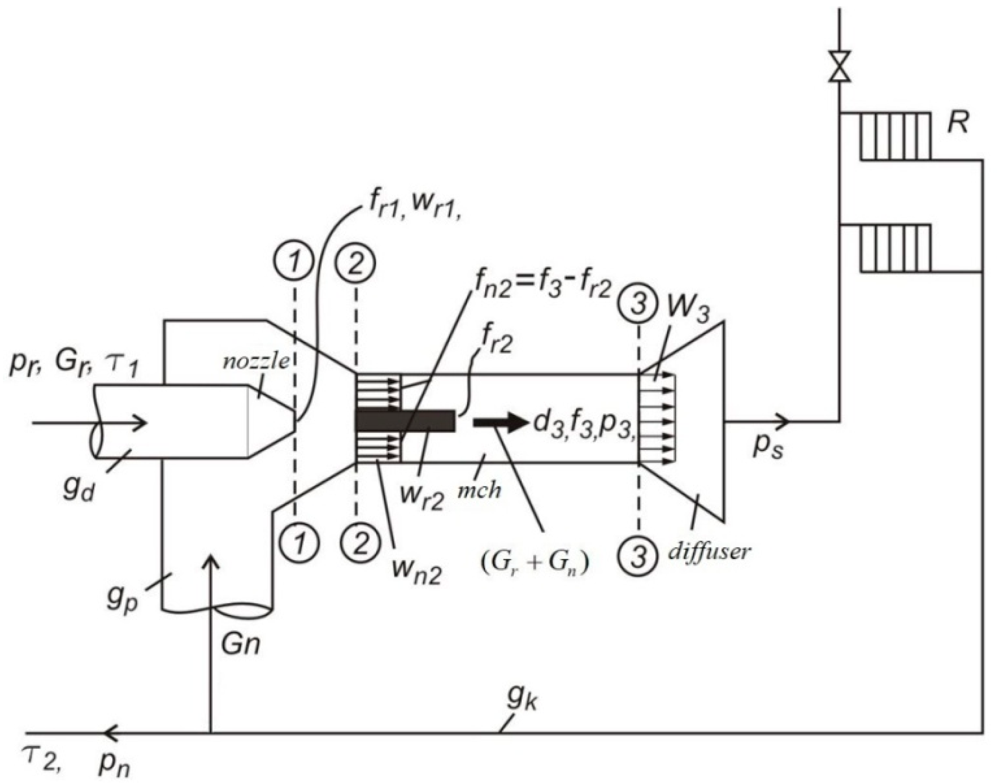
In some heating systems, the connection of thermal consumers with the thermal heating network is also completed with the use of the ejector. With this device, it is possible to mix the water of the supply network with a quantity of water of the return network to regulate the temperature of the water at the entrance in the heating device (radiator). The scheme of such a model is presented in
Figure 1. It generally consists of the nozzle, the mixing chamber, the diffuser, and the injection pipe. The supply water exits the nozzle in Section 1-1 and enters the mixing chamber at speed
Wr2. This stream of fluid creates a certain pressure in the (
gp) pipe and consequently a quantity of water is absorbed from the return network of the heating system. This amount of water is introduced into the mixing chamber in Section 2-2 at speed
Wn2. The created mixture leaves the mixing chamber in Section 3-3, passes through the diffuser, and then is sent to the heating system with R (radiators).
Regarding this model, the equation for the ejector characteristic is based on the impulse equation applied to non-compressible conditions. In this case, the impulse equation is applied for the mixing chamber. Two streams of water are introduced at the entrance of the mixing chamber, Section 2-2: main water passing through the ejector nozzle and water from return network that is mixed with the water in the supply network. This water mixture goes through the mixing chamber, Section 3-3. This mixture of water then flows through the diffuser and into the heating system. The impulse equation for the mixing chamber is:
Velocity of water in different sections is determined by the equations:
From the energy equation, the pressure of water at different sections is:
If expressions (2) and (3) are substituted in Equation (1), it follows:
From Equation (4), it follows:
The expression on the left side of Equation (5) can be expressed as follows:
From Equations (5) and (6), it follows:
From the continuity equation
, for the velocity of water through the nozzle
=
, the expression for the water flow through the ejector nozzle is:
If Equation (7) is divided by
, it can be written as:
Since water is considered an incompressible liquid with a specific volume
the equation of the ejector characteristic with the diffuser is equal to:
From Equation (10), it can be seen that for a value of the mixing coefficient u, the change in water pressure created by the ejector is in direct proportion to the change in pressure in the ejector nozzle. The ratio Δps/Δpr depends on the ratio of the cross sections of the components of the ejector, their velocity coefficients, as well as the mixing coefficient.
For non-diffuser ejector, its characteristic is given by the equation:
In order to apply the Math Cad program, to construct the ejector characteristic using Equations (10) and (11) the following substitutions were used:
Based on these substitutions, the characteristic of the ejector with a diffuser (Equation (10)) is now expressed as:
Similarly, the characteristic of the ejector without a diffuser (Equation (11)) is now given by equation:
The graphical presentation of the ejector characteristic in the Math Cad program, for the mixing chamber with diameter of
d3 = 15 mm and the nozzles with diameters of
d1 = 4, 6, 8, and 10 mm is done after defining the ratios below:
In
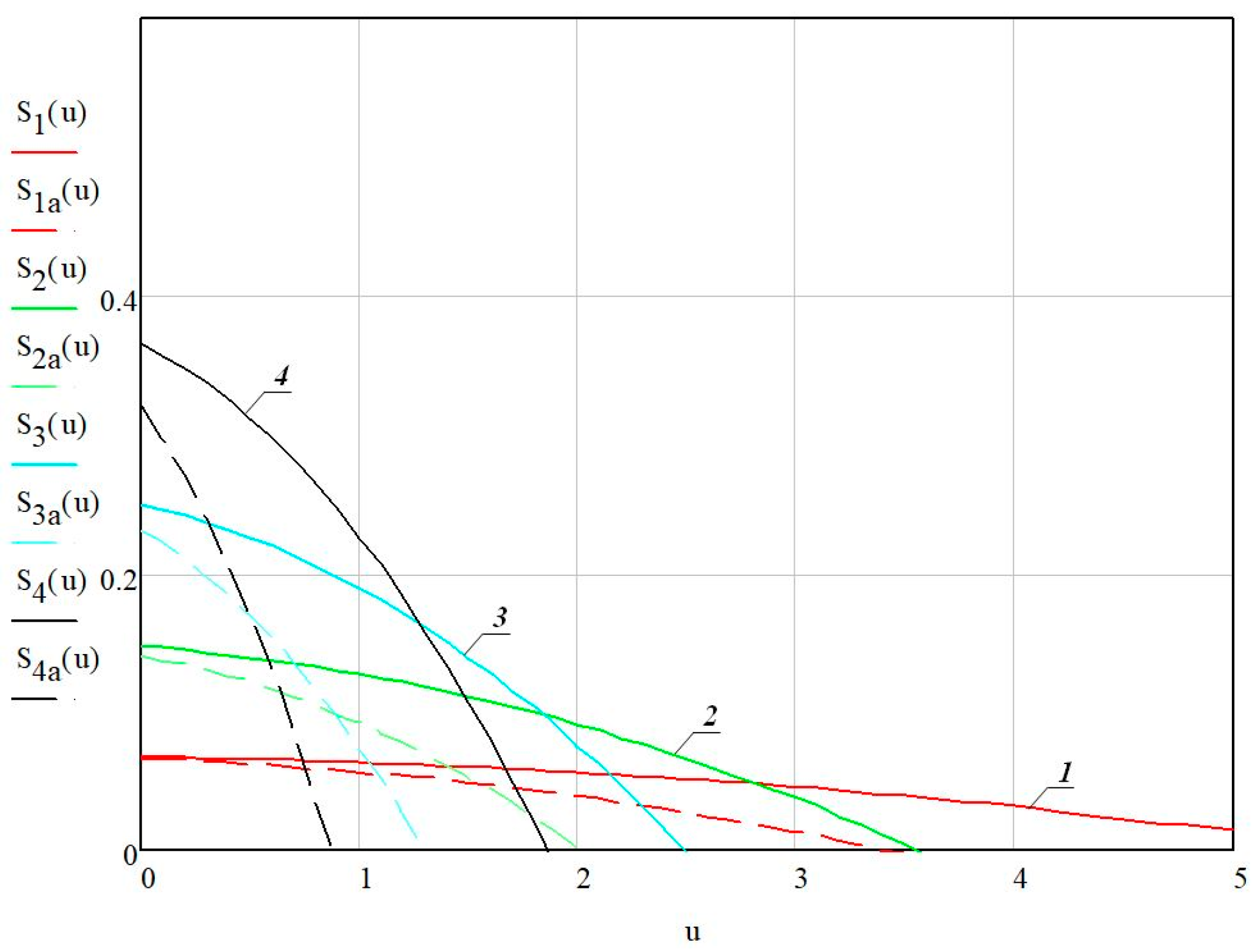
Figure 2 are given the characteristics of the diffuser ejector (shown with a continuous line), according to Equation (12) and the characteristics of the non-diffuser ejector (shown with dashed line), according to Equation (13).
The characteristic of the ejector with the mixing chamber diameter
d3 = 15 mm is constructed using nozzles with diameters
d1 = 4, 6, 8, and 10 mm. This analysis was also done for mixing chambers with diameters
d3 = 20, 30, and 40 mm using the same nozzle diameters. The diagrams are constructed and presented in
Figure 2,
Figure 3,
Figure 4 and
Figure 5.
From the diagram in
Figure 2, it can be seen that for the mixing chamber with diameter
d1 = 15 mm, by increasing the ratio of surfaces
f3/
fr1 = 2.25 to the value
f3/
fr1 = 14, the mixing coefficient increases from 1.25 to 4.2, which is realized with ejector nozzles with different diameters and there is a reduction in the ejector pressure difference from 0.57 to 0.12. The non-diffuser ejector with the same surface ratio
f3/
fr1 creates a mixing coefficient from 0.4 to 2.3, while is noticed a lower pressure difference from 0.41 to 0.12.
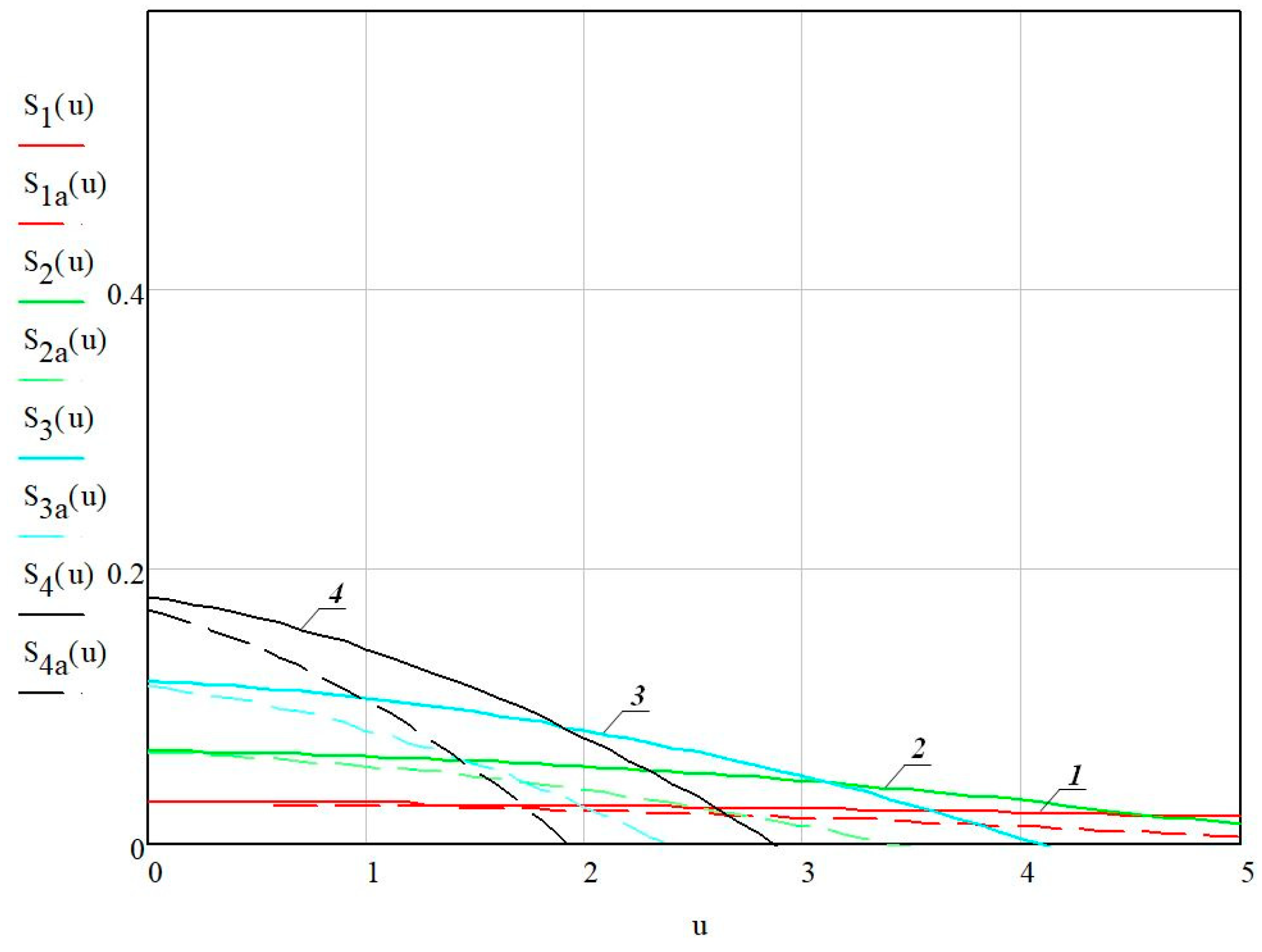
The characteristics of the ejector with mixing chamber diameter
d3 = 20 mm, with the same nozzle diameters, are shown in
Figure 3. For the mixing chamber with diameter
d3 = 20 mm, for the ratio
f3/
fr1= 4, the change in maximum pressure created by the diffuser ejector and non-ejector diffuser is 0.05 (15.15%).
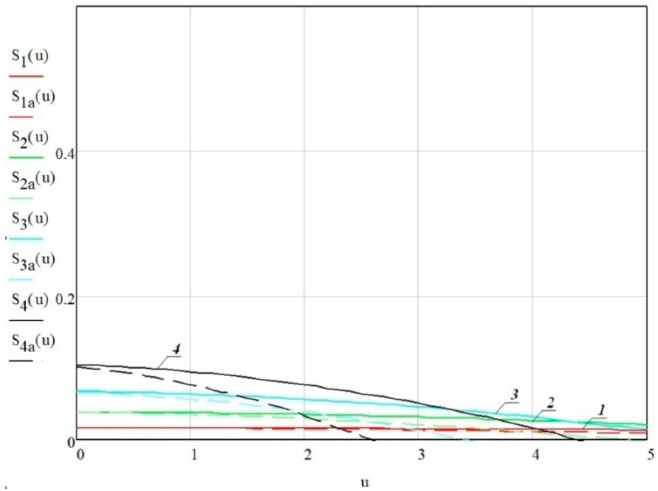
The characteristics of the ejector for the mixing chamber with diameter
d3 = 30 mm, with the same nozzles, are shown in
Figure 4.
As seen from
Figure 4 for the mixing chamber with diameter
d3 = 30 mm, the difference of the maximum pressure created by the diffuser ejector and the non-diffuser ejector is greatly reduced up to the value 0.01 (5.9%). This pressure difference is quite low for higher values of the ratio
f3/
fr1, and especially for the mixing coefficient
u < 1. In these conditions, the difference in the mixing coefficient
u created by the diffuser ejector decreases, for the ratio of surfaces
f3/
fr1 = 2.25 it is 2.8 while for the non-diffuser ejector it is 1.8.
The characteristics of the ejector for the mixing chamber with diameter
d3 = 40 mm, with the same nozzles, are shown in
Figure 5. From the diagrams in
Figure 2,
Figure 3,
Figure 4 and
Figure 5, it can be seen that by increasing the diameter of the mixing chamber, the pressure difference in the ejector decreases and, consequently, the mixing coefficient of water from the return network increases.
The ejector characteristic depends on the ratio of the cross-sectional areas f3/fr1 and does not depend on the absolute value of these surfaces. This means that two ejectors with different dimensions can have the same surface ratio f3/fr1, respectively, the same characteristic. As the f3/fr1 ratio increases, the mixing coefficient u increases but at the same time, the ejector effort decreases.
Ejectors characteristics for different diameters of the mixing chamber
d3 = 15, 20, 30, and 40 mm, respectively, for different ratios
f3/
fr1, are presented in
Table 1.
It is important to note that for a high value ratio of the f3/fr1, the value of the maximum pressure created by the diffuser ejector and the pressure created by the non-diffuser ejector is approximately equal. The change in pressure created by the ejector is more pronounced for lower values of the ratio f3/fr1, respectively, for higher values of the diameter of the ejector nozzle d1.
As the diameter of the mixing chamber d3 increases, for the same diameter of the ejector nozzle, the ejector mixing coefficient increases and at the same time the ejector pressure decreases.
For a case study of the ejector connected to a closed heating system with water supply , with pressure losses in the closed heating system =13,800 N/m2, and mixing coefficient u = 2.8, the calculations are given below:
The energy losses in this closed heating system are [
1,
2]:
The required diameter of the mixing chamber is [
3]:
The surface of the mixing chamber is f3 = 0.0007065 m2.
The diameter of the ejector nozzle is determined by the expression [
4]:
Appropriated as d1 = 8 mm.
The surface of the exit section of the nozzle is fr1 = 0.00005024 m2. The ratio f3/fr1 is 14.0625.
From Equation (8), for
=
(1 +
u) and
Vs = Gsvs, follows:
From the Equations (10) and (14), follows the expression for determining the water pressure at the exit of the ejector in function of the water flow:
For this case of the study, the ratio
f(
u) =
is read from the diagram in
Figure 4. For the ratio of surfaces
f3/
fr1 = 14.06, respectively,
fr1/
f3 =
fp3 = 0.0711, the characteristic of ejector is presented with curve number 3 and the same is given in
Table 1.
For
u = 1, see
Table 2, from Equation (10), the following can be written:
The ejector exit pressures are similarly defined for the other mixing coefficients
u, and calculated values are also presented in
Table 2.
Based on the data in
Table 2, the diagram in
Figure 6 is constructed, where the ejector characteristic and the network characteristic are shown (losses in the closed network of the heating system). At the intersection of these two characteristics the working point of the designed ejector is obtained, point A: flow
VA = 0.015808 m
3/s and pressure change (Δ
ps)
A = 199,272 N/m
2.
From the diagram it can be seen that for the same pressure drop in the ejector nozzle, with the increase of heating system network losses, Ss1 > Ss, the water flow and the mixing coefficient of the ejector u in the heating system Vs decrease while the pressure drop Δps increases. These findings are seen from the diagram when the operation point changes from point A to point B.
The operating point of the system also changes with the increase or decrease in the ejector characteristic. The diagram shows the case of decreasing the ejector characteristic for Δps1 < Δps. In this case, the operating point for network losses Ss is point A1 while it is point B1 for network losses Ss1 > Ss. In this case, the water flow in the system is decreased and so is the mixing coefficient u.
All symbols used in Equations above in the text are provided in
Table 3.
3. Results
From the analyses that were done related to ejector characteristic, it can be concluded that the pressure differences created by the ejector are in direct proportion with pressure drop in the nozzle.
The characteristic of the ejector depends on the ratio of the surfaces of the sections of the mixing chamber and the nozzle of the ejector f3/fr1. Therefore, the characteristic of the ejector does not depend on the absolute values of the surfaces of these sections. From the analysis of the equation of the ejector characteristic, it results that by increasing the ratio of surfaces f3/fr1, the coefficient of mixture u increases, and at the same time the pressure difference created by the ejector decreases.
For the ejector with a mixing chamber with a diameter of d1 = 15 mm, it is found that by increasing the ratio of surfaces f3/fr1 = 2.25 to 14, the mixing coefficient increases from 1.25 to 4.2, while the ejector pressure difference decreases from 0.57 to 0.12. The same ejector with the same surface ratio f3/fr1, but without a diffuser, creates a mixing coefficient about 2–3 times lower than the ejector with a diffuser.
It is important to note that for a high value of the ratio f3/fr1, the value of the maximum pressure created by the diffuser ejector and the pressure created by the non-diffuser ejector is approximately equal. The change in created pressure is more accentuated for lower values of the ratio f3/fr1, respectively, for higher values of the nozzle diameter d1.
Therefore, for the value of the surface ratio f3/fr1 = 2.25, which for the mixing chamber diameter of d3 = 15 mm corresponds to the nozzle with a diameter of d1 = 10 mm, the ratio change at the pressure created with the ejector with and without a diffuser is Δ(Δps/Δpr) = (Δps/Δpr)with diffuser − (Δps/Δpr)without diffuser = 0.57 − 0.41 = 0.16.
As the diameter of the mixing chamber d3 increases, for the same diameter of the ejector nozzle, the ejector mixing coefficient u increases, and at the same time the ejector pressure decreases.
The main findings from the research conducted are given in
Table 1, from which it can be concluded that the diffuser and non-diffuser ejector with mixing chambers
d3 = 15 to 40 mm, and nozzles with diameters of 4, 6, 8, and 10 mm, create certain pressure change at the exit of the ejector. For the same nozzle, the pressure increase is higher for the ejector with the smaller mixing chamber diameter, which in this case of the study is
d3 = 15 mm, while this pressure increase is lower when the diameter of the nozzle is lowered or when the diameter of the mixing chamber increases. Ejectors with mixing chamber diameter
d3 = 15 mm and nozzle diameter
d1 = 10 mm, create a pressure difference of 39% higher than the non-diffuser ejector, respectively, a pressure difference of Δ(Δ
ps/Δ
pr) = 0.16. Diffuser and non-diffuser ejectors with a mixing chamber with a diameter of
d3 = 30 mm, with the same ratio of cross-sectional surfaces
f3/
fr1 = 9, achieved with a nozzle diameter of
d1 = 10 mm, create a pressure difference of only Δ(Δ
ps/Δ
pr) = 0.01. When this nozzle is put in the ejector with the mixing chamber diameter
d3 = 40 mm, both types of ejectors realize the same pressure change, i.e., Δ(Δ
ps/Δ
pr) = 0. In this case, the diffuser ejector, compared to the non-diffuser ejector, with the same mixing chamber only increases the mixing coefficient
u.
From this case study, it can be noted that the diffuser ejector and non-diffuser ejector realize a significant increase in the mixing coefficient u. The highest increase of the mixing coefficient occurs with the diffuser ejector and it is higher for the mixing chamber with larger diameter d3, that in this case of the study is with diameter d3 = 40 mm. For illustration, the diffuser ejector with a mixing chamber diameter of d3 = 15 mm and the nozzle diameter of d1 = 10 mm, creates an increase in the mixing coefficient of Δu = 0.85 higher than the ejector without a diffuser. Meanwhile, the diffuser ejector with a mixing chamber diameter of d3 = 40 mm with the same nozzle, creates a mixture coefficient of 67.3% higher than the non-diffuser ejector.
From this research, it resulted that the diffuser impact is greater for high pressure ejectors which are characterized by a lower value of the ratio f3/fr1, while the diffuser has less impact for low pressure ejectors.


