1. Introduction
The smart grid enhances the overall operation of the power system by accepting the distributed intermittent generation such as micro-hydro, the photovoltaic, wind, etc. Among the challenges confronting the integration of these generators into the grid are (i) advanced mechanisms are required to maintain high energy efficiency, reliability, and power quality, and (ii) backup storage may be needed due to intermittency. The storage system is important to balance the variations in demand for energy. Several energy storage technologies are available, including flywheel, superconducting magnetics, batteries, pumped hydroelectric storage, and compressed air. Among these, pumped hydroelectric storage dominates for large capacity [
1]. Around 140 GW of fixed speed pumped storage power plants (PSPP) are under operation throughout the world [
2].
Initially, the PSPP was employed with the fixed speed in the early decades of the 20th century, where synchronous generators were started in pumping mode with the help of pony motors [
3]. The fixed speed PSPP employing synchronous machines has disadvantages in terms of system efficiency, which is impacted because of: (i) change in water head level throughout the year in dam, (ii) change in excess power availability in the grid for pumping mode, and (iii) change in power generation according to grid demand for generating mode. The advancement of hydroelectric PSPP laid the path for developing a Variable Speed Pumped Storage Power Plant (VSPSPP) wherein the speed of the turbine is adjusted by the water head to yield maximum efficiency and a variable speed generator is used [
4]. In 1993, Japan-based Hitachi Mitsubishi Hydro Corporation started to commission the first large-rated VSPSPP of 400 MW with the help of a cycloconverter to meet slip power requirements (±8.3%) [
5,
6]. In this application, a Doubly Fed Asynchronous Machine (DFAM) is used. In the pumping mode, starting of the pump-turbine is carried out by an additional static frequency converter due to the limitation of cycloconverter operation (below 16.66 Hz). (The DFAM is sometimes called a Doubly-Fed Induction Generator, or DFIG, when the asynchronous (induction) machine is used as a generator).
The advancement in power semiconductor devices in the mid-2000’s caused keen interest towards the employment of 2-level back-to-back converter topologies to meet the slip power demand. In a DFAM, the V/f start-up strategy is adapted for smooth starting and is enabled through the machine side converter. Once the machine reaches the rated speed, flux-oriented vector control is enabled to control the speed and power factor with high dynamic characteristics [
7]. The excitation circuit based on a 2-level voltage source converter suffers from high harmonics switching stress and needs a filter circuit in RSC (419.5 MVA Frades II) [
8,
9]. To overcome these practical challenges, Europe-based companies started commissioning 3-level neutral point clamped voltage source converters for the rotor excitation circuit (280 MVA Linth Limmern) [
10].
In the V/f starting method, the voltage and frequency ramp from low-end to the rated value by regulating the flux constant and increasing the torque gradually. In addition to this, the speed of the machine can be accelerated as per the user’s requirement using V/f starting [
11]. V/f starting is devised to overcome the problems such as torque pulsations, high inrush current, and heating of the machine which is common in other starting methods. This method is extensively used in all large-rated DFAM based variable speed pumped storage plants. During start-up, the torque is produced through electromagnetic induction where the slip is the key factor [
12,
13]. Similarly, the current in short-circuited stator winding depends upon slip frequency and airgap flux, which is directly proportional to the rotor current. Therefore, energy consumption during start-up depends upon slip power and starting duration [
14,
15]. It is found that a significant quantity of energy is dissipated due to slip [
16]. The slip increases the magnitude of current feeding into the motor to achieve its desired output, which causes vulnerability to the machine windings. There are two significant consequences of the slip: (1) it increases the consumption of energy and (2) it results in overheating due in the coils. These can cause early failure and more losses in the electric motor [
17].
The focus of the paper is to minimize the power consumption of a DFAM during the start-up process. To conserve energy by reducing slip and magnetizing current, and effective start-up strategy is developed and implemented in DFAM. This method applies a low voltage DC supply to stator windings instead of short-circuiting, which regulates the reactive power and eliminates the slip losses. Hence, the rated torque is developed with zero slip, i.e., no slip-related losses are produced during the electromagnetic interaction between the windings. This zero-slip ramping is executed when the rotor starts to rotate at around 25% of synchronous speed and continues till the machine is synchronized with the grid. The developed energy-efficient start-up strategy is modeled and simulated in Matlab/Simulink software and experimentally validated with a 2.2 kW DFAM. Based on simulation results, economic analysis for using this technique on a 250 MW hydrogenating unit is carried out, and it is found that the proposed system can save more than 26% of electrical energy relative to a conventional V/f start-up strategy for this application. The technique is not limited to pump-storage hydro plants, but also other systems incorporating DFAM generators.
2. Conventional Start-Up Strategy of DFAM
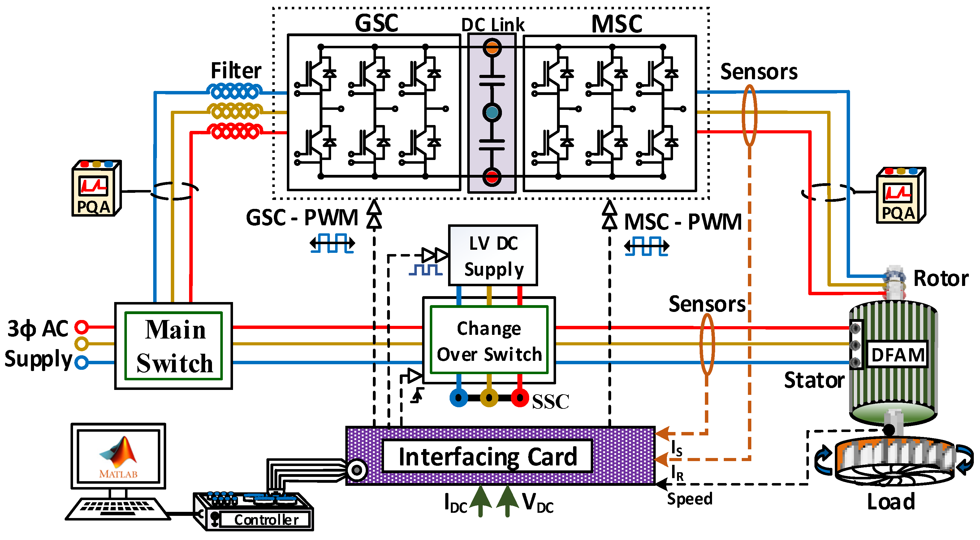
Figure 1 depicts the components and the connection of the DFAM system. The voltage source converter connected between rotor terminals of the machine and DC-link is known as Machine Side Converter (MSC). Similarly, the voltage source converter connected between the main supply and DC-link is known as Grid Side Converter (GSC) [
18,
19]. The DC-link acts as a storage element and decouples GSC and MSC in a back-to-back power converter set.
The DC-link supplies the required reactive power to the machine through rotor terminals. The DC-link capacity enhances the system’s overall system performance [
13]. Detailed control strategy with d-q modelling and control equations of GSC, MSC, and DC-link is presented in [
20,
21]. Compared with the traditional voltage-ramp starting method, the V/f starting method has various advantages such as simple control, faster response in starting time, low starting current, etc. During starting, GSC and MSC regulate DC-link voltage and provide a V/f ramp to supply rotor circuit current, respectively. Once the starting of DFAM is accomplished, a vector control strategy is adopted in MSC for controlling the speed and machine reactive power. The V/f starting method includes three main factors, the slope of the ramp, V/f ratio, and an initial “boost” voltage. The slope of the ramp determines starting time while considering rotor current and energy consumption, the starting period selection is essential [
11]. Similarly, the V/f ratio determines the starting flux of the machine. A Simulink model of V/f starting is briefly discussed in [
13]. The boost voltage is provided for developing the initial torque that overcomes the static torque and shortens start-up time. The value of the boost voltage is based on the rating of machine and rotor parameters, usually 20 to 50 percent of the rated voltage. In the course of starting, the electromagnetic torque (
) is derived as,
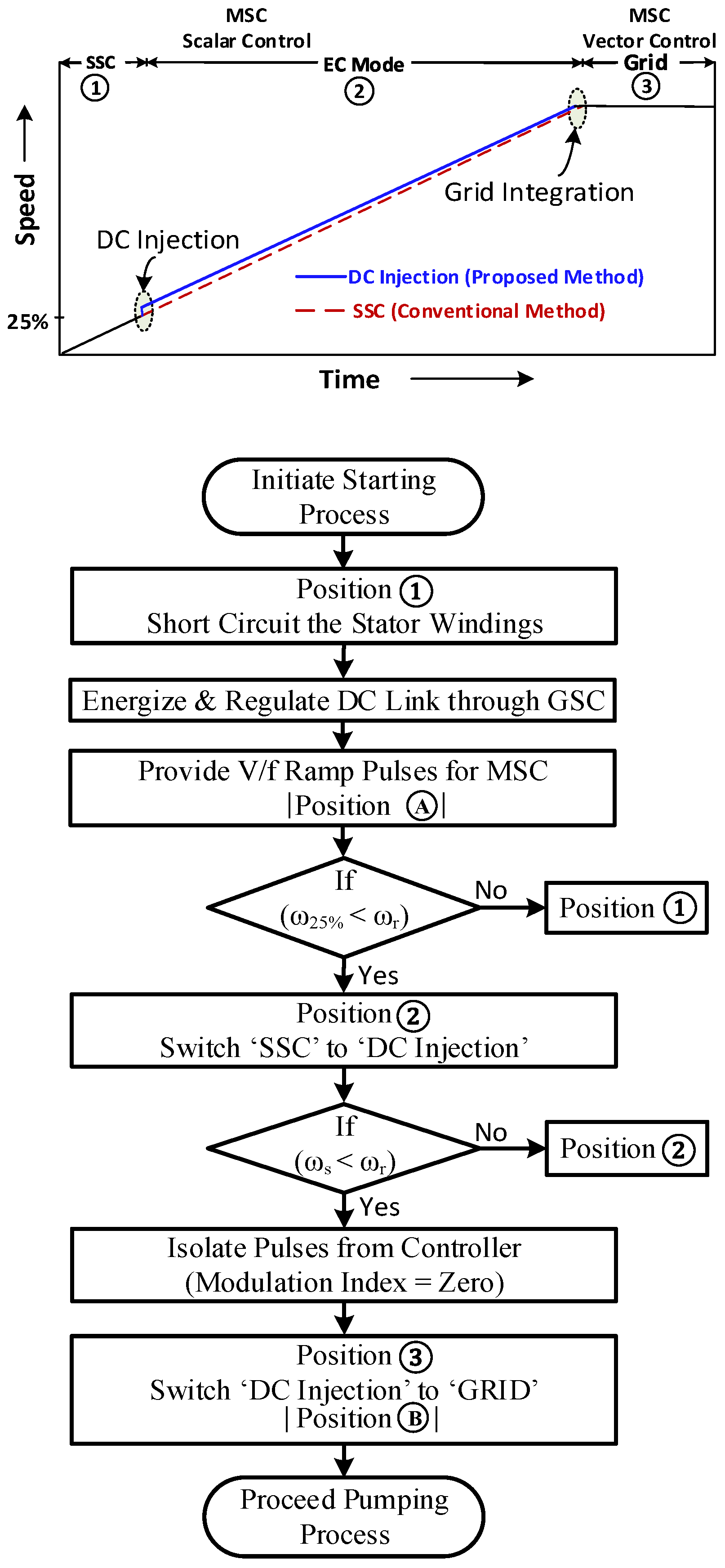
The stator windings are switched between the short circuit terminal and grid terminal using the transfer changeover switch in a conventional start-up strategy. The changeover switch unit consists of two circuit breakers (Main and SSC) and the operation of circuit breakers is based on the signal received from the controller. A high signal closes the switch and a low signal opens the switch, and also it is ensured that only one switch may be operated at a time. The switching logic is shown in
Figure 2a. The steps involved in the conventional start-up strategy of DFAM are given below.
- -
Step 1 (Initiate the start-up process): Stator short circuit (SSC) circuit breaker is closed, and the V/f ramp pulses (Scalar) are provided to the machine side rotor converter until the machine reaches the synchronous speed.
- -
Step 2: Once the machine reaches the rated speed, the V/f ramp pulses are disabled, and the SSC circuit breaker is opened.
- -
Step 3 (Synchronization): Pulses are re-enabled for adjusting machine parameters such as voltage amplitude, frequency, and phase angle of stator terminals.
- -
Step 4: Once the machine parameters are lined up with grid parameters, the main switch is closed, and the vector control strategy is adopted.
3. Energy Efficient Start-Up Strategy
During starting, the total current drawn by the machine depends on the reactive component current (magnetization), the torque component current (acceleration), and the stator equivalent current (slip frequency) [
22]. In the conventional starting method, all these currents are supplied from rotor converters that reduce the system’s overall efficiency. The energy conservation (EC) start-up strategy presented in this paper is designed to reduce no-load losses and slip losses during starting by injecting a low voltage DC signal in the stator windings. Applied properly, this low voltage DC injection provides the required reactive power and eliminates the slip losses.
The DFAM system with the proposed energy-efficient DC injection start-up strategy is shown in
Figure 1 and
Figure 2b. Similar to the conventional start-up, the energy-efficient DC injection start-up strategy consists of two control sections, grid side converter (GSC) control and machine side converter (MSC) control. The grid side controller regulates DC-link voltage and grid side reactive power [
23]. Likewise, the machine side controller increases voltage and frequency with an aspect ratio (V/f ratio) up to the machine’s rated value. Control signals from the controller are provided to the changeover switch for switching the stator winding connection from the short circuit connection, DC supply, and grid supply, as well as switching pulses to GSC and MSC. The changeover switching unit consists of three circuit breakers (Main, SSC, and DC injection), and the operation of circuit breakers is based on the signal received from the controller. A high signal closes and a low signal opens the breakers and ensures that only one switch can be operated at a time. The switching logic is shown in
Figure 2b. The EC start-up strategy, switching sequence, selection of transition point, and selection of DC voltage are the subjects discussed in the subsequent sessions.
3.1. Operational Sequence of the Proposed Strategy
The implementation of an energy-efficient DC injection start-up strategy in the DFAM system is carried out through a systematic procedure, shown in
Figure 3. The DC-link of the back-to-back voltage source converter is energized using a grid side converter before initiating the start-up. Once the DC-link voltage is regulated, the V/f ramp pulses are provided to the rotor converter for initiating smooth start-up “Position A—open-loop scalar control”. This operation is similar to the conventional starting approach of a DFAM. As soon as the speed of the rotor reaches 25 percent of its rate (where the rotor swing is curtailed), a low voltage DC supply is injected by switching the stator winding connection from a short circuit to a DC injection. During this period, the rotor speed matches with synchronous speed due to the elimination of slip losses. Finally, the stator windings are isolated from DC voltage and synchronized with the grid once the speed of the rotor reaches above its synchronous speed.
During this transition period, the pulses to the rotor converters are controlled to match the machine parameters such as voltage amplitude, frequency, and phase angle of stator terminals with grid parameters for synchronization. Once the machine is synchronized with the grid, the vector control strategy is adopted in MSC “Position B—closed-loop vector control”. The operational sequence of the proposed energy-efficient dc injection start-up strategy is shown in
Figure 2b. Stator winding connections are switched using circuit breakers during the starting process, whereas the switching of scalar control mode and vector control mode is carried out through a soft-switching mode. The steps involved in the energy-efficient dc injection start-up strategy of the DFAM are given below.
- -
Step 1 (Initiate the start-up process): Stator short circuit (SSC) circuit breaker is closed, and the V/f ramp pulses (Scalar) are provided to the machine side rotor converter until the machine reaches 25 percent of synchronous speed.
- -
Step 2 (Energy Conservation): At 25 percent of synchronous speed, the SSC circuit breaker is opened, and the DC injection circuit breaker is closed.
- -
Step 3: Once the machine reaches the synchronous speed, the V/f ramp pulses are disabled, and the DC injection circuit breaker is opened.
- -
Step 4 (Synchronization): Pulses are re-enabled for adjusting machine parameters such as voltage amplitude, frequency, and phase angle of stator terminals.
- -
Step 5: Once the machine parameters are lined up with grid parameters, the main switch is closed, and the vector control strategy is adopted.
3.2. Selection of Transition Point (SSC to DC Injection)
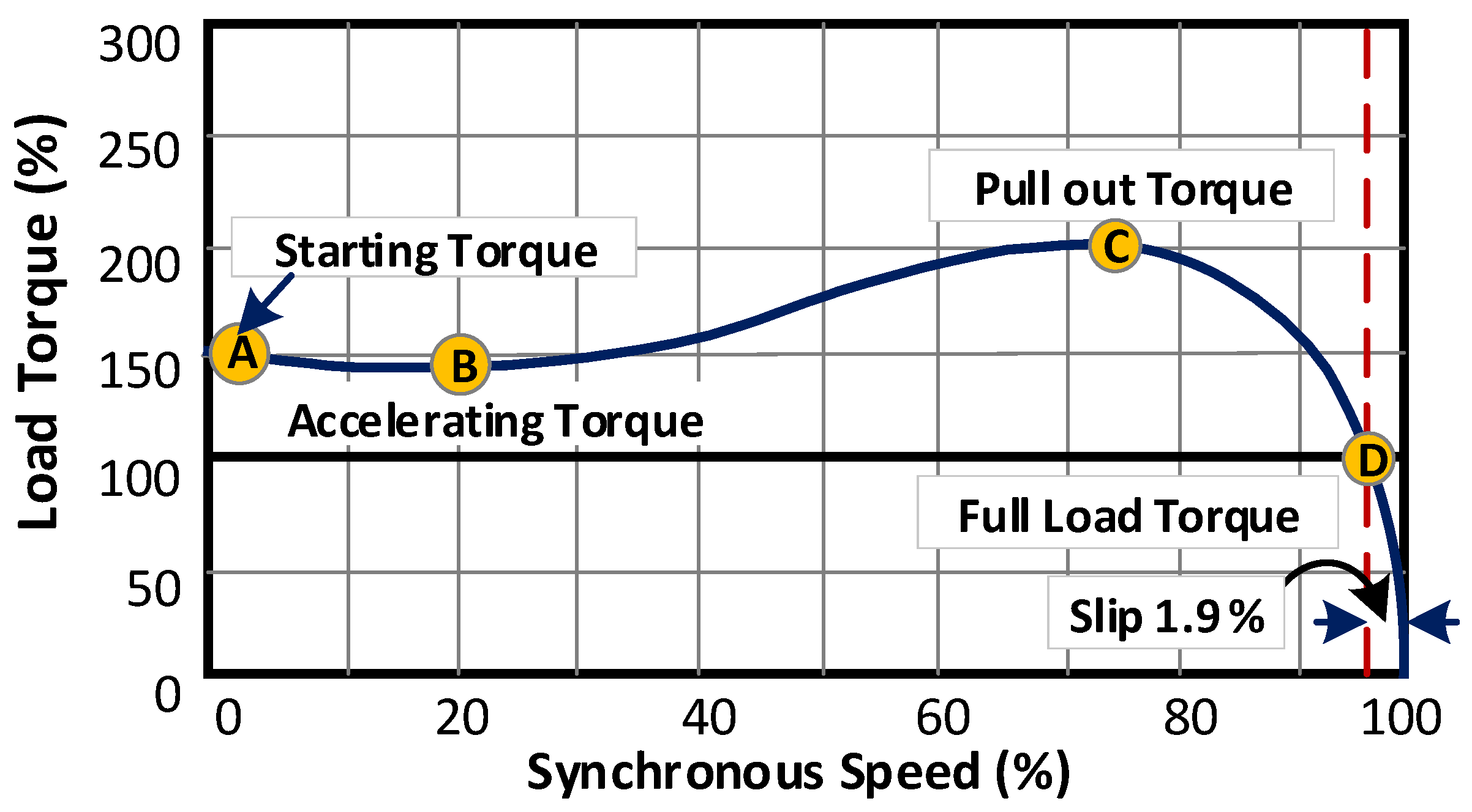
Energy is conserved through switching the stator winding of the doubly-fed asynchronous machine from SSC to DC injection. During this transition, it is mandatory to ensure the rotor and stator flux magnitude swing should be within an acceptable limit so it will not produce undesirable electromagnetic torque and power disturbances to the machine and grid [
23]. As per the speed-torque characteristics of the induction motor, as shown in
Figure 4 [NEMA Std.], it is shown that the pull-up acceleration takes place after 20 percent of synchronous speed. Also, as stated by Allen-Bradley, the changes in machine acceleration take place between 25 percent and 40 percent [
24,
25]. Through Matlab simulation, the speed-torque characteristics of a DFAM are analyzed with a conventional V/f start-up strategy. The result shows that the machine produces high electromagnetic torque at the initial stage of starting and stabilizes after the machine’s acceleration. Further, it is noticed that the current and flux component of the machine is also stabilized after the acceleration. Therefore, it is decided to inject the DC voltage supply into the stator circuit after the stabilization of electromagnetic torque. This could reduce pulsations in speed and torque. Also, it is noted that the stabilizing point varies with respect to the start-up duration, power rating, and moment of inertia of the machine.
3.3. Selection of DC Voltage
The magnitude of DC voltage depends on the transient characteristics of the DFAM. Usually, to avoid oscillations, the DC supply is injected into high voltage winding [
26]. Also, starting or switching current should not exceed the converter rating, but the torque should be sufficient to drive. The DC voltage is selected in consideration of performance-related parameters, i.e., the stator and rotor currents of the DFAM should not exceed the nameplate ratings. The dynamic limit of stator and rotor current is clarified through (2) and (3) respectively.
where,
. The DC voltage is applied at no-load conditions; therefore, the machine does not produce as many transients as compared to loaded conditions. During conventional starting, the magnetic flux of the machine is maintained by d-axis rotor current only. With a DFAM, the machine is associated with both rotor and stator d-axis currents as per (4). Further, any one of the d-axis currents (either d-axis stator current or d-axis rotor current) is enough to provide the required magnetic flux of the machine [
27,
28].
The technique provided in this paper creates the required magnetic flux by d-axis stator current from the DC supply. The magnitude of the DC voltage is estimated based on the requirement of reactive component current during starting (no-load) and also no-load torque is considered. The estimation of reactive component current (
) is calculated from the rotor current of the machine by Clarke and Park transformations. The DC voltage connected to the stator circuit is estimated by
,
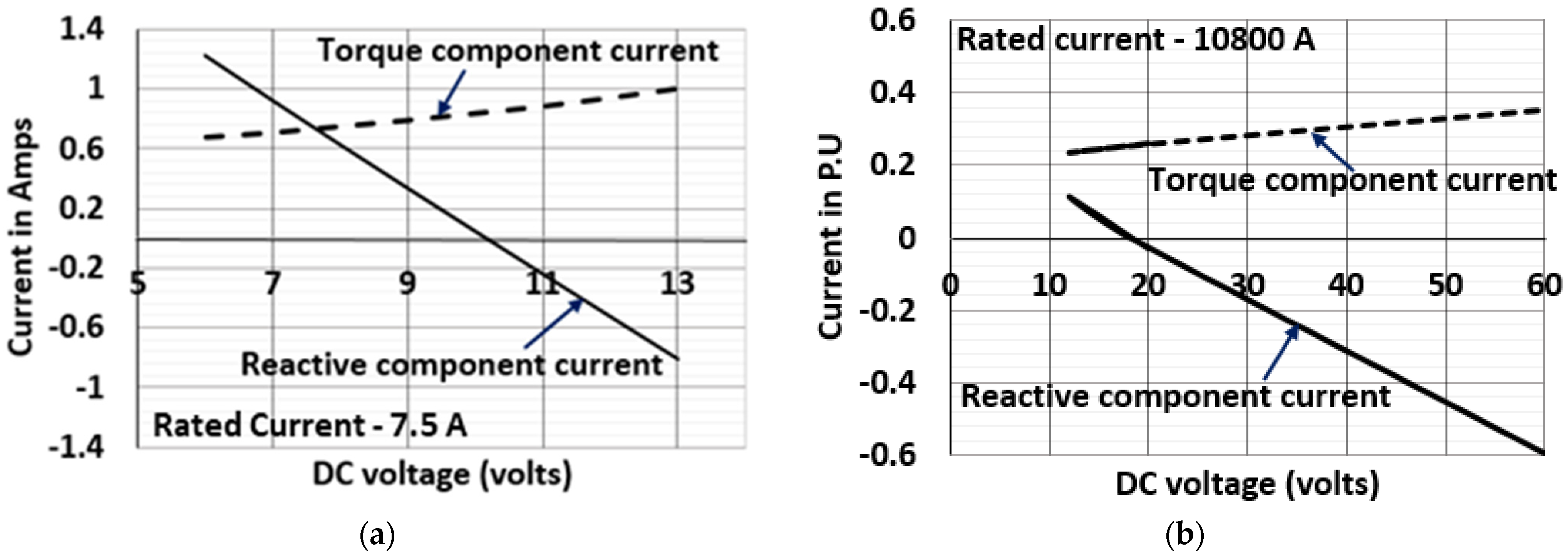
. Alternatively, the DC voltage can be estimated based on stabilization characteristics of the 2.2 kW DFAM test machine and 250 MW DFAM, as shown in
Figure 5a,b, respectively. The stabilization characteristics are plotted between DC injection voltage and reactive current components. The selected DC voltage value (in case 250 MW DFAM, 2500/25 V, 4000 A) is injected to DFAM through rotor slip rings from a low voltage DC source to reduce the slip losses and provide the required reactive power for the start-up.
3.4. Energy Efficient DC Injection Start-Up Strategy
The realization of the proposed energy efficient start-up strategy is carried out using the experimental arrangement depicted in
Figure 6. The hardware setup consists of a 2.2 kW DFAM coupled with a dynamometer loading arrangement. A two-level IGBT based back-to-back voltage source converter (GSC and MSC) with a DC-link filter is connected between the grid and rotor terminals of the machine. The GSC controls the grid’s reactive power and maintains the DC-link voltage constant (325 V). The MSC also provides variable voltage variable frequency supply to the rotor windings and controls the machine’s reactive power. A low voltage DC supply is connected to the stator winding during an energy-efficient start-up.
The following alterations to the machine were made to execute the intended research. The manual spring balance dial and the frames are removed, a load-cell arrangement is built for torque measurement. Similarly for speed measurement, the tacho-generator is replaced with a quadrature encoder pulse (QEP) sensor. A quadrature encoder pulse (QEP—Avago HEDS 5645-113) sensor is connected to the shaft for providing the pulses to the controller (512 pulses/revolution) with respect to speed and position. To control the voltage source converter and changeover switch, a real-time controller (TMS320F240 DSP) interfaced with Matlab/Simulink software is used. The Optocoupler circuit is used to isolate and intensify all the signals from the controller. To sense the voltage and current signals, Hall Effect voltage and current sensors (LV-25 P & LTS 25 NP) with an active filtering circuit are employed in the circuit. Also, the changeover switching unit consists of three 3-pole contactors with an auxiliary switch (L&T MNX 32 and MNX A1) for switching the stator windings between SSC, DC injection, and main grid supply. An additional breaker is also employed to alternately isolate or connect the rotor windings from MSC. All the breakers are controlled through optoisolated relay units (SRD-5V-SL-C, 10A). The electrical input quantities of rotor and stator are measured and recorded through three-phase power quality analyzers (PQA—Fluke 435) and dSPACE control desk 3.7.3 automation. The recorded results are analyzed using Fluke view and Power log software. A snapshot of the experimental arrangement is depicted in
Figure 6. The rating of the test machine is tabularized in
Table A1 (
Appendix A).
5. Smooth Starting of 250 MW Pump Turbine at 1000 MW Tehri PSP—A Case Study
This section analyzes the developed energy-efficient start-up strategy on a 250 MW DFAM based pump-turbine from an economic perspective. In India at the Tehri dam, a DFAM based variable speed pumped storage power plant is under construction, which we’ll use for reference. In India at Tehri dam, DFAM based variable speed pumped storage power plant has a capacity of 1000 MW (250 MW × 4 units). The Tehri PSP is operated to recycle the discharged water from the lower reservoir, called the “Koteshwar dam”. It consists of four units of DFAM-based reversible pump turbines with a capacity of 250 MW each. This plant is being constructed underground on the left bank of the Bhagirathi River. The main feature of this PSP is head variation, which is about 90 m bands. The water system has 3 locations where valves/gates are located. At the intake, a sluice gate is provided followed by a butterfly valve at penstock. Right at the entry of the spiral casing, the main inlet valve (MIV) is provided. All control and protection related sequences make use of MIV. Other valves are used to facilitate maintenance activities of the water conductor system. Speed variation of DFAM is ±10 percent of the rated speed (230.77 rpm) and the rating of the power converter is about 10% of the machine rating of 250 MW (
Figure 9).
Figure 10 shows the operational sequence of PSPP from generation to pumping. The machine speed is reduced to a standstill and starts back in the reverse direction to transition to the pumping mode from the generation mode. During starting, the energy-efficient start-up sequence is adopted. Implementation of the proposed method in the pumped storage hydropower plant involves the following steps:
- -
Step 1: The stator circuit of the machine is shorted (the main circuit breaker is opened, and SSC is closed), and the rotor is energized with V/f control by machine side converters (MSC). During smooth starting, starting current should not exceed the acceptable limit and maintain a constant torque. The flowchart in
Figure 10 indicates the starting sequences.
- -
The rotor is energized using variable voltage variable frequency ramp supply with short-circuited stator winding for initiating start-up.
- -
Step 2: Stator windings terminals are switched from SSC to the DC supply once the machine attains 25 percent of its rated speed, and is continued up to rated speed (approximately at 70 s from starting). Once DC supply is injected, the reactive power producing current reduces to a minimum value (0.009) p.u. whereas, the torque producing current remains the same. The slip of the machine becomes zero during DC injection which eliminates the slip losses. These factors reduce the overall energy consumption of machines during start-up.
- -
Step 3: Stator windings are switched over to the grid supply once the rotor reaches its rated speed and the gate valve is opened.
To demonstrate the energy efficient starting, a 250 MW DFAM is modelled and simulated in MATLAB/Simulink software and the structure is executed based on the starting sequence given in
Figure 10. The switching frequency of the rotor side converter is selected as 300 Hz; the DC-link voltage of the 3-level back-to-back voltage source converter is maintained at 5000 V by grid side converter with the switching frequencies of 500 Hz. The sampling time is selected as 500 μs and parameters of 250 MW DFAM are given in
Table A1.
The duration for smooth starting is selected as 250 s for starting, and boost voltage and frequency ratio are selected as 430 volts and 7 Hz respectively. The fixed DC voltage is selected as 16.8 volts by considering the reactive current component and dc source voltage characteristics (see
Figure 5b). The rotor speed at which the changeover switch is operated from stator short-circuited to DC supply is 27% of the synchronous speed. The converter voltage rating is selected by the minimum voltage required during starting of the machine. In the proposed method, the machine rotates at synchronous speed after injecting DC supply to the stator circuit. Thus, the slip losses are zero when the machine operates at synchronous speed. Meanwhile, the speed of the machine is increased due to the elimination of slip with a slight oscillation. Since the DFAM is started with no-load, this oscillation should not affect the system’s performance. Likewise, during start-up with SSC, the rotor line voltage ramps from 990 to 3300 volts and consumes power up to 15.48 MVA (max), which includes 9.8 MW of active power and 11.95 MVAR of reactive power, whereas the proposed strategy consumes up to 11.38 MVA (max), shown in
Figure 11b. Once after stablization, the power consumption is reduced to 6.67 MVA and 2.08 MVA for the conventional SSC and the proposed DC injection stragey respectively. In the conventional method, the machine consumes about 0.2896 p.u (3128 A) of reactive component current for magnetization and 0.210 p.u (2268 A) of torque component current for acceleration. Whereas, both reactive and torque component current produces transients of about 0.4742 p.u (5121 A) and when the reactive component current approaches zero, the torque component rises to 0.2554 p.u (2748 A) during DC injection, as shown in
Figure 11c,d.
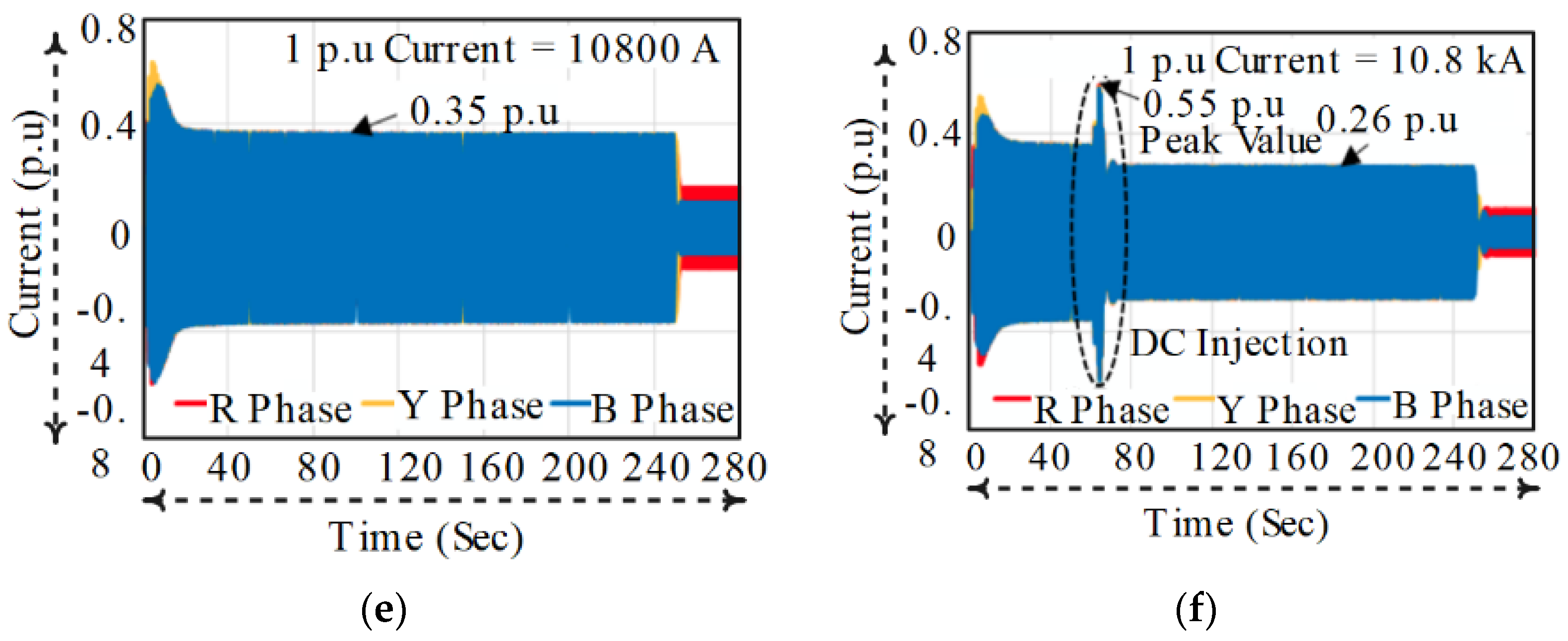
During the short circuit condition on the stator side, Phase A carries 0.308 p.u (3465 A), phase B carries −0.02 p.u (225 A) and phase C carries −0.284 p.u (−3195 A) currents, shown in
Figure 11e. Also, it is observed that the maximum transient current (phase A) produces at the stator circuit when DC is injected to stator winding is 0.55 p.u (6188 A), shown in
Figure 11f. The simulation results show that the rotor and stator current of the DFAM during the transition period (SSC to DC injection) is below the rated value (10,800 A) and it should not produce any harmful effect on the machine.
The energy consumption of DFAM with conventional stator short circuit start-up method and DC injection start-up method are presented in this section. Experimental results ae evidently shows that during conventional start-up, the machine consumes 0.01534 units (kW-h) of energy whereas the proposed start-up strategy consumes only 0.00977 units. The estimation of energy consumption is calculated through the Equations (5)–(7) and the results are tabulated in
Table 1. The experimental results evidently prove that there is less transients (0.781 p.u = 5.86 A) during transition period (SSC to DC injection) and also saves about 36.31% energy from conventional stator short circuit based start-up of pump turbine. Similarly, the proposed energy efficient smooth starting method for 250 MW DFAM saves about 35.35% energy from conventional stator short circuit-based start-up of pump turbine.
The benefit of this proposed method is estimated for a 250 MW pump-turbine at 1000 MW Tehri PSP. The energy consumption and conservation for each unit of the plant are calculated and presented in
Table 2, using the assumption of starting the DFAM with the proposed EC strategy twice per day and 360 days of operation in a year. If the pump-turbine is started twice a day, the financial benefits are approximated as Rs. 5 lakhs/year (at Rs. 3/kWh), or about
$6600 USD/year. The machine’ at stator short-circuited and the DC injection strategy was calculated using (5)–(7). If this calculation is extended for all four units, total financial benefits will be estimated as Rs. 20 lakhs/year about
$26,400 USD/year. The cost of the proposed energy efficient start-up system is much lower than this financial benefit and provides a payback period of less than one year.
where,
ES is total energy saved in kilowatt-hour,
ESSC is the total energy consumed during starting with stator short circuit method kilowatt-hour,
EDC is the total energy consumed during starting with the proposed starting scheme in kW-hr,
ST is total starting time in hours,
n is the number of samples, α is the starting time in hrs.,
βSSC is the power consumed on stator short circuit method in watts, and
βDC is the power consumed on the proposed scheme in kW. From this analysis, it is found that the energy savings during starting of the DFAM-based pump-turbine by adopting the new start-up method is 26.1%, leading to a significant economic benefit.


 ,
, 


