
Study on the Distribution Law of Coal Seam Gas and Hydrogen Sulfide Affected by Abandoned Oil Wells


1
College of Safety Science and Engineering, Liaoning Technical University, Huludao 125105, China
2
Key Laboratory of Mine Thermo-Motive Disaster and Prevention, Ministry of Education, Huludao 125105, China
*
Author to whom correspondence should be addressed.
Energies 2022, 15(9), 3373; https://doi.org/10.3390/en15093373
Submission received: 22 March 2022
/
Revised: 22 April 2022
/
Accepted: 29 April 2022
/
Published: 5 May 2022
(This article belongs to the Topic Mining Safety and Sustainability)
Abstract
:This paper is devoted to solving the problem of how to comprehensively control coal seam gas and hydrogen sulfide in the mining face, distributed from the coal seam in abandoned oil wells in coal mining resource areas. The abandoned oil wells of Ma tan 30 and Ma tan 31 in the No. I0104105 working face of the Shuang Ma Coal Mine were taken as examples. Through parameter testing, gas composition analysis, field investigation at the source distribution, and the influence range of gas and hydrogen sulfide in coal seam in the affected range of the abandoned oil wells were studied. The results show that the coal-bearing strata in Shuang Ma coal field belong to the coal–oil coexistence strata, and the emission of H2S gas in the local area of the working face is mainly affected by closed and abandoned oil wells. Within the influence range of the abandoned oil wells, along the direction of the working face, the concentration of CH4 and H2S gas in the borehole increases as you move closer to the coal center, and the two sides of the oil well show a decreasing trend. In the affected area of the abandoned oil well, the distribution of the desorption gas content in coal seam along the center distance of the oil well presents a decreasing trend in power function, particularly the closer the working face is to the center of the oil well. The higher the concentration of CH4 and H2S, the lower the concentration when the working face moves further away from the oil well. The influence radius of CH4 and H2S gas on the coal seam in the affected area of Ma tan 31 abandoned oil well is over 300 m. The results provide a theoretical basis for further understanding the law of gas and hydrogen sulfide enrichment in the mining face and the design of treatment measures within the influence range of abandoned oil wells.
1. Introduction
As more and more producing oilfields in the world enter the mature stage, abandoned oil wells have become a problem that the world needs to deal with urgently. Oil drilling activities that have lasted for more than a century have left great hidden dangers. Millions of abandoned oil and gas wells scattered in many countries have become the most serious environmental challenge in the world [1]. Taking the United States, Canada, and China as examples, the United States does not have specific statistics on abandoned oil and gas wells, but, according to the EPA (Environmental Protection Agency, Washington, DC, USA), there are about 3 million in California, Arizona, New Mexico, and Texas alone. Abandoned oil and gas wells pose a serious threat to local water sources, soil, and wildlife. An unknown number of aging, unplugged, and abandoned oil and gas wells are rampantly releasing methane and other greenhouse gases across the continental United States, bringing toxins to the surface, polluting groundwater and the surrounding ecosystem. Furthermore, these oil and gas wells are spread all over North America [2]. EPA estimates that the annual emissions of methane leaking from abandoned oil wells in the United States are about 263,000 tons, equivalent to the carbon emissions of more than five coal-fired power plants. According to Columbia University in the United States, methane emissions from abandoned oil and gas wells in the United States are as high as 280,000 tons per year, equivalent to the carbon dioxide emissions of 2.1 million cars. More than half of Canada’s oil and gas wells have been out of service for more than a decade, Canada’s energy regulator said, with a more than 50 per cent increase in idle wells in the province between 2015 and 2021, with 6014 more expected to be idled in 2022. The surrounding environment of abandoned oil wells is full of hidden dangers, which increases the difficulty and cost of treatment of abandoned oil wells in various countries [3].
China’s abandoned oil wells are increasing year by year. According to incomplete statistics, the number of abandoned oil wells increased by 25,119 from 2005 to 2010, with an annual growth rate of 19.7%; by 2021, the total number of abandoned oil wells will reach 150,000. In northwest China, there are numerous mining areas with superimposed resources and a large amount of coal, oil, natural gas and other resources existing in the area [4].
Fossil fuel companies around the world emit a large amount of toxic and harmful gases into the atmosphere every year, destroying the natural and ecological climate environment on which human beings depend [5]. The production of sulfur dioxide, carbon monoxide, soot, radioactive dust, nitrogen oxides, carbon dioxide and other substances during the combustion of fossils will directly harm human health, cause human cancer and cause radiation damage to organisms. Fossil fuels contain sulfur, which will produce toxic sulfur dioxide when burned, causing acid rain and damaging the ecological balance. Burning fossil fuels also produces carbon particles, which pollute the air and cause respiratory diseases. Burning fossil fuels also releases carbon dioxide, which eventually creates a greenhouse gas effect that causes sea level rise and threatens human habitation. Global warming will induce certain diseases, threatening the safety of people, especially the elderly. Frequent extreme climates, such as droughts, floods, storms and heat waves, threaten the living environment of animals and plants, increase the mortality rate, disability rate and infectious disease rate, and lead to climate change in some areas, thereby affecting the production and living environment of people in the area. At the same time, it also increases social psychological pressure [6].
Due to the early development of oil, natural gas and other resources, there are many abandoned oil wells in coal mining areas, and there is a large amount of water, gas, oil, etc. in the oil wells, which brings major safety hazards to the mining of mines. Among them, gas and hydrogen sulfide are the main toxic and harmful gases in the process of oil and gas well field exploitation, especially hydrogen sulfide, which, as a highly toxic gas, is seriously harmful [7]. The Shen fu coalfield in the Ordos basin is the largest coalfield proven in China and the largest integrated gas field proven on land. The mining area is rich in coal, oil, natural gas, and rock salt resources [8]. The coexistence of coal resources and oil exists in the Ma jia tan mining area in the western margin of the Ordos Basin [9]. There are also symbiosis phenomena of coal resources and oil in coal mining areas such as Huangling in Shanxi and Yao jie in Gansu [10]. Due to the early development of oil and natural gas resources, there are many abandoned oil and gas wells in overlapping resource areas. These abandoned oil and gas wells have brought great difficulties to the mining design of coal mines. It not only causes a waste of resources but also has significant safety hazards for the mining of coal seams adjacent to oil and gas wells [11].
Once the excavation roadway exposes the oil and gas wells, there will be significant safety hazards such as water, gas, and oil pouring into the working face, which seriously restricts coal mines’ safe and efficient production [12]. The Shuangma Wellfield overlaps with the “Hu jianshan oil and gas exploration in Shaanxi, Ningxia, and Mongolia Ordos Basins” block of Petro-China. Shuangma coal mine is located in the overlapping area of coal and oil exploitation. There are 170 abandoned oil wells in the minefield [13].
In the past ten years, ten abandoned oil wells have affected the mining face. Many harmful gases such as gas and hydrogen sulfide have gradually escaped into the coal seams in the oil wells [14,15]. The concentration of gas and hydrogen sulfide in the affected area of abandoned oil wells suddenly increases, bringing great hidden dangers to the safe mining of the mining face of the mine [16,17]. The sudden emission of hydrogen sulfide in the affected area of abandoned oil wells causes not only personal injury but also has explosive and corrosive coal mine equipment and monitoring and testing facilities, and other hazards [18]. Hydrogen sulfide is a standard toxic and harmful gas in coal mines [19,20]. In response to the severe harm of hydrogen sulfide in coal mines, domestic and foreign research on prevention and control technologies for coal mine hydrogen sulfide ventilation and dilution, coal extraction, spraying of alkaline solution, and coal pre-injection of alkaline absorption liquid have been carried out [21,22]. At the same time, excellent results have been achieved. However, only a few studies on the law of hydrogen sulfide enrichment in coal mines, especially the occurrence of toxic and harmful gases such as gas and hydrogen sulfide within the influence range of abandoned oil wells, have been carried out. Only some scholars have carried out preliminary research on oil well plugging and coal seam hydrogen sulfide treatment [23,24,25]. In this regard, the author researches the source and distribution of gas and hydrogen sulfide under the influence of oil wells in Shuangma coal mine and the scope of power to provide a theoretical basis for the design of gas and hydrogen sulfide treatment measures within the influence scope of abandoned oil wells. Moreover, the research theory of this paper provides technical support for the coordinated exploitation of coal and oil, reduces the potential safety hazards in the process of coal mining near oil and gas wells, and ensures the safe, environmentally friendly and efficient development and production of coal, oil, natural gas and other mineral resources.
2. Analysis of Gas Sources
2.1. Gas Source Statistics during Face Excavation
According to on-site statistics, since the Shuangma coal mine was produced, there have been no abandoned oil wells in or near the I0104102 working face and I0104103 working face that have been stopped. There has never been H2S in the working face during the tunneling and mining period. The first occurrence of H2S in the mining face is the return air lane of the I0104104 working face, the return air lane of the I0104105 working face, the transportation lane I0104105 working face, and the return air lane of the I0104106 working face. According to the mining layout of the mine, this area is mainly the abandoned oil well of Ma tan 31, with a strike distance of 460 m. The relationship between the driving face and the H2S gushing position is shown in Figure 1.
According to the H2S gushing position relationship shown in Figure 1, the H2S gushing situation during the excavation of the working face is counted, as shown in Table 1. According to the statistical results shown in Table 1, H2S will gush out only when the areas near the abandoned oil wells of Ma tan 30 and Ma tan 31 are operated, and the closer the distance to the abandoned oil well, the greater the concentration of H2S gushing from the tunneling face [26].
2.2. Analysis of Gas Composition in Detection Boreholes
Taking the abandoned oil well of Ma tan 31 as an example, the center of the oil well is 80 m (vertical distance) from the return airway of the I0104105 working face, 203 m (vertical distance) from the transportation lane, and the distance to the open-cut is 376 m, passing through 4-1 coal seam, 4-2 coal seam and 4-3 coal seam from top to bottom. When section II of the return air lane of the I0104105 working face was excavated to a position of 1050 m away from the No.5 connecting lane, two detection boreholes were constructed on the working face (the K1 borehole and K2 borehole were, respectively, 85 and 60 m away from the center of the abandoned oil well of Ma tan 31), The drilling layout is shown in Figure 2. Gas samples were then collected in the holes for gas detection and analysis. At the same time, a detection borehole was constructed in the return airway of the I0104105 working face (the borehole is 41 m south of the abandoned oil well in Ma tan 31), and gas samples were collected in the borehole for detection and analysis to obtain the gas component. The measurement results are shown in Table 2.
According to the gas composition analysis results in Table 2, the volume fraction of H2S in borehole K1 is 38,033.52 × 10−6, and the volume fraction of H2S in borehole K2 is 25,599.14 × 10−6.
As shown in Table 3, according to the gas analysis results of the borehole 41 m to the south from the abandoned oil well of Ma tan 31, the main harmful gas components in the borehole are CH4, H2S, CO, and C2 alkanes (the H2S gas component has a volume fraction of 10,200 × 10−6), which is roughly the same as the main gas components (CH4, H2S, CO, C2H6 et al.) commonly found in oil wells.
Based on further analysis of the literature [27,28], it is concluded that the leading harmful gases in the mining activities affected by abandoned oil wells in the Shuangma coal mine are H2S and CH4, which further shows that H2S at the working face mainly comes from abandoned oil wells and is enriched in a specific range of the affected area of abandoned oil wells.
3. Analysis of the Positional Relationship between Oil Wells and Coal Seams
3.1. Wellbore Structure of Well Field Oil Well
According to relevant research data, the oil wells in the Shuangma mining area include exploration wells and production wells, all of which are vertical wells. The depth of oil wells (oil-bearing layers) is generally 700~900 m [29], and the depth of some oil wells is more than 2000 m, and the casing pressure is about 24~27 MPa. Most oil wells were constructed in the 1970s and 1980s, or even the 1950s and 1960s [30,31]. Most of the surveyed oil boreholes only have coordinate positions and cannot describe the sealing, casing setting, and borehole depth [32]. Figure 3 shows the actual situation of the abandoned Ma tan 31 oil well. It can be determined that the depth of the oil well is relatively small. Abandoned oil wells in the Shuangma coal mine field generally have only one layer of production casing (the depth of the oil well is small), and the surface of the wellhead is covered with surface sealing cement. There is the cement for fixing the casing between the bottom of the case and the cracks in the rock, and there may or may not be plugging cement inside the container. In addition, some of the abandoned oil wells are directly drilled bare, and the construction depth is different.
Due to the old age of the abandoned oil wells, most of the casings in the abandoned oil wells have been damaged [33,34]. After the open hole and casing are damaged, many harmful gases such as hydrogen sulfide and methane that may be stored in the oil well gradually invade the coal seam. Migration channels can be divided into three types, as shown in Figure 4.
It can be seen from Figure 4 that after the oil well is abandoned, the well may be filled with harmful gases under pressure. In no casing, harmful gases directly contact the coal-measure formation and gradually penetrate the coal seam, forming an escape ring. In the case of the casing, if the casing is damaged, harmful gas will penetrate the coal seam through the damaged point. If the casing is intact, the harmful gas in the abandoned oil well will not contact the coal seam. If the gap between the casing and the wall of the oil well is not tightly sealed, the oil and gas in the oil-bearing layer will gradually migrate to the coal-measure formation through the pores.
In addition, if the oil well has a shallow depth and is abandoned before being constructed to the oil-bearing layer, oil and gas in the oil-bearing layer will not enter the coal seam. Therefore, whether the mining face in the area adjacent to the abandoned oil well is affected by harmful gases such as hydrogen sulfide in the abandoned oil well must be determined according to the completion status, damage type, and layer relationship of the abandoned oil well.
3.2. Position Relationship between Oil Wells and Coal-Measure Strata
According to the relevant geological data of Ma tan 30 and Ma tan 31 abandoned oil wells, the crossing conditions and thickness of the abandoned oil wells of Ma tan 30 and Ma tan 31 are shown in Table 4. The coal-bearing strata in the Shuangma minefield are the Middle Jurassic Yan a Formation, with nearly 30 coal-bearing layers.
According to geological survey data, the buried depth of coal seams in all areas near the Ma tan 30 and Ma tan 31 oil wells within the I0104105 working face is 185.71–513.66 m [35]. Among them, the average thickness of the 4-1 coal seam mined at the I0104105 working face is 3.8 m, the buried depth is 226.86 m, and the distance between the underlying 4-2 and 4-3 coal seams is 10 and 35 m, respectively. The average inclination angle of the coal seam is 7°, and the lithology of the roof and floor of the coal seam is mainly siltstone and sandy mudstone [36]. Figure 5 shows the positional relationship between the Ma tan 31 oil well and the coal-measure strata.
Therefore, based on the analysis of the relationship between oil wells and coal seams and field demonstrations, there are oil-bearing layers in some areas of the coal-bearing strata, but they have little impact on mining. The oil layer of the Shuangma well field is a Triassic stratum, which is located below the bottom layer of the mine (18-2 coal seam, buried depth of about 520 m). Its impact on the coal seam in the abandoned oil well area mainly depends on the oil well’s form of destruction [37].
3.3. Oil Well Damage Form and Impact
Abandoned oil wells are mainly production wells, water injection wells, and other oil and gas wells [38]. Some oil wells are open hole wells, and other oil wells have casings. Due to the long period of completion of wells, most of the casings in the abandoned oil wells are damaged due to rust, corrosion, etc. A significant amount of H2S, methane, and other gases in the petroleum reservoir gradually escape into the coal seam. According to the classification of oil well risk levels, the main factors that affect the H2S, methane, and other gas enrichment in coal seams near abandoned oil wells are the distance between the oil-bearing stratum and the coal-bearing stratum, the presence or absence of casing, the damage of casing, and the location of the breaking point [39,40]. Generally speaking, when the oil well casing is undamaged, or the damage point is below 100 m in the coal-bearing strata, H2S, methane, and other gases in the abandoned oil well will not easily escape into the coal seam.
When the casing is damaged and is within 100 m below the coal-bearing strata, and when the casing is damaged and located in the coal-bearing strata, it will have varying degrees of influence on the mining of the working face. According to the conditions of the exposed oil wells and gas analysis results and the analysis of the sealing conditions of the Ma tan 30 and Ma tan 31 oil well, the casing of the Ma tan 30 oil well is intact. The Ma tan 31 Oil well were wholly damaged by corrosion in the coal-measure formation, so the Ma tan 31 oil wells have a more significant impact on the H2S and methane enrichment of the coal seams.
Based on the above analysis, it can be seen that because the oil-bearing strata and coal-bearing strata in the Shuangma coal mine are the same set of strata, the coal seam roof contains a certain amount of petroleum. In terms of content, the roof may contain oil-poor layers, but it has little impact on the mining face. H2S gushing in local areas of the mining face is mainly affected by poor sealing, damaged casing and within 100 m of coal-bearing strata, and abandoned oil wells with broken casing and located in the coal-bearing strata.
4. Distribution Laws Regarding Gases
4.1. The Distribution Law of Gas and Hydrogen Sulfide Gas Concentration in Boreholes
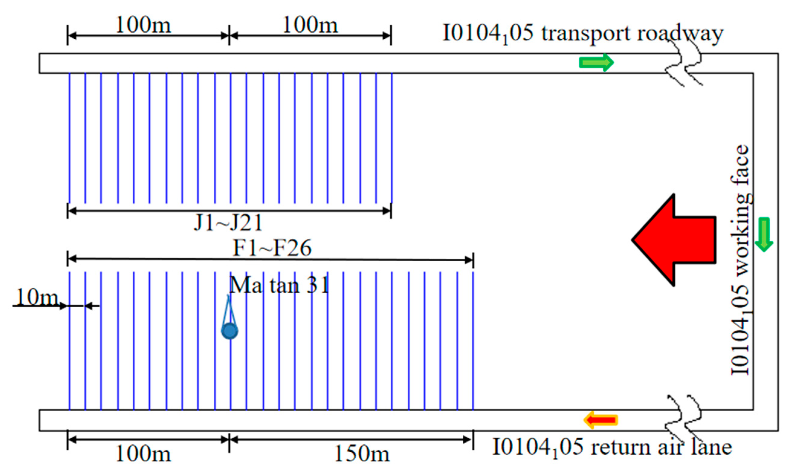
In view of the current technology and equipment limitations of coal seam hydrogen sulfide content testing [41,42]. To obtain the distribution law of coal seam gas and hydrogen sulfide in the area affected by abandoned oil wells, by measuring the gas and hydrogen sulfide gas concentration in coal seam boreholes in the area affected by abandoned oil wells, the distribution law of gas and hydrogen sulfide can be indirectly reflected. With the Ma tan 31 abandoned oil and the center, 26 boreholes were constructed within 100~150 m of the I0104105 return airway along the strike. Twenty-one drilling holes were constructed within 100 m before and after the I0104105 transportation lane along the strike. After the drilling was completed, the holes were immediately plugged, and after the gas escaped and balanced in the holes, on-site sampling tests and ground gas sample analysis were carried out.
The layout diagram of the gas concentration test borehole is shown in Figure 6.
The oil-bearing strata and coal-bearing strata in the Shuangma coal minefield are the same set of strata. The roof of the coal seam contains a certain amount of oil. The top may include oil-poor strata in terms of content, but it has little impact on the mining face. H2S gushing in local areas of the mining face is mainly affected by poor sealing, damaged casing and within 100 m of coal-bearing strata, and abandoned oil wells with broken casing located in coal-bearing strata. According to the test and analysis results, taking the center of the Ma tan 31 oil wells as the benchmark, the gas concentration distribution law of H2S and gas in each borehole of the return airway and transportation lane of the I0104105 working face is shown in Figure 7 and Figure 8.
According to the analysis results of the borehole gas composition measured in area 100–150 m before and after the strike of the abandoned oil well of Ma tan 31, it can be concluded that the I0104105 working face transportation lane side, along the working face, the closer to the center of the oil well, the higher the hydrogen sulfide gas concentration, but the hydrogen sulfide concentration distribution in the range of −80~80 m shows a gradually increasing trend. On the side of I0104105 transportation lane and return air lane, along the strike direction, within the range of 100~150 m, the area with high hydrogen sulfide concentration is located within 80 m of the cut hole from the center of the oil well to the working face.
Since the coal seam contains gas, the distribution of gas concentration in the borehole on the side of the transportation lane relatively far away from the oil well is relatively stable with little change. The distribution on the side of the return airway where the oil well is relatively close in the horizontal distance shows fluctuations. Still, near the center of the oil well, the gas concentration is relatively high.
Analysis of the Source of Hydrogen Sulfide Gushing
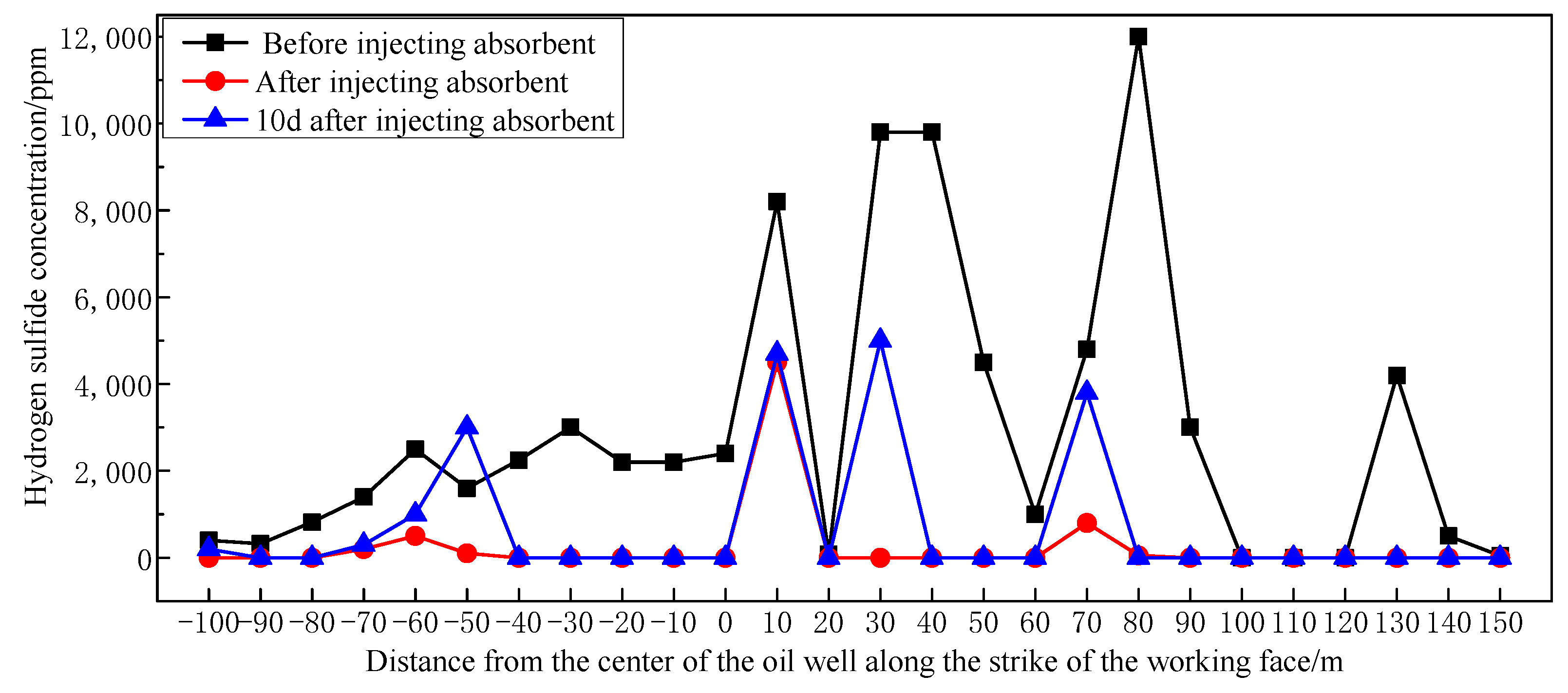
According to the data analysis measured before and after the absorbent injection and ten days later, it was concluded that the hydrogen sulfide absorption effect after the absorbent injection is almost 100%. When the injection of absorbent into the borehole was stopped, it was found that there were signs of rapid rebound of hydrogen sulfide in boreholes F6, F12, F14, and F18, which fully proved that the source of hydrogen sulfide had a supply channel, as shown in Figure 9.
4.2. Determination and Distribution Law of Coal Seam Gas Content
Coal is a porous dual-medium with a lot of pores and cracks [43]. Due to coal pores and crevices, gas generally occurs in coal in two forms, including free and adsorbed states, and is in a state of dynamic equilibrium and constant exchange [44,45].
Under the action of gas pressure, gas, hydrogen sulfide, and other gases existing in abandoned oil wells flow through reverse seepage for an extended period and enter the coal seam from the oil well. Therefore, the gas content of the coal seam in the affected area of the abandoned oil well is generally more significant than that outside the affected area.
Measurement Results of Coal Seam Gas Content
To grasp the distribution law of gas content in the affected area of abandoned oil wells, by drilling test boreholes in the affected area of abandoned oil wells and outside the affected area of abandoned oil wells, the original gas content determination and distribution law of the coal seams in the affected area were analyzed.
Due to the small gas content of the coal seam itself, to avoid the difference in the distribution of coal seam gas content in different mining areas of the working face and the influence of measurement errors, when sampling on-site, it is important to avoid the geological structure area and adopt the method of direct and rapid gas content test as far as possible to make the measurement data accurate and reliable. Five boreholes were constructed in the return airway of the I0104105 working face, and the original gas content of the coal seam in the 120 m area of the abandoned oil well was measured. Each borehole had a depth of 60 m, and coal samples were taken at 20 m, 40 m, and 60 m for testing.
As shown in Figure 10, according to the measurement results, the maximum desorb gas content of coal seam 4-1 in the affected area of the abandoned oil well is 1.28 m3/t.
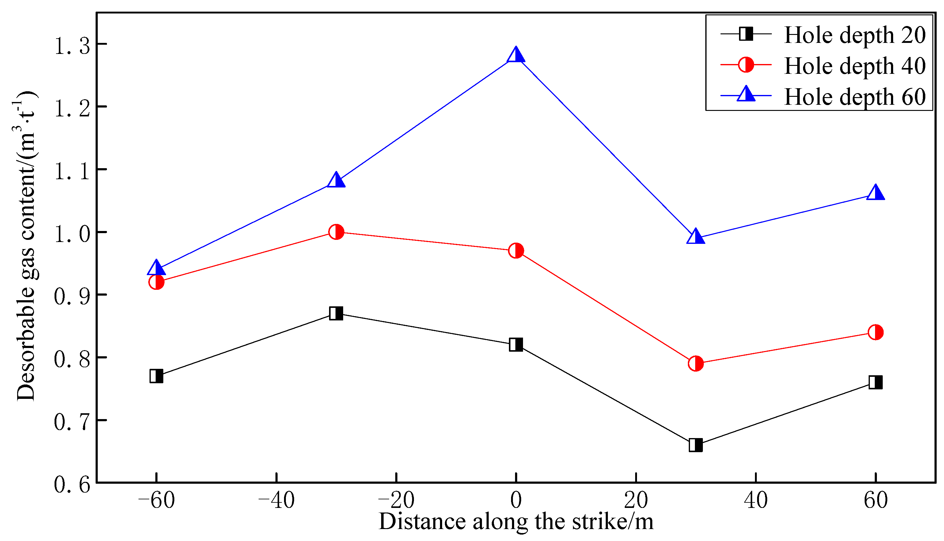
Taking the Ma tan 31 abandoned oil well as the research object, the influence of the abandoned oil well on the distribution of coal seam gas content is studied. By sampling the gas concentration test borehole shown in Figure 6 in the affected area of the abandoned oil well (within the radius of 160 m), the desorb gas content of the coal seam was tested, and the distribution of desorbing gas within the influence range of the abandoned oil well was obtained.
As shown in Figure 11, the closer to the abandoned oil well of Ma tan 31, the higher the desorb gas content of the coal seam. The distribution of coal seam gas content in the affected area of abandoned oil wells along the distance from the center of the oil well shows a decreasing power function trend. Through data fitting, the distribution model of coal seam desorb gas content can be obtained, as shown by Equation (1) [46]:
where is the desorb gas content of the 4-1 coal seam, m3/t, is the radial distance from the center of the abandoned oil well, m.
To verify the influence of abandoned oil wells on coal seam gas content distribution, three boreholes at 100, 150, and 200 m south of the 05B4 drilling field in the return airway of the I0104106 working face (the distance between the borehole and the abandoned oil well is more than 300 m) were constructed with a drilling depth of 80 m, and coal is used at a depth of 40, 60, and 80 m, respectively. Direct testing of the coal seam gas content of the sample shows that the maximum desorb gas content of coal seam 4-1 outside the affected area of abandoned oil wells is 0.72 m3/t (average value 0.64 m3/t).
Therefore, the desorb gas content of the coal seam in the affected area of the abandoned oil well is generally more significant than the desorb gas content of the coal seam outside the affected area of the abandoned oil well. However, due to the relatively small gas content of coal seam 4-1 in Shuangma coal mine, after fully considering the differences in coal seam gas content distribution in different mining areas and reducing errors, abandoned oil wells have a particular impact on coal seam gas content, but the degree of effects is relatively small.
5. The Law of Harmful Gas Gushing
5.1. Investigation on Distribution Law of Gas and Hydrogen Sulfide
The coal body is a porous dual-medium that is rich in pores and cracks. Therefore, the gas occurs in the coal body in two forms: free and adsorbed [47,48]. They are mainly adsorbed and in a dynamic equilibrium state. Regarding the occurrence of hydrogen sulfide in coal seams, relevant scholars have carried out coal adsorption experiments on CO2, CH4, and N2 [49,50]. The results show that the adsorption capacity of adsorbed substances increases with the increase in gas boiling point. Since the lowest boiling point of H2S gas is −60.33 °C, which is higher than CO2, CH4, N2, and other gases, coal has a more substantial adsorption capacity for H2S than the above gas [51].
At the same time, because the polarization rate of hydrogen sulfide 3.64 × 10⁻³⁰ m3 is greater than that of methane gas 2.60 × 10⁻³⁰ m3, the adsorption capacity of hydrogen sulfide gas is more vital than that of methane gas coal [52]. According to the actual measurement results of the attenuation law of hydrogen sulfide emission in the area affected by abandoned oil wells during the tunneling and mining of the I0104105 working face of Shuang Ma coal mine, it is concluded that after the coal seam is mined, the escape of hydrogen sulfide will be accelerated. Still, it will be emitted when coal cutting is stopped. The hydrogen sulfide decreases rapidly and quickly decays until no hydrogen sulfide is detected.
Therefore, it is further proved that the hydrogen sulfide in the coal body mainly exists in an adsorbed state [53,54]. It is not easy to release the hydrogen sulfide in the adsorbed state in the coal body without the effect of considerable energy. In addition, studies have shown that some hydrogen sulfide gas exists in a free state in the coal body. Because hydrogen sulfide gas is easily soluble in water, hydrogen sulfide also occurs in a water-soluble state to form sulfuric acid or sulfurous acid. The attenuation law of hydrogen sulfide gushing after mining is shown in Figure 12.
5.2. Investigation on the Influence Scope of Gas and H2S Mining and Gushing
Taking the abandoned oil well Ma tan 31 as the research object, the gas, and hydrogen sulfide emission distribution law during the mining of the working face through the area affected by the abandoned oil well was studied. The abandoned oil well is 375 m away from the I0104105 working face. The maximum hydrogen sulfide concentration measured by boreholes in the affected area of the abandoned oil well reaches 0.012, and the maximum desorb gas content is 1.28 m3/t. At the initial mining stage, the air distribution volume is about 1260 m3/min, and after the return air gas concentration increases, the air distribution volume is adjusted to 1800–2300 m3/min.
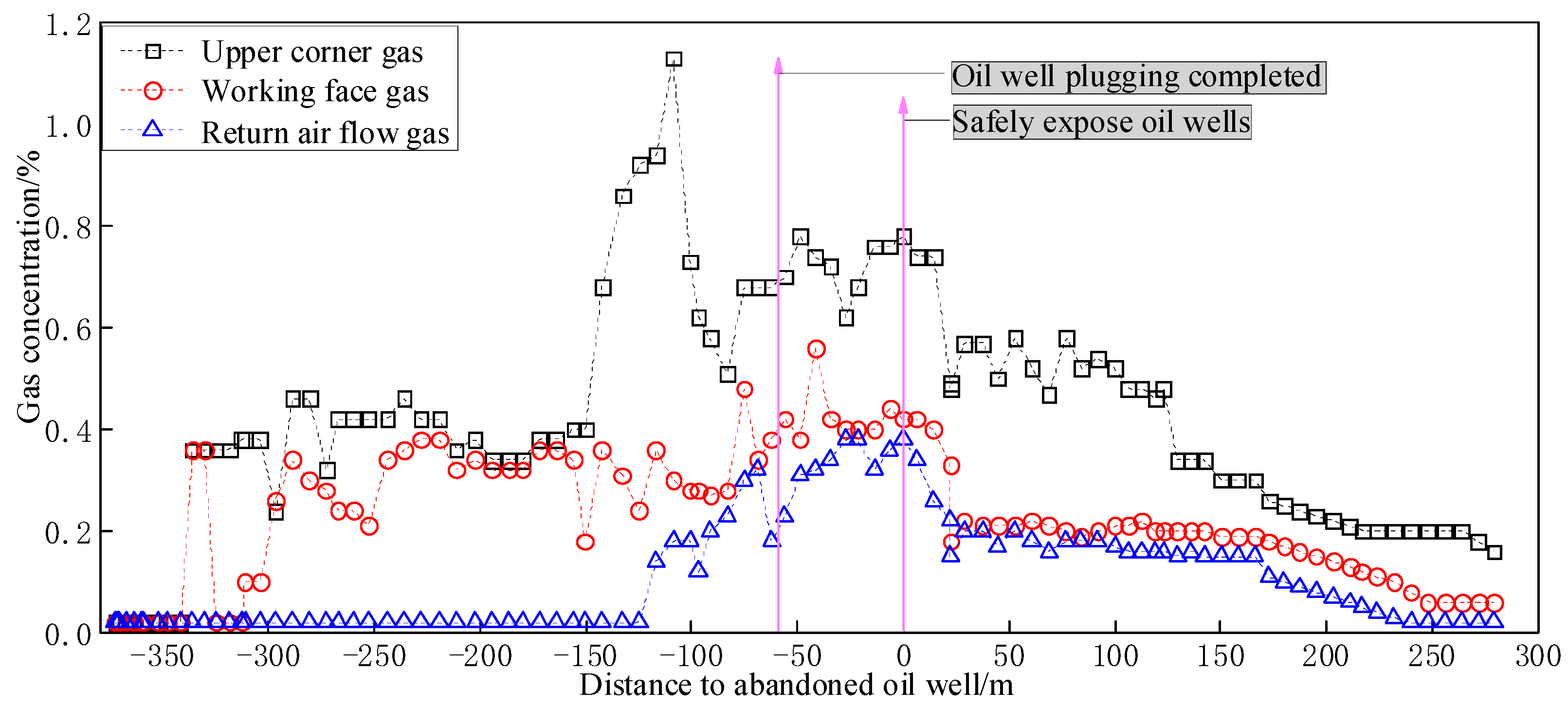
As shown in Figure 13, according to the collected field data, before the working face is advanced to the abandoned oil well, the gas concentration rises. As the working face advances away from the abandoned oil well, the gas concentration decreases. Affected by abandoned oil wells, there is abnormal gas emission in the upper corners of the working surface. It reaches the maximum value before approaching the center of the oil well.
In the areas before and after passing through the center of the oil well, the gas concentration in the working face and the return airway has an increasing trend. The abandoned oil well of Ma tan 31 is an open hole with no casing, and ground plugging has not been carried out in advance. The gas in the oil and gas formation penetrates the coal-measure formation through the cracks and is adsorbed in the coal–rock layer. The gas in the coal–rock layer is affected by mining, with a large amount of escaping ito the mining space.
As shown in Figure 14, from the beginning of recovery to the 150 m of the oil well, the working face tends to have a relatively large hydrogen sulfide gushing concentration. The average gushing concentration is between 40 × 10−6 and 350 × 10−6 ppm. When the working face starts to be mined, the coal seam is affected by mining, and a large amount of hydrogen sulfide gushes out. After that, the concentration of hydrogen sulfide gushes out to maintain a high concentration value and fluctuates. After the oil well is blocked until the working face is far away from the oil well, the sulfide concentration of hydrogen gushing gradually decreases.
As shown in Figure 15, the gas and H2S gushing trend of the I0104105 working face when passing through the Ma tan 31 abandoned oil well can be obtained. Combining the location of H2S during the excavation and the distribution of gas and H2S within the affected area of abandoned oil wells, it can be concluded that:
(1) Before the working face passes the abandoned oil well, the concentration of gas and H2S rises. As the working face is far away from the abandoned oil well, the concentration of gas and H2S shows a downward trend.
Since the abandoned oil well of Ma tan 31 is an open hole without casing, and the ground has not been plugged in advance, the gas and H2S of the oil and gas formation invade into the coal-measure formation through the fissures and are adsorbed in the coal seam. When the coal seam is gradually moving forward, a large amount of toxic and harmful gas slowly escapes to the mining space.
(2) When the abandoned oil well of Ma tan 31 is about 376 m away from the I0104105 working face, according to the changing trend of H2S concentration, H2S appeared when the I0104105 working face started to advance, which is completely consistent with the gas source statistics during the tunneling of the aforementioned working face. When the I0104105 working face passes through the Ma tan 31 abandoned well, the impact range of the Ma tan 31 abandoned oil well on strike is more than 600 m.
(3) In the I0104105 working face, the gas and H2S concentration exceeded the limit in varying degrees during tunneling and coal mining. At the same time, gas was exceeded in the upper corner after advancing 80 m on the working face, and the highest volume fraction reached 1.13%. Based on the changes in the location and concentration of gas and hydrogen sulfide during excavation and coal mining, as well as long-term tracking and determination of gas and hydrogen sulfide, it is proposed that the affected area of the Ma tan 31 abandoned oil well has a “300 m radius of escape circle”, that is the abandoned oil well. As the center of the circle, the diffusion radius of H2S and other harmful gases in the oil well is above 300 m.
6. Conclusions
(1) According to the structure of the oil well and the positional relationship with the coal seam, the source of hydrogen sulfide in the affected area of the abandoned oil well in the coal mining face of Shuangma Coal Mine is mainly affected by the abandoned oil well, and the casing of the oil well is damaged and within 100 m below the coal-bearing formation, and when the casing is damaged and located in the coal-bearing formation, it will have a greater impact on the working face.
(2) The hydrogen sulfide in the coal in the affected area of the abandoned oil well mainly exists in the adsorbed state. The petroleum reservoir contains H2S, CH4 and other gases with a certain pressure (concentration), which gradually escape to the coal-measure strata after a long period of time and are adsorbed in the coal-measure formation. In the coal seam, a large amount of desorption is released under the influence of mining. The distribution of coal seam desorbs gas content along the distance from the center of the oil well, showing a decreasing trend in the power function.
(3) The study shows that the gas and H2S in the affected area of the Ma tan 31 abandoned oil well in Shuangma coal mine have an impact radius of at least 300 m on the I0104105 working face. The hypothesis of gas “escape circle” distribution in the affected area of abandoned oil wells are proposed. However, due to the influence of coal physical properties, hydrogen sulfide adsorption characteristics, geological structure, and other factors, the distribution of gas and H2S in the affected area of abandoned oil wells and the scope of influence may be different in the next step. The above factors will be comprehensively considered in further in-depth research.
(4) The concentration distribution and variation trend of coal seam gas and hydrogen sulfide gushing in the area affected by abandoned oil wells are generally consistent with the distribution and changing trend of coal seam gas content distribution. The hydrogen sulfide gushing has a greater impact on the working face. Due to the particularity of the occurrence of hydrogen sulfide in the coal seam, the problem of gushing control cannot be solved only by ventilation and dilution. Active and passive control methods such as injection of absorbing liquid into the coal seam before mining and spray absorption during mining can be adopted.
Author Contributions
Conceptualization, H.M.; writing—original draft preparation, H.M. and X.W.; writing—review and editing, H.M., X.W., X.Q., K.G. and S.L.; supervision, H.M., X.W. and X.Q. All authors have read and agreed to the published version of the manuscript.
Funding
Project (52104194) supported by the National Science Foundation for Distinguished Young Scholars of China and project (52074148) supported by Natural Science Foundation of China.
Institutional Review Board Statement
Not applicable.
Informed Consent Statement
Not applicable.
Data Availability Statement
The datasets generated during and analyzed during the current study are available from the corresponding author on reasonable request.
Conflicts of Interest
The authors declare no conflict of interest.
References
- Raimi, D.; Krupnick, A.J.; Shah, J.S. Decommissioning orphaned and abandoned oil and gas wells: New estimates and cost drivers. Environ. Sci. Techn. 2021, 55, 10224–10230. [Google Scholar] [CrossRef] [PubMed]
- Romanzo, N.N. Locating Undocumented Abandoned Oil and Gas Wells. Master’s Thesis, State University of New York at Binghamton, New York, NY, USA, 18 March 2020. [Google Scholar]
- Lebel, E.D.; Lu, H.S.; Vielstädte, L. Methane emissions from abandoned oil and gas wells in California. Environ. Sci. Techn. 2020, 54, 14617–14626. [Google Scholar] [CrossRef] [PubMed]
- Riddick, S.N.; Mauzerall, D.L.; Celia, M.A. Variability observed over time in methane emissions from abandoned oil and gas wells. Int. J. Greenh. Gas Control 2020, 100, 103116. [Google Scholar] [CrossRef]
- Zanocco, C.; Boudet, H.; Nilson, R. Place, proximity, and perceived harm: Extreme weather events and views about climate change. Clim. Chang. 2018, 149, 349–365. [Google Scholar] [CrossRef]
- Luca, C.; Antonio, Z. Constraints of fossil fuels depletion on global warming projections. Energy Policy. 2011, 39, 5026–5034. [Google Scholar]
- Zhang, W.H.; Yan, Q.Y.; Yuan, J.H.; He, G.; Teng, T.L.; Zhang, M.J.; Zeng, Y. A realistic pathway for coal-fired power in China from 2020 to 2030. J. Clean. Prod. 2020, 275, 122859. [Google Scholar] [CrossRef]
- Zhang, G.; Suo, Y.L.; Xu, G. Distribution Characteristics of H2S in Coal Seams around Abandoned Oil Wells and Division of Its Mining Influence Range in Shuangma Coal Mine. Sci. Technol. Eng. J. Sci. Technol. Eng. 2021, 21, 5759–5766. Available online: https://kns.cnki.net/kcms/detail/detail.aspx?FileName=KXJS202114017&DbName=CJFQ2021 (accessed on 6 January 2021). (In Chinese).
- Zhang, P.; Lan, H.Q.; Yu, M. Reliability evaluation for ventilation system of gas tunnel based on Bayesian network. Tunn. Undergr. Space Technol. 2021, 112, 103882. [Google Scholar] [CrossRef]
- Wang, G.F.; Xu, Y.X.; Ren, H.W. Intelligent and ecological coal mining as well as clean utilization technology in China: Review and prospects. Int. J. Min. Sci. Technol. 2019, 29, 161–169. [Google Scholar] [CrossRef]
- Wang, K.; Jiang, S.G.; Zhang, W.Q.; Wu, Z.Y.; Shao, H.; Kou, L.W. Destruction mechanism of gas explosion to ventilation facilities and automatic recovery technology. Int. J. Min. Sci. Technol. 2012, 22, 417–422. [Google Scholar] [CrossRef]
- Huang, D.; Liu, J.; Deng, L.J. A hybrid-encoding adaptive evolutionary strategy algorithm for windage alteration fault diagnosis. Process Saf. Environ. Prot. 2020, 136, 242–252. [Google Scholar] [CrossRef]
- Gao, K.; Deng, L.J.; Liu, J.; Wen, L.X.; Wong, D.; Liu, Z.Y. Study on Mine Ventilation Resistance Coefficient Inversion Based on Genetic Algorithm. Arch. Min. Sci. 2018, 63, 813–826. [Google Scholar]
- Hu, J.H.; Zhao, Y.; Zhou, T.; Ma, S.W.; Wang, X.L.; Zhao, L. Multi-factor influence of cross-sectional airflow distribution in roadway with rough roof. J. Cent. South Univ. 2021, 28, 2067–2078. [Google Scholar] [CrossRef]
- Mayala, L.P.; Veiga, M.M.; Khorzoughi, M.B. Assessment of mine ventilation systems and air pollution impacts on artisanal tanzanite miners at Merelani, Tanzania. J. Clean. Prod. 2016, 116, 118–124. [Google Scholar] [CrossRef]
- Liang, P.Y.; Han, Y.; Zhang, Y.Y.; Wen, Y.T.; Gao, Q.F.; Meng, J. Novel non-destructive testing method using a two-electrode planar capacitive sensor based on measured normalized capacitance values. Measurement 2021, 167, 108455. [Google Scholar] [CrossRef]
- Rodriguez-Vega, M.; Canudas-de-Wit, C.; Fourati, H. Location of turning ratio and flow sensors for flow reconstruction in large traffic networks. Transp. Res. Part B Methodol. 2019, 121, 21–40. [Google Scholar] [CrossRef]
- Hu, X.; Han, Y.M.; Yu, B.; Geng, Z.Q.; Fan, J.Z. Novel leakage detection and water loss management of urban water supply network using multiscale neural networks. J. Clean. Prod. 2021, 278, 123611. [Google Scholar] [CrossRef]
- Lau, P.-W.; Cheung, B.-Y.; Lai, W.-L.; Sham, J.-C. Characterizing pipe leakage with a combination of GPR wave velocity algorithms. Tunn. Undergr. Space Technol. 2021, 109, 103740. [Google Scholar]
- Liang, L.P.; Xu, K.J.; Wang, X.F.; Zhang, Z.; Yang, S.L.; Zhang, R. Statistical modeling and signal reconstruction processing method of EMF for slurry flow measurement. Measurement 2014, 54, 1–13. [Google Scholar] [CrossRef]
- Lu, H.F.; Iseley, T.; Behbahani, S.; Fu, L.D. Leakage detection techniques for oil and gas pipelines: State-of-the-art. Tunn. Undergr. Space Technol. 2020, 98, 103249. [Google Scholar] [CrossRef]
- Aida-zade, K.R.; Ashrafova, E.R. Localization of the points of leakage in an oil main pipeline under nonstationary conditions. J. Eng. Phys. Thermophys. 2012, 85, 1148–1156. [Google Scholar] [CrossRef]
- Zhang, Z.W.; Hou, L.F.; Yuan, M.Q.; Fu, M.; Qian, X.M.; Duanmu, W.; Li, Y.Z. Optimization monitoring distribution method for gas pipeline leakage detection in underground spaces. Tunn. Undergr. Space Technol. 2020, 104, 103545. [Google Scholar] [CrossRef]
- Santos, R.B.; de Sousa, E.O.; da Silva, F.V.; da Cruz, S.L.; Fileti, A.M.F. Detection and on-line prediction of leak magnitude in a gas pipeline using an acoustic method and neural network data processing. Braz. J. Chem. Eng. 2014, 31, 145–153. [Google Scholar] [CrossRef]
- Li, J.; Li, Y.L.; Huang, X.J.; Ren, J.H.; Feng, H.; Zhang, Y.; Yang, X.X. High-sensitivity gas leak detection sensor based on a compact microphone array. Measurement 2021, 174, 109017. [Google Scholar] [CrossRef]
- Singh, K.R.; Dutta, R.; Kalamdhad, A.S.; Kumar, B. An investigation on water quality variability and identification of ideal monitoring locations by using entropy based disorder indices. Sci. Total Environ. 2019, 647, 1444–1455. [Google Scholar] [CrossRef]
- Huang, D.; Liu, Y.; Liu, Y.H.; Song, Y.; Hong, C.S.; Li, X.Y. Identification of sources with abnormal radon exhalation rates based on radon concentrations in underground environments. Sci. Total Environ. 2022, 807, 150800. [Google Scholar] [CrossRef]
- Castillo, E.; Jiménez, P.; Menendez, J.M.; Conejo, A.J. The Observability Problem in Traffic Models: Algebraic and Topological Methods. IEEE Trans. Intell. Transp. Syst. 2008, 9, 275–287. [Google Scholar] [CrossRef]
- Castillo, E.; Calviño, A.; Lo, H.K.; Menéndez, J.M.; Grande, Z. Non-planar hole-generated networks and link flow observability based on link counters. Transp. Res. Part B Methodol. 2014, 68, 239–261. [Google Scholar] [CrossRef]
- Rinaudo, P.; Paya-Zaforteza, I.; Calderón, P.A. Improving tunnel resilience against fires: A new methodology based on temperature monitoring. Tunn. Undergr. Space Technol. 2016, 52, 71–84. [Google Scholar] [CrossRef]
- Balaji, S.; Anitha, M.; Rekha, D.; Arivudainambi, D. Energy efficient target coverage for a wireless sensor network. Measurement 2020, 165, 108167. [Google Scholar] [CrossRef]
- Li, Y.T.; Bao, T.F.; Chen, H.; Zhang, K.; Shu, X.S.; Chen, Z.X.; Hu, Y.H. A large-scale sensor missing data imputation framework for dams using deep learning and transfer learning strategy. Measurement 2021, 178, 109377. [Google Scholar] [CrossRef]
- Ng, M. Synergistic sensor location for link flow inference without path enumeration: A node-based approach. Transp. Res. Part B Methodol. 2012, 46, 781–788. [Google Scholar] [CrossRef]
- He, S.X. A graphical approach to identify sensor locations for link flow inference. Transp. Res. Part B Methodol. 2013, 51, 65–76. [Google Scholar] [CrossRef]
- Muduli, L.; Jana, P.K.; Mishra, D.P. A novel wireless sensor network deployment scheme for environmental monitoring in longwall coal mines. Process Saf. Environ. Prot. 2017, 109, 564–576. [Google Scholar] [CrossRef]
- Wang, K.; Jiang, S.G.; Wu, Z.Y.; Shao, H.; Zhang, W.Q.; Pei, X.D.; Cui, C.B. Intelligent safety adjustment of branch airflow volume during ventilation-on-demand changes in coal mines. Process Saf. Environ. Prot. 2017, 111, 491–506. [Google Scholar] [CrossRef]
- Song, Y.W.; Yang, S.Q.; Hu, X.C.; Song, W.X.; Sang, N.W.; Cai, J.W.; Xu, Q. Prediction of gas and coal spontaneous combustion coexisting disaster through the chaotic characteristic analysis of gas indexes in goaf gas extraction. Process Saf. Environ. Prot. 2019, 129, 8–16. [Google Scholar] [CrossRef]
- Lyu, P.Y.; Chen, N.; Mao, S.J.; Li, M. LSTM based encoder-decoder for short-term predictions of gas concentration using multi-sensor fusion. Process Saf. Environ. Prot. 2020, 137, 93–105. [Google Scholar] [CrossRef]
- Foorginezhad, S.; Mohseni-Dargah, M.; Firoozirad, K.; Aryai, V.; Razmjou, A.; Abbassi, R.; Garaniya, V.; Beheshti, A.; Asadnia, M. Recent Advances in Sensing and Assessment of Corrosion in Sewage Pipelines. Process Saf. Environ. Prot. 2021, 147, 192–213. [Google Scholar] [CrossRef]
- Hu, Y.N.; Koroleva, O.I.; Krstić, M. Nonlinear control of mine ventilation networks. Syst. Control Lett. 2003, 49, 239–254. [Google Scholar] [CrossRef]
- Khan, K.S.; Tariq, M. Accurate Monitoring and Fault Detection in Wind Measuring Devices through Wireless Sensor Networks. Sensors 2014, 14, 22140–22158. [Google Scholar] [CrossRef] [Green Version]
- Sun, J.P.; Tang, L.; Li, C.S.; Zhu, N.; Zhang, B. Application of air-volume Proportion rule in optimal placement of gas sensor in mine. J. China Coal Soc. 2008, 33, 1126–1130. (In Chinese) [Google Scholar]
- Zhao, D.; Liu, J.; Pan, J.T.; Li, Z.X. Application study of air velocity fault source diagnosis technology for ventilation system in Daming Mine. Chin. J. Saf. Environ. 2012, 12, 204–207. (In Chinese) [Google Scholar]
- Dong, X.L.; Chen, S.; Zhao, D.; Pan, J.T. Study on Application of Minimum Tree Principle in Layout of Wind Speed Sensor in Mine. Chin. World Sci-Tech R D 2015, 37, 680–683. (In Chinese) [Google Scholar]
- Liang, S.H.; He, J.; Zheng, H.; Sun, R.H. Research on the HPACA Algorithm to Solve Alternative Covering Location Model for Methane Sensors. Procedia Comput. Sci. 2018, 139, 464–472. [Google Scholar] [CrossRef]
- Zhao, D.; Zhang, H.; Pan, J.T. Solving Optimization of A Mine Gas Sensor Layout Based on A Hybrid GA-DBPSO Algorithm. IEEE Sens. J. 2019, 19, 6400–6409. [Google Scholar] [CrossRef]
- Wu, C.Q.; Wang, L. On Efficient Deployment of Wireless Sensors for Coverage and Connectivity in Constrained 3D Space. Sensors 2017, 17, 2304. [Google Scholar] [CrossRef] [Green Version]
- Semin, M.A.; Levin, L.Y. Stability of air flows in mine ventilation networks. Process Saf. Environ. Prot. 2019, 124, 167–171. [Google Scholar] [CrossRef]
- Liu, J.; Jiang, Q.H.; Liu, L.; Wang, D.; Huang, D.; Deng, L.J.; Zhou, Q.C. Resistance variant fault diagnosis of mine ventilation system and position optimization of wind speed sensor. J. China Coal Soc. 2021, 46, 1907–1914. (In Chinese) [Google Scholar]
- Jia, J.Z.; Liu, J.; Geng, X.W. Mathematical model of mine ventilation simulation system. J. Liaoning Tech. Univ. 2003, 22 (Suppl. S1), 88–90. (In Chinese) [Google Scholar]
- Dong, L.; Hu, Q.; Tong, X. Velocity-free MS/AE source location method for three-dimensional hole containing structures. Engineering 2020, 6, 827–834. [Google Scholar] [CrossRef]
- Dong, L.; Tong, X.; Ma, J. Quantitative investigation of tomographic effects in abnormal regions of complex structures. Engineering 2021, 7, 1011–1022. [Google Scholar] [CrossRef]
- Dong, L.; Tong, X.; Hu, Q.; Tao, Q. Empty region identification method and experimental verification for the two-dimensional complex structure. Int. J. Rock Mech. Min. Sci. 2021, 147, 104885. [Google Scholar] [CrossRef]
- Dong, L.J.; Chen, Y.C.; Sun, D.Y.; Zhang, Y.H. Implications for rock instability precursors and principal stress direction from rock acoustic experiments. Int. J. Min. Sci. Technol. 2021, 31, 789–798. [Google Scholar] [CrossRef]
Figure 1.
Emission position of H2S on driving face.

Figure 2.
Schematic diagram of detection drilling layout.

Figure 3.
Records of underground exposure of Ma tan 31 oil well.

Figure 4.
Schematic diagram of the wellbore structure of an abandoned oil well. (a) No casing (open hole); (b) Broken casing; (c) Reinforced wells are not toghtly sealed by ceme.
Figure 4.
Schematic diagram of the wellbore structure of an abandoned oil well. (a) No casing (open hole); (b) Broken casing; (c) Reinforced wells are not toghtly sealed by ceme.


Figure 5.
The positional relationship between the Ma tan 31 oil well and the coal-measure strata.

Figure 6.
H2S concentration test drilling layout of Ma tan 31 oil well.

Figure 7.
Distribution law of gas concentration in each borehole at the side of the transportation road in I0104105 working face.
Figure 7.
Distribution law of gas concentration in each borehole at the side of the transportation road in I0104105 working face.

Figure 8.
Gas concentration distribution law in each borehole on the side of return airway in I0104105 working face.
Figure 8.
Gas concentration distribution law in each borehole on the side of return airway in I0104105 working face.

Figure 9.
The trend diagram of hydrogen sulfide concentration before and after the absorbent injection in the abandoned oil well of Ma tan 31.
Figure 9.
The trend diagram of hydrogen sulfide concentration before and after the absorbent injection in the abandoned oil well of Ma tan 31.

Figure 10.
Variation law of gas content near Ma tan 31 abandoned oil well.

Figure 11.
The distribution law of coal seam desorb gas content along the radial direction.

Figure 12.
The attenuation law of hydrogen sulfide gushing during the mining process of the working face.
Figure 12.
The attenuation law of hydrogen sulfide gushing during the mining process of the working face.

Figure 13.
Gas concentration change curve during the period of the impact of the I0104105 working face passing through the Ma tan 31 abandoned oil well.
Figure 13.
Gas concentration change curve during the period of the impact of the I0104105 working face passing through the Ma tan 31 abandoned oil well.

Figure 14.
The concentration change curve of hydrogen sulfide emission during the I0104105 working face passing through the Ma tan 31 abandoned oil well.
Figure 14.
The concentration change curve of hydrogen sulfide emission during the I0104105 working face passing through the Ma tan 31 abandoned oil well.

Figure 15.
The trend diagram of absolute gas and hydrogen sulfide emission changes in the I0104105 working face passing through the Ma tan 31 abandoned oil well.
Figure 15.
The trend diagram of absolute gas and hydrogen sulfide emission changes in the I0104105 working face passing through the Ma tan 31 abandoned oil well.


Table 1.
Statistics of H2S emission at different positions of the tunneling face.
| Location and Location | Gushing Gas Volume Fraction/10−6 | Actual Site Situation |
|---|---|---|
| I0104104 return air tunnel excavation, 404–508 m away from no. 5 connecting lane, 212 m away from ma tan 30 oil well | -- | Local roof fissure oil seepage |
| I0104104 return air tunnel excavation, 158 m away from ma tan 30 oil well | 3.5~15.0 | The smell of rotten eggs in the lane |
| I0104105 return air tunnel excavation, 331 m away from no. 5 connecting lane, 251 m away from ma tan 30 oil well | 1.5~50.0 | Smell of rotten eggs |
| I0104105 transport lane excavation, 627 m away from no. 2 ventilation measures lane, 150,435 m away from ma tan 30 and 31 oil wells | 60~80 | The volume fraction of H2S gushing out at 445 m is 45 × 10−6 |
| I0104106 excavation of return air lane, 296 and 313 m away from ma tan 30 and ma tan 31 oil wells | 60~80 | H2S gushes out during tunneling |
Table 2.
Detecting results of borehole gas detection in return airway of I0104105 working face.
| Detection Location | Inclination/(°) | Length/m | Aperture/mm | μ (H2S)/10−6 |
|---|---|---|---|---|
| K1 drilling | 7 | 40 | 94 | 38,033.52 |
| K2 drilling | 6 | 35 | 94 | 25,599.14 |
| The borehole is located 41 m south of the abandoned oil well of ma tan 31 | - | - | - | 10,200.00 |
Table 3.
Analysis results of borehole gas 41 m to the south from the abandoned oil well of ma tan 31.
Table 3.
Analysis results of borehole gas 41 m to the south from the abandoned oil well of ma tan 31.
| Serial Number | Analysis Project | Analysis Result/% | Serial Number | Analysis Project | Analysis Result/% |
|---|---|---|---|---|---|
| 1 | H2 | <0.01 | 7 | COS | <0.005 |
| 2 | CO2 | 0.90 | 8 | CH4 | 75.51 |
| 3 | O2 | 1.98 | 9 | C2 alkanes | 0.46 |
| 4 | N2 | 21.13 | 10 | C2 alkanes | 0.01 |
| 5 | CO | <0.01 | 11 | C3 olefin | <0.01 |
| 6 | H2S | 1.02 | 12 | C4 alkanes | <0.01 |
Table 4.
Abandoned oil wells pass through the formation and statistics of thickness.
| Oil Well | Layer Thickness/m | Layer Thickness/m | Cumulative Depth/m | ||||
|---|---|---|---|---|---|---|---|
| Jurassic | Triassic | ||||||
| Fourth Series | Paleogene | Stability Group | Zhiluo Formation | Yan’an Formation | Yan’an Formation | ||
| Ma tan 30 | 10 | 81.8 | - | 134.7 | 344.7 | 666 | 1237.2 |
| Ma tan 30 | 15 | 64.0 | 63.1 | 67.9 | 290.0 | 666 | 1166.0 |
Publisher’s Note: MDPI stays neutral with regard to jurisdictional claims in published maps and institutional affiliations. |
© 2022 by the authors. Licensee MDPI, Basel, Switzerland. This article is an open access article distributed under the terms and conditions of the Creative Commons Attribution (CC BY) license (https://creativecommons.org/licenses/by/4.0/).
Share and Cite
MDPI and ACS Style
Wang, X.; Ma, H.; Qi, X.; Gao, K.; Li, S. Study on the Distribution Law of Coal Seam Gas and Hydrogen Sulfide Affected by Abandoned Oil Wells. Energies 2022, 15, 3373. https://doi.org/10.3390/en15093373
AMA Style
Wang X, Ma H, Qi X, Gao K, Li S. Study on the Distribution Law of Coal Seam Gas and Hydrogen Sulfide Affected by Abandoned Oil Wells. Energies. 2022; 15(9):3373. https://doi.org/10.3390/en15093373
Chicago/Turabian StyleWang, Xiaoqi, Heng Ma, Xiaohan Qi, Ke Gao, and Shengnan Li. 2022. "Study on the Distribution Law of Coal Seam Gas and Hydrogen Sulfide Affected by Abandoned Oil Wells" Energies 15, no. 9: 3373. https://doi.org/10.3390/en15093373
Note that from the first issue of 2016, this journal uses article numbers instead of page numbers. See further details here.