
Cascade Control Method of Sliding Mode and PID for PEMFC Air Supply System


1
School of Vehicle Engineering, Chongqing University of Technology, Chongqing 400054, China
2
School of Electrical Engineering, Chongqing University, Chongqing 400044, China
3
Chongqing Changan New Energy Vehicle Technology Co., Ltd., Chongqing 400023, China
4
School of Automotive Engineering, Harbin Institute of Technology, Weihai 264209, China
*
Author to whom correspondence should be addressed.
Energies 2023, 16(1), 228; https://doi.org/10.3390/en16010228
Submission received: 13 November 2022
/
Revised: 15 December 2022
/
Accepted: 21 December 2022
/
Published: 25 December 2022
(This article belongs to the Topic Battery Design and Management)
Abstract
:Proton exchange membrane fuel cells (PEMFC) are vulnerable to oxygen starvation when working under variable load. To address these issues, a cascade control strategy of sliding mode control (SMC) and Proportion Integration Differentiation (PID) control is proposed in this study. The goal of the control strategy is to enhance the PEMFC’s net power by adjusting the oxygen excess ratio (OER) to the reference value in the occurrence of a load change. In order to estimate the cathode pressure and reconstruct the OER, an expansion state observer (ESO) is developed. The study found that there is a maximum error of about 2200Pa between the estimated cathode pressure and the actual pressure. Then the tracking of the actual OER to the reference OER is realized by the SMC and PID cascade control. The simulation study, which compared the control performance of several methods—including PID controller, adaptive fuzzy PID controller and the proposed controller, i.e., the SMC and PID cascade controller—was carried out under various load-changing scenarios. The outcomes demonstrate that the proposed SMC and PID cascade controller method really does have a faster response time. The overshoot is reduced by approximately 3.4% compared to PID control and by about 0.09% compared to fuzzy adaptive PID. SMC and PID cascade control reference OER performs more effectively in terms of tracking compared to PID control and adaptive fuzzy PID control.
1. Introduction
In recent years, the ecological environment has suffered greatly due to factors such as global warming, energy shortages and excessive carbon emissions [1]. Therefore, the research and promotion of renewable energy has become the focus of social attention. PEMFC is a type of power-generating equipment that converts chemical energy directly into electrical energy. Since it has high energy density, stable energy output, environmental friendliness and low operating temperature, among other advantages, it is viewed as a promising energy converter in the fields of aerospace, automotive and other industries [2].
However, PEMFC is a complicated system with strong time-varying, nonlinear and multi-coupling characteristics. Because of its delay characteristics, the air compressor will not respond immediately when the load changes quickly. The output voltage of the PEMFC will drop quickly if the supply air flow is insufficient. If this continues, the proton exchange membranes may degrade, lowering the lifetime of the PEMFC [3,4]. On the other hand, if the air compressor supplies too much airflow, the compressor’s power consumption increases, and the PEMFC’s net output power production declines [5,6]. To ensure the PEMFC supply system’s reliable and effective performance, modern control technology is demanded [7]. The net power and service life of PEMFC are directly affected by the gas supply system. As a result, controlling the oxygen excess ratio (OER) of PEMFC has grown to be a crucial technique. The issue of excess parasitic power brought on due to excessive oxygen in PEMFC ought to be resolved. So researchers have conducted various studies on mechanism modeling and control strategies of air supply system. In terms of mechanism modeling, Pukrushpan constructed a complex ninth-order model [8]; the high-order model includes many states and complex models, making it challenging to design a controller and demanding a large amount of computation. The reliable operation of air compressors, air supply manifolds, humidifiers, coolers, etc. is the basis for guaranteeing the efficient operation of the PEMFC air supply system. The researchers simplified the ninth-order model to a fourth-order model and a third-order model, assuming other subsystems are well controlled in Refs. [9,10]. Through experiments, the reliability and accuracy of the simplified model are verified. The design of the controller is made easier by the simplified model. Many researchers base their studies on the control of the PEMFC oxygen supply system on the simplified third-order model.
For fuel cell gas supply systems, there are already various control techniques available. The LQR (Linear Quadratic Regulator) controller is employed to address the problem of controlling the air compressor voltage in the oxygen supply system, which in turn controls the cathode air intake volume and improves the net power of PEMFC [11,12]. The literature proposes to employ PID parallel control and series control of model predictive control (MPC) and MPC to prevent oxygen starvation and improve the net output power of PEMFC [13,14]. Since the linearized operating points are chosen based on practical factors and particular points are reached within the stacked working range, the accuracy of the linearized model will be impacted when the load dramatically changes. Because linear controllers inevitably introduce linearization mistakes, the effect of linearized control might worsen. Nonlinear control studies have been carried out as a consequence. The OER of the PEMFC gas supply system would be reconstructed by using a higher-order sliding mode observer proposed by Deng et al. Additionally, they employ a cascade adaptive sliding mode control for air compressor voltage to increase PEMFC’s net output power [15]. According to the literature [16], the gas supply system is controlled by a second-order sliding mode control strategy to increase fuel cell net output power and prevent oxygen starvation. A nonlinear controller is designed based on the gas supply system model to control OER through feedback linearization, and the results demonstrate that the proposed nonlinear controller has better transient response in ref. [17]. The OER is adjusted by using PID control and fuzzy PID control on the fourth order oxygen supply model in ref. [18]. However, neural networks are a powerful modeling and control tool that is widely employed in battery warning and fuel cell control [19,20]. In terms of PEMFC control, Damour et.al [21] proposed a model with artificial neural networks. This method enables self-tuning of the PID control strategy; the controller avoids a calculation burden while accounting for the process’ nonlinear behavior. In a word, the various controllers aforementioned have their own advantages in fuel cell control application.
The focus of this work is on the regulation of the OER to obtain the greatest net output power in PEMFC. To solve the difficult challenge of measuring cathode pressure, this method employs an ESO to increase the accuracy of the control model by estimating the cathode pressure. This proposal is based on the application of observers in the field of fuel cells [12,19,22]. This study’s contribution is to control the air compressor’s input voltage by efficiently adjusting the OER to the reference value when the load varies. The oxygen starvation in PEMFC systems is improved by using this method, which also increases the service life of fuel cells.
The rest of this study is as follows: The modeling and control objectives of the PEMFC system are presented in Section 2. The cascade control of sliding mode and PID and ESO are designed in Section 3. The advantages of different control strategies are briefly compared in Section 4. The results are presented in Section 5.
2. PEMFC System Modeling and Control Objective
The components of the air system include air flow meters, air compressors, intercoolers, humidifiers, stacking throttles composed of stack-out throttle pipeline, etc. The cathode air system provides pressure, flow, temperature and air, with suitable humidity participates in the reaction. The system composition is shown in Figure 1.
An object-oriented PEMFC third-order control mechanism model was established in this study to serve as a model for research on air loop coordinated control. The model makes the following acceptable assumptions:
- Suppose all gasses meet the law of ideal gasses;
- Consider the intake gas to be air at standard atmospheric pressure;
- It is assumed that the supply manifold’s intake and outlet temperatures are equivalent;
- Presume that the cathode’s internal gas is ideally humidified, with a 100% humidity;
- Consider that there is only the composition of nitrogen and oxygen in the dry gas;
- Suppose that the anode hydrogen is sufficient and the anode pressure changes with the cathode pressure;
- It is hypothesized that the system humidity and temperature are maintained at the desired value by means of humidifiers and coolers.
2.1. Air Supply System Modeling
2.1.1. Air Compressor Model
The drive motor and air compressor components make up the air compressor. is mainly employed to control air intake air flow. By using motor torque balance equation, the air compressor model is as follows [23].
where is the compressor moment of inertia; is the compressor speed; and , respectively, are the compressor motor drive torque and load torque.
The motor drive torque equation and resisting moment equation for air compressors:
The above expressions: , , are the motor constant; is the motor terminal voltage is motor efficiency; is compressor efficiency; is the specific heat capacity coefficient of air; and are correspondingly inlet air temperature and inlet air pressure; is the compressor outlet flow, which is influenced by the supply manifold pressure and the compressor speed; the details specific is found in Ref [8].
2.1.2. Air Supply Manifold Model
The manifold connecting the fuel cell stack and the air compressor is symbolized by the supply manifold. The dynamic change model of the gas pressure in the supply manifold is built using the law of conservation of energy and the ideal gas law as follows:
where is the air mass flow rate of the cathode inlet; is the volume of the gas supply manifold; R is the air gas constant; is the air molar mass. is air compressor outlet gas temperature; it can be calculated using the formula below.
because there is a small difference in gas pressure between the cathode and the air supply manifold, the gas pressure in the fuel cell stack is relatively low. Employing the linear nozzle equation can aid in reducing calculations.
where is cathode pressure is the supply pipe outlet constant, it reflects the resistance of the pipe to the airflow [9].
2.1.3. Stack Cathode Gas Model
The equation of state for each gas at the cathode is calculated using the rules of mass conservation and ideal gases [21].
where is oxygen molar mass; is nitrogen molar mass; is the stack temperature; is the cathode flow channel volume. The mass flow of incoming and outgoing gas is shown by the symbols and , respectively; is the reaction mass involved in oxygen.
where is the mass fraction of oxygen in the inlet gas; is gas humidity; is the molar fraction of oxygen in the air; is the number of fuel cells in the stack; is the relative humidity of the inlet gas; is saturated water vapor pressure [8]. The mass flow of oxygen and nitrogen out of the cathode of PEMFC is shown below.
is air specific heat ratio; F is Faraday constant; is cathode outlet flow coefficient.
The saturated water vapor pressure is taken into account as a constant value, and only the oxygen and nitrogen in the air are taken into account. The cathode of the stack should also adhere to the following formula:
According to Equations (1)–(17), the state variable is selected to derive the control model and establish a third-order control model as follows [24]:
2.2. Control Objective
The main control goal of this study was to adjust the OER to the reference OER, which is defined as follows:
OER is defined as the ratio between the flow of air entering the cathode and the flow of oxygen consumed by the cathode. The PEMFC stack will suffer from oxygen starvation and significant damage if the OER value is too high, but the air compressor’s power consumption will increase if the OER value is too low, which will reduce the PEMFC’s net output power [25]. Consequently, the main control goal of the gas supply system is to adjust OER to the reference OER and prevent oxygen starvation in PEMFC and improve PEMFC net output power under various loads. The ideal OER fitting curve is in accordance with Ref. [26].
3. Controller and Observer Design
In this section, unmeasurable state variables will be introduced, and ESO will be established for real-time estimate. According to the ESO estimated cathode pressure to reconstruct the OER. SMC and PID cascade control are designed to be employed to complete the tracking of the reference OER.
3.1. Observer Design
OER value is significantly influenced by the cathode pressure and air supply manifold pressure. Since it is difficult to measure the cathode pressure, the ESO must be employed to reconstruct the OER curve to improve the PEMFC’s gas supply regulation’s accuracy. The ESO is structured as follows:
Making , then rewrite it as follows:
The ESO is as follows:
The characteristic polynomial can be designed to be:
where is the value of reconstructed OER and is the value recorded by ESO. In conclusion, Figure 2 shows the actual and estimated values of the cathode pressure as load changes.
The biggest difference between the estimated cathode pressure by ESO and the actual cathode pressure, as shown in Figure 3, is approximately 2200 Pa, which is within the permitted range. The OER can be reconstructed using cathode pressure estimated by the ESO, and the compressor input voltage is controlled by using reconstructed OER.
3.2. Controller Design
Due to its simple structure, low calculation and easy design, second order sliding mode controllers are broadly employed in fuel cell and automotive control. Algorithms like super-twist and twisting are extensively adopted in second-order sliding mode control. Because the super-twist algorithm is different from other second-order sliding modes, the derivative of the sliding model surface does not need to be understood, which lowers the system’s computational complexity. As a result, the super-twist method is chosen to cascade with PID in order to manage the PEMFC gas supply system. The flow chart for the OER control method is illustrated in Figure 4 and the block diagram of SMC and PID cascade control algorithm is given in Figure 5. The air compressor voltage is input ; the error of and is chosen as the sliding model surface ; the control function of the super-twist method is as follows [7]:
The following conditions must be met by , which are constants that guarantee the supertwist algorithm converges in a finite amount of time:
The s fits the required to control although it fluctuates easily. The saturation function Sat(s) is used in place of the S to reduce fluctuation [27].
where is the output of the SMC controller and tracking OER to reference OER is the eventual goal of the SMC and PID cascade, which is designed in response to the real-time feedback from the oxygen supply system and the error of the controller parameters.
PID controllers are commonly employed in engineering because of their simple structure [28]. is equal to zero because the noisy systems are prone to instability when the erroneous rate of change is introduced; is the output of the PID controller; and represents the error between the OER value and the OER reference value.
where and are proportional constants, integral constants and differential constants, respectively.
4. Simulation and Analysis of Results
This section contrasts simulations of PID controller, adaptive fuzzy PID, SMC and PID cascade control [27]. The advantages of fuzzy logic control include quick response times and strong robustness for nonlinear, time-varying and incomplete model systems. Modern control theory’s fuzzy reasoning and linguistic rules are the basis of fuzzy logic control, an advanced control method and new technology. Combining PID and fuzzy logic offers a possibly more potent remedy for the subpar control performance of PID controllers for nonlinear and time-varying systems [28].
Next, several comparative simulations were performed, which proved that the control OER tracks the reference OER under different operating conditions. The load changes of the PEMFC are shown in Figure 6.
PID control, fuzzy adaptive PID control and SMC and PID cascade control are systematically compared and analyzed in simulations with varying loads. OER could be controlled in comparison to the three control strategies, as demonstrated in Figure 7 and Figure 8.
Figure 7 and Figure 8 demonstrate the comparison of OER results between SMC and PID cascade control, PID control and adaptive fuzzy PID control, respectively, where Figure 7 and Figure 8b–d is a local enlarged image. The OER could converge quickly; the control time is approximately 1s. However, the OER is unable to closely match the reference OER because of a steady-state error that cannot be completely eliminated throughout the control process. Figure 7 and Figure 8 illustrate that, based on this issue, the steady-state error of the control approach proposed in this study is lower than that of PID control and adaptive fuzzy PID control. According to the simulation, it can be concluded that SMC and PID cascade control perform better dynamically than PID control and fuzzy adaptive PID control. Hence, the overshoot under fuzzy adaptive PID control is 0.9% higher than the overshoot under SMC and PID cascade control, and the overshoot under PID control is 3.4% higher than that under SMC and PID cascade control. Compared to fuzzy adaptive PID control and PID control, the response time is quicker. PID controller has the advantages of simple control and simple design when PID control and SMC control are combined; the system’s robustness is increased, but jitter is also increased. However, the controller is better able to mitigate the impacts of nonlinearity and time variation on PEMFC gas supply.
Overall, the proposed SMC and PID cascade control has some robustness and good transient tracking performance.
5. Conclusions
For the PEMFC supply system, which is strongly time-varying, nonlinear and multi-coupling, a cascaded control with an ESO-based SMC and PID is proposed to make OER track the reference OER in order to increase the net output power of PEMFC and prolong the service life. A control-centric third-order model is established because the higher-order model is really quite complex. Since the difficulty in measuring cathode pressure, an ESO is developed. The accuracy of the ESO is confirmed by simulation, which demonstrates that there is a maximum error of approximately 2200 Pa between the estimated cathode pressure and the actual value. The overshoot of the proposed SMC and PID cascade control is reduced by about 3.4% and 0.09%, respectively, in comparison to the PID control and adaptive fuzzy PID control strategies. Additionally, simulation comparison results demonstrate that it has a quicker response time and better OER tracking result.
In the future, it needs to be taken into account how the PEMFC’s gas supply system affects net power when stack temperature changes.
Author Contributions
Conceptualization, A.T.; Writing𠅄original draft, L.Y.; Writing—review & editing, T.Z. and Q.Y. All authors have read and agreed to the published version of the manuscript.
Funding
This research was funded by National Natural Science Foundation of China [Grant No. 52277213, 52177210], Chongqing Education Commission of China [Grant No. KJZD-K202201103], Chongqing Science and Technology Commission [Grant No. cstc2021jcyj-msxmX0464] and Shandong Provincial Department of Science and Technology [Grant No. ZR2020ME209].
Data Availability Statement
Not applicable.
Acknowledgments
This work was jointly supported by the National Natural Science Foundation of China (Grant No. 52277213, 52177210), key project of science and technology research program of Chongqing Education Commission of China (Grant No. KJZD-K202201103), Natural Science Foundation of Chongqing, China (Grant No. cstc2021jcyj-msxmX0464) and Natural Science Program of Shandong Province (Grant No. ZR2020ME209).
Conflicts of Interest
The authors declare no conflict of interest.
Appendix A

Table A1.
The main parameters of the third-order model.
Table A2.
The main physical parameters of PEMFC.
| Symbol | Value | Symbol | Value | Symbol | Value | Symbol | Value |
|---|---|---|---|---|---|---|---|
| 381 | 1004 J/Kg/K | ||||||
| 1.0135 bar | 0.0153 | kg/mol | kg/sa | ||||
| 298 K | 0.82 | kg/mol | 0.0124 | ||||
| 353 K | 0.0153 | 0.002 | 1.4 | ||||
| 0.5 | 0.8 | 96485 | 0.02585 | ||||
| 0.98 | 0.02 |
References
- Yuan, J.; Lin, Q.; Chen, S.; Zhao, H.; Xie, X.; Cai, Z.; Zhang, J.; Cheng, T.; Hua, M.; Zhang, R. Influence of global warming and urbanization on regional climate of Megacity: A case study of Chengdu, China. Urban Clim. 2022, 44, 101227. [Google Scholar] [CrossRef]
- Feng, Y.; Dong, Z. Integrated design and control optimization of fuel cell hybrid mining truck with minimized lifecycle cost. Appl. Energy 2020, 270, 115164. [Google Scholar] [CrossRef]
- Fan, Z.; Yu, X.; Yan, M.; Hong, C. Oxygen excess ratio control of PEM fuel cell based on self-adaptive fuzzy PID. IFAC-Pap. OnLine 2018, 51, 15–20. [Google Scholar] [CrossRef]
- Daud, W.R.W.; Rosli, R.E.; Majlan, E.H.; Hamid, S.A.A.; Mohamed, R.; Husaini, T. PEM fuel cell system control: A review. Renew. Energy 2017, 113, 620–638. [Google Scholar] [CrossRef]
- Matraji, I.; Ahmed, F.S.; Laghrouche, S.; Wack, M. Comparison of robust and adaptive second order sliding mode control in PEMFC air-feed systems. Int. J. Hydrogen Energy 2015, 40, 9491–9504. [Google Scholar] [CrossRef]
- Zhang, H.K.; Wang, Y.F.; Wang, D.H.; Wang, Y.L. Adaptive robust control of oxygen excess ratio for PEMFC system based on type-2 fuzzy logic system. Inf. Sci. 2020, 511, 1–17. [Google Scholar] [CrossRef]
- Chen, J.; He, H. Improve hydrogen economy for vehicular fuel cell system via investigation and control of optimal operating oxygen excess ratio. Energy Rep. 2022, 8, 5883–5897. [Google Scholar] [CrossRef]
- Pukrushpan, J.T.; Stefanopoulou, A.G.; Peng, H. Control of Fuel Cell Power Systems: Principles, Modeling, Analysis and Feedback Design; Springer Science & Business Media: Berlin/Heidelberg, Germany, 2004. [Google Scholar]
- Talj, R.J.; Hissel, D.; Ortega, R.; Becherif, M.; Hilairet, M. Experimental validation of a PEM fuel-cell reduced-order model and a moto-compressor higher order sliding-mode control. IEEE Trans. Ind. Electron. 2009, 57, 1906–1913. [Google Scholar] [CrossRef]
- Gruber, J.K.; Bordons, C.; Dorado, F. Nonlinear control of the air feed of a fuel cell. In Proceedings of the 2008 American Control Conference, Seattle, WA, USA, 11–13 June 2008; IEEE: Piscataway, NJ, USA, 2008; pp. 1121–1126. [Google Scholar]
- Niknezhadi, A.; Allué-Fantova, M.; Kunusch, C.; Ocampo-Martínez, C. Design and implementation of LQR/LQG strategies for oxygen stoichiometry control in PEM fuel cells based systems. J. Power Sources 2011, 196, 4277–4282. [Google Scholar] [CrossRef] [Green Version]
- Li, M.; Lu, J.; Hu, Y.; Gao, J. Oxygen Excess Ratio Controller Design of PEM Fuel Cell. IFAC-Pap. OnLine 2018, 51, 493–498. [Google Scholar] [CrossRef]
- Wang, Y.; Li, H.; Feng, H.; Han, K.; He, S.; Gao, M. Simulation study on the PEMFC oxygen starvation based on the coupling algorithm of model predictive control and PID. Energy Convers. Manag. 2021, 249, 114851. [Google Scholar] [CrossRef]
- Ziogou, C.; Papadopoulou, S.; Georgiadis, M.C.; Voutetakis, S. On-line nonlinear model predictive control of a PEM fuel cell system. J. Process Control. 2013, 23, 483–492. [Google Scholar] [CrossRef]
- Deng, H.; Li, Q.; Cui, Y.; Zhu, Y.; Chen, W. Nonlinear controller design based on cascade adaptive sliding mode control for PEM fuel cell air supply systems. Int. J. Hydrog. Energy 2019, 44, 19357–19369. [Google Scholar] [CrossRef]
- Kunusch, C.; Puleston, P.F.; Mayosky, M.A.; Riera, J. Sliding mode strategy for PEM fuel cells stacks breathing control using a super-twisting algorithm. IEEE Trans. Control. Syst. Technol. 2008, 17, 167–174. [Google Scholar] [CrossRef] [Green Version]
- Na, W.K.; Gou, B. Feedback-linearization-based nonlinear control for PEM fuel cells. IEEE Trans. Energy Convers. 2008, 23, 179–190. [Google Scholar]
- Baroud, Z.; Benmiloud, M.; Benalia, A.; Ocampo-Martinez, C. Novel hybrid fuzzy-PID control scheme for air supply in PEM fuel-cell-based systems. Int. J. Hydrog. Energy 2017, 42, 10435–10447. [Google Scholar] [CrossRef] [Green Version]
- Wang, Y.; Wang, Y.; Zhao, J.; Xu, J. Observer-based adaptive neural network control for PEMFC air-feed subsystem. Appl. Soft Comput. 2021, 113, 108003. [Google Scholar] [CrossRef]
- Costa, N.; Sanchez, L.; Ansean, D.; Dubarry, M. Li-ion battery degradation modes diagnosis via Convolutional Neural Networks. J. Energy Storage 2022, 55, 105558. [Google Scholar] [CrossRef]
- Damour, C.; Benne, M.; Lebreton, C.; Deseure, J.; Grondin-Perez, B. Real-time implementation of a neural model-based self-tuning PID strategy for oxygen stoichiometry control in PEM fuel cell. Int. J. Hydrogen Energy 2014, 39, 12819–12825. [Google Scholar] [CrossRef]
- Laghrouche, S.; Liu, J.; Ahmed, F.S.; Harmouche, M.; Wack, M. Adaptive second-order sliding mode observer-based fault reconstruction for PEM fuel cell air-feed system. IEEE Trans. Control. Syst. Technol. 2014, 23, 1098–1109. [Google Scholar] [CrossRef]
- Pukrushpan, J.T.; Peng, H.; Stefanopoulou, A.G. Simulation and analysis of transient fuel cell system performance based on a dynamic reactant flow model. ASME Int. Mech. Eng. Congr. Exposition. 2002, 36290, 637–648. [Google Scholar]
- Talj, R.J.; Ortega, R.; Hilairet, M. A controller tuning methodology for the air supply system of a PEM fuel-cell system with guaranteed stability properties. Int. J. Control. 2009, 82, 1706–1719. [Google Scholar] [CrossRef]
- Zhu, Y.; Zou, J.; Li, S.; Peng, C. An adaptive sliding mode observer based near-optimal OER tracking control approach for PEMFC under dynamic operation condition. Int. J. Hydrogen Energy 2022, 47, 1157–1171. [Google Scholar] [CrossRef]
- Matraji, I.; Laghrouche, S.; Jemei, S.; Wack, M. Robust control of the PEM fuel cell air-feed system via sub-optimal second order sliding mode. Appl. Energy 2013, 104, 945–957. [Google Scholar] [CrossRef]
- Sankar, K.; Jana, A.K. Nonlinear multivariable sliding mode control of a reversible PEM fuel cell integrated system. Energy Convers. Manag. 2018, 171, 541–565. [Google Scholar] [CrossRef]
- Yuan, H.; Dai, H.; Wu, W.; Xie, J.; Shen, J.; Wei, X. A fuzzy logic PI control with feedforward compensation for hydrogen pressure in vehicular fuel cell system. Int. J. Hydrogen Energy 2021, 46, 5714–5728. [Google Scholar] [CrossRef]
Figure 1.
PEMFC system composition diagram.
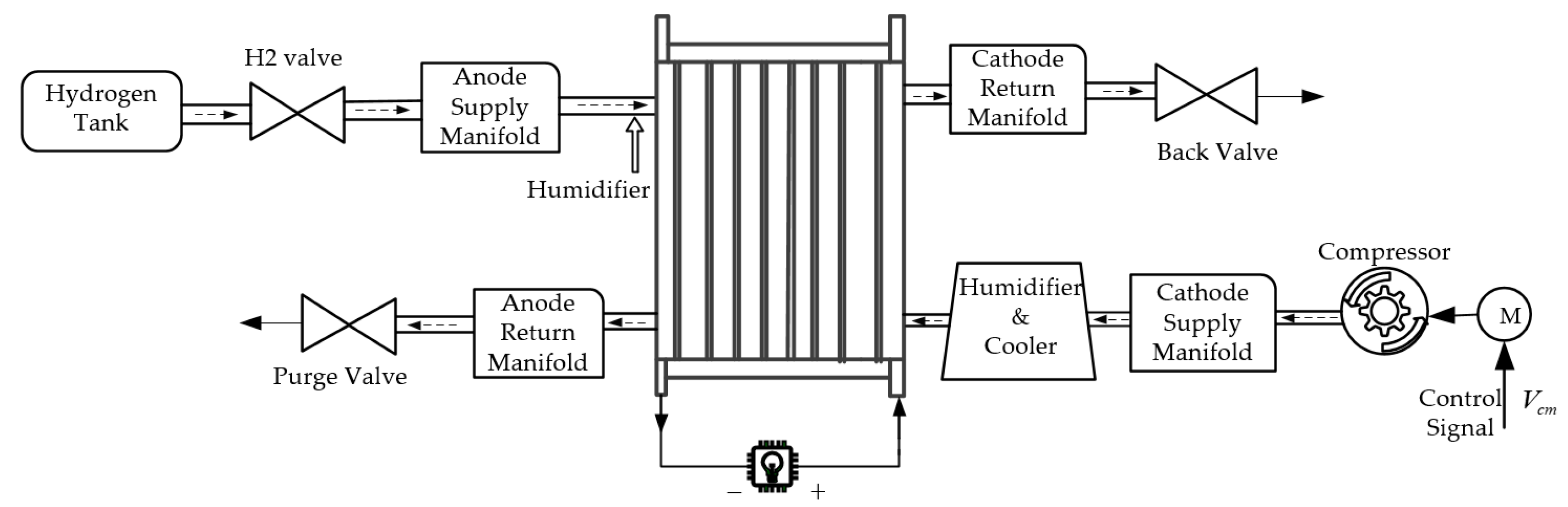
Figure 2.
Actual and estimated values of cathode pressure under load changes.
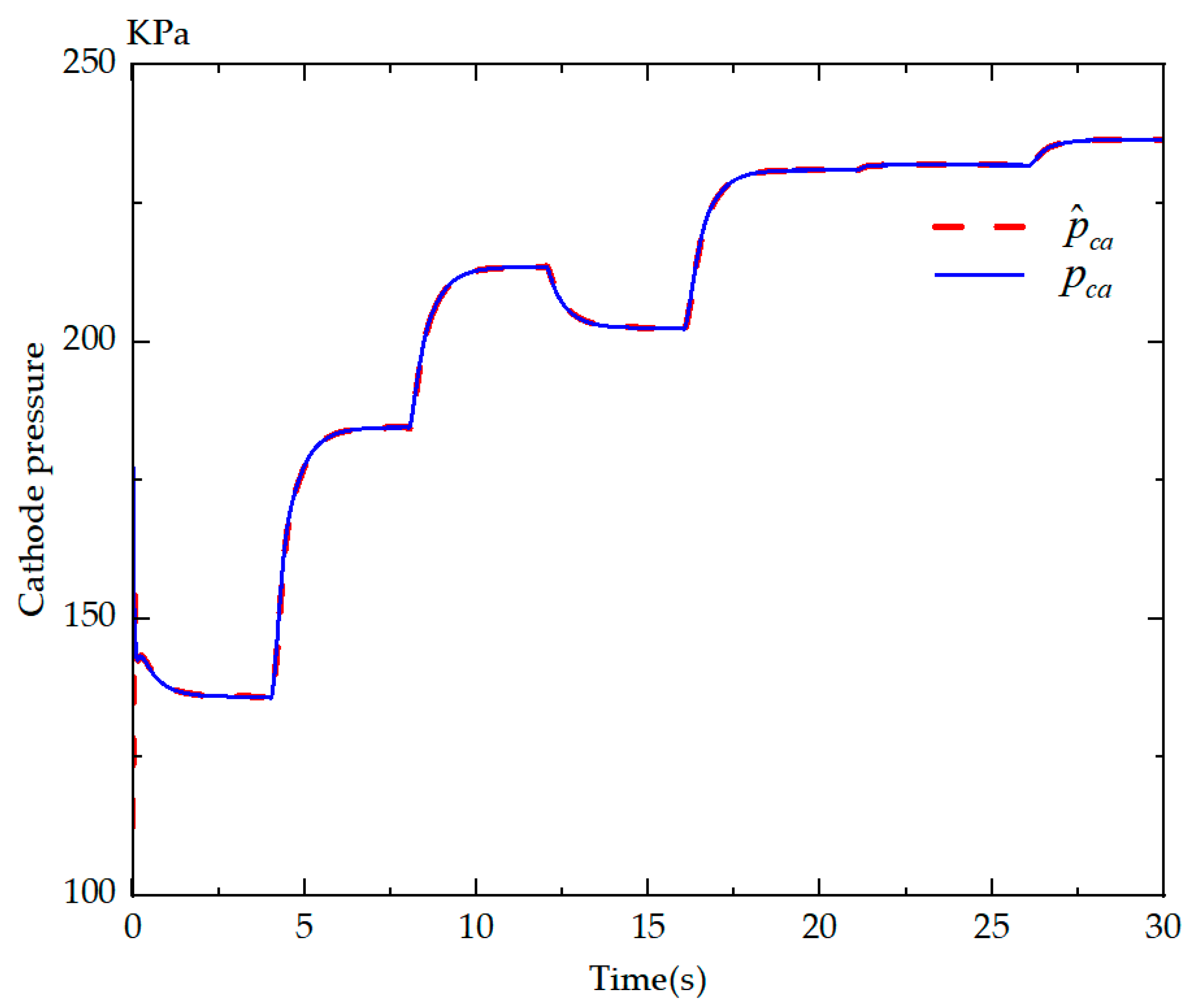
Figure 3.
Estimation error of ESO.
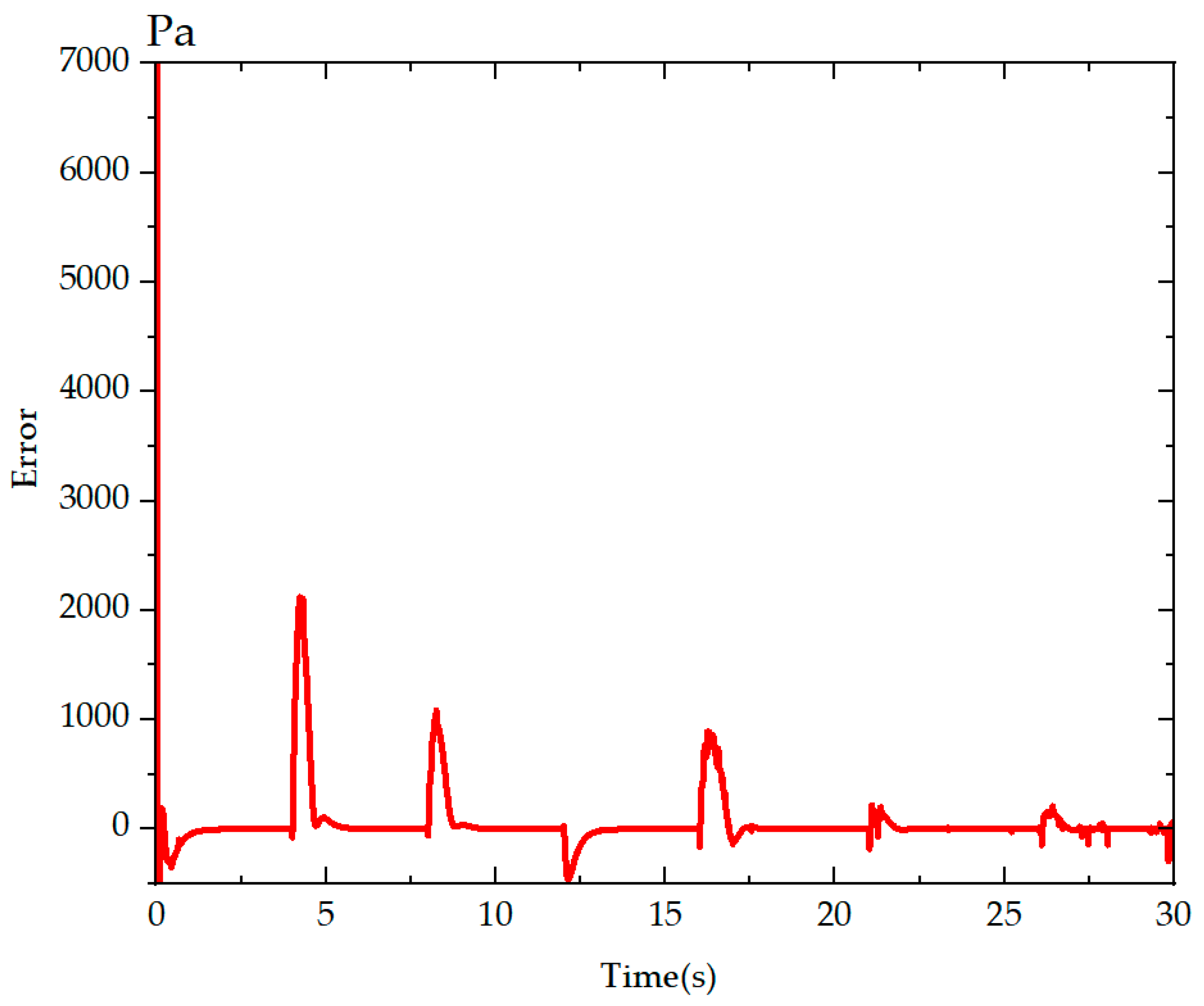
Figure 4.
Flow chart of the OER control method.
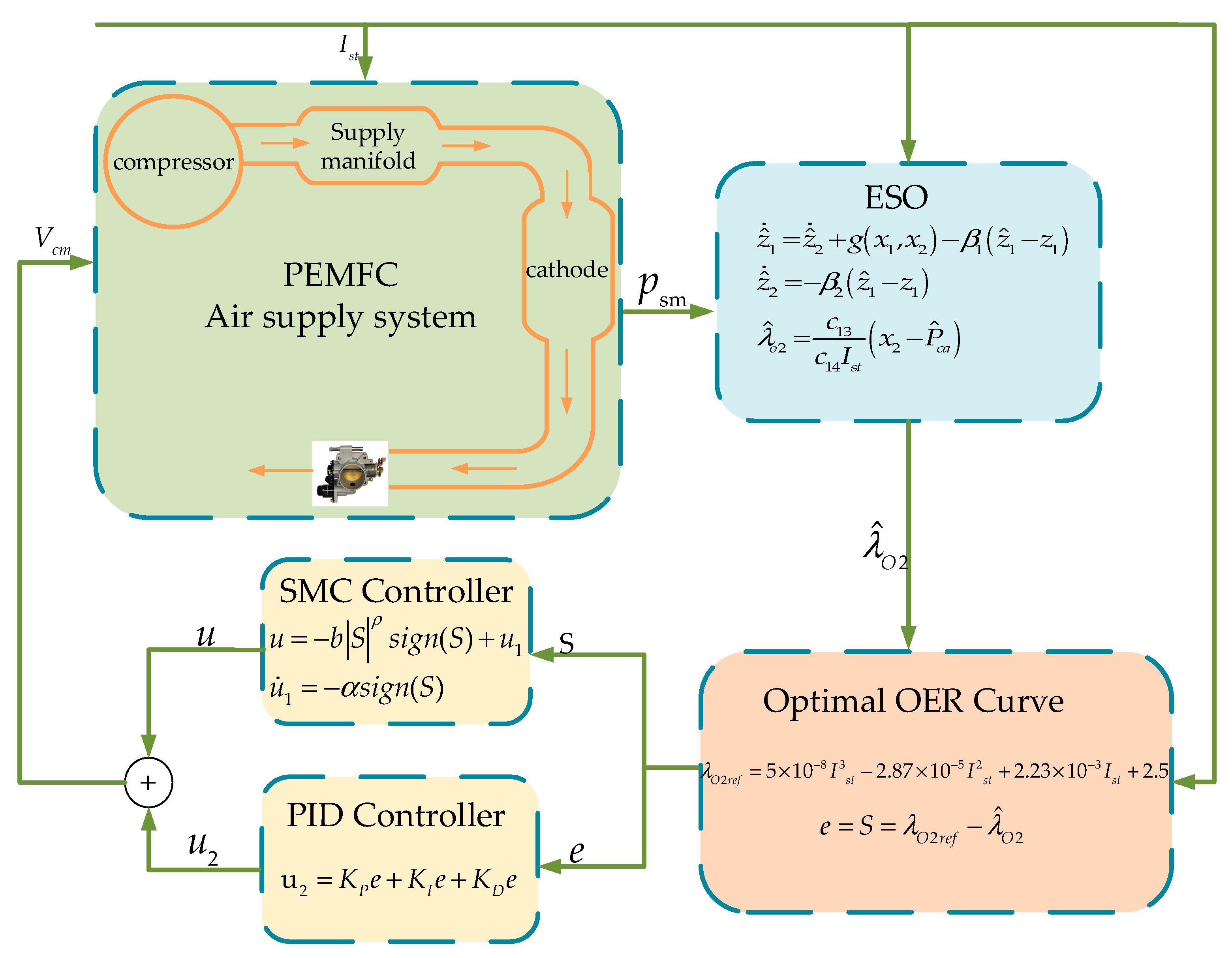
Figure 5.
SMC and PID cascade control algorithm block diagram.

Figure 6.
The load of PEMFC.
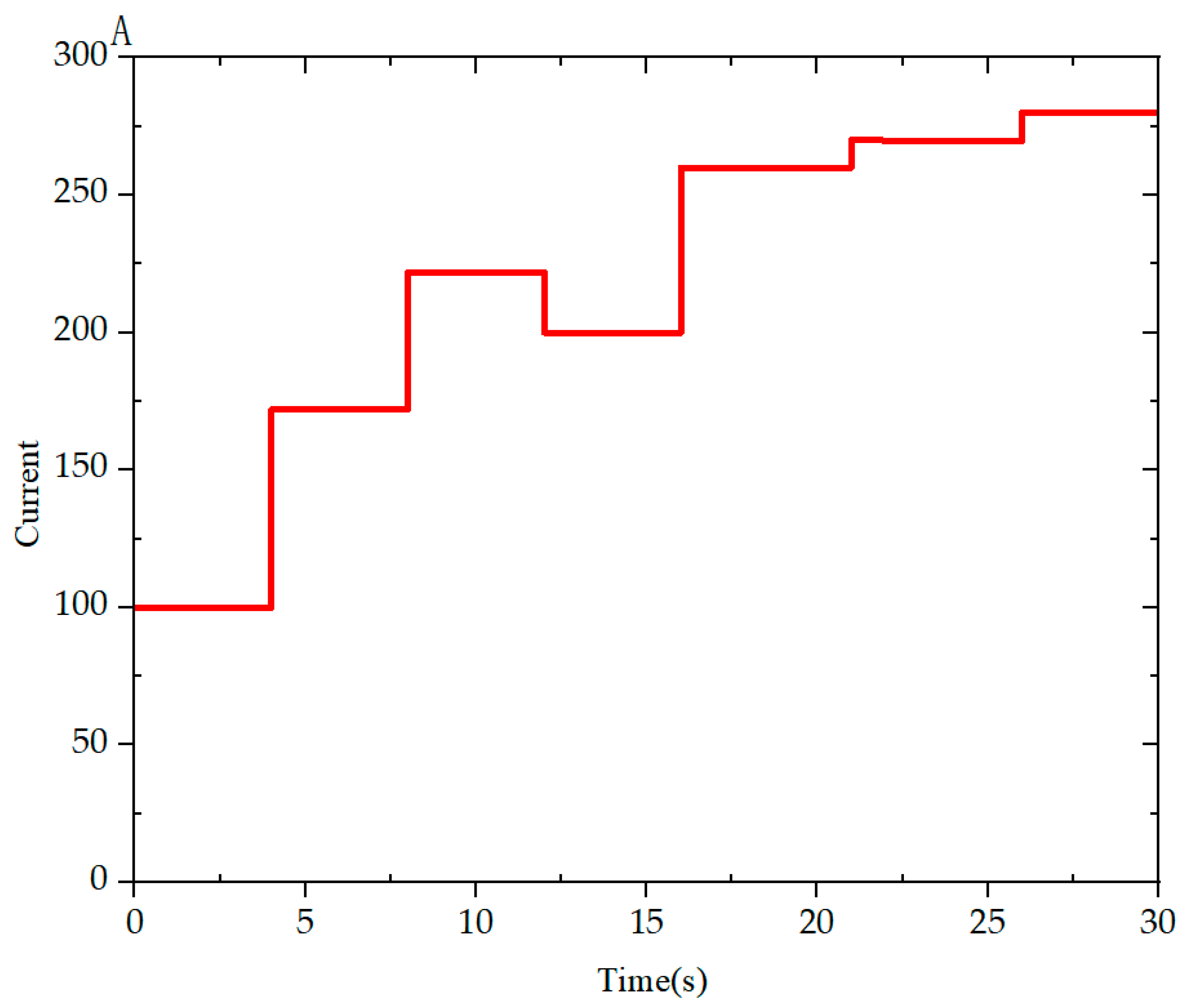
Figure 7.
(a) OER results of PID and SMC controller cascade control and PID control under various loads are compared in simulation. (b–d) are local magnifications of simulation OER.
Figure 7.
(a) OER results of PID and SMC controller cascade control and PID control under various loads are compared in simulation. (b–d) are local magnifications of simulation OER.
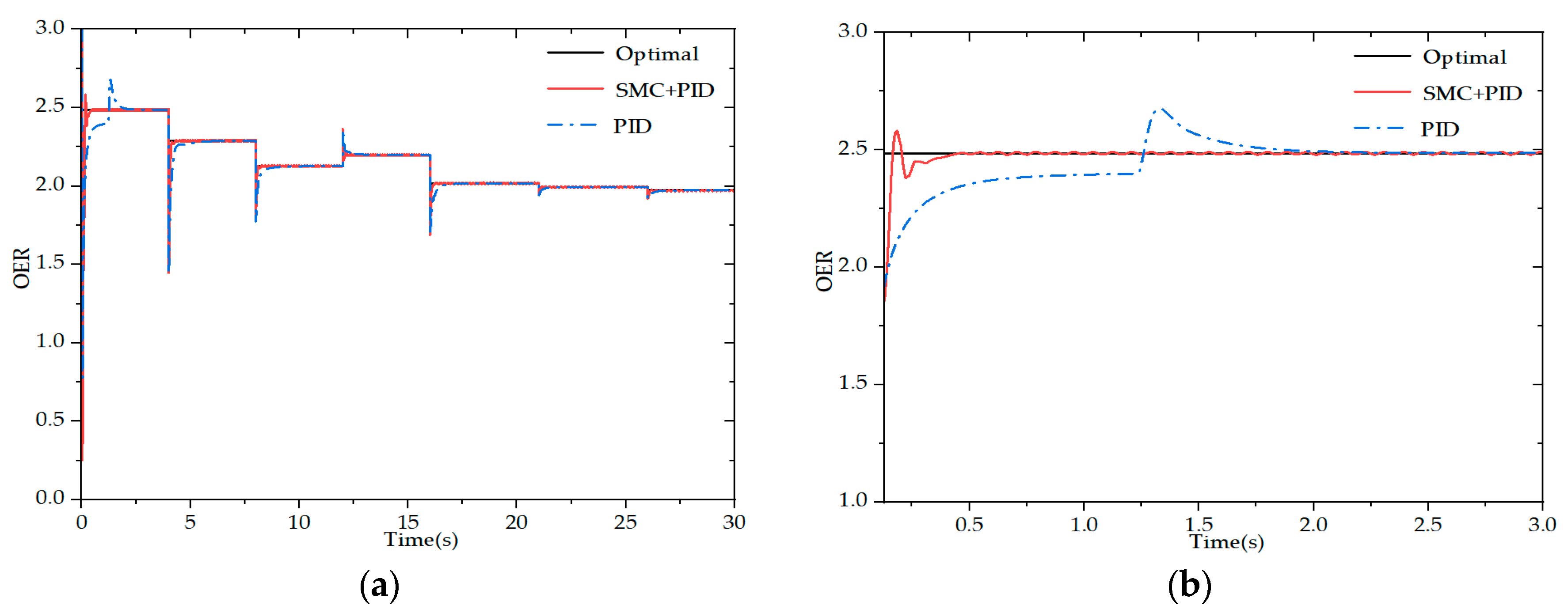

Figure 8.
(a) OER results of PID and SMC controller cascade control and Fuzzy adaptive PID control under various loads are compared in simulation. (b–d) are local magnifications of simulation OER.
Figure 8.
(a) OER results of PID and SMC controller cascade control and Fuzzy adaptive PID control under various loads are compared in simulation. (b–d) are local magnifications of simulation OER.

Disclaimer/Publisher’s Note: The statements, opinions and data contained in all publications are solely those of the individual author(s) and contributor(s) and not of MDPI and/or the editor(s). MDPI and/or the editor(s) disclaim responsibility for any injury to people or property resulting from any ideas, methods, instructions or products referred to in the content. |
© 2022 by the authors. Licensee MDPI, Basel, Switzerland. This article is an open access article distributed under the terms and conditions of the Creative Commons Attribution (CC BY) license (https://creativecommons.org/licenses/by/4.0/).
Share and Cite
MDPI and ACS Style
Tang, A.; Yang, L.; Zeng, T.; Yu, Q. Cascade Control Method of Sliding Mode and PID for PEMFC Air Supply System. Energies 2023, 16, 228. https://doi.org/10.3390/en16010228
AMA Style
Tang A, Yang L, Zeng T, Yu Q. Cascade Control Method of Sliding Mode and PID for PEMFC Air Supply System. Energies. 2023; 16(1):228. https://doi.org/10.3390/en16010228
Chicago/Turabian StyleTang, Aihua, Lin Yang, Tao Zeng, and Quanqing Yu. 2023. "Cascade Control Method of Sliding Mode and PID for PEMFC Air Supply System" Energies 16, no. 1: 228. https://doi.org/10.3390/en16010228
Note that from the first issue of 2016, this journal uses article numbers instead of page numbers. See further details here.