
Recent Advances in the Study of In Situ Combustion for Enhanced Oil Recovery
by
 ,
,
Andrey V. Minakov
1,2,*, 
Victoria D. Meshkova
1,*,
Dmitry Viktorovich Guzey
1 and
Maksim I. Pryazhnikov
1 1
Department of Thermophysics, Siberian Federal University, 660041 Krasnoyarsk, Russia
2
Kutateladze Institute of Thermophysics SB RAS, 630090 Novosibirsk, Russia
*
Authors to whom correspondence should be addressed.
Energies 2023, 16(11), 4266; https://doi.org/10.3390/en16114266
Submission received: 15 March 2023
/
Revised: 12 May 2023
/
Accepted: 16 May 2023
/
Published: 23 May 2023
(This article belongs to the Special Issue Enhanced Oil Recovery Processes Evaluation, Design and Implementation)
Abstract
:Global estimates for our remaining capacity to exploit developed oil fields indicate that the currently recoverable oil (light oil) will last for approximately 50 years. This necessitates the development of viscous and superviscous oil fields, which will further compensate for the loss of easily produced oil. In situ combustion is the most promising production method, which allows for increased oil recovery from a reservoir. This being the case, this study provides an overview of global trends regarding the research and implementation of the method under consideration, in order to promote understanding of its applicability and effectiveness. The background to the development of the method is discussed in detail, illustrating the growing interest of researchers in its study. Cases of both successful as well as inefficient implementations of this method in real oil fields are considered. The main focus of the article is to investigate the influence of the parent rock and catalysts on the combustion process, as this is a new and actively developing area in the study of enhanced oil recovery using in situ combustion. Geological surveys, in addition to experimental and numerical studies, are considered to be the main methods that are used to investigate processes during in situ combustion. The analysis that we carried out led us to understand that the processes which occur during the combustion of heavy oil are practically unpredictable and, therefore, poorly understood. The specificity of the oil composition under consideration depends on the field, which can lead to a change in the required temperature regimes for its production. This indicates that there exists multiple specific applications for the method under consideration, each requiring additional full studies into both the fractional composition of oil and its reservoirs. The article also considers various technologies for implementing the in situ combustion method, such as ND-ISC, THAITM, COSH, CAGD, and SAGD. However, the literature review has shown that none of the technologies presented is widely used, due to the lack of an evidence base for their successful application in the field. Moreover, it should be noted that this method has no limits associated with the oil occurrence depth. This technology can be implemented in thin reservoirs, as well as in flooded, clayey, sandy, and carbonate reservoirs. The review we have presented can be considered as a guide for further research into the development of global solutions for using the proposed method.
1. Introduction
It is impossible to imagine modern society without using oil, the most widely used natural resource. One of the definitive properties of oil is that it is a powerful source of energy. However, the more advanced our civilization becomes, the more energy is required for further progress. At the same time, the development of oil refining technologies has allowed us to move away from the classic use of hydrocarbons as raw materials. The components, obtained from oil refining, can be used as the primary and basic materials to produce various items that are used in everyday life. This is one of the reasons why more than 16% of the extracted hydrocarbons are channeled into such industries each year. Based on these estimates, the leading international analytical centers have concluded that, in the future, our global economy will not be able to exist without oil. While there is a problem of increasing “easily accessible” oil production, such production is becoming insufficient to meet the demand of society. The fact is that in the past 20–30 years there has been a steady tendency to reduce carbon stocks, which aggravates the situation.
According to PRMS (Petroleum Resource Management System) classifications, there are now such concepts as proven reserves and recoverable resources. The emergence of these terms is due to the fact that the definitions of “reserves” and “resources” in different countries have different interpretations and different meanings. Most of the extracted hydrocarbons belong to the concept of “proven reserves”, which means that they are extractable at the current level of technological development, and that their extraction can be economically viable and environmentally safe. In general, such reserves belong to the industrial categories A + B + C1. Category A includes developed reserves. Category B includes reserves which have been developed and explored, though not drilled (B1), as well as those which are developed and undrilled, but rather estimated (B2). Category C1 likewise only includes proven oil reserves [1]. According to the reports, “proven reserves” of the producing oil fields will last for years, at most [2].
In this regard, “recoverable resources”, such as the prospective and forecasted resources of categories C2, C3, D1 (promising oil resources), and D2 (projected oil resources), are of particular interest. Their extraction is associated with several difficulties, one of which is insufficient knowledge of the geological evidence for them. Recoverable resources may include both conventional reserves, which can be effectively developed using existing technologies, and nonconventional reserves (oil sands, extra-heavy oil (EHO), oil shales, etc.), which require different technological solutions and modern approaches, and may differ from conventional technologies. It should be noted that, although production technologies are available for some categories of unconventional reserves, they have a number of drawbacks due to this poor level of understanding [3].
It Is the extra-heavy oil which makes up the world’s major unconventional reserves. According to exploration data, the largest viscous and high-viscosity oil reserves are concentrated in Canada, Venezuela, Russia, the United States of America, and China. Considerable interest in the efficient extraction of these raw materials is limited by some of the difficulties associated with the operational costs of extraction [4].
There are several definitions of heavy crude oil and bituminous sands, and of the type of hydrocarbons they belong to. According to the UN Information Center, this class includes every natural hydrocarbon with viscosities above 10,000 mPas, which includes oil-shale kerogen, natural bitumoids (rock oil), crude oil, natural gas, and condensate. The US Geological Survey gives a more detailed definition: heavy oil is characterized by asphalt-base oil with high density (low API gravity) and high viscosity; it contains asphaltenes, consisting of very large molecules, including sulfur, and up to 90% of heavy metals in its chemical structure. Another definition of heavy oil is used by National Petroleum. Nevertheless, there are various definitions for heavy oil; the upper limit for it is set at 22° API, and a viscosity of 100 cP. At that level, EHO is usually a portion of heavy oil with 14–10° API (972–1000 kg/m3), and rock oil has less than 10° API (1000 kg/m3) [5,6,7].
There are several theories regarding the origin of heavy oil and rock oil (native bitumen), one of which states that oil can be recovered from the source rock as immature oil that includes a low rate of heavy oil. It is also hypothesizes that mostly high-viscosity oil is recovered from the source rock as light and middle oil, followed by a shift into a natural reservoir (trap). Due to structural dislocations, stratigraphic and lithological screening for oxidation conditions formed in the trap can turn light oil into heavy oil through various processes, such as water flushing, bacterial degradation, and evaporation. In this case, biodegradation has an aerobic nature. As a third approach, biodegradation is considered at a depth of 1.5–6 km and at a low temperature of 70–80 °C in underground reservoirs. Heavy oil is considered to be those remnants of light oil that have lost its original properties, and are located at the end of geological basins [8,9].
Compared with the extraction of light oil, heavy oil has specific properties and requires other methods of oil reservoir development that differ technologically and economically. Using a particular technology depends on several conditions, such as the geological structure and formation conditions, the physical and chemical properties of the reservoir fluid, as well as the state and level of reserves of raw hydrocarbon deposits. There are three groups of mining methods depending on scope of their application: open-pit and mine development; cold mining; and thermal mining [10].
Among the presented groups, it is the thermal mining method that does not have strict restrictions on the maximum levels of oil viscosity, and therefore is the most promising for research and implementation.
Among the thermal mining methods of increasing oil recovery, in situ combustion holds a specific status. In this regard, this study provides a comprehensive analysis of global trends in the research and application of the above noted method for the extraction of hard-to-recover hydrocarbon reserves.
2. Prior History of the In Situ Combustion Method
The extraction of viscous and superviscous oil using in situ combustion is the most promising approach because it allows for an increased level of oil recovery in severe geological and physical conditions. This method is based on the fact that the heat for the oil bed is generated inside it through the combustion of the fuel and flue gases formed during the combustion process [11,12]. Having such a significant advantage, the in situ combustion method ranks second among other methods [13].
In 1932, A.B. Sheinman [14,15], the main proponent of thermal technologies in the development of oil fields, was the first to propose in situ coal gasification method. In 1934, he tested this method at the Sharkan underground oil field (Kuban, Russia) [16]. In addition, the in situ combustion method had been actively developed and implemented in US oil fields as early as in 1916. The first practices were patented in the United States in 1923, and in 1948, ten field experiments were carried out in different parts of the United States, Canada, and South America, including the Colorado oil shale [17]. About 230 pilot projects of in situ combustion were fulfilled in the US from 1950 to the end of the 20th century, of which 37 of them were technically and economically successful; however, more than 130 projects failed [18].
In 1991, the Oil and Natural Gas Corporation (ONGC), the largest Indian oil company, had successfully implemented the in situ combustion method as a pilot project at the Balol oil field, and by 1997 it had already been launched industrially at both the Balol and the Santal oil fields. It breathed new life into these oil fields, and increased the oil recovery index from 6–12 to 39–45% [19]. Starting from 1963, both pilot and semicommercial tests were carried out at the Suplacu de Barcau oil field in Romania. At the initial extraction, the recovery index was 9.2%, while by the final extraction it had increased to 50%. This method was then used at the Balaria (1975), East Videle (1979), and West Videle (1980) oil fields, where the recovery index was at least 35% [20]. Since 1957, various methods of thermal mining effects have been tested in the Venezuelan oil fields located on the eastern coast of Lake Maracaibo (specifically, the Bolivar coastal oil fields near Tia Juana, Lagunillas, and Bachaquero), and the in situ combustion method proved to be the most successful [21].
However, since the 1970s, with the large number of failed projects, the interest to this technology has been reduced, as well as the number of tested oil reservoirs. As a result, just eight such projects were launched in the United States in 1997–1998, and about 20 projects in other countries and different oil producing areas (Canada, Albania, Azerbaijan, China, Hungary, Romania, Russia, India, Kazakhstan, etc.) [15,17,18,19,20,21,22,23].
In the 20th and 21st centuries, the in situ combustion method has undergone many fundamental changes, having been implemented in many oil fields and modified to suit the characteristics of the feedstock. Thus, in 2012, 11 heavy-oil-extraction projects were implemented in the United States, and most of them were successful [24]. In Canada, this method ranks second in commercial technology, whose implementation allows the production of about 23 million tons of rock oil. It is these Canadian experiences in the development of heavy oil and rock oil fields that show us that the successful organization of large-scale production is possible only after reasoned conclusions, based on scientific and laboratory studies [16,25]. China faces a number of production problems, because most of the heavy oil reservoirs have already passed the middle or the last stage of steam stimulation, and their throughput capacity has significantly diminished. Steam stimulation and water-flooding methods in oil recovery were tested at the oil fields of the Shengli, Liaohe, and Xinjiang regions, but unfortunately their implementation had no effect. The in situ combustion method is reported to have gained some advantages over other methods in multiple studies and has thus begun to be actively used in heavy oil production in China [20,22,26,27].
The historical survey we conducted clearly showed that the production of viscous and superviscous oil using the in situ combustion method is associated with a certain problem. First of all, this is due to the fact that, until now, light oil reserves were plentiful and production technologies had been developed and successfully applied, and therefore there was no need to study the production of viscous and extraviscous oil. On the other hand, geotechnical and geodesic surveys were not sufficient to determine the geological and physical characteristics of the oil bed for the subsequent implementation of the in situ combustion method. Lastly, in situ combustion processes are poorly predictive and difficult to study (Figure 1). These circumstances underline the need for further research to improve the method.
3. Scientometric Analysis of Research Activities
Using the Web of Science (WOS) and Scopus bibliographic databases for the last five years, the scientific research on the in situ combustion method was analyzed to understand the efficiency of scientific contributions.
We have used the term ‘in situ combustion’ to explore a broader range of scientific research. About 554 research works were found, published within a timeframe from 2015 to now. Most of them were reviews and papers presented at scientific conferences (Figure 2).
Figure 3 and Figure 4 show the leading research universities and organizations that have made the most considerable contributions to the study of this method. Southwest Petroleum University of China, Kazan (Volga Region) Federal University, and the National China Petroleum Corporation are at the top of this list (Figure 4).
The analysis of the research area shows that the main purpose of research is to gain new knowledge in the field of energy (34%). It also shows that the in situ combustion method is necessary for oil extraction, which is the paramount for developing world energy. Receiving actual data on the geological study of heavy and extra-heavy oil field locations and into the effects of parent rock on the in situ combustion processes (as well as the basic characteristics of crude hydrocarbons) would allow us to identify the possibilities of using this method most effectively. Based on this fact, the sciences related to geology, planets, and the environment, are still in a challenging scientific search (Figure 5).
4. The Main Processes of the In Situ Combustion Method
The basic principle of the in situ combustion method is that when using a bottom-hole zone or injection well, the conditions necessary for initiating and forming a stable combustion front are created. At the same time, an oxidizer, which allows for the maintenance of a stable combustion process, is injected through the injection well into the reservoir [27,28]. Depending on the movement of the combustion front and the air flow, the process can proceed both in the forward and a reverse direction.
The forward combustion is the commonly used one; the combustion front is initiated by igniting the oil in the reservoir near the bottom-hole of one of the injection wells. After this, air (which supports movement of the combustion zone through the reservoir) is pumped into the reservoir. When the front moves towards the air flow, reverse combustion occurs, which is fraught with some difficulties; in fact, it leads to increasing operating costs because maintaining the stable combustion process requires more oxygen-containing gas than is needed during the forward combustion. However, the main drawback is that heavy fractions (i.e., cokes) are formed during this process. They begin to burn and, as a result, the process returns to a forward combustion characterized by an overheating, which greatly reduces the oil recovery of the reservoir [25,29]. However, the reverse combustion may have some advantages over the forward combustion for heavy oil reservoirs with lower permeability, or may be used as a method of preheating the reservoir [30].
During the numerous tests, it was found that in situ combustion can be made more efficient by supplying water with the oxidizer, which affects the temperature distribution in the reservoir and changes the intensity of chemical reactions. These changes are caused by the fact that the greater the amount of water, the more significantly does the velocity of the heat wave in the convective front increase. That is, the more water is supplied, the higher the wave velocity, which becomes equal to the combustion front propagation rate, i.e., the heat wave inversion occurs [31,32,33,34]. As noted in the study by Jacques et al. [35], three basic types of the processes (corresponding to increasing the water–air ratio) can be distinguished: normal wet combustion, incomplete wet combustion, and superwet combustion, as shown in the diagram below, along with the main temperature parameters of these types (Figure 6).
It should be noted that to describe the ignition process, critical saturation during on-site combustion was studied, which depends on the maximum saturation with water at which ignition is possible. Therefore, a saturation above or below this criterion indicates the possibility of ignition. The comparison of critical ignition with actual reservoir water saturation can be used to understand the possibility of in situ combustion at a given oilfield [36,37].
The main point is that successful ignition depends directly on the content of a light oil fraction with the lowest activation energy. Under some conditions, this fraction can be saturated, while under other conditions it can be in the form of aromatic compounds. To understand whether there is enough energy to initiate an effective combustion process, it is necessary to accurately determine the characteristics of this fraction. The chemical reactivity and thermodynamics of partial-fraction-oxidation products with the lowest activation energy are the secondary factors determining the quality of ignition. The enrichment of the injected air with oxygen greatly affects the combustion process, while the injection of hot air has little or no effect. The reservoir pressure and temperature are also not important parameters [26,38].
The initial ignition can be either spontaneous or artificial, by supplying extra heat with gas-burners and bottom-hole electric heaters, or by introducing chemical substances into the bottom-hole zone in the form of oxidizers, etc. [39,40]. Table 1 presents the advantages and disadvantages, as well as the limitations, of implementing a specific initiation of artificial ignition [41]. It should be noted that the determining criteria for choosing an artificial ignition method depends on the nature of the oil-field, as well as the necessary logistical support available.
In general, the extraction of viscous and superviscous oil using the in situ combustion method depends on the interaction between the hydrocarbons in the oil reservoir and oxygen in the air, which produces a large amount of heat. This heat accumulates in the vicinity of the moving combustion front. At the same time, the combustion is sustained by a part of the oil in the reservoir, which accumulates due to its displacement by combustion gases, water vapor, vaporized oil fractions in front of the combustion front, and changes because of distillation, cracking, and other complex chemical processes [42,43,44,45,46,47]. Some processes are characterized by their complex nature, which makes obtaining relevant scientific knowledge quite challenging.
5. Basic In Situ Combustion Technologies
There are several technologies for implementing the in situ combustion method, which differ from each other structurally and by their main approaches to forming the combustion front area. A diagram of the main existing technologies is shown in Figure 7.
TD-ISC (top-down in situ combustion) involves the stable propagation of a high temperature combustion front from the top to the bottom of the well, where heavy oil is accumulated. The combustion process is initialized and maintained with the injection of an oxygen-containing gas at the top of the reservoir, with mobilized oil draining to a lower horizontal producer well. Most of the injected oxygen is consumed in high temperature combustion reactions at the combustion front. Oxygen that passes unreacted through the front, reacts in lower temperature reactions to produce a layer of coke which is subsequently burned as the combustion front moves through. Hot combustion gases and thermally cracked light ends mix with the oil ahead of the high temperature front, heating, upgrading, and driving the oil using a top-down gas drive.
As the top-down process holds great promise, existing potential problems must be solved before it can be considered for application in field conditions. The main problem is that it is necessary to overcome high viscosity in the primary layers of heavy oil. It is necessary to evaluate the methods of obtaining injectivity, as well as the ability to successfully apply this process to reservoirs that have already been partially depleted by a previous recovery operation. Both the stable advancement of the combustion front through the reservoir and the efficient drainage of the mobilized oil into the producing wells need to be proven.
Latterly, Petrobank Energy and Resources Ltd. have patented the THAI technology, which facilitate the formation of an inclined (horizontal) combustion front using a complex system of well arrangement. Injection wells must be positioned so that the combustion front advances from top downward to the producing well, due to gravitational and capillary forces required to stabilize it [42,43]. This technology was implemented in the context of the Whitesands project. According to the data, the oil recovery factor was 70–80%, but in fact it was much less, amounting to about 55%. The laboratory studies have shown that THAI increases the oil API by 10°, and during the combustion process the quality of the extracted oil gets partially better. It should be noted that there are some limits for the reservoir depth (which should be at least 100 m and no more than 500 m), and the thickness of the reservoir should vary from 12 to 45 m [44,45].
In the above discussed processes, the main problem of the early breakthrough of oxygen has remained unsolved. Finding a solution to this problem served an impetus for developing and implementing the COSH (Combustion Override Split-production Horizontal-well) process. The main idea was again to combine well locations, but in this case, it was proposed in order to divert gas flows from the collector using side wells, using the horizontal well as a production well. The horizontal production well performs the same function as it does in THAI, providing a large contact area between the formation and the flame front. Gravity drainage stabilized the development of the combustion front along the producer well. The oxygen gas was then injected through vertical injection wells; this can be air, oxygen, or recycled oxygen gas. As a rule, the gas is injected into the top of the producer reservoir. Maintaining continuous gas injection into the reservoir and cold-water circulation in the wells will prevent damage from combustion. The wells can also be used to determine the chemical composition of the soil, and accurately determine the location of the productive zone before drilling a horizontal producer well; it can also be used to control the temperature profiles at the bottom part of the gas chamber using cemented thermocouples. Before using the horizontal injection well, it should be protected from combustion damage that may arise due to differences in injection capacity along the well [46].
The comparison between COSH and classic in situ combustion shows that it is the distance between the combustion front and the producer well being smaller that provides a higher heat transfer efficiency. The COSH process leads to the gravity separation of gas and water that blocks combustion. However, synchronous production (of gas and liquid) reduces the production problems, thus providing better conditions. Similar studies have been carried out in the United States on West Hackberry, where the COSH process was also tested.
Despite attempts to improve the technological process of in situ combustion, none of the processes under consideration provide a comprehensive satisfactory solution. Issues related to the emergence of obvious problems still remain open. Certain difficulties are associated with the correct choice of the oil location, which leads to instability of the combustion front. The main operational difficulties associated with gravity segregation and the emergence of air channels remain unresolved; likewise, approaches to regulating the ratio of air supply to the amount of oil produced have not yet been worked out.
The use of gravity drainage is considered an alternative to the classical approach. CAGD (Combustion Assisted Gravity Drainage) improves the traditional approach by using a horizontal injector at the top of the reservoir in conjunction with a horizontal extraction device located at the bottom. Due to the horizontal position of the injector, the combustion front moves towards the rear end of the injector and expands laterally after the start of combustion along the injector. Then, the heated oil flows down, being directed to the underlying horizontal production well with the effect of gravity drainage. One of the important features of this method is that properly oriented double horizontal wells promote the propagation of the combustion zone and stabilize the combustion front growth.
Numerical studies aimed at evaluating the performance of the CAGD process compared to THAI technology show that, when using gravity drainage, a lower ratio of total energy input to oil output is observed; this reduces operating costs, but at the same time significantly increases oil recovery.
Recently, special attention has been paid to the technology of the thermogravitational drainage of oil reservoirs, a process called Steam Assisted Gravity Drainage (SAGD), which is also used in fields with very viscous oil, helping to “warm up” the reservoir and cause the oil to come out faster. Depending on the relative position of the injection and production wells, SAGD can be one of two types: ‘classic’ and counter SAGD. In the classic method, both wells are drilled from the same well pad, and the injection well is located approximately 5 m higher than the production well. Steam is then supplied to the injection well under pressure, and the heated oil with light fractions under the effect of gravity descends into the horizon of the production wellbore. A schematic diagram of the implementation of SAGD technology is shown in Figure 8 [48,49].
Counter SAGD involves drilling out blocks from two well pads, which are separated from each other by an average of 1 km depending on the location of the horizontal sections of the wells. Production wells are drilled from one point, followed by steam injection wells, so that the horizontal ends of the steam injection wells are located above the horizontal ends of the production wells. SAGD requires huge amounts of steam (hundreds of tons per hour) to be injected into the reservoir. At the same time, the optimum temperature sufficient to heat the oil must be observed inside the steam well (Figure 8).
In recent years, several SAGD modifications have been developed, such as Vapor Extraction (VAPEX), Expanding Solvent SAGD (ES-SAGD), Solvent Aided Process (SAP), and Steam Alternating Solvent (SAS). The need for SAGD modifications is due to the desire to improve the economic performance of projects, as well as to take into account the specific geological and geophysical conditions of the field, and meet stringent environmental protection requirements. SAGD projects are the largest consumers of fresh water in the oil production regions, and payments for greenhouse gas emissions of steam production could become a significant cost in the foreseeable future.
The widespread implementation of these technologies is limited by the insufficiency of the evidence base for their successful application in the fields. A small number of test works cannot provide enough information and knowledge to allow an assessment of the overall effectiveness of each particular technology.
6. Recent Advances in the Study of In Situ Combustion Methods
As noted above, extensive descriptions of reaction zones and the main processes involved are available in the literature [27,29,34]. However, this information is not sufficient since it lacks enough data on the effect of the heterogeneous natural structure of the deposit, because it is the latter that can significantly or even radically change the development course of processes, as well as lead to an unpredictable scenario [31,32,33,34]. It should be noted that the initial ignition strongly depends on the properties of crude oil, and, accordingly, each oilfield will have its own low-temperature and high-temperature oxidation (oil cracking) zones, not to mention the required amount of supplied air that will be needed to maintain effective combustion [50,51,52].
To define the range of key parameter values and eliminate errors, it is necessary to conduct a series of numerical and experimental studies before launching the projects. Particular attention should be paid to the experimental part since the primary data that will allow for understanding the specifics of both the deposit and the initial raw hydrocarbon are produced in the course of laboratory studies. This will facilitate the evaluation of the possibility for an effective practical application of the in situ combustion method in the field. Ultimately, the knowledge gained can be backed up using numerical simulation, and only then will one be able to proceed to the development of a field for producing viscous and ultraviscous oil, considering all the individual characteristics of both the very method and the heterogeneous structure of the formation. Based on the above, a typical diagram illustrating the research involved in designing in situ combustion is shown in Figure 9, comprising the following main blocks: geological surveys, experimental laboratory research, and numerical simulation.
6.1. Review of Experimental Approaches into the Study of the In Situ Combustion Method
The fundamental research areas are considered to be the experimental work on kinetic cells through ramped temperature oxidation (RTO), as well as into combustion pipes designed to study the one-dimensional method of in situ combustion. These approaches allow for the determination of the amount of fuel needed for cracking, as well as estimating the velocity of the combustion front movement [53,54,55].
As a rule, experimental installations have the same type of structural design. They usually consist of five main elements, namely, the gas injection system, combustion pipe/chamber, a liquid extraction system, a gas chromatograph, and a measurement system for moist tests, as well as a data recording system [56].
The combustion pipe is a horizontally arranged pipe into which air is blown from one side and liquid is supplied from the other side. The temperature along the pipe is constantly monitored using thermocouples, which are located along the entire length of the pipe. Initially, the supplied gas is heated using electric heaters, and when the temperature at the first control point reaches 290–310 °C, air is supplied at a rate of 2.5–3.5 L/min to initiate the combustion process. As a rule, in order to ensure successful ignition at a measured temperature of 400 °C, additional heating is turned on using an electric heater. Peak temperature values are recorded with thermocouples, which indicate the location of the combustion front. The analysis of exhaust gases is carried out using a gas analyzer [57,58]. A typical schematic diagram of the combustion chamber is shown in Figure 10.
Processing of the data obtained allowed the determination of the average temperature of the combustion front, while the ratio between the carbon and hydrogen atoms (H/C) allows the indication of the predominance of either the LTO (Low temperature oxidation) or the HTO (high temperature oxidation) reactions. As a rule, the value H/C ≥ 3.8 indicates the predominance of LTO, whereas H/C ranging from 1.0 to 2.1 indicates the predominance of HTO reactions.
Research relating to the study of crude oil combustion in a porous medium, with an air flow using a porous medium thermo-effect cell (PMTEC), is of particular interest [59]. The uniqueness of this development lies in the ability to quickly determine the characteristics of crude oil, since it is exactly these parameters which are crucial for implementing the methods aimed at increasing oil recovery by means of air injection. An illustrative diagram of this process is shown in Figure 11.
The combustion of seven types of crude oil, including two types of light, medium, and heavy oil, as well as one type of extraheavy oil, was investigated using PMTEC. Low-temperature combustion (LTC) occurs already at temperatures of about 270–280 °C with a further increase in temperature to 700 °C, accompanied by the release of CO2 and CO for medium, heavy, and extra-heavy oils, with the exception of two light oils. The occurrence of LTC depends on the properties of crude oil. Besides, this process can propagate in a porous medium with an air flow controlled using a fiber-optic system. It is this point that deserves further study since the occurrence of LTC and the propagation of its front can play an important role in the displacement of oil during the in situ combustion process.
A series of experiments on combustion in the pipe were carried out to study the characteristics of combustion process during the in situ combustion of heavy oil on the shelf [60]. Then, simulation studies were conducted to evaluate the efficiency of the combustion process in a typical offshore heavy oil reservoir.
The experimental setup consisted of a one-dimensional combustion pipe, an igniter, an injection system, a fluid analysis system, and a data collection system. The length and diameter of the combustion pipe were 72 and 7.5 cm, respectively. To register the temperature, 16 thermocouples were installed along the pipe (Figure 12).
The results showed that higher heating rates led to a shift in thermogravimetric curves towards an increase in the rate of weight loss. Oil production amounted to 547.78 m3/t, and oxygen input and the air/oil ratio in the combustion experiment were 95.1 and 97.27%, respectively. This study aimed provide technical support for the application of in situ combustion in offshore heavy oil reservoirs.
In [54], the researchers turned away from using the classical cylindrical combustion cell, and instead used the conical one, which allowed for the conduction of combustion studies at low air flow levels (Figure 13a). Particular attention should be paid to the design features; Figure 13b shows the radial arrangement of the thermocouple elements. ARi metal heaters with a power of 2 kW were mounted on the outer wall to prevent heat loss during operation. Figure 13 shows the radial arrangement of thermocouple elements; 2 kW metal heaters were installed on the outer wall to prevent damage during operation. The heaters were activated in 1D mode at a distance of 2.5 cm from the injection bottom, and the rest were mounted on a conical section at a distance of 14.0 and 40.6 cm from the injection bottom, respectively.
The results obtained from this revealed that after ignition, the combustion zone propagated evenly throughout the experimental cell; however, there was a certain change in the oxygen absorption kinetics as the combustion zone moved through the transition between the cylindrical and conical parts of the cell. It is supposed that such behavior is associated with the enrichment of the vapor phase with fuel in the near-wall area. Employing this type of chamber allows for the maintenance of the combustion process at an air flow of 3 m3/m2h, and operating pressure of 3550 kPa, which in turn leads to the successful oil displacement.
The main difficulties when conducting experimental studies are related to the lack of suitable scaling criteria when planning experiments [61,62]. In addition, conducting experiments is associated with large labor and financial costs. Based on the above, M.R. Islam and S.M. Farouq Ali were among the first to present in their work useful recommendations for developing such experiments, and also made a fairly complete description of the applicable laboratory methods used both previously and currently (Table 2) [63,64].
Analysis of laboratory work has shown that currently the majority of research is aimed at studying the effect of oil-bearing rocks on the in situ combustion processes, as well as identifying promising catalysts to improve the ignition and combustion processes.
To begin with, when scientists started investigated the origin of oil, they focused on the study of clay minerals, since they are the main constituent elements of oil-producing rock refuse that can generate and store oil. The presence of these minerals has an important influence on the properties of the deposit, namely, on its parameters, such as porosity and permeability [52,70]. In addition, clay minerals in oil-bearing rocks are very important, not only for assessing the quality of formation, but also for assessing the hydrocarbons’ displacement and movement, which is extremely important when oil is displaced in the reservoir [71].
It was logical to assume that the clay components of the rocks could well form the basis of a new series of catalysts to mitigate the conditions of the in situ combustion process. There are many theories stating that the clay content can increase the catalytic activity of the rock and, accordingly, intensify the in situ combustion process by reducing the LTO onset temperature, while significantly affecting HTO by lowering the temperature of this stage’s quality [72,73,74,75].
A team of scientists made a great contribution to the study of the effect of clay on various types of crude oil by conducting a series of experimental works with oil taken from the fields of Mexico and Alberta (Canada). Carrying out this study, it was revealed that reservoir rock consisting of a mixture of 3 wt% of clay and 97 wt% of the sand allows for the control of the combustion front propagation, which was not observed in the reservoir rock, which consisted only of sand. However, interaction of clay with crude oil at high temperatures results in its thermal decomposition, which, when visually analyzed, is manifested in the form of the lumps. This effect results from the level of saturated substances and asphaltenes in the feedstock [76].
Undoubtedly, the presence of clay greatly affects the in situ combustion performance, however it is difficult to speak to the unambiguity of this influence, since different samples of crude oil reacted differently. Some samples manifested quite a positive effect and led to an increase in oil production, while other samples showed the opposite effect.
Based on the above, it became clear that the catalytic effect of clay rocks depends not only on the composition of the initial crude oil, but also on the mineralogical composition of the very rocks. Thus, four types of clays, different in mineralogical composition, were considered in studies [59,77,78]. It was revealed that good catalytic activity was shown in clays containing quartz and mica. This effect is achieved due to the high levels of the second of these components, since mica leads to a decrease in the activation energy. The opposite effect was observed in clay rocks consisting of clinochlore and talc, as they demonstrated a strong inhibitory effect, starting from the later stage of LTO to the end of HTO stage. The combination of such trace elements greatly delays the isomerization and decomposition reactions, as well as the oxidative cracking reactions, which unexpectedly leads to forming a large amount of coke, which, in turn, significantly reduces the efficiency of the combustion process. The combination of minerals, such as kaolinite, montmorillonite, mica, clinochlore (as well as a mixed layer consisting of orthoclase and albite) also demonstrate a similar catalytic effect, as does a sample with a high mica content, but this effect is less pronounced, especially at the HTO stage.
The analysis of the literature allowed for the understanding that the presence of rocks or minerals really has both beneficial and negative effects on the crude oil oxidation. As already noted above, the majority of research has dealt with studying the effect of clay rocks, while studies aimed at studying the effect of carbonate minerals are quite scarce. This is due to the fact that clays are the main mineral of sandstone, and the carbonate rock differs greatly from it in its structure, mainly consisting of calcite and dolomite minerals, while including an insignificant number of impurities in the form of anhydrides, quartzites, and clay minerals. At the same time, the presence of calcite or dolomite has a significant effect on the combustion of crude oil [78]. In general, the presence of calcite or dolomite leads to easier ignition and a less intermittent combustion process. A good catalytic effect of the minerals in question is achieved by significantly reducing the activation energy; however, since for the maximum value for calcite is already reached at 175 kJ/mol, and for dolomite, at 225 kJ/mol, the catalytic effect of calcite is much stronger than that of dolomite. It follows from this that the level of these elements, especially calcite, leads to an increase in the combustion efficiency of crude oil in the in situ combustion process [59].
A low-soluble metal-based catalyst has been developed to improve the characteristics of in situ combustion by stabilizing the combustion front. Copper stearate is used to improve the oxidation of the heavy oil. Its catalytic effect in the presence and absence of additional elements, such as aluminum oxide or silicaб, was studied in [79]. The oxidative behavior of heavy oil has been greatly improved in all cases where combinations of crude oil + alumina + copper stearate, and crude oil + silicon dioxide + copper stearate were used. With the addition of copper stearate, the reaction intervals were shifted to a lower temperature range. This especially concerns HTO, which was completed in a narrower temperature range with higher heat dissipation per unit weight. In the HTO range, coke combustion was the main reaction. This means that the presence of copper stearate significantly enhances the combustion efficiency of coke, which, thus, can improve the stability of the combustion front. In addition, it was revealed that copper stearate can also lower the initial temperature. Table 3 presents the generalized data on promising catalysts used to mitigate in situ combustion, with a description of their scope, zones, and accompanying effects.
It is also worth noting that various emulsifiers are being actively studied, increasing the oil recovery using viscosity reducers, which are formed in the reservoir during steam injection. Anionic–nonionic surfactant was considered to be such a reducer in the work of Zhengbin Wu et al. Special studies have been carried out that have proven the feasibility of using oil reducing agents for reservoir restoration [80].
Nitrogen foam can be used to enhance oil recovery from oil to oil. A two-dimensional visualized model, revealing pore-scale sensors and foam generation effects at oil recovery in steam injection processes, was used in [81]. Experimental images visually showed that small bubbles gather together to form bigger foams, thus blocking the small pores and throats, and leading to fluid diversion in porous media. As a result, after foam injection, coverage efficiency increased from 46.18 to 77.93%. Foams could effectively improve the mobility ratio between oil and water, while decreasing the amount of water cut after foam injection, which was significant for decaying the decline in oil production.
As for pores, after injection of the foam and in accordance with the rendered model, the residual oil entered the main flow under the effect of the foam level, caused by steam flooding, and was carrying out by the released liquid.
The heavy oil was emulsified into O/W emulsions that had lower viscosity under the action of foams; hence, more trapped oil was mobilized and displaced. As a result, the efficiency of oil microseparation increased from 72.76 to 84.01%.
The above results of these scientific works can be considered to be a kind of guideline for implementing in situ combustion in various types of rocks. They give an opportunity to increase the future potential for developing research in this area in order to gain fundamental knowledge in the field of the catalytic effect and the mechanisms influencing oil-producing rocks; ultimately, this will facilitate the development of well-posed recommendations for the application of the in situ combustion method in certain fields.
6.2. Review of Numerical Studies of In Situ Fuel Combustion Implementation Technologies
To simulate the in situ combustion process, it is necessary to consider a multiphase flow in a porous medium employing a combined model of heat and mass transfer [82].
A significant contribution to the mathematical description of this process was made by Gottfrido, who proposed a thermodynamic model that took the kinetics of oil oxidation in reservoir, as well as the multiphase multicomponent nature of filtration, into account [83].
Mathematical simulations of the in situ combustion process is reaching the level of modern technologies. Despite the complexity of the description, it is already possible to reproduce the ongoing processes, both at the one-dimensional level, as well as two-dimensional and three-dimensional formulation. Developments in numerical simulation allow for the consideration of not only a three-phase system (gas/oil/water), but also more complex media involving a solid phase [50,84,85,86,87,88].
As already noted, to simulate the in situ combustion process, it is necessary to consider a multiphase flow in a porous medium employing a combined model of heat and mass transfer, such as that presented schematically in Figure 14.
It is worth paying attention to the fact that in most cases, in laboratory experiments, the gravitational effect is not taken into account due to the small size of the vertical cross-section, and therefore, the second term in the first part of the equation is often ignored. The experience described in the research considered shows that usually a solid and a liquid are in local thermal equilibrium and thus have the same temperature.
The main problems of numerical simulation are caused by the fact that the in situ combustion processes are characterized by frequent changes in chemical reactions and phase stages, whose description requires a significant number of equations to be defined [89].
Different combinations of chemical reactions lead to a variety of numerical models. One of the most common is the reaction scheme, which includes pyrolysis and combustion:
Kerogen + oil + gas + coke
This process is interesting because the combustion of coke is an exothermic reaction releasing a large amount of heat, which allows the pyrolysis of kerogen to occur spontaneously and does not require additional heat sources.
The process of inorganic decomposition is unpopular because it requires high temperatures. In order to be able to perform numerical simulations and compare the experimental results, complex oxidation reactions are simplified.
Simplified reactions have the following form:
- Coke formation
- Combustion of heavy oil fraction
- Combustion of light oil fraction
- Combustion of cokewhere carbon is considered as coke, which serves as fuel for the combustion process (η is the corresponding stoichiometric coefficient) [50].
Depending on the parameters of the problem, different scenarios of wave propagation in the combustion zone are implemented, namely, displacement, combustion, or thermal scenarios [90]. As already mentioned, forward combustion is mainly implemented, which can be of two types. The first one is the reaction-trailing front (RTF), where the reaction zone falls behind the heat wave that carries the heat downstream. The second one is the reaction-leading front (RLF), where the heat wave is ahead of the reaction zone (Figure 15).
A numerical study of heat and reaction wave interaction at oil recovery using in situ combustion allows for the determination of the ignition delay time, the propagation profile, and the final and effective flame recovery. Defining Damköhler numbers (Da) for superviscous and viscous oil allows us to distinguish three working areas of ignition delay, where the first is limited by thermal diffusion; the second, by the chemical composition of raw hydrocarbon deposits; and the third, by the oxygen supply. At the same time, defining the Da number for coke allows us to find the threshold values for either the combustion wave propagation or damping. As a rule, numerical studies are based on the self-similar “traveling wave” solution.
As a result of numerical study, important facts were revealed. For example, the ignition delay indicated a high possibility of spontaneous ignition. Moreover, it is possible to change the ignition location by changing the air injection rate [84]. It is important to mention that the experimental studies into numerical simulations revealed that the displacement of oil is usually driven by gravitational forces [91].
Based on experimental studies, Zhao Yang, et al. reproduced the entire process of converting heavy oil into lighter oil, as well as its improved movement in wells, using numerical simulation. Special attention was paid to the analysis of changes in the temperature and composition of the crude oil at various stages. The regularities of production parameters have shown that changing the agent supply intensity formed an effective fire front, which led to a significant decrease in the viscosity of crude oil, i.e., increasing its fluidity. This results in increased oil recovery compared to the effect of injected air temperature, as it has virtually no effect on the process quality. The results of the studies implementing the numerical solution of the mathematical model of crude oil combustion in kinetic cells revealed that the activation energy and mass density of oil components significantly affect the predictability of the model. These parameters require optimization using gradient-based methods (Newton’s method) and an evolutionary algorithm. It is necessary to mention that the latter requirement has promising functions for finding minimal errors. However, there is a significant problem; this effect is achieved using a slow convergence. The gradient-based method does not allow for the minimization of errors and thus is noteworthy for further research [92].
Some works present studies on the virtual kinetic cell (VKC) and virtual combustion tube (VCT) models. Under the ideal mixing conditions, multiple reactions take place simultaneously in three phases: water, oil, and gas. The cells exchange heat and mass with the environment. A one-dimensional chain of virtual combustion cells forms a virtual combustion pipe. The mass transfer functions between the cells in the VCT are proportional to the three-phase relative permeability, so that the entire VCT is a numerical sampling scheme for a model of a one-dimensional multicomponent multiphase reactive flow in a porous medium. This scheme is relatively simple, numerically efficient, and allows for the simulation of a large number of reactions and phase equilibria within a relatively short time [93]. The considered numerical model was modified and improved by revising the set of basic reactions by supplementing them with a high-temperature oxidation reaction of secondary light fractions of light oil. Then, as an example, the model was used for the high-viscosity oil to determine the quantitative characteristics responsible for the successful application of the in situ combustion method.
The research team of the University of Calgary [94] conducted a series of experimental studies combined with a subsequent simulation of the obtained outcomes using CMG STARSTM. The choice of such a numerical tool is quite interesting because it allows the study of oil production and temperature profiles using three chemical models: Kapadia et al., Young and Gates (Y–G model), and Belgrave et al. The studies were conducted employing different models. A one-dimensional model was employed to obtain the results of a one-dimensional temperature profile in a pipe. Using 3D models allowed the authors to take into account the temperature distribution in the radial direction of the pipe. It is necessary to mention that the 3D model of the pipe facilitated the consideration of the central cylindrical zone, having a lower permeability (about 80%) relative to other models; this has led to an improvement of the drainage flow of oil. The three block models that were tested had visibly different simulation results; overall, the Y–G model showed a better quantitative compliance with the experiment than the other two models. The Y–G model has the advantage of simulating the combustion of oil, especially the propagation of the combustion front, by means of conducting the test with a combustion tube.
Studies [95,96] presented the results of in situ combustion modeling in a horizontal combustion pipe with reactions referenced to the THAI (Toe-to-heel air injection) technology. The authors considered the effect of basic parameters, namely, the gas injection rate, permeability, initial oil level, and the injected oxygen level. The results serve as the basis for future research because they showed that the numerical study was acceptable for simulating in situ combustion. An important point is that these revelations lead us to consider the combustion reactions as two distinct oxidation reactions; this is because the simulation results, based on simplified oxidation reactions, correlate well with the experimental results. The oil production rate can be increased by increasing the gas injection rate and the oxygen content of the injected gas. It was revealed that high permeability and initial oil content play a key role in the in situ combustion process.
Of particular interest to us is the comparison between THAI, THAF, and SAGD (Steam-Assisted Gravity Drainage) technologies. The THAF process is essentially similar to THAI, though the former uses steam instead of air. Existing studies usually deal with the modeling of heavy oil production processes in a homogeneous reservoir, involving one vertical injection well and one horizontal production well.
Three-dimensional numerical simulations (using three variations of implementing the in situ combustion method for a typical oil field) accurately reproduces the ongoing processes, while also revealing that a zone with a high concentration of coke is formed before the combustion zone. Likewise, a zone with a higher oil saturation is formed before the coke zone, being formed as a result of oil runoff from the top part of the formation. Employing THAI technology for six years has shown that the average oil production rate and oil recovery rate were 28 m3/day and 24.5%, respectively. Besides, the presented results of the numerical simulation of the oil production and oil recovery rates using the THAI process are about 30% worse than those obtained when using SAGD process (Figure 16).
When analyzing the literature and dealing with numerical models, the parameters of the geological and physical characteristics are very important. Based on the studies, and considering various variations of parameters, such as the oil formation depth, the initial reservoir pressure and temperature, and the oil viscosity, it was shown that numerical simulation can quickly carry out a range of calculations with different initial conditions, ultimately solving one of the main problems associated with the initiation of in situ combustion, namely, determining the need for using electric heaters and, if necessary, their power level.
The characteristics of in situ combustion depend on the arrangement of the air injection points. For example, the study [71] considered an inverted injection scheme, which consisted of nine wells. This combustion scheme could control the combustion zone, and thereby achieve a good oil flow rate. The oil recovery rate of the reservoir was 75%, while the formation of oil saturation in the cracking zone was 5–15%. In addition, the authors tried to determine the incidence angle of the geological layers and the thickness of their formation, because the location of bottom-hole wells depends on the correct consideration of these parameters. These parameters determine the effectiveness of the implemented method. However, during the project development, the thickness of the reservoir and the slope of the structure should be considered as well, since they play a key role in the oil production efficiency.
7. Conclusions
Our comprehensive review of enhanced oil recovery technologies using in situ combustion led us to draw the following conclusions:
- The development of the classic in situ combustion method has led to its new modifications that differ from each other both structurally and in their basic approaches to forming the combustion front. Unfortunately, none of four implemented technologies (ND-ISC, THAITM, COSH, and CAGD) has seen widespread use due to the lack of an evidence base for their successful application in the field.
- The main studies of the in situ combustion method are associated with laboratory and experimental works, as well as numerical simulation. The laboratory works mainly determine the effects of the oil-source rock on the combustion processes, because clay components of the rocks can form the basis of new series of catalysts to mitigate the conditions of in situ combustion. It was proven that clays containing quartz and kaolinite, montmorillonite, mica, and clinochlore, as well as the presence of calcite and dolomite, exhibit a good catalytic effect. The development of soluble catalysts is currently under active consideration. For example, copper stearate demonstrates a good catalytic effect, shifting the combustion reaction to a lower temperature range.
- Experimental studies have thus far been aimed at obtaining data on oil reactivity, determining the ignition conditions by revealing the nature of raw hydrocarbons, and most importantly, determining its combustion characteristics. As a rule, these obtained kinetic parameters have been used as basic data for numerical simulation. It is the experimental combustion in a cell that allows us to determine the amount of fuel needed for cracking, as well as estimate the combustion front propagation rate. The main difficulties in conducting experimental studies are associated with the lack of acceptable criteria for planning experiments; therefore, a numerical simulation of the process is used as an alternative method. Different combinations of chemical reactions lead to a variety of numerical models. One of the most common is a scheme of reactions, which includes pyrolysis and combustion; at the same time, the inorganic decomposition process is unpopular since its activation requires high temperatures.
- To implement the method, it is necessary to solve the problems of initiating the exothermic reaction center, as well as for maintaining the optimal temperature, stability, and integrity of temperature and chemical fronts in the reservoir. However, the main problem is the unstable combustion propagation, especially if the reservoir structure is heterogeneous. A difference between the viscosity of the injected air and the reservoir saturating fluids leads to air filtration in the most permeable areas. This results in a decrease in the efficiency of in situ combustion, making its implementation quite dangerous. In addition, during the implementation of in situ combustion in the oil fields containing heavy high-viscosity oil, an excessive amount of coke is often formed, which is necessary to maintain combustion. This increases specific air consumption and decreases the combustion front propagation rate. Another problem is the reduced coke-forming ability of oils in fields containing light low-viscosity oil, which leads to a loss of the combustion front as it moves deeper into the formation. These problems should be solved using detailed numerical simulation with experimental verification of the main elements of the model.
Despite certain problems, the extraction of viscous and superviscous oil using the in situ combustion method has a great potential for further development compared with other methods of increasing oil recovery. First of all, during the extraction, oil is heat-treated and further purified, so it does not need the application the solvents at the stage of oil transportation, which leads to a significant cost reduction. Secondly, the consumption of natural gas and fresh water is reduced, and thus production costs are also reduced. Moreover, it should be noted that this method has no limits associated with the oil occurrence depth. This technology can also be implemented in thin reservoirs and in waterlogged, clayey, sandy, and carbonate reservoirs.
Author Contributions
Conceptualization, A.V.M. and V.D.M.; formal analysis, M.I.P.; researched, D.V.G.; data curation, A.V.M.; description-rough preparation, V.D.M.; description-review and editing, V.D.M.; visualization, M.I.P.; project administration, A.V.M.; acquisition of financing, A.V.M. All authors have read and agreed to the published version of the manuscript.
Funding
The study was performed within the framework of the state assignment for science (SFU, FSRZ-2020-0012).
Data Availability Statement
Not applicable.
Conflicts of Interest
The authors declare no conflict of interest.
Nomenclature
| CAGD | Combustion assisted gravity drainage |
| COSH | Combustion override split-production horizontal-well |
| Da | Damköhler number |
| ES-SAGD | Expanding Solvent SAGD |
| EHO | Extra heavy oil |
| H/C | Ratio between the carbon and hydrogen atoms |
| HTO | High temperature oxidation |
| HO | Heavy oil |
| ISC | In situ combustion |
| LO | Light oil |
| LTC | Low-temperature combustion |
| LTO | Low temperature oxidation |
| ONGC | Oil and Natural Corporation |
| PMTEC | Porous medium thermo-effect cell |
| PRMS | Petroleum resource management system |
| RLF | Reaction-leading front |
| RTF | Reaction-trailing front |
| SAP | Solvent aided process |
| SAGD | Steam-assisted gravity drainage |
| SAS | Steam alternating solvent |
| TD-ISC | Top-down in situ combustion |
| THAI | Toe-to-heel air injection |
| VAPEX | Vapor extraction |
| VKC | Virtual kinetic cell |
| WOS | Web of Science |
| Water/air consumption, m3/s | |
| Model reaction rate | |
| Prototype speed | |
| φ | Medium porosity |
| Mass source term in, kg/m3 | |
| Density and velocity of the gas mixture | |
| Oil density | |
| Effective heat conductivity | |
| Specific heat capacity of oil shale and i gas phase, respectively | |
| Q | Heat source term in equation due to chemical reactions |
References
- Peacock, D. Unconventional Reserves and Resources in the Petroleum Resource Management System (PRMS): A Square Peg in a Round Hole. APPEA J. 2014, 54, 518. [Google Scholar] [CrossRef]
- Mikhail Men, A.K. Report on the Results of the Expert and Analytical Event. Analysis of the Reproduction of the Mineral Resource Base of the Russian Federation in 2015–2019. 2020. Available online: https://ach.gov.ru/upload/iblock/64f/86t1xajzpwu5blnw66q0rieuy094t8oj.pdf (accessed on 15 May 2023).
- Herald, A. On the Implementation of Measures for the Reproduction of the Mineral Resource Base and Geological Study of the Subsoil of the Russian Federation. 2018. Available online: http://council.gov.ru/activity/documents/98735/ (accessed on 15 May 2023).
- Zhukova, S.V. The World Oil Market in the Process of Change; IMEMO RAN: Moscow, Russia, 2017; 118p. [Google Scholar]
- Meyer, R.F. Prospects for Heavy Crude Oil Development. Energy Explor. Exploit. 1987, 5, 27–55. [Google Scholar] [CrossRef]
- Williams, B. Heavy hydrocarbons playing key role in peak-oil debate, future energy supple. Oil Gas J. 2003, 101, 20. [Google Scholar]
- GOST R 51858-2002 Oil. 2002. Available online: https://docs.cntd.ru/document/1200028839 (accessed on 15 May 2023).
- Meyer, R.F.; Attanasi, E.D.; Freeman, P.A. Heavy Oil and Natural Bitumen Resources in Geological Basins of the World. Available online: https://magazine.neftegaz.ru/articles/aktualno/551452-vysokovyazkie-nefti-i-prirodnye-bitumy-gosudarstvennoe-uchastie-v-povyshenii-effektivnosti-razrabotk/ (accessed on 15 May 2023).
- International Agency for Research on Cancer. Occupational Exposures in Petroleum Refining: Crude Oil and Major Petroleum Fuels; International Agency for Research on Cancer: Lyon, France, 1959.
- Poletaeva, O.Y.; Leontiev, A.Y. Heavy, Super-Viscous, Bituminous, Metalliferous Oils and Oil-Bearing Sandstones. NefteGazoKhimiya 2019, 1, 19–23. [Google Scholar]
- Ivanov, N.A. Shale America: US Energy Policy and Development of Unconventional Oil and Gas Resources. 2014. 304p. Available online: https://fief.ru/files/researches/Shale_America_Ivanov.pdf (accessed on 15 May 2023).
- Santos, R.G.; Loh, W.; Bannwart, A.C.; Trevisan, O.V. An Overview of Heavy Oil Properties and Its Recovery and Transportation Methods. Brazilian J. Chem. Eng. 2014, 31, 571–590. [Google Scholar] [CrossRef]
- Economides, M.J.; Nolte, K.G. Reservoir Stimulation; Prentice Hall: Hoboken, NJ, USA, 1989. [Google Scholar]
- Dubrovay, K.K.; Sheinman, A.B. Underground Gasification of Oil Reservoirs and Thermal Method of Oil Production/NTI NKTP Leningrad-Moscow-Grozny. 1934, p. 96. Available online: https://www.geokniga.org/books/30498 (accessed on 15 May 2023).
- Sheinman, A.B.; Dubrovy, K.K.; Sorokin, N.A. Experiments on Underground Gasification of Oil Reservoirs in Natural Conditions. Oil Ind. 1935, 4, 48–61.33. [Google Scholar]
- Marchant, L.C.; Westhoff, J.D. In-Situ Recovery of Oil from Utah Tar Sand: A Summary of Tar Sand Research at the Laramie Energy Technology Cente; USDOE Morgantown Energy Technology Center: Morgantown, WV, USA, 1985.
- Joseph, N.B. Oil Recovery by Heat from in Situ Combustion. J. Pet. Technol. 1958, 10, 13–17. [Google Scholar]
- Partha, S.S. In-Sity Combustion Handbook—Principles and Practicts; UNT Libraries: Denton, TX, USA, 1999. [Google Scholar]
- Doraiah, A.; Ray, S.; Gupta, P. In-Situ Combustion Technique to Enhance Heavy-Oil Recovery at Mehsana, ONGC—A Success Story. In Proceedings of the SPE Middle East Oil and Gas Show and Conference, Manama, Bahrain, 11–14 March 2007. [Google Scholar]
- Machedon, V.T.; Popescu, R.P.R. 30 Years of Experience in in Situ Combustion. In Proceedings of the Field Application In Situ Combustion Practices: Past, Present and Future Applications, Tulsa, OK, USA, 21–22 April 1994; National Institute for Petroleum and Energy Research: Bartlesville, OK, USA, 1995. No. NIPER/BDM-0086, CONF. [Google Scholar]
- Anaya, I.; La Cruz, R.E.; Alvarez, A.J.; Gutierrez, D.; Skoreyko, F.A.; Card, C. Simulation study for designing an in-situ combustion pilot in the orinoco belt of venezuela: From laboratory studies to the field scale. In Proceedings of the Canadian Unconventional Resources and International Petroleum Conference, Calgary, AB, Canada, 19–21 October 2010. [Google Scholar]
- Mehmet OĞÜTÇÜ. Eurasian Energy Prospects and Politics: Need for a Fresh Perspective. J. OpenEdition 1995, 19, 34. [Google Scholar]
- Magomedov, R.N.; Popova, A.Z.; Maryutina, T.A. Current status and prospects of demetallization of heavy petroleum feedstock (Review). Pet. Chem. 2015, 55, 423–443. [Google Scholar] [CrossRef]
- U.S. Department of Energy Washington Proved Reserves of Crude Oil and Natural Gas in the United States, Year-End 2019 Independent. 2019. Available online: https://www.energy.gov/ceser/energy-security (accessed on 15 May 2023).
- Satman, A.; Soliman, M.Y.; Brigham, W.E. A Recovery Correlation for Dry In-Situ Combustion Processes. In Proceedings of the SPE of AIME California Regional Meeting, San Francisco, CA, USA, 12 April 1978; Volume: SPE-7130, p. 12. [Google Scholar]
- Aristizabal, G.; Julián, J. Modelimg segregated in-situ combustion processes throcesses through a vertical displacement model applied to a colomdian field. Tecnol. Future 2005, 3, 111–126. [Google Scholar]
- Penner, S.S.; Benson, S.W.; Camp, F.W.; Clardy, J.; Deutch, J.; Kelley, A.E.; Lewis, A.E.; Mayer, F.X.; Oblad, A.G.; Sieg, R.P.; et al. Assessment of Research Needs for Oil Recovery from Heavy-Oil Sources and Tar Sands. Energy 1982, 7, 567–602. [Google Scholar] [CrossRef]
- Russell, T.J. Oil Recovery. Encycl. Energy 2004, 4, 701–713. [Google Scholar]
- Ringer, M.; Putsche, V.S. Large-Scale Pyrolysis Oil Production: Large-Scale Pyrolysis Oil. NREL/TP-510-37779 Production: A Technology Assessment and Economic Analysis. 2006. Available online: https://www.nrel.gov/docs/fy07osti/37779.pdf (accessed on 15 May 2023).
- Chaudhuri, U.R. Fundamentals of Petroleum and Petrochemical Engineering; CRC Press: Boca Raton, FL, USA, 2016. [Google Scholar]
- Bagci, A.S. Wet forward combustion for heavy oil recovery. Energy Sour. Part Recover. Util. Environ. Eff. 2006, 28, 221–232. [Google Scholar] [CrossRef]
- Akin, S.; Bagci, S.; Kok, M.V. Dry forward combustion with diverse well configurations. In Proceedings of the SPE/AAPG Western Regional Meeting, Long Beach, CA, USA, 19–22 June 2000. [Google Scholar]
- Moore, R.G. New Strategies For in situ combustion. J. Can. Pet. Technol. 1993, 32, 10. [Google Scholar] [CrossRef]
- Cavanzo, E.A.; Muñoz, S.F.; Ordoñez, A.; Bottia, H. Kinetics of wet in-situ combustion: A review of kinetic models. In Proceedings of the SPE Heavy and Extra Heavy Oil Conference—Latin America, Medellín, Colombia, 24–26 September 2014. [Google Scholar]
- Jacques, G.B.; Bernard, C. Sahuquet laboratory research on wet combustion. J. Pet. Technol. 1973, 25, 1137–1146. [Google Scholar]
- Cinar, M.; Castanier, L.M.; Kovscek, A.R. Improved analysis of the kinetics of crude-oil in-situ Combustion. In Proceedings of the SPE Western Regional and Pacific Section AAPG Joint Meeting, Bakersfield, CA, USA, 29 March–2 April 2008. [Google Scholar]
- Glatz, G.; Hascakir, B.; Castanier, L.M.; Clemens, T.; Kovscek, A.R. Kinetic cell and combustion tube results for a central european crude oil. In Proceedings of the SPE Annual Technical Conference and Exhibition, Denver, CO, USA, 30 October–2 November 2011. [Google Scholar]
- Cinar, M.; Hasçakir, B.; Castanier, L.M.; Kovscek, A.R. Predictability of crude oil in-situ combustion by the isoconversional kinetic approach. SPE J. 2011, 16, 537–547. [Google Scholar] [CrossRef]
- Shallcross, D.C. Devices and Methods for In-Situ Combustion Ignition. 1989. Available online: https://www.osti.gov/biblio/5568674-devices-methods-situ-combustion-ignition (accessed on 15 May 2023).
- Sadikov, K.; Larionov, V.; Varfolomeev, M. Evaluation method of influence of catalyst precursors on initiation of in-situ combustion and It’s Dynamics. In Proceedings of the SPE Russian Petroleum Technology Conference, Moscow, Russia, 16–18 October 2017. [Google Scholar]
- Bandyopadhyay, P. Method for in Situ Combustion. Ignition. Patent US 3672450, 27 June 1972. [Google Scholar]
- Tadema, H.J. Mechanism of oil production by underground combustion. In Proceedings of the 5th World Petroleum Congress, New York, NY, USA, 1–5 June 1959. [Google Scholar]
- Smidovich, E.V. Oil and Gas Processing Technology. Part 2. Cracking of Crude Oil and Processing of Hydrocarbon Gases/Chemistry, Moscow. 1980. 328p. Available online: https://www.geokniga.org/books/11149 (accessed on 15 May 2023).
- Burger, J.G. Chemical aspects of in-situ combustion—Heat of combustion and kinetics. Soc. Pet. Eng. J. 1972, 12, 410–422. [Google Scholar] [CrossRef]
- Cinar, M. Creating enhanced geothermalc systems in deplete oil reservoirs via in situ combustion. In Proceedings of the PROCEEDINGS, Thirty-Eighth Workshop on Geothermal Reservoir Engineering, Stanford University, Stanford, CA, USA, 11–13 February 2013; SGP-TR-198. pp. 11–13. [Google Scholar]
- Lawal, K.A. Alternating Injection of Steam and CO2 For Thermal Recovery of Heavy Oil. Ph.D. Thesis, Imperial College London, London, UK, 2011. [Google Scholar]
- Archer, J.S.; Wall, C.G. Petroleum Engineering Principles and Practice. 1986. Available online: https://www.scirp.org/(S(351jmbntvnsjt1aadkozje))/reference/referencespapers.aspx?referenceid=2075915 (accessed on 15 May 2023).
- Cui, G.; Liu, T.; Xie, J. A review of SAGD technology development and its possible application potential on thin-layer super-heavy oil reservoirs. Geosci. Front. 2022, 13, 10. [Google Scholar] [CrossRef]
- Tao, L.; Yuan, X.; Cheng, H. Experimental study on well placement optimization for steam-assisted gravity drainage to enhance recovery of thin layer oil sand reservoirs. Geofluids 2021, 2021, 9954127. [Google Scholar] [CrossRef]
- Zheng, H.; Shi, W.; Ding, D.; Zhang, C. Numerical simulation of in situ combustion of oil shale. Geofluids 2017, 2017, 3028974. [Google Scholar] [CrossRef]
- Ahmadi, M.A.; Masoumi, M.; Askarinezhad, R. Evolving connectionist model to monitor the efficiency of an in situ combustion process: Application to heavy oil recovery. Energy Technol. 2014, 2, 811–818. [Google Scholar] [CrossRef]
- Jiang, H.; Yuan, S.; Li, L.; Wang, J.; Wang, H.; Li, T. Operation control of in situ combustion based on the material balance equation. Geofluids 2020, 2020, 8898054. [Google Scholar] [CrossRef]
- Ruidas, B.C.; Ganguly, S. In situ combustion of light oil: Stoichiometric kinetic and thermodynamic analyses from the Fflow experiments. Combust. Sci. Technol. 2015, 187, 1542–1561. [Google Scholar] [CrossRef]
- Alamatsaz, A. Experimental Investigation of In Situ Combustion for Heavy Oils at Low Air Flux. Ph.D. Thesis, University of Calgary, Calgary, AB, Canada, 2015. [Google Scholar]
- Dou, L.; Yang, M.; Gao, H.; Jiang, D.; Liu, C. Characterization of the drive mechanism of dynamic imbibition in tight sandstone reservoirs using the NMR method. Geofluids. 2020. 12p. Available online: https://prism.ucalgary.ca/server/api/core/bitstreams/929639a2-d652-4674-9ccd-8c8cf80d279c/content (accessed on 15 May 2023).
- Mahinpey, N.; Ambalae, A.; Asghari, K. In situ combustion in enhanced oil recovery (EOR): A REVIEW. Chem. Eng. Commun. 2007, 194, 995–1021. [Google Scholar] [CrossRef]
- Aguilar-Madera, C.G.; Molina-Espinosa, L.; Velasco-Tapia, F. Numerical simulation of a kinetic cell for in-situ combustion. A Parametric Study and History Matching Aspects. Int. J. Chem. React. Eng. 2017, 1–26. [Google Scholar] [CrossRef]
- Askarova, A.; Popov, E.; Ursenbach, M.; Moore, G.; Mehta, S.; Cheremisin, A. Experimental investigations of forward and reverse combustion for increasing oil recovery of a real oil field. Energies 2020, 13, 4581. [Google Scholar] [CrossRef]
- Ariskina, K.A.; Abaas, M.; Yuan, C.; Emelianov, D.A.; Varfolomeev, M.A. Effect of calcite and dolomite on crude oil combustion characterized by TG-FTIR. J. Pet. Sci. Eng. 2020, 184, 106550. [Google Scholar] [CrossRef]
- Zheng, W.; Tan, X.; Wang, T.; Bai, Y. Experimental and simulation study of the in situ combustion process in offshore heavy oil reservoirs. Pet. Sci. Technol. 2020, 38, 983–991. [Google Scholar] [CrossRef]
- Rahman, A.; Happy, F.A.; Ahmed, S.; Hossain, M.E. Development of Scaling Criteria for Enhanced Oil Recovery: A Review. J. Pet. Sci. Eng. 2017, 158, 66–79. [Google Scholar] [CrossRef]
- Farouq All, S.M.; Redford, D.A.; Islam, M.R. Scaling Laws for Enhance Oil Recovery Experiments. In Proceedings of the China Canada Joint Technical Conference on Heavy Oil Recovery, Zhuo Zhou City, China, 1987. [Google Scholar]
- Islam, M.R.; Erno, B.P.; Davis, D. Hot gas and waterflood equivalence of in-situ combustion. J. Can. Pet Technol. 1992, 21, PETSOC-92-08-04. [Google Scholar] [CrossRef]
- Islam, M.R.; Farouq Ali, S.M. New Scaling Criteria for In-Situ Combustion Experiments. J. Pet. Sci. Eng. 1992, 6, 367–379. [Google Scholar] [CrossRef]
- Garon, A.M.; Geisbrecht, R.A.; Lowry, W.E., Jr. Scaled model experiments of fire-flooding in tar sands. J. Pet. Technol. 1982, 34, 2158–2166. [Google Scholar] [CrossRef]
- Garon, A.M.; Kumar, M.; Cala, G.C. Oxygen fireflooding--the state of the art. In Situ. SPE Res. Eng. 1986, 10, 1–26. [Google Scholar]
- Kumar, M.; Garon, A.M. An experimental investigation of the fireflooding combustion zone. SPE Res Eng. 1988, 6, 55–61. [Google Scholar] [CrossRef]
- Lozada, D.; Farouq Ali, S.M. Experimental design for non-equilibrium immiscible carbon dioxide flood. In Proceedings of the the 4th UNITAR/UNDP International Conference on Heavy Crude and Tar Sands, Edmonton, AB, Canada, 1989; pp. 275–296. [Google Scholar]
- Lin, C.Y.; Chen, W.H.; Lee, S.T.; Culham, W.E. Numerical simulation of combustion tube experiments and the associated kinetics of in-situ combustion processes. Soc. Pet. Eng. J. 1984, 24, 657–666. [Google Scholar] [CrossRef]
- Karpiński, B.S.M. Clay minerals–mineralogy and phenomenon of clay swelling in oil and gas industry. Adv. Mater. Sci. 2015, 15, 37–55. [Google Scholar] [CrossRef]
- Nicola Pernicone, T.F. Catalyst Activation by Reduction. Pure Appl. Chem. 1978, 50, 1169–1191. [Google Scholar] [CrossRef]
- Alves, H.J.; da Rocha, A.M.; Monteiro, M.R.; Moretti, C.; Cabrelon, M.D.; Schwengber, C.A.; Milinsk, M.C. Treatment of clay with KF: New solid catalyst for biodiesel production. Appl. Clay Sci. 2014, 91–92, 98–104. [Google Scholar] [CrossRef]
- Kar, Y. Catalytic cracking of pyrolytic oil by using bentonite clay for green liquid hydrocarbon fuels production. Biomass Bioenergy 2018, 119, 473–479. [Google Scholar] [CrossRef]
- Eman, A.E. Clays as catalysts in petroleum refining industry. ARPN J. Sci. Technol. 2013, 3, 356–375. [Google Scholar]
- Starshinova, V.; Abdelsalam, Y.; Gorelysheva, V.; Oparkin, A.; Gnevashev, S.; Pyataev, A.; Khamidullin, R.; Karalin, E.; Shinkarev, A. Heterogenous catalysts based on fe-pillared clays for catalytic aquathermolysis processes of heavy oil. IOP Conf. Ser. Earth Environ. Sci. 2019, 282, 012036. [Google Scholar] [CrossRef]
- Kozlowski, M.L.; Punase, A.; Nasr-El-Din, H.A.; Hascakir, B. The catalytic effect of clay on in-situ combustion performance. In Proceedings of the SPE Latin American and Caribbean Petroleum Engineering Conference, Quito, Ecuador, 18–20 November 2015. [Google Scholar]
- Mustafa, A.; Varfolomeev, M.A.; Yuan, C.; Emelyanov, D.A. Influence of dolomite and calcite on crude oil oxidation by thermal analysis methods. Int. Interdiscip. Sci. Geoconference SGEM 2017, 17, 125–130. [Google Scholar]
- Sitnov, S.A.; Vakhin, A.V.; Mukhamatdinov, I.I.; Onishchenko, Y.V.; Feoktistov, D.A. Effects of calcite and dolomite on conversion of heavy oil under subcritical Condition. Pet. Sci. Technol. 2019, 37, 687–693. [Google Scholar] [CrossRef]
- Yuan, C.; Varfolomeev, M.A.; Suwaid, M.A.E. Improving the oxidation behavior of heavy oil using copper stearate as a catalys. Multidiscip. Sci. GeoConference SGEM 2017, 17, 243–248. [Google Scholar]
- Wu, Z.; Liu, H.; Wang, X.; Zhang, Z. Emulsification and improved oil recovery with viscosity reducer during steam injection process for heavy oil. J. Ind. Eng. Chem. 2018, 61, 348–355. [Google Scholar] [CrossRef]
- Wu, Z.; Liu, H.; Pang, Z.; Wu, C.; Gao, M. Pore-scale experiment on blocking characteristics and EOR mechanisms of nitrogen foam for heavy oil: A 2D visualized study. Energy Fuels 2016, 30, 9106–9113. [Google Scholar] [CrossRef]
- Zolotukhin, A.B.; Eremin, N.A. Designing the Development of Oil Fields Using In-Situ Combustion; Gubkin Russian State University of Oil and Gas: Moscow, Russia, 1985. [Google Scholar]
- Hirakawa, S.; Miwa, M. In-situ combustion for enhanced oil recovery. J. Jpn. Assoc. Pet. Technol. 1984, 49, 2, 75–86. [Google Scholar] [CrossRef]
- Rodionov, V.E.; Tsybulin, I.V.; Karpaev, A.A. Numerical simulation of an in-situ combustion wave for two-phase flow through porous media. Proced. MIPT 2016, 8, 180–193. [Google Scholar]
- Koldoba, A.V.; Skalko, Y.I. Numerical simulation of inverse mode propagation in-situ combustion direct-flow waves. Comput. Res. Model. 2020, 12, 993–1006. [Google Scholar] [CrossRef]
- Youtsos, M.S.K.; Mastorakos, E. Numerical simulation of thermal and reaction waves for in situ combustion in hydrocarbon reservoirs. Fuel 2013, 108, 780–792. [Google Scholar] [CrossRef]
- Mailybaev, A.A.; Bruining, J.; Marchesin, D. Analytical formulas for in-situ combustion. SPE J. 2011, 16, 513–523. [Google Scholar] [CrossRef]
- Sinuvasan, R.; Tamizhmani, K.M.; Leach, P.G.L. Symmetries, travelling-wave and self-similar solutions of the burgers hierarchy. Appl. Math. Comput. 2017, 303, 165–170. [Google Scholar] [CrossRef]
- Crookston, R.B.; Culham, W.E.; Chen, W.H. A numerical simulation model for thermal recovery. Process. Soc. Pet. Eng. J. 2013, 19, 37–58. [Google Scholar] [CrossRef]
- Dryer, F.L.; Chaos, M.; Zhao, Z. Spontaneous ignition of pressurized releases of hydrogen and natural gas into air. Combust. Sci. Technol. 2007, 179, 663–694. [Google Scholar] [CrossRef]
- Jafari, A.; Hasani, M.; Hosseini, M. Application of CFD technique to simulate enhanced oil recovery processes: Current status and future opportunities. Pet. Sci. Technol. 2020, 17, 434–456. [Google Scholar] [CrossRef]
- Yang, M. Numerical modelling of hybrid steam and combustion recovery process for oil sands. In Proceedings of the SPE Reservoir Simulation Conference, Montgomery, TX, USA, 20–22 February 2017. [Google Scholar]
- He, R.; Yang, B.; Liu, H.; Chen, Z. New in-situ combustion simulator for parallel computers. arXiv 2018, arXiv:1811.11992. [Google Scholar] [CrossRef]
- Nizaev, R.K.; Aleksandrov, G.V. Simulation of interbedding processes with air injection into oil deposits with various geological and physical characteristics. Georesursy 2016, 18, 51–54. [Google Scholar] [CrossRef]
- Yoshioka, Y.; Sasaki, K.; Takatsu, K.; Sugai, Y. Screening of major chemical reactions in in-situ combustion process for bitumen production from oil sands res-ervoirs. Int. J. Pet. Petrochemical Eng. 2017, 3, 82–92. [Google Scholar]
- Sun, Y.-H.; Bai, F.-T.; Lü, X.-S.; Li, Q.; Liu, Y.-M.; Guo, M.-Y.; Guo, W.; Liu, B.-C. A Novel energy-efficient pyrolysis process: Self-pyrolysis of oil shale triggered by topochemical heat in a horizontal fixed bed. Sci. Rep. 2015, 5, 8290. [Google Scholar] [CrossRef]
Figure 1.
Chronology of in situ combustion application.

Figure 2.
Percentage of in situ combustion studies, and the number of published scientific papers for each year of the period under review.
Figure 2.
Percentage of in situ combustion studies, and the number of published scientific papers for each year of the period under review.
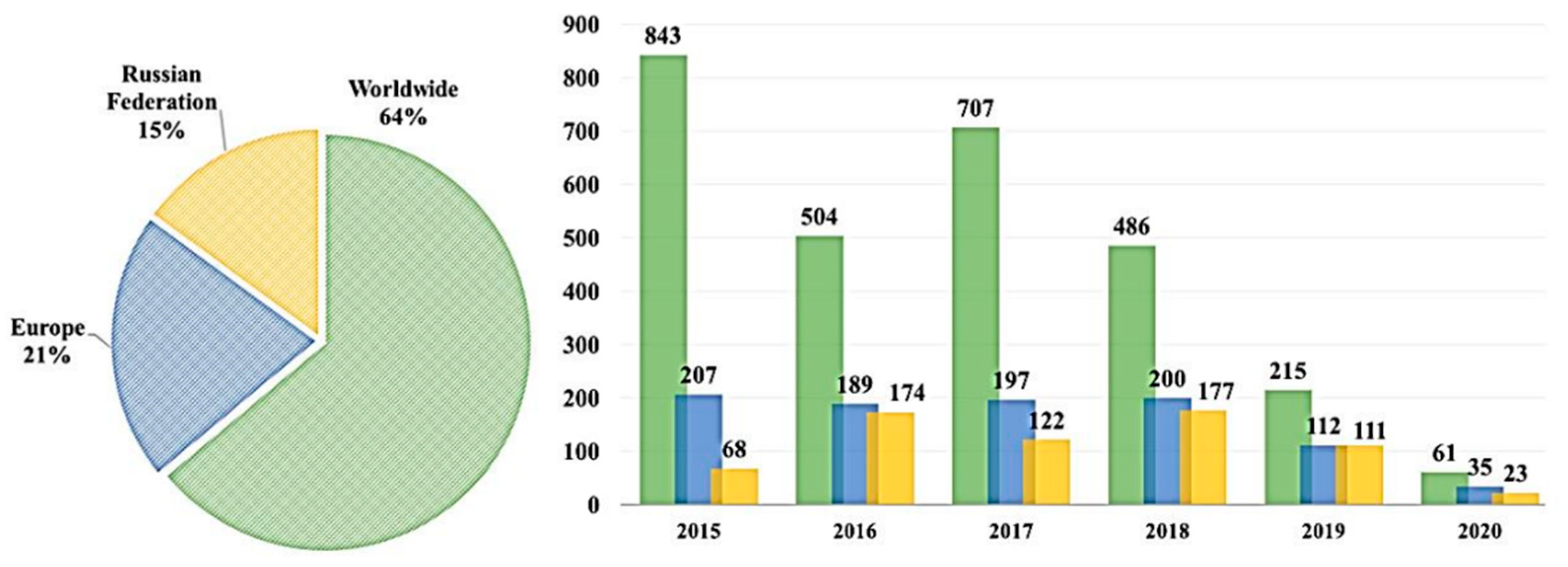
Figure 3.
Percentage of the total research contributed by universities and organizations to the study of in situ combustion.
Figure 3.
Percentage of the total research contributed by universities and organizations to the study of in situ combustion.

Figure 4.
Number of research materials published by various universities and research centers.

Figure 5.
Percentage contribution by scientific field, based on Scopus bibliographic data.

Figure 6.
The temperature profiles for different water–air ratios [35].
Figure 6.
The temperature profiles for different water–air ratios [35].
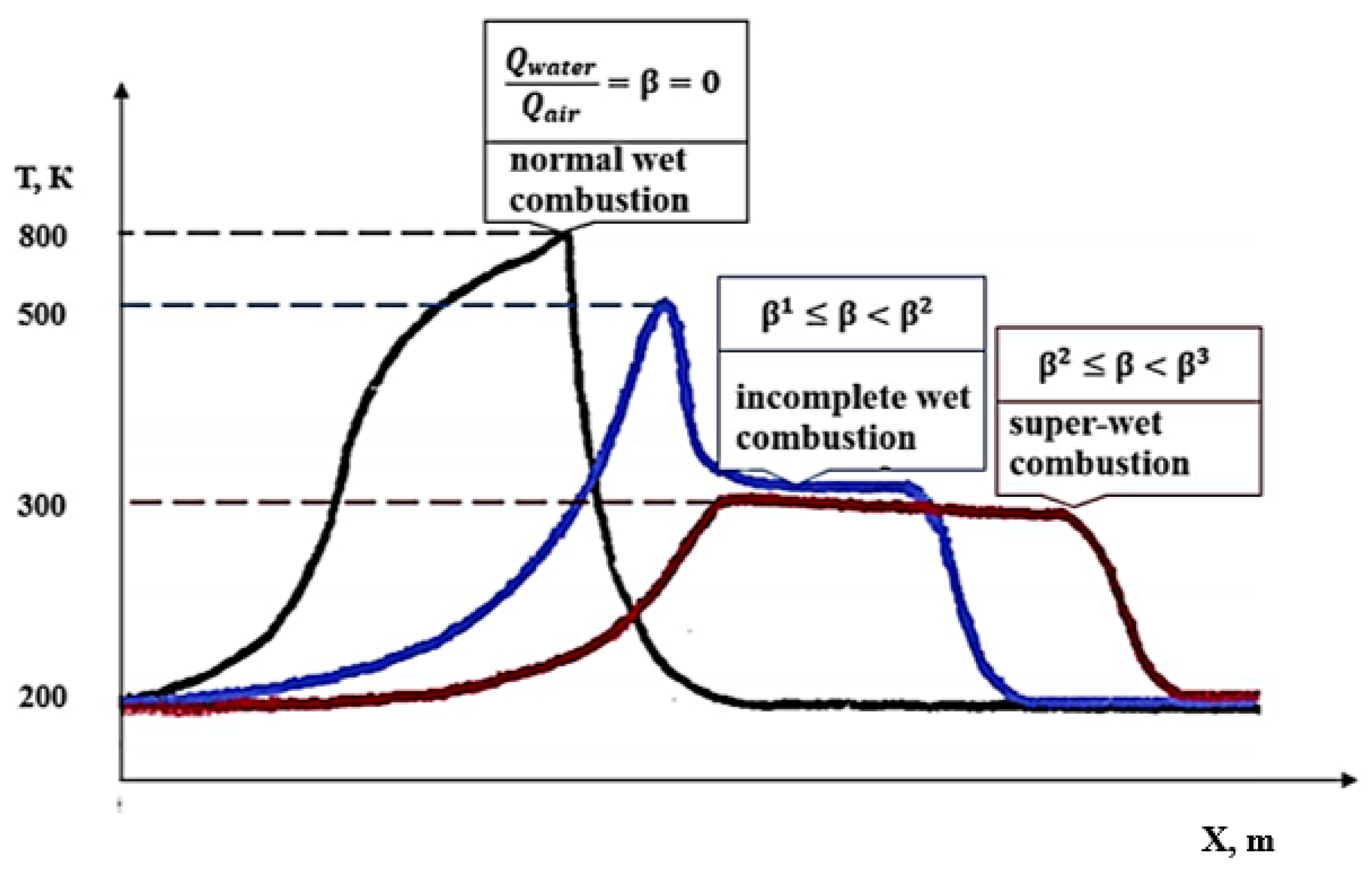
Figure 7.
Basic technologies based on implementing the in situ combustion method.
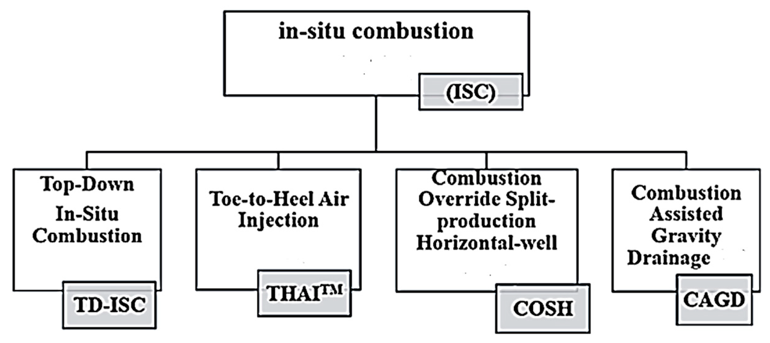
Figure 8.
Schematic diagram of SAGD technology implementation.
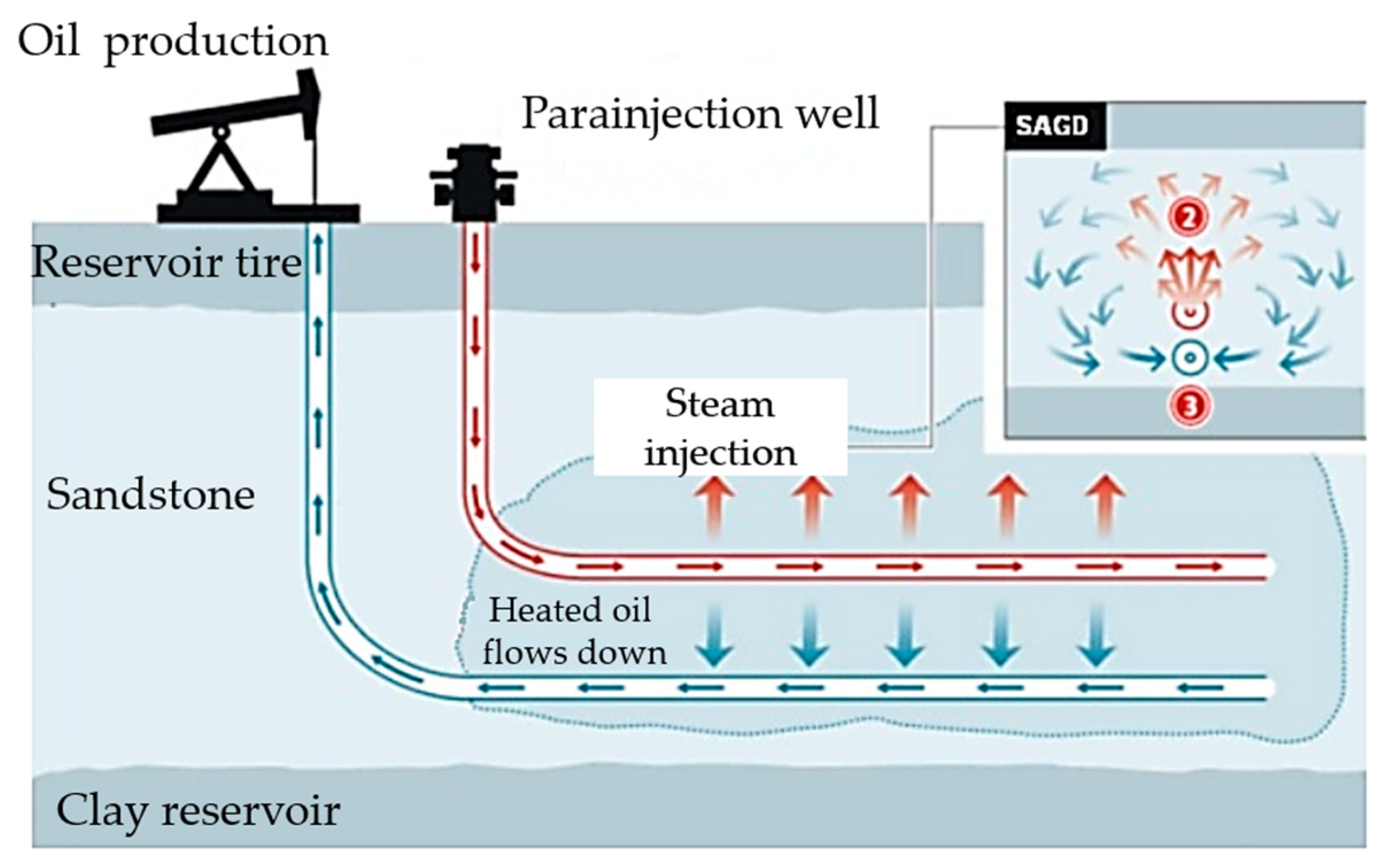
Figure 9.
Basic concept of the in situ combustion studies.

Figure 10.
Schematic diagram of the combustion pipe with nipples for temperature measurements (T1–T5) [58].
Figure 10.
Schematic diagram of the combustion pipe with nipples for temperature measurements (T1–T5) [58].
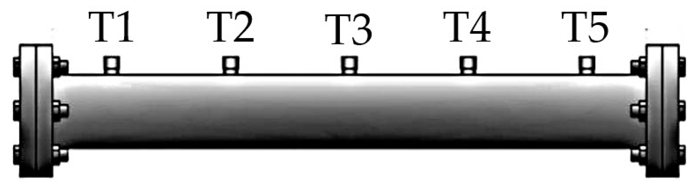
Figure 11.
The diagram of PMTEC [59].
Figure 11.
The diagram of PMTEC [59].
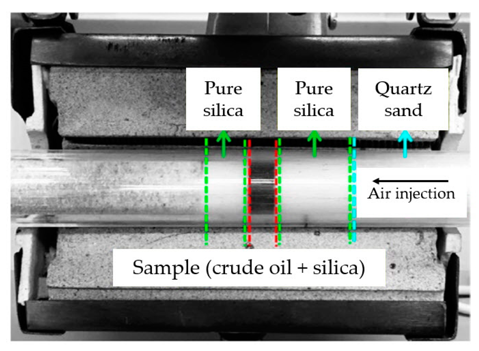
Figure 12.
Experimental unit with a one-dimensional combustion pipe [60].
Figure 12.
Experimental unit with a one-dimensional combustion pipe [60].
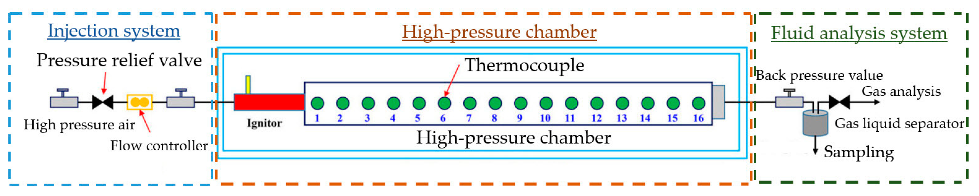
Figure 13.
The diagram of the conical combustion cell unit (a), radial position of internal and wall thermocouple elements, pressure taps, and zone heaters (b) [54].
Figure 13.
The diagram of the conical combustion cell unit (a), radial position of internal and wall thermocouple elements, pressure taps, and zone heaters (b) [54].

Figure 14.
Basic equations of multiphase flow in a porous medium (combined model of heat and mass transfer) [84,85,86].
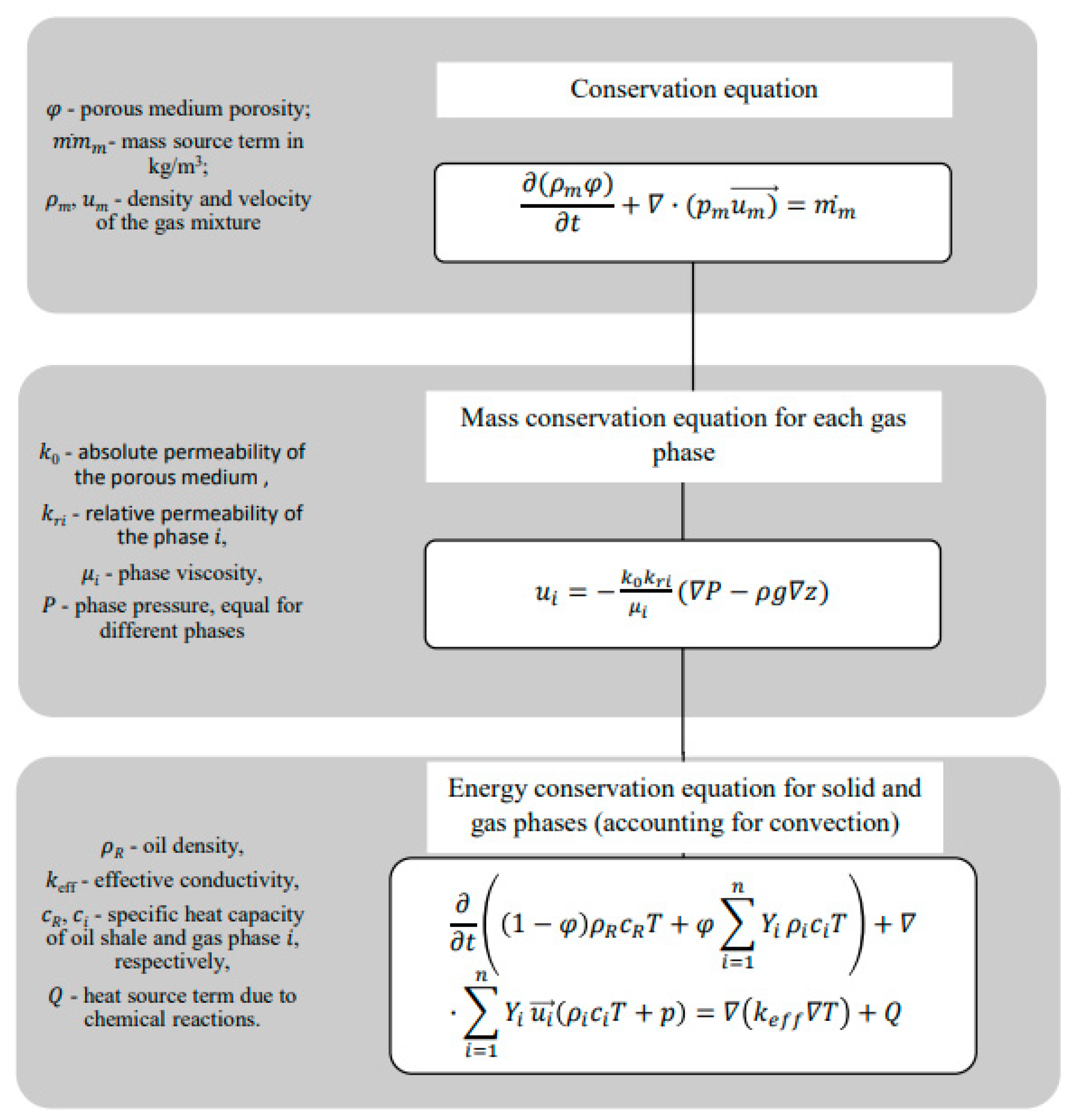
Figure 15.
The temperature distribution diagram for different modes of heat wave propagation [78,79,80]. (a) reaction-trailing front (RTF), (b) reaction-leading front (RLF).

Figure 16.
The comparison of the numerical calculation results from using THAI, THAF, and SAGD technologies for oil production [93].
Figure 16.
The comparison of the numerical calculation results from using THAI, THAF, and SAGD technologies for oil production [93].
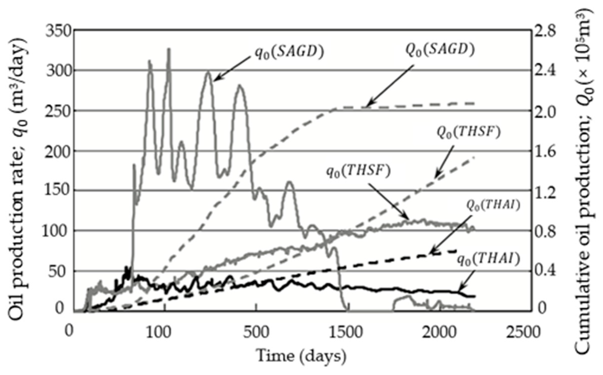

Table 1.
Advantages, disadvantages, and limitations of artificial ignition methods of in situ combustion [39,41].
| Artificial Ignition Method | Advantages | Disadvantages |
|---|---|---|
| Gas burners |
|
|
| Catalytic heaters |
|
|
| Chemical ignition |
|
|
| Steam injection |
|
|
Table 2.
Advantages, disadvantages, and limitations of artificial ignition methods for in situ combustion [63,64].
| Name | Approaches | |||||
|---|---|---|---|---|---|---|
| *1 | *2 | *3 | *4 | *5 | *6 | |
| Capillary forces | ✓ | - | - | - | ||
| ✓ | ± | ✓ | ✓ | ✓ | ✓ | |
| Diffusion forces | ✓ | ✓ (one direction only) | ✓ | ✓ | ✓ | ✓ |
| Mass transfer to viscosity ratio | ||||||
| Reaction rate | - | - | ✓ | ✓ | - | ✓ |
| Gravity forces | - | ✓ | ✓ | ✓ | ✓ | ✓ |
| Dispersion forces | - | ✓ | ✓ | ✓ | - | ✓ |
| Gravity forces to viscosity | - | - | - | ✓ | ✓ | ✓ |
| Dispersed effect | three-dimensional | one-dimensional for the combustion pipe | scattering effect | |||
| model reaction rate prototype speed | ||||||
*1—proposed by Garon et al. (1982, 1986) [65,66] and Kumar and Garon (1988) [67], identical: porous medium, liquid, pressure drop, temperature; geometric similarity; *2—identical: porous medium, liquid, pressure drop, temperature; *3—proposed by Lozada and Farouq Ali (1989) [68], identical: porous medium, liquid, temperature; differences: pressure drop; *4—identical: porous medium, liquid, pressure drop, temperature; geometric scaling; *5—proposed by Lin et al., 1984 [69], identical: porous medium, liquid, pressure drop, temperature, geometric similarity, accelerated reaction rates; *6—identical: liquid, temperature; differences: porous medium, pressure drop; geometric similarity, accelerated reaction rates.
Table 3.
The main promising catalysts for mitigating the temperature oxidation processes [59,76,77,78,79].
| Composition of the Catalyst | Effect | Results |
|---|---|---|
| 1. Clay mixtures of 3 wt% | Catalytic | Controls the combustion front |
| 2. Quartz and mica containing clay | Catalytic | Mica leads to a decrease in activation energy |
| 3. Clinochlor and talc containing clay | Inhibitory | Leads to a delay in the reaction of isomerization and decomposition, as well as in the reaction of oxidative cracking |
| 4. Kaolinite, montmorillonite, mica, and clinochlor containing clay | Catalytic | Controls the combustion front, but does not lead to a shift at the stage of high-temperature oxidation |
| 5. The level of calcite and dolomite | Catalytic | Provides light ignition and significantly reduces the activation energy |
| 6. Copper stearate | Catalytic | Shifts the combustion reactions to a lower temperature range, especially during high-temperature oxidation. Increases the efficiency of coke combustion. |
Disclaimer/Publisher’s Note: The statements, opinions and data contained in all publications are solely those of the individual author(s) and contributor(s) and not of MDPI and/or the editor(s). MDPI and/or the editor(s) disclaim responsibility for any injury to people or property resulting from any ideas, methods, instructions or products referred to in the content. |
© 2023 by the authors. Licensee MDPI, Basel, Switzerland. This article is an open access article distributed under the terms and conditions of the Creative Commons Attribution (CC BY) license (https://creativecommons.org/licenses/by/4.0/).
Share and Cite
MDPI and ACS Style
Minakov, A.V.; Meshkova, V.D.; Guzey, D.V.; Pryazhnikov, M.I. Recent Advances in the Study of In Situ Combustion for Enhanced Oil Recovery. Energies 2023, 16, 4266. https://doi.org/10.3390/en16114266
AMA Style
Minakov AV, Meshkova VD, Guzey DV, Pryazhnikov MI. Recent Advances in the Study of In Situ Combustion for Enhanced Oil Recovery. Energies. 2023; 16(11):4266. https://doi.org/10.3390/en16114266
Chicago/Turabian StyleMinakov, Andrey V., Victoria D. Meshkova, Dmitry Viktorovich Guzey, and Maksim I. Pryazhnikov. 2023. "Recent Advances in the Study of In Situ Combustion for Enhanced Oil Recovery" Energies 16, no. 11: 4266. https://doi.org/10.3390/en16114266
Note that from the first issue of 2016, this journal uses article numbers instead of page numbers. See further details here.