Article

Symmetrical Composite Supercapacitor Based on Activated Carbon and Cobalt Nanoparticles with High Cyclic Stability and Current Load

by
Khabibulla A. Abdullin
1,2,*,
Maratbek T. Gabdullin
3,
Zhanar K. Kalkozova
1,2,
Shyryn T. Nurbolat
1,2 and
Mojtaba Mirzaeian
4,*
1
National Nanotechnology Laboratory of Open Type (NNLOT), Al-Farabi Kazakh National University, Al-Farabi Avenue 71, Almaty 050040, Kazakhstan
2
Institute of Applied Science & Information Technology, Shashkin Str. 40-48, Almaty 050040, Kazakhstan
3
Kazakh-British Technical University, Almaty 050000, Kazakhstan
4
School of Computing, Engineering and Physical Sciences, University of the West of Scotland, Paisley PA1 2BE, UK
*
Authors to whom correspondence should be addressed.
Energies 2023, 16(11), 4287; https://doi.org/10.3390/en16114287
Submission received: 19 April 2023 / Revised: 14 May 2023 / Accepted: 22 May 2023 / Published: 24 May 2023

Abstract

:
Supercapacitors play an important role in a future clean-energy landscape to meet the challenges of existing energy-storage/delivery systems. They suffer from low energy density and are mainly used for the storage/delivery of electrical energy in high power demands. However, improvement of their energy density is vital to develop energy storage systems that can respond to the energy demands of emerging technologies requiring a wider energy/power spectrum. In this article, a symmetrical capacitor is developed from a composite consisting of synthesized activated carbon and cobalt oxide to improve the energy storage performance of the supercapacitor. Uniform distribution and immobilization of cobalt nanoparticles within the composite is achieved by embedding cobalt acetate into the initial resorcinol formaldehyde polymeric aerogels, followed by the pyrolysis of the gel in Ar atmosphere and activation of the carbon in CO2 atmosphere at 800 °C. The activated carbon/cobalt composite is used as the electroactive material in electrode formulation. The electrochemical characteristics of the synthesized electrode materials demonstrates an optimized specific capacitance of 235 F g−1 at a sweep rate of 10 mV s−1 in a three-electrode system. The symmetrical capacitor has a capacitance of 66 F g−1 at 1 A g−1, a very high rate of performance in 10,000 cycle tests, and a rate capability of 24% at 30 A g−1. The capacitor shows a power density of up to 15 Wh k g−1. The presence of cobalt spices makes it possible to optimize the capacitance of a symmetrical capacitor, while the capacitance of a symmetrical activated carbon capacitor cannot be optimized.

1. Introduction

Continuous growth of the contribution of renewable energy to our increasing energy demands, to address the economic and environmental issues related to the use of fossil fuels (i.e., requiring increasing amounts of energy for their extraction and utilization [1], and also their significant role in the upsurge of atmospheric carbon emissions and consequent global warming [2,3]), combined with the around-the-clock emerging of modern technologies and their wide variations of energy and power requirements, compel the development of versatile energy-storage and power supply systems that can offer a wide range of energy and power densities, dealing with the associated issues of poor power quality and the intrinsic intermittency of renewable resources. Since energy storage is the key to opening the door to renewable energy, and where no single device can respond to a wide spectrum of electrical energy storage and delivery time scale, a variety of technologies are needed to be developed and deployed to deal with high-power delivery in short discharge periods and longer time storage/delivery in the times of no energy generation, safeguarding a large-scale supply of energy with wide ranges of power densities and energy densities securely and continuously commensurate with different applications.
In the case of energy storage/delivery in longer time, the lithium-ion battery stands out as a leading technology dominating the markets of portable electronic applications. However, despite its high energy density, good columbic efficiency, minimal self-discharge, and well-developed technology [4], there are still growing concerns about its cost and safety, particularly for large-scale applications in electric vehicles and large-scale energy storage devices. As a result, the development of low-cost and safe batteries with high energy density and power capability providing a long-term energy storage/delivery service is crucial and at the top of the current research agenda of battery scientists to fulfill our future energy demands for a wide variety of applications [5,6,7]. The development of rechargeable aqueous batteries as low-cost energy storage devices has attracted considerable research work in recent years [8,9,10]. Wen et al. have recently developed an aqueous ammonium-ion battery using a monoclinic WO3 nanosphere anode and a γ-MnO2 cathode with outstanding electrochemical performance. The battery has shown an energy density of 64.9 Wh kg−1 and a capacity retention of 95.4% after 5000 cycles at the current density of 3.0 A g−1 [11]. By using a V2O3-carbonized dictyophora composite cathode as the electroactive material in an aqueous zinc-ion battery, Zhou et al. have also achieved an excellent capacity of 289 mAh g−1 with 89% capacity retention after 1000 cycles at a current density of 50 mA g−1 and an outstanding capacity of 170 mAh g−1 at a current density of 1 A g−1 [12]. These show the potential of rechargeable aqueous batteries with the advantages of simple manufacturing process, outstanding safety, environmental friendliness, and high ionic conductivity.
In the case of energy storage/delivery in short times, supercapacitors are devices with the capability of absorbing and delivering large amounts of energy over short timescales, offering enormous power density when compared to other energy storage technologies. As an integral part of energy storage and delivery systems, they play a crucial role in meeting the challenges of contemporary energy storage and power delivery systems in a future clean-energy landscape. Their excellent power delivery characteristics make them an ever-more important class of energy storage technologies with the capability of storing enough energy for a range of industrial applications when requiring a sudden surge of energy for a short period of time, such as automotive acceleration and braking in electric vehicles [13,14,15], pulsed power applications in telecommunications and microgrids [16,17,18], portable products and uninterruptible power supplies [19], solar arrays [20], and wind turbines [21]. They are utilized in hybrid energy storage systems complementing other high energy density devices such as batteries by providing periods of pulsed power that otherwise would be challenging to achieve when needed through pushing the device to the edge of its instability [22]. Despite their superb rate capability and high power performance, there are still several shortcomings associated with their applications that include the requirements of high energy density and extended energy delivery times.
Supercapacitors store energy in the form of an electric charge in three main fashions of (i) an electric double-layer capacitor (EDLC) in which the electronic charges accumulate on the surface of the electrodes at the electrode and electrolyte interface by non-Faradaic interactions (electrostatically). This is achieved through the transfer and formation of a double layer of associated ions at the interface within the electrolyte responsible for a large amount of charge that the supercapacitor can store [23]. Therefore, a higher specific surface area of the electrode results in a greater specific capacitance and, accordingly, a greater energy density according to E = 1 2 C V 2 , where E is the energy density, C is the specific capacitance, and V is the operating voltage. Hence, the development of porous nanoelectrode materials is one of the effective strategies for enhancing the energy density of EDL supercapacitors.
Due to the ease of production and control of their porous structure allowing high porosity, huge specific surface area, controllable pore-size distribution facilitating the electrolyte access to the internal pores, combined with their high electric conductivity, tunable wettability, chemical inertness, and cost-effectiveness, polymer-based carbons [24] and activated carbons [25,26,27] have been considered and used as the most apposite electrode materials for capacitive energy storage in supercapacitors for a long period of time. Because of non-Faradaic charge-storage processes, which store charges through static electricity only, the structural changes of the electroactive material during the charge/discharge process of EDL supercapacitors are insignificant. This results in very high-energy-storage efficiencies of above 95% with excellent cyclic stability of several hundreds of thousands of times without considerable loss of the energy storage capacity of EDLCs and improves their power performance through rapid energy uptake and delivery, providing them with energy storage solutions with exceptional rate capability, high power performance, and the greatest lifetime when fast power delivery is required [22,28,29]. However, because of the mechanism of electrostatic surface charging, EDLCs still experience low energy densities, which greatly restrict their applications to meet the higher requirements for large-scale implementations of future systems needing high power density with increased ability to store energy so that it could be used for a longer term. (ii) Pseudocapacitors (PC), in which energy in the form of electric charges is stored within the electroactive materials utilized in their electrode formulation undergoing fast and reversible Faradaic reduction–oxidation reactions on the surface or in a shallow depth within the near-surface layer of the electrode materials (according to their various potentials called pseudo-capacitive behavior). In PCs, electric charges transfer from the surface of the electrode to the electrolyte ions and from the electrolyte ions to the electrode surface reversibly with limited diffusion of ions where ion diffusion length is significantly shortened when compared to battery storage in which bulk solid-state ion diffusion occurs [30,31]. These result in a passage for Faradaic current on the double layer, contributing to the increase in energy density at the expense of poor cyclability and lower power density compared to EDLCs [32]. Electroactive materials such as metal oxides or conductive polymers are prevailing electrode materials used in PCs because of their pseudo-capacitive behavior [29,33]. Conducting polymers such as polyaniline, polypyrrole, polythiophene, and their derivatives have been used as electrode materials with pseudo-capacitive properties in PCs and have shown high gravimetric and volumetric pseudo-capacitance; however, their initial performance wanes as a result of their limited stability during cycling [29,34,35,36]. A wide range of transition metal oxides exhibiting various oxidation degrees including RuO2 [37], Fe3O4 [38], MnO2 [39], MoO2 [40], NiO [41], V2O5 [42], and Co3O4 [43] have also shown promising pseudo-capacitive charge storage results in the past couple of years, yet a poor cyclability associated with their structural disintegration because their swelling and shrinking during cycling has hindered their full utilization for practical application of PCs. (iii) Hybrid capacitors, in which both Faradaic and non-Faradaic charge storage mechanisms are combined in order to address the energy storage limitations of EDLCs and the cyclic stability and power-handling limitations of PCs, promoting specific capacitance in a single device. Depending on the combination of a Faraday electrode acting as the energy source with a non-Faraday capacitor-type electrode acting as the power source, three types of hybrid supercapacitors including asymmetric supercapacitor, battery-type supercapacitor, and composite hybrid supercapacitor emerge. In asymmetric and battery-type supercapacitors, the charge storage mechanisms of the two electrodes are different, and each of the former mechanisms of Faradaic and non-Faradic behaviors occurring independently on positive and negative electrodes (depending on the type of the device) are combined in a single device, providing high energy density and power density for the device at the same time. This is through the benefiting from the advantages of the two different electrode materials operating at different potential windows in the device, while a composite hybrid supercapacitor is a symmetric capacitor in which both electrodes are the same, using a composite material consisting of carbonaceous material incorporated with pseudocapacitive materials such as transition metal oxides as the electroactive material.
Due to the formation of effectual active sites, a larger electrode/electrolyte interfacial area, and quicker transfer of active species, which speeds up the electrochemical reaction, the metal embedding in carbon has been used for a long time to achieve highly efficient electrocatalysts [44,45,46,47]. For this purpose, embedding transition metal oxides in carbon to prepare composites made of metal oxide nanoparticles and carbonaceous materials has been highlighted as a promising and cost-effective method for the preparation of electroactive composite materials to improve their electrical conductivity, specific surface area, electro-active sites, and chemical stability and to limit the aggregation of metal oxide nanoparticles [33,48,49]. The porous carbon in the metal oxide composite not only contributes to EDLC charge storage but also, in comparison to bulk metal oxide, acts as a support for the metal oxide nanoparticles contributing to a higher surface-specific area, good electric conductivity, and good wettability of the active materials by the electrolyte. It also facilitates a better transfer of ions in the electrolyte and a better use of the active pseudocapacitive materials at high-rate charging–discharging, where the satisfactory electro-active sites ensure high pseudo-capacitive performances and cyclic stability [33,50,51,52,53].
Due to its distinctive nanostructure, huge internal surface area, good mechanical strength, and flexibility, nanocellulose has also been utilized as the base material for the fabrication of electrodes for hybrid supercapacitors [54]. Although it is not electrically conductive, its pretreatment to convert into carbon materials or its incorporation with other conductive components such as conducive polymers, nanocarbons, and metal oxides have resulted in the development of nanocellulose-based conductive hybrids as favorable environmentally friendly electrode materials for supercapacitor applications [55].
Enormous research work and review papers have been published on the development of electrode materials, their storage mechanisms, the fabrication of electrodes, and also the proper design of devices for EDLCs [56,57,58,59,60,61,62], PCs [63,64,65,66,67,68,69,70,71,72,73,74,75,76,77], and hybrid capacitors [78,79,80,81,82,83,84,85,86].
Research that could potentially offer additional cost and performance benefits for supercapacitor development is highly relevant. Symmetrical capacitor designs, where both electrodes are made of the same material and have the same mass and area, have a simplified manufacturing process and require simpler manufacturing processes compared to asymmetric systems. Therefore, symmetrical capacitor designs are attractive in terms of efficiency in mass production. However, the capacitance of symmetrical capacitors made from activated carbon (AC), which is the most common supercapacitor material, cannot be optimized. This is because the potentials of the anode and cathode electrodes of an AC capacitor are not symmetrical with respect to the potential of a fully discharged capacitor. The operating range of the potentials is much narrower at positive potentials than at negative ones [87]. It is also characteristic for activated carbon electrodes that their specific capacitance at positive and negative potentials differs significantly. This is due to the difference in the mechanisms of interaction of positive and negative electrolyte ions with the electrode material, the presence of electrically charged radicals on the surface of the electrodes, and in the near-surface region capable of redox reactions. Accordingly, to optimize the operating modes, it is necessary to satisfy a certain ratio between the values of the operating voltages and capacitances of the positive and negative electrodes of the capacitor [88]:
Q = C P U P = C N U N   o r   U N = U P C P C N
where UP, CP and UN, CN represent the operating potential window and capacitance of the positive and negative electrodes, respectively. Since for a symmetric activated carbon capacitor in an alkaline electrolyte, the value of UP is less than UN, as well as CP being less than CN, condition (1) cannot be fulfilled. To achieve the optimization condition, it is necessary to increase the mass of the active material of the positive electrode in comparison with the mass of the negative electrode [87,88].
In this work, resorcinol formaldehyde-based activated carbon/cobalt oxide composites with different cobalt loadings were synthesized by polycondensation reaction between resorcinol (R) and formaldehyde (F) in the presence of cobalt acetate to prepare RF/cobalt acetate polymeric gels followed by the carbonization of the polymeric gels at 800 °C in Ar atmosphere and activation of the cobalt-loaded carbons in CO2 atmosphere at 800 °C. The activated carbon (AC) composites were used as electroactive material in the electrode formulation. A symmetrical capacitor was fabricated with high cyclic stability and current load, where both electrodes of the capacitor were made of an AC composite with embedded cobalt nanoparticles using a 3.5 M KOH solution as the electrolyte. The presence of these nanoparticles has little effect on the capacitance of the negative electrode; at the same time, the capacitance of the positive electrode can vary in a controlled manner to achieve optimal conditions for creating a symmetrical capacitor.

2. Materials and Methods

2.1. Materials

Resorcinol (C6H4 (OH)2, 98%), formaldehyde ((HCHO), 37% solution), sodium carbonate anhydrous (Na2CO3, ≥99.5%), reagent-grade cobalt (II) acetate tetrahydrate (C4H6CoO4·4H2O), carbamide, and N-methyl-2-pyrrolidone (NMP) were purchased from Sigma Aldrich ( Gillingham, Dorset, UK). The reagent acetone was purchased from VWR International Ltd. (Lutterworth, Leicestershire, UK). The PVDF powder Kynar was purchased from PolyK (State College, PA, USA). The used deionized water (18.2 Mohm × cm) was produced by the AQUAMAX-Ultra 370 Series water purification system (YL Instrument Co., Anyang, Republic of Korea).

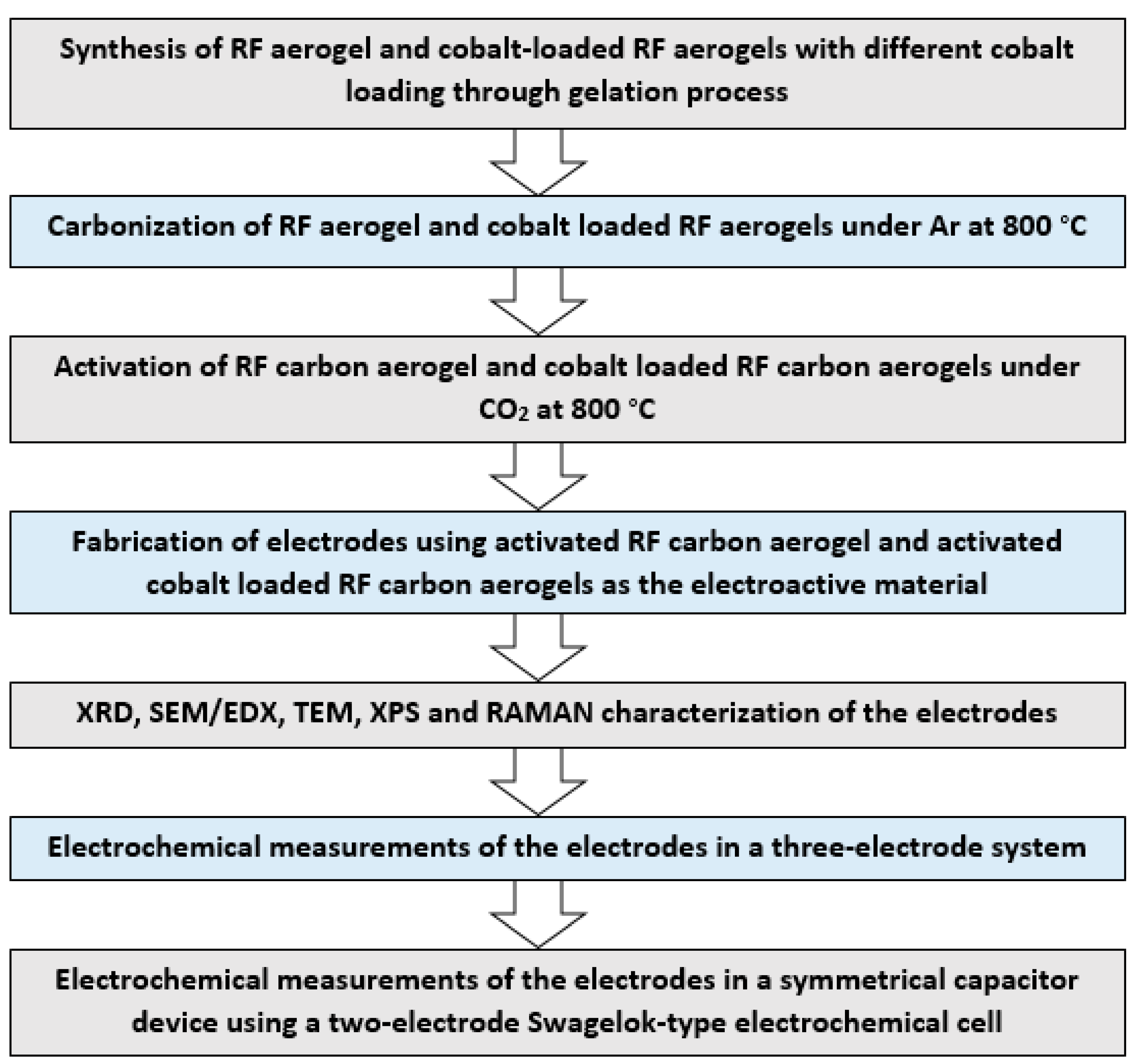
2.2. Preparation of the Activated Carbon–Cobalt Composite (Co@AC)

Resorcinol/formaldehyde aerogel and cobalt-loaded resorcinol (R) formaldehyde (F) aerogels were prepared by mixing the predetermined amount of resorcinol, sodium carbonate as catalyst (C), and cobalt acetate as the cobalt source in deionized water (W). The mixture was mixed vigorously for 45 min at room temperature. Formaldehyde was added with continuous stirring for another 45 min. The molar ratios of resorcinol to formaldehyde (R/F) and resorcinol to catalyst (R/C) and the ratio of resorcinol to water (R/W) in g mL−1 were kept constant at 0.1, 200, and 0.5, respectively. The molar ratio of cobalt acetate to resorcinol varied between 0 and 1. The obtained solutions were placed in sealed Duran bottles to avoid water evaporation during the gelation process, and the sealed bottles were placed in the oven and kept at 25 °C for 24 h to initiate the gelation process, followed by keeping them at 60 °C for 48 h and at 80 °C for another 72 h to ensure the formation of a well-developed three-dimensional gel structure after the completion of the gelation process. The synthesized light-brown aqua gels were cut into small pieces and submerged in acetone for 4 days for solvent exchange to completely remove water from the hydrogels’ porous structure prior to their drying. The final aerogels then were obtained by drying in a vacuum oven at 5 mbar and 40 °C for 4 days for the complete removal of acetone from the internal pores of the solvent-exchanged gels without any shrinkage.
The dried RF and cobalt-loaded RF aerogels were carbonized at 800 °C in a tubular furnace according to the following method: in each carbonization experiment, 3 g of aerogel was placed in a ceramic boat and purged for 30 min with Ar at 200 mL min−1 at room temperature before commencing the heating program. The temperature of the furnace was increased to 150 °C at 5 °C min−1 and maintained for 30 min. It was then increased to 450 °C at 5 °C min−1 and held for another 30 min before heating the sample to the final carbonization temperature of 800 °C at 10 °C min−1. The sample was then kept at the carbonization temperature for 3 h. After the completion of carbonization, the furnace was cooled to room temperature in flowing Ar.
The activated carbon aerogel and activated cobalt-loaded carbon aerogels were prepared by their mild oxidation in CO2 atmosphere at 800 °C. A sample of carbon/cobalt-loaded carbon was placed in a ceramic boat and located at the center of the furnace. The sample was first purged with Ar flowing at 200 mL min−1 for 30 min prior to heating and, then, heated to the activation temperature of 800 °C at 10 °C min−1. At this stage, gas was changed to CO2, and the sample was kept at at 800 °C in CO2 atmosphere for 3 h. After the completion of activation, the gas was switched to Ar, and the sample was cooled down to room temperature under Ar flowing at 200 mL min−1.

2.3. Preparation of the Co@AC Electrode

To prepare the electrode, the synthesized Co@AC composite was mixed with PVDF powder in a weight ratio of 9:1. Since the particles of the Co@AC composite were very small, no carbon black was used. A certain amount of NMP was added to the Co@AC + PVDF mixture and mixed in an agate mortar. The solution was uniformly applied to the nickel foam (NF), and the electrodes were dried first in the air and then in a vacuum oven at 70 °C for 3 h. The mass of the active substance of the Co@AC/NF electrode was determined by weighing and ranged from 4 to 10 mg cm2. To create a symmetrical supercapacitor, two identical electrodes were cut from an electrode with a larger area. After pressing, the electrodes were ready for measurements.

2.4. Characterization

The phase structure of the samples was studied using a MiniFlex X-ray diffractometer (Rigaku, Tokyo, Japan) operating with CuKα radiation at a wavelength of 1.5418 Å at an accelerating voltage of 40 kV and a current of 15–40 mA. Sample morphology was evaluated by a scanning electron microscope (SEM) Quanta 200i 3D (FEI, Hillsboro, OR, USA) and transmission electron microscopy (TEM) JEM-2100 (JEOL, Tokyo, Japan). The chemical composition of materials was studied using a NEXSA X-ray photoelectron spectrometer (Thermo Scientific, Waltham, MA, USA). Raman spectra were investigated using an NTEGRA Spectra spectrometer (NT-MDT) with a solid-state laser exciting at 473 nm.

2.5. Electrochemical Measurements

The electrochemical properties of the prepared electrodes were studied by the standard three-electrode system using a P-40X-FRA-24M potentiostat (Elins, Chernogolovka, Russia). The three-electrode system consists of a working electrode, a reference electrode (Ag/AgCl), and a platinum counter electrode. The electrochemical characteristics of the supercapacitor electrodes were studied in 3.5 M KOH electrolyte by cyclic voltammetry (CV), galvanostatic charge-discharge (GCD), and electrochemical impedance spectroscopy (EIS) measurements in the frequency range of (0.1 Hz–500 kHz) at a sinusoidal potential amplitude of 20 mV.
The electrochemical characteristics of the capacitor were studied using a two-electrode Swagelok-type electrochemical cell with a 3.5 M KOH electrolyte. Both anode and cathode are made up of Co@AC, and a filter paper was used as the separator. The capacitance of the capacitor was measured in a two-electrode circuit by the CV and GCD methods in the voltage range of 0 V up to 1.7 V. The specific capacitance was calculated from the measurement results of CV according to Equation (2):
C s = 1 2 m ν ( V m a x V m i n ) I V d V ,
where Cs is the specific capacitance (F g−1), m is the mass of the electroactive material of the electrode (g), ν is the scan rate (V s−1), Vmax − Vmin is the potential window (V), I is the current (A), and integration is performed over one CV cycle. The results of the GCD measurements were also used to calculate the specific capacitance Cs (F g−1), according to Equation (3):
C s = I d t m Δ U ,
where m is the mass of the electroactive material of the electrode (g), I the discharge current (A), dt the discharge time (s), and ΔU the voltage drop (V).
Figure 1 shows a flowchart of the sequence of steps including the preparation of electroactive materials, fabrication and characterization of the electrodes, and electrochemical measurements of the as prepared electrodes and the measurement of their electrochemical performance in a symmetric supercapacitor device.

3. Results

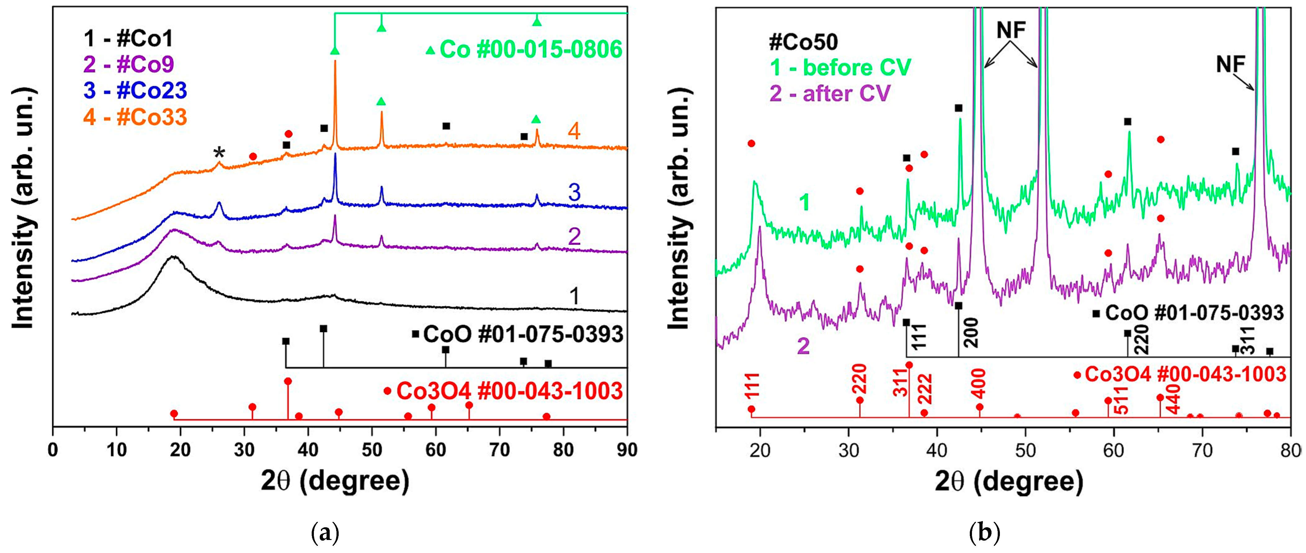
3.1. XRD Analysis of the Co@AC Composite

Co@AC samples containing 1, 5, 9, 23, 33, and 50 mole percent of cobalt acetate in the initial charge were synthesized and designated as #Co1, #Co5, #Co9, #Co23, #Co33, and #Co50, respectively. The X-ray diffraction (XRD) patterns of the #Co1 ÷ #Co50 composites are shown in Figure 2. The main XRD peaks (Figure 2a) correspond to metallic cobalt (JCPDS card no. 00-015-0806). There are also low-intensity reflections that can be attributed to the cobalt oxide phases CoO (JCPDS card no. 01-075-0393) and Co3O4 (JCPDS card no. 00-043-1003). The peak marked with an asterisk (*) can be attributed to graphitized carbon. The intensity of the cobalt reflections increases with an increase in the content of the cobalt acetate precursor in the initial charge. The average cobalt particle size estimated by the Williamson–Hall method was ~40 nm.
Figure 2b shows the XRD patterns of the #Co50 electrodes on nickel foam, both before (1) and after (2) CV measurements. Reflections of cobalt nanoparticles (cubic phase) were masked by intense nickel reflections. Cobalt reflections of the hexagonal epsilon phase were not detected. It can be seen that the CoO and Co3O4 phases are present in the samples, and the relative content of the Co3O4 phase increases after in situ oxidation.

3.2. Surface Morphology Study
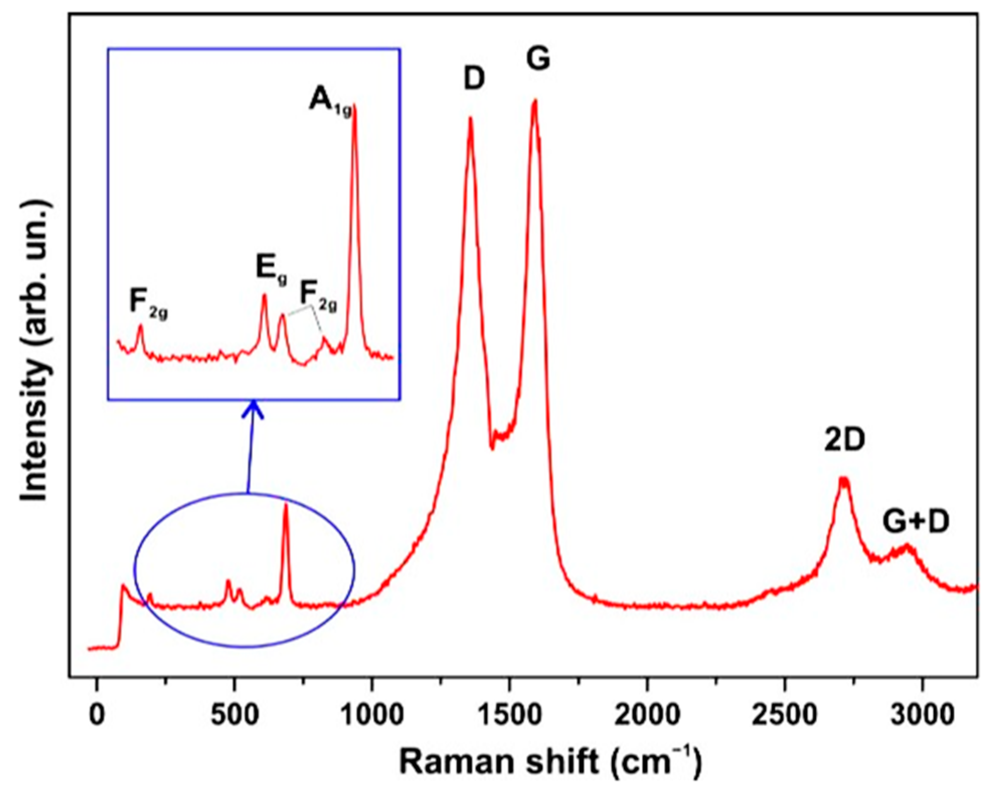
The morphology and microstructure of the Co@AC composite were characterized by SEM and TEM. SEM images (Figure 3a) show that the structure of the composite consists of porous activated carbon particles interspersed with cobalt particles (light spots in Figure 3a). TEM images (Figure 3b) show that the AC particles (semitransparent particles in Figure 3b) are loosely bound to each other and have a size of about 20–40 nm. Cobalt particles (dark particles in Figure 3b) are about the same size, and they are evenly distributed in the carbon matrix.
The energy-dispersive X-ray (EDX) microanalysis method was used to determine the elemental composition of the composites. In addition to the main elements, carbon and cobalt, the samples contained small amounts of sulfur and oxygen. The EDX spectrum of sample #Co33 is shown in Figure 4; this sample was found to contain 95.2% carbon and 4.8% cobalt. The inset of Figure 4 shows the dependence of the cobalt content on the amount of cobalt acetate in the charge. It can be seen that the dependence is linear; therefore, the desired concentration of cobalt in the Co@AC composite can be set during the synthesis of the composite.

3.3. Raman Spectra

The Raman spectra of Co@AC (Figure 5), measured at a low excitation power of 0.035–0.122 mW, demonstrate a Raman spectrum characteristic of activated carbon and a weak spectrum corresponding to the Co3O4 spinel [89,90].
Note that the Raman spectrum of Co3O4 was not observed in most of the samples. Figure 5 shows the Raman spectrum for a #Co50 sample with the highest cobalt concentration.

3.4. Chemical Characterization

To confirm the chemical composition of the nanocomposite, the XPS analysis of the #Co50/NF composite electrode before and after capacitive measurements was performed. Figure 6 illustrates the high-resolution XPS spectra and the characteristic peaks of cobalt Co 2p (Figure 6a) and oxygen O 1s (Figure 6b). Each of the Co 2p3/2 and Co 2p1/2 peaks in the Co 2p spectrum were deconvoluted into two components corresponding to the Co2+ and Co3+ states. In the initial samples, the Co2+ state predominates, but its contribution is significantly reduced after capacitive measurements because of in situ oxidation.
The O 1s spectrum (Figure 6b) contains three characteristic bond peaks. The OI line at 529.5 eV is associated with lattice oxygen or oxygen in the metal oxide. The OII peak at 531.1 eV corresponds to hydroxide and per-hydroxide species, and the OIII peak at ~533 eV can be associated with structural water. It can be seen that, after CV measurements, there is an accumulation of hydroxide and per-hydroxide species and structural water.

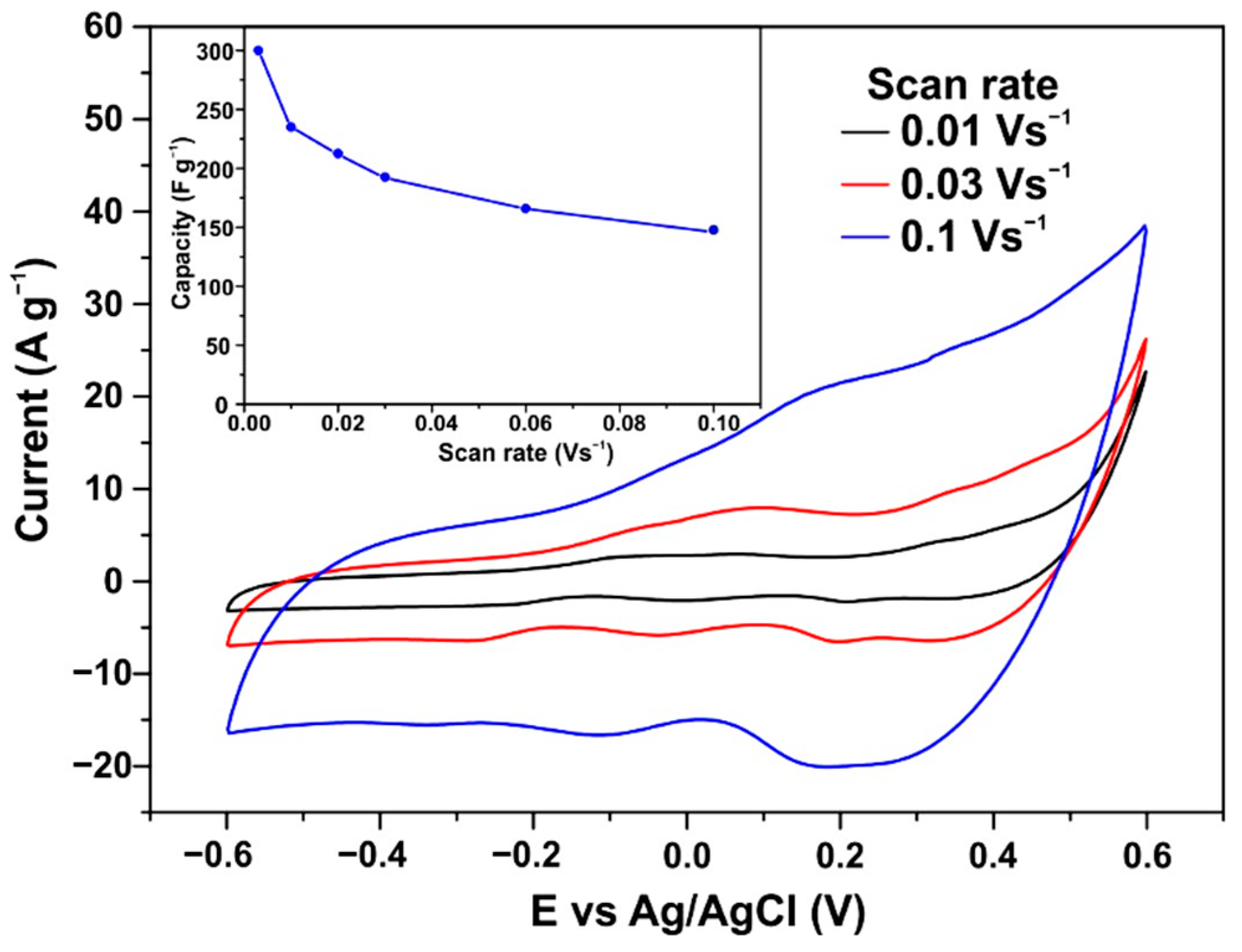
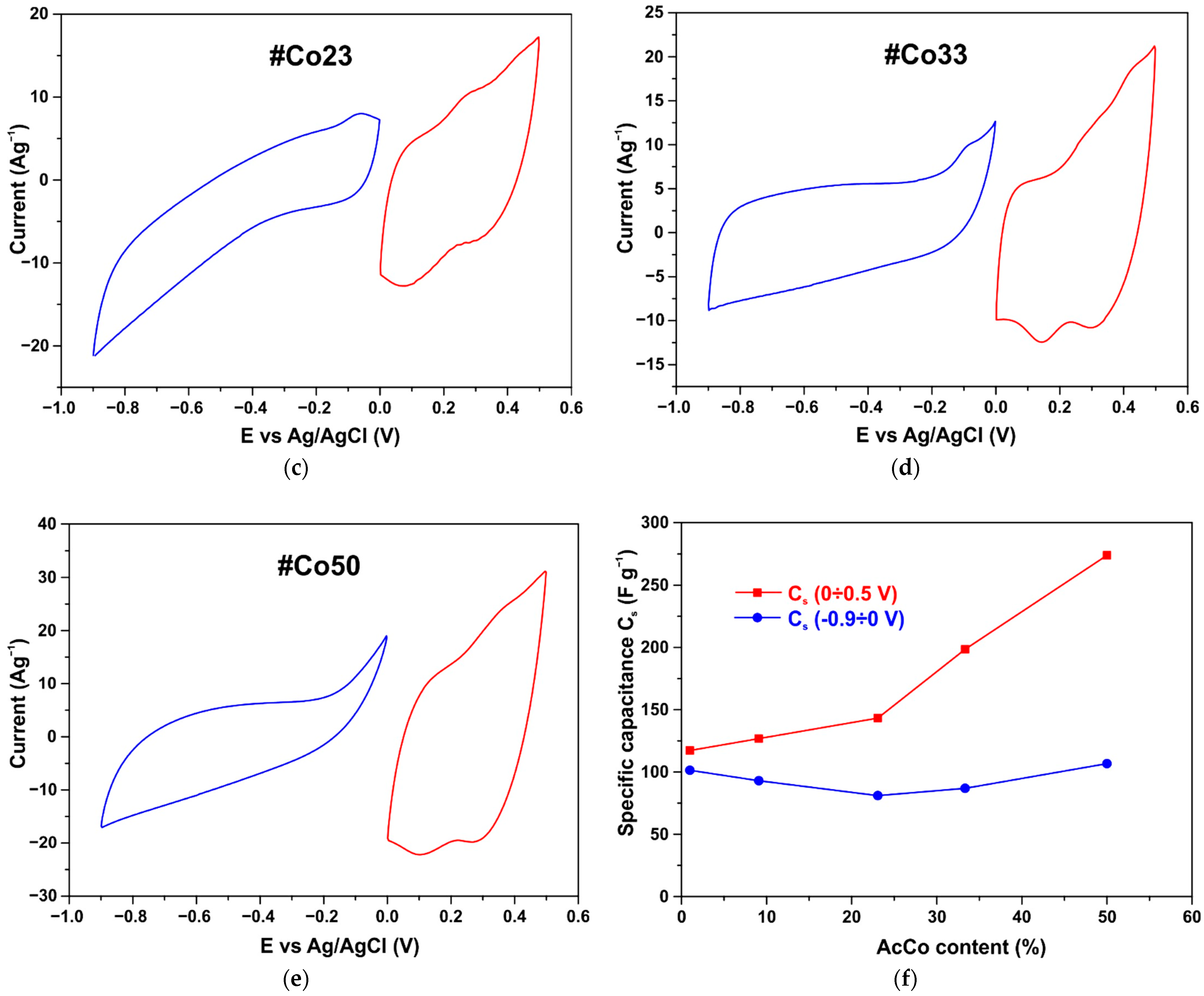
3.5. CV Measurements

The as-prepared electrodes’ electrochemical performance was investigated using cyclic voltammetry (CV) measurements. The CV curves of an electrode made from the #Co50 composite are depicted in Figure 7. CV curves were measured in 3.5 M KOH electrolyte at a sweep rate from 10 to 100 mV s−1 in the potential window of −0.6 to 0.6 V. An electrode with a loading mass of 8 mg and an area of 1 cm2 showed a capacitance of 1.88 F at a scan rate of 0.01 V s–1. This corresponds to a specific capacitance of 235 F g–1. A characteristic feature of CV curves is the fact that in the negative potential region, the CV curves are similar to those of activated carbon electrodes, while in the positive region, the CV curves show redox peaks characteristic of electrodes with cobalt oxide [91]. As we can see from Figure 7, the introduction of cobalt oxide results in a drastic increase in capacitance in the positive potential range, although the range of the operating potential is not wide.
Figure 8a–e show the CV curves of five samples with different concentrations of cobalt, and Figure 8f shows the dependence of the specific capacity vs. the content of cobalt acetate in the original charge. As seen, the specific capacitance in the negative potential range of −0.9 V to 0 V remains approximately the same for all samples, regardless of the cobalt content. In the positive potential range (0–0.5 V), even at a low cobalt concentration, the specific capacitance is higher than in the negative one. The CV curves show redox peaks because of the presence of cobalt particles. The capacitance in the positive potential region grows progressively with an increase in the cobalt content. Therefore, by changing the cobalt composition of the composite, it is possible to set the value of the specific capacitance and provide the conditions for optimizing a symmetrical capacitor according to Equation (1). The composition of the #Co50 composite is close to optimal since the ratio between the operating ranges of positive (UP = 0.45 V) and negative (UN = 1 V) potentials is approximately equal to the ratio of capacitances CN = 106.7 F g−1 and CP = 274.0 F g−1.

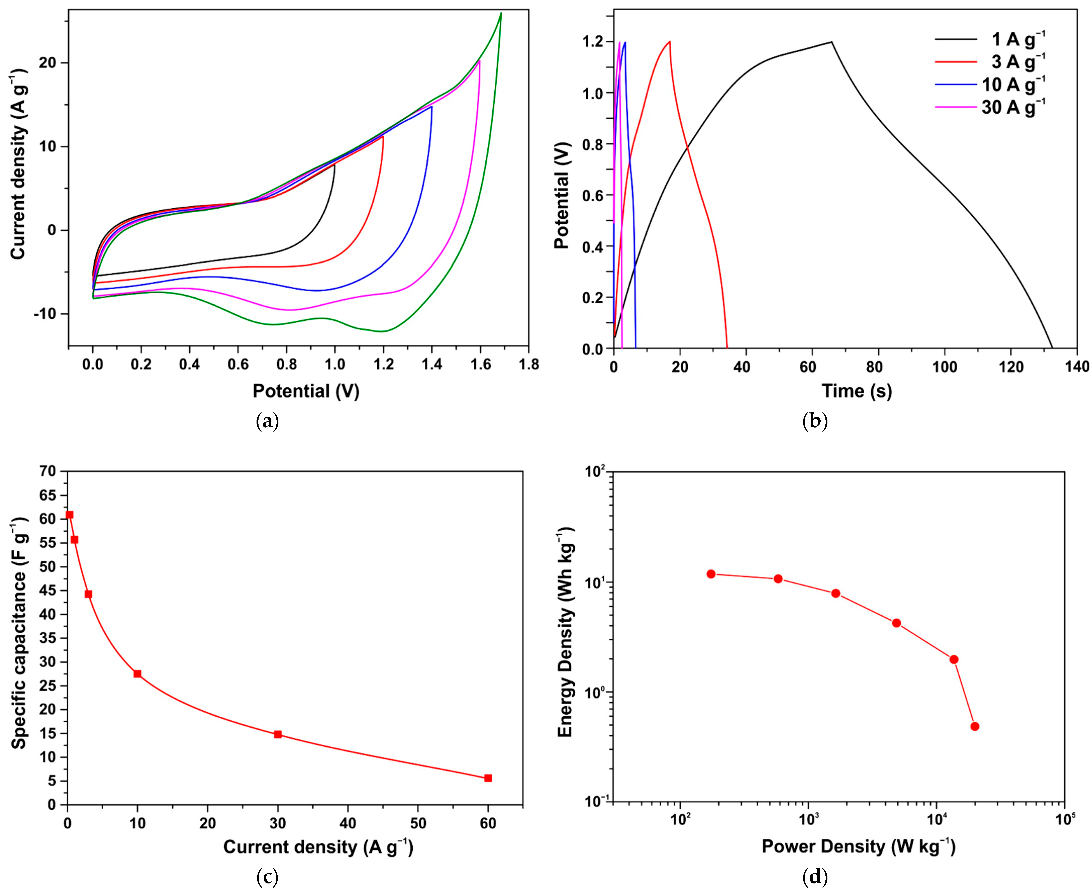
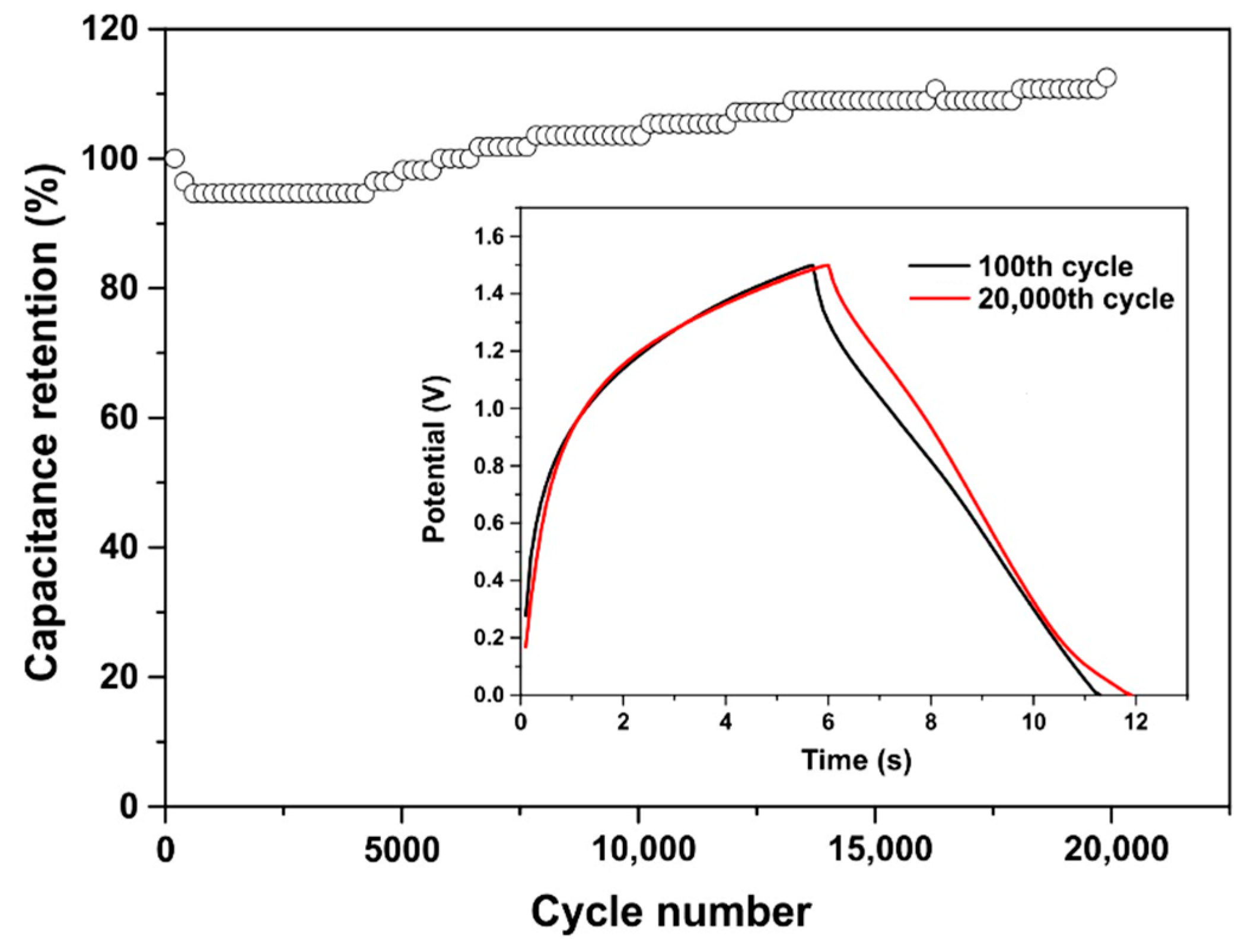
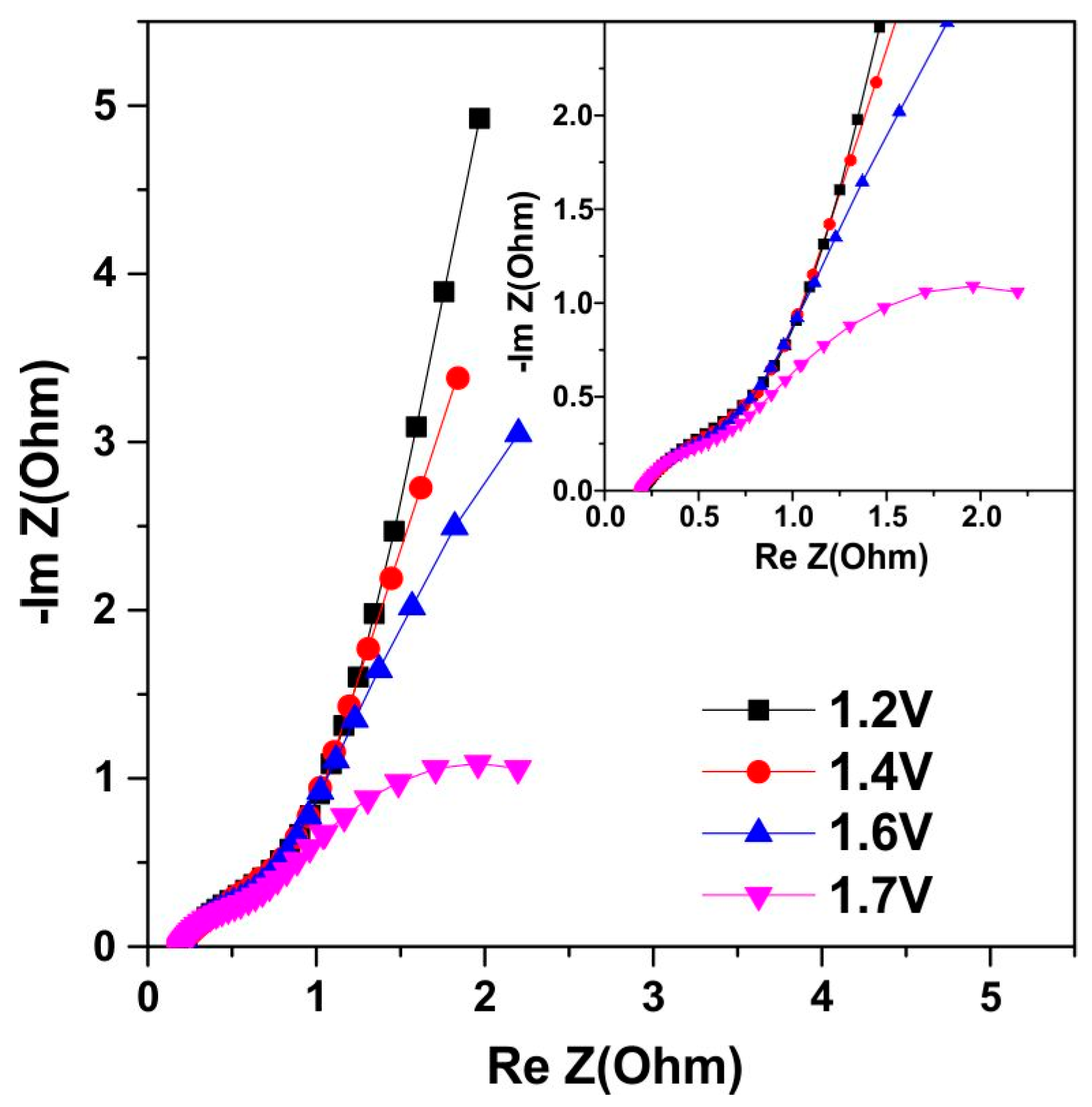
3.6. Symmetrical Capacitor Characterization

The properties of the obtained composite as a material for the manufacture of a symmetrical capacitor were investigated. Two identical electrodes with an area of 1 cm2 were fabricated. The electrodes were then placed in a two-electrode Swagelok-type electrochemical cell with a 3.5 M KOH electrolyte and a PTFE separator. The CV characteristics of the #Co50/NF symmetrical capacitor at different voltage windows are shown in Figure 9a. The curves show a quasi-rectangular shape without distortion when measuring CV curves in the range from 0 to 1 V. Higher voltages give rise to quasi-capacitive behavior, which is the main contributor to the capacitance of the capacitor. Under dynamic conditions, at a scan rate of 0.1 V/s, no decomposition of the electrolyte is observed up to a voltage of about 1.6 V. As shown in the EIS experiments below, under quasi-static conditions, the operating potential window decreases to 1.2–1.3 V.
Measurements using the GCD method confirm the capacitive behavior of the Co@AC composite capacitor. Figure 9b shows that the charge–discharge curves for a capacitor with a mass load of 6 mg are close to straight lines. Thus, the Faraday redox reactions on the positive electrode are clearly manifested in the CV curves (Figure 7 and Figure 8) and characterize the electrode as a battery type; however, a capacitor where the negative electrode is a capacitive electrode exhibits GCD curves typical of hybrid supercapacitors [21,37,91]. Figure 9c shows that the capacitor can handle very high current loads up to 60 A g−1. The specific capacitance at 30 A g−1 with respect to the capacitance at 0.3 A g−1 is 24% (Figure 9c). The Ragone plot corresponding to these GCD data is shown in Figure 9d.
Cyclic stability is a very important aspect of supercapacitor applications. Cyclic stability was investigated by measuring the GCD of the Co@AC composite capacitor in a voltage window of 0 to 1.5 V. As shown in Figure 10, both the discharge time and the charge time increase slightly; that is, the capacity increases slightly after 20k cycles. The inset shows the GCD curves for the 100th and 20,000th cycles; the GCD curves were recorded at a current of 50 mA for a capacitor with a mass load of 8 mg. This indicates the excellent cycle stability of the symmetrical Co@AC composite supercapacitor.
The Nyquist plots for a Co@AC symmetrical composite capacitor in the frequency range 0.1–5 × 10⁴ Hz are depicted in Figure 11. As seen, the Nyquist plots include a high-frequency semicircle, which corresponds to the charge-transfer resistance or internal resistance [92]. The cutoff of the Re Z axis at high frequencies is 0.19 Ω and corresponds to the electrolyte and contact series resistances. The straight line of the Nyquist plot at low frequencies at a voltage of 1.2 V, which corresponds to the equilibrium differential capacitance, is replaced by a large semicircle with the increasing voltage across the capacitor, this indicates the presence of a water-splitting reaction [93] already at 1.4 V, which progresses with increasing voltage.

4. Discussion

The used synthesis method ensures the formation of a composite consisting of activated carbon and Co/cobalt oxide nanoparticles. This composite has advantageous properties for creating a supercapacitor electrode. The applied synthesis method provides a linear dependence of the capacitance on the cobalt content in the initial charge, which makes it possible to obtain the required specific capacitance and create a material suitable for the manufacture of a symmetrical capacitor. After the fabrication of the composite, in the as-synthesized samples, cobalt is mainly in the form of metal particles, as evidenced by the XRD results and the weak intensity of the Raman spectrum of cobalt oxide.
Cobalt metal nanoparticles are formed because the high-temperature treatment of cobalt acetate is carried out in an inert atmosphere and the carbon environment promotes reduction. The XRD results show that the Co@AC composite contains cobalt, mainly in the metallic form. Oxides CoO and Co3O4 have a low concentration and are located on the surface of the nanoparticles. At negative potentials, the capacity is determined by activated carbon. However, at positive potentials, a quasi-capacitive behavior of the electrodes is observed due to the native Co-oxide layer, as well as the layer that is obtained by in situ oxidation of cobalt nanoparticles. This provides a remarkable increase in the capacitance of the Co@AC electrode.
In situ oxidation of cobalt particles is demonstrated by XRD results for Co@AC electrodes showing growth in the Co3O4 phase relative to the CoO phase after CV measurements. The XPS spectra also show that the Co2+ states in freshly synthesized samples dominate over Co3+ (Figure 6), i.e., the CoO phase is dominant on the surface of as-prepared samples. After a CV measurement, the XPS spectra differ from the XPS spectra of pure cobalt and oxide CoO and are consistent with the spectra of Co3O4 because of in situ oxidation.
The high current load of the composite is provided by the small size of activated carbon nanoparticles (40–50 nm), which create a highly conductive matrix with low series resistance. The strong mechanical bonding of the cobalt particles embedded in the matrix is the reason for the outstanding cyclic stability of the Co@AC capacitor.

5. Conclusions

In summary, we have demonstrated the possibility of creating a highly efficient symmetrical supercapacitor based on the Co@AC composite. The capacitive properties of this Co@AC composite at negative voltages are determined by the capacitance properties of the carbon matrix composed of AC nanoparticles. At positive voltages, the capacitive properties of the Co@AC composite depend on the concentration of cobalt spices in the carbon matrix. The capacity of the Co@AC composite at positive voltages can be monotonously controlled over a wide range by choosing the composition of the composite, which is determined by the composition of the precursors; therefore, optimization of a symmetrical capacitor is possible. A symmetrical capacitor made from the synthesized Co@AC composite showed a capacitance of 66 F g−1 and high-rate capability and exhibited high capacitance retention after 10,000-cycle testing, which indicates the strong binding of cobalt species into a carbon matrix.

Author Contributions

Conceptualization, K.A.A.; formal analysis, K.A.A. and M.M.; methodology and experiments, Z.K.K., S.T.N., M.M. and K.A.A.; investigation, Z.K.K., S.T.N., M.M. and K.A.A.; writing—original draft preparation, K.A.A., Z.K.K. and M.T.G.; writing—review and editing, M.M. and K.A.A.; project administration, K.A.A. and M.T.G.; funding acquisition, M.T.G. and K.A.A. All authors have read and agreed to the published version of the manuscript.

Funding

This research was funded by the Ministry of Science and Higher Education of the Republic of Kazakhstan, grant number AP09259253.

Data Availability Statement

Not applicable.

Conflicts of Interest

The authors declare no conflict of interest. The funders had no role in the design of the study, in the collection, analyses, or interpretation of data, in the writing of the manuscript, or in the decision to publish the results.

References

  1. Hall, P.J.; Mirzaeian, M.; Fletcher, S.I.; Sillars, F.B.; Rennie, A.J.R.; Shitta-Bey, G.O.; Wilson, G.; Cruden, A.; Carter, R. Energy storage in electrochemical capacitors: Designing functional materials to improve performance. Energy Environ. Sci. 2010, 3, 1238–1251. [Google Scholar] [CrossRef]
  2. He, X.; Zhang, X. A comprehensive review of supercapacitors: Properties, electrodes, electrolytes and thermal management systems based on phase change materials. J. Energy Storage 2022, 56, 106023. [Google Scholar] [CrossRef]
  3. Mirzaeian, M.; Hall, P.J. Carbon dioxide sequestration in coal: Implications for CO2 disposal and CH4 displacement from coal seams. Geo-Environment and Landscape Evolution II. WIT Trans. Ecol. Environ. 2006, 89, 151–160. [Google Scholar]
  4. Hossain, E.; Resalat Faruque, H.M.; Haque Sunny, M.S.; Mohammad, N.; Nawar, N. A Comprehensive Review on Energy Storage Systems: Types, Comparison, Current Scenario, Applications, Barriers, and Potential Solutions, Policies, and Future Prospects. Energies 2020, 13, 3651. [Google Scholar] [CrossRef]
  5. Eftekhari, A. Lithium-Ion Batteries with High Rate Capabilities. ACS Sustain. Chem. Eng. 2017, 5, 2799–2816. [Google Scholar] [CrossRef]
  6. Tian, R.; Park, S.H.; King, P.J.; Cunningham, G.; Coelho, J.; Nicolosi, V.; Coleman, J.N. Quantifying the factors limiting rate performance in battery electrodes. Nat. Commun. 2019, 10, 1933. [Google Scholar] [CrossRef]
  7. Ke, J.; Zhang, Y.; Wen, Z.; Huang, S.; Ye, M.; Tang, Y.; Liu, X.; Li, C.C. Designing strategies of advanced electrode materials for high-rate rechargeable batteries. J. Mater. Chem. A 2023, 11, 4428–4457. [Google Scholar] [CrossRef]
  8. Yu, H.; Xu, J.; Deng, C.; Xia, M.; Zhang, X.; Shu, J.; Wang, Z. The Nature of the Ultrahigh Initial Coulombic Efficiency of Ni2Fe(CN)6 in Aqueous Ammonium-Ion Batteries. ACS Appl. Energy Mater. 2021, 4, 9594–9599. [Google Scholar] [CrossRef]
  9. Yu, H.; Deng, C.; Yan, H.; Xia, M.; Zhang, X.; Wang, Z.B.; Shu, J. Cu3(PO4)2: Novel Anion Convertor for Aqueous Dual-Ion Battery. Nanomicro Lett. 2021, 13, 41. [Google Scholar] [CrossRef]
  10. Xu, J.; Liu, Y.; Xu, C.; Li, J.; Yang, Z.; Yan, H.; Yu, H.; Yan, L.; Zhang, L.; Shu, J. Aqueous non-metallic ion batteries: Materials, mechanisms and design strategies. Coord. Chem. Rev. 2023, 474, 214867. [Google Scholar] [CrossRef]
  11. Wen, X.; Luo, J.; Xiang, K.; Zhou, W.; Zhang, C.; Chen, H. High-performance monoclinic WO3 nanospheres with the novel NH4+ diffusion behaviors for aqueous ammonium-ion batteries. Chem. Eng. J. 2023, 458, 141381. [Google Scholar] [CrossRef]
  12. Zhou, W.; Zeng, G.; Jin, H.; Jiang, S.; Huang, M.; Zhang, C.; Chen, H. Bio-Template Synthesis of V2O3@Carbonized Dictyophora Composites for Advanced Aqueous Zinc-Ion Batteries. Molecules 2023, 28, 2147. [Google Scholar] [CrossRef] [PubMed]
  13. Castiglia, V.; Campagna, N.; Di Tommaso, A.O.; Miceli, R.; Pellitteri, F.; Puccio, C.; Viola, F. Modelling, Simulation and Characterization of a Supercapacitor in Automotive Applications. In Proceedings of the 2020 Fifteenth International Conference on Ecological Vehicles and Renewable Energies (EVER), Monte-Carlo, Monaco, 10–12 September 2020. [Google Scholar] [CrossRef]
  14. Carter, R.; Cruden, A.; Hall, P.J. Optimizing for Efficiency or Battery Life in a Battery/Supercapacitor Electric Vehicle. IEEE Trans. Veh. Technol. 2012, 61, 1526–1533. [Google Scholar] [CrossRef]
  15. Subasinghage, K.; Gunawardane, K.; Padmawansa, N.; Kularatna, N.; Moradian, M. Modern Supercapacitors Technologies and Their Applicability in Mature Electrical Engineering Applications. Energies 2022, 15, 7752. [Google Scholar] [CrossRef]
  16. Luta, D.N.; Raji, A.K. Optimal sizing of hybrid fuel cell-supercapacitor storage system for off-grid renewable applications. Energy 2019, 166, 530–540. [Google Scholar] [CrossRef]
  17. Glavin, M.E.; Chan, P.K.W.; Armstrong, S.; Hurley, W.G.A. Stand-alone photovoltaic supercapacitor battery hybrid energy storage system. In Proceedings of the 2008 13th International Power Electronics and Motion Control Conference, Poznan, Poland, 1–3 September 2008; pp. 1688–1695. [Google Scholar] [CrossRef]
  18. Sahin, M.E.; Blaabjerg, F.A. Hybrid PV-Battery/Supercapacitor System and a Basic Active Power Control Proposal in MATLAB/Simulink. Electronics 2020, 9, 129. [Google Scholar] [CrossRef]
  19. Jayananda, D.; Kularatna, N.; Steyn-Ross, D.A. Supercapacitor-assisted LED (SCALED) technique for renewable energy systems: A very low frequency design approach with short-term DC-UPS capability eliminating battery banks. IET Renew. Power Gener. 2020, 14, 1559–1570. [Google Scholar] [CrossRef]
  20. Yun, J.; Song, C.; Lee, H.; Park, H.; Jeong, Y.R.; Kim, J.W.; Jin, S.W.; Oh, S.Y.; Sun, L.; Zi, G.; et al. Stretchable array of high-performance micro-supercapacitors charged with solar cells for wireless powering of an integrated strain sensor. Nano Energy 2018, 49, 644–654. [Google Scholar] [CrossRef]
  21. De Carvalho, W.C.; Bataglioli, R.P.; Fernandes, R.A.S.; Coury, D.V. Fuzzy-based approach for power smoothing of a full-converter wind turbine generator using a supercapacitor energy storage. Electr. Power Syst. Res. 2020, 184, 106287. [Google Scholar] [CrossRef]
  22. Hall, P.J.; Bain, E.J. Energy-storage technologies and electricity generation. Energy Policy 2008, 36, 4352–4355. [Google Scholar] [CrossRef]
  23. Kiamahalleh, M.V.; Zein, S.H.S.; Najafpour, G.; Sata, S.A.; Buniran, S. Multiwalled carbon nanotubes based nanocomposites for supercapacitors: A review of electrode materials. Nano 2012, 7, 1230002. [Google Scholar] [CrossRef]
  24. Mirzaeian, M.; Abbas, Q.; Ogwu, A.; Hall, P.; Goldin, M.; Mirzaeian, M.; Jirandehi, H.F. Electrode and electrolyte materials for electrochemical capacitors. Int. J. Hydrogen Energy 2017, 42, 25565–25587. [Google Scholar] [CrossRef]
  25. Obreja, V.V.; Dinescu, A.; Obreja, A.C. Activated carbon-based electrodes in commercial supercapacitors and their performance. Int. Rev. Electr. Eng. 2010, 5, 272–281. Available online: https://www.researchgate.net/publication/256457223 (accessed on 7 April 2023).
  26. Abbas, Q.; Mirzaeian, M.; Ogwu, A.A.; Mazur, M.; Gibson, D. Effect of physical activation/surface functional groups on wettability and electrochemical performance of carbon/activated carbon aerogels-based electrode materials for electrochemical capacitors. Int. J. Hydrogen Energy 2018, 45, 13586–13595. [Google Scholar] [CrossRef]
  27. Sillars, F.B.; Fletcher, S.I.; Mirzaeian, M.; Hall, P.J. Effect of activated carbon xerogel pore size on the capacitance performance of ionic liquid electrolytes. Energy Environ. Sci. 2011, 4, 695–706. [Google Scholar] [CrossRef]
  28. Pershaanaa, M.; Bashir, S.; Ramesh, S.; Ramesh, K. Every bite of Supercap: A brief review on construction and enhancement of supercapacitor. J. Energy Storage 2022, 50, 104599. [Google Scholar] [CrossRef]
  29. Simon, P.; Gogotsi, Y. Materials electrochemical capacitors. Nat. Mater. 2008, 7, 845–854. [Google Scholar] [CrossRef]
  30. Conway, B.; Bockris, J.M.; Ammar, I. The dielectric constant of the solution in the diffuse and Helmholtz double layers at a charged interface in aqueous solution. Trans. Faraday Soc. 1951, 47, 756–766. [Google Scholar] [CrossRef]
  31. Sahin, M.E.; Blaabjerg, F.; Sangwongwanich, A. A Comprehensive Review on Supercapacitor Applications and Developments. Energies 2022, 15, 674. [Google Scholar] [CrossRef]
  32. Jiang, Y.; Liu, J. Definitions of Pseudocapacitive Materials: A Brief Review. Energy Environ. Mater. 2019, 2, 30–37. [Google Scholar] [CrossRef]
  33. An, C.; Zhang, Y.; Guo, H.; Wang, Y. Metal oxide-based supercapacitors: Progress and prospectives. Nanoscale Adv. 2019, 1, 4644–4658. [Google Scholar] [CrossRef] [PubMed]
  34. Rudge, A.; Raistrick, I.; Gottesfeld, S.; Ferraris, J.P. Conducting polymers as active materials in electrochemical capacitors. J. Power Sources 1994, 47, 89–107. [Google Scholar] [CrossRef]
  35. Laforgue, A.; Simon, P.; Fauvarque, J.-F. Chemical synthesis and characterization of fluorinated polyphenylthiophenes: Application to energy storage. Synth. Met. 2001, 123, 311–319. [Google Scholar] [CrossRef]
  36. Naoi, K.; Suematsu, S.; Manago, A. Electrochemistry of poly(1,5-diaminoanthraquinone) and its application in electrochemical capacitor materials. J. Electrochem. Soc. 2000, 147, 420–426. [Google Scholar] [CrossRef]
  37. Chen, L.Y.; Hou, Y.; Kang, J.L.; Hirata, A.; Fujita, T.; Chen, M.W. Toward the Theoretical Capacitance of RuO2 Reinforced by Highly Conductive Nanoporous Gold. Adv. Energy Mater. 2013, 3, 851–856. [Google Scholar] [CrossRef]
  38. Li, J.; Wang, Y.; Xu, W.; Wang, Y.; Zhang, B.; Luo, S.; Zhou, X.; Zhang, C.; Gu, X.; Hu, C. Porous Fe2O3 Nanospheres Anchored on Activated Carbon Cloth for High-Performance Symmetric Super-capacitors. Nano Energy 2019, 57, 379–387. [Google Scholar] [CrossRef]
  39. Long, X.; Zeng, Z.; Guo, E.; Shi, X.; Zhou, H.; Wang, X. Facile Fabrication of All-Solid-State Flexible Interdigitated MnO2 Super-capacitor via in-Situ Catalytic Solution Route. J. Power Sources 2016, 325, 264–272. [Google Scholar] [CrossRef]
  40. Liu, C.; Xie, Z.; Wang, W.; Li, Z.; Zhang, Z. Fabrication of MoOx Film as a Conductive Anode Material for Micro-Supercapacitors by Electrodeposition and Annealing. J. Electrochem. Soc. 2014, 161, A1051–A1057. [Google Scholar] [CrossRef]
  41. Sun, W.; Xiao, L.; Wu, X. Facile Synthesis of NiO Nanocubes for Photocatalysts and Supercapacitor Electrodes. J. Alloys Compd. 2019, 772, 465–471. [Google Scholar] [CrossRef]
  42. Lee, S.-M.; Park, Y.-J.; Lam, D.V.; Kim, J.-H.; Lee, K. Effects of Annealing on Electrochemical Performance in Graphene/V2O5 Supercapacitor. Appl. Surf. Sci. 2020, 512, 145626. [Google Scholar] [CrossRef]
  43. Abdullin, K.A.; Gabdullin, M.T.; Kalkozova, Z.K.; Nurbolat, S.T.; Mirzaeian, M. Efficient Recovery Annealing of the Pseudocapacitive Electrode with a High Loading of Cobalt Oxide Nanoparticles for Hybrid Supercapacitor Applications. Nanomaterials 2022, 12, 3669. [Google Scholar] [CrossRef] [PubMed]
  44. Zhang, Q.; Zhao, X.; Miao, X.; Yang, W.; Wang, C.; Pan, Q. ZIF-L-Co@ carbon fiber paper composite derived Co/Co3O4@C electrocatalyst for ORR in alkali/acidic media and overall seawater splitting. Int. J. Hydrogen Energy 2020, 45, 33028–33036. [Google Scholar] [CrossRef]
  45. Peng, Y.; Chen, S. Electrocatalysts based on metal@ carbon core@ shell nanocomposites: An overview. Green Energy Environ. 2018, 3, 335–351. [Google Scholar] [CrossRef]
  46. Liu, Z.; Ye, D.; Zhu, X.; Wang, S.; Zou, Y.; Lan, L.; Chen, R.; Yang, Y.; Liao, Q. ZIF-67-derived Co nanoparticles embedded in N-doped porous carbon composite interconnected by MWCNTs as highly efficient ORR electrocatalysts for a flexible direct formate fuel cell. Chem. Eng. J. 2022, 432, 134192. [Google Scholar] [CrossRef]
  47. Raoof, J.-B.; Hosseini, S.R.; Ojani, R.; Mandegarzad, S. MOF-derived Cu/nanoporous carbon composite and its application for electro-catalysis of hydrogen evolution reaction. Energy 2015, 90, 1075–1081. [Google Scholar] [CrossRef]
  48. Xiao, S.; Huang, J.; Lin, C.; Xie, A.; Lin, B.; He, L.; Sun, D. Porous Carbon Derived from Rice Husks as Sustainable Bioresources: Insights into the Role of Micro/Mesoporous Hierarchy in Co3O4/C Composite for Asymmetric Supercapacitors. Microporous Mesoporous Mater. 2020, 291, 109709. [Google Scholar] [CrossRef]
  49. Zallouz, C.; Réty, B.; Vidal, L.; Meins, J.M.L.; Ghimbeu, C.M. Nanoparticles Embedded in Mesoporous Carbon for Supercapacitor Applications. ACS Appl. Nano Mater. 2021, 4, 5022–5037. [Google Scholar] [CrossRef]
  50. Wang, F.; Wu, X.; Yuan, X.; Liu, Z.; Zhang, Y.; Fu, L.; Zhu, Y.; Zhou, Q.; Wu, Y.; Huang, W. Latest advances in supercapacitors: From new electrode materials to novel device designs. Chem. Soc. Rev. 2017, 46, 6816–6854. [Google Scholar] [CrossRef]
  51. Salunkhe, R.; Kaneti, Y.; Yamauchi, Y. Metal–Organic Framework-Derived Nanoporous Metal Oxides toward Supercapacitor Applications: Progress and Prospects. ACS Nano 2017, 11, 5293–5308. [Google Scholar] [CrossRef]
  52. Zhang, L.; Shi, D.; Liu, T.; Jaroniec, M.; Yu, J. Nickel-based materials for supercapacitors. Mater. Today 2019, 25, 35–65. [Google Scholar] [CrossRef]
  53. Dong, Y.; Wang, Y.; Xu, Y.; Chen, C.; Wang, Y.; Jiao, L.; Yuan, H. Facile synthesis of hierarchical nanocage MnCo2O4 for high performance supercapacitor. Electrochim. Acta 2017, 225, 39–46. [Google Scholar] [CrossRef]
  54. Tafete, G.A.; Abera, M.K.; Thothadri, G. Review on nanocellulose-based materials for supercapacitors applications. J. Energy Storage 2022, 48, 103938. [Google Scholar] [CrossRef]
  55. Xiao, J.; Li, H.; Zhang, H.; He, S.; Zhang, Q.; Liu, K.; Jiang, S.; Duan, G.; Zhang, K. Nanocellulose and its derived composite electrodes toward supercapacitors: Fabrication, properties, and challenges. J. Bioresour. Bioprod. 2022, 7, 245–269. [Google Scholar] [CrossRef]
  56. Jeanmariet, G.; Rotenberg, B.; Salanne, M. Microscopic Simulations of Electrochemical Double-Layer Capacitors. Chem. Rev. 2022, 122, 10860–10898. [Google Scholar] [CrossRef]
  57. Wu, J. Understanding the Electric Double-Layer Structure, Capacitance, and Charging Dynamics. Chem. Rev. 2022, 122, 10821–10859. [Google Scholar] [CrossRef] [PubMed]
  58. Kops, L.; Ruschhaupt, P.; Guhrenz, C.; Schlee, P.; Pohlmann, S.; Varzi, A.; Passerini, S.; Balducci, A. Development of a high-energy electrical double-layer capacitor demonstrator with 5000 F in an industrial cell format. J. Power Sources 2023, 571, 233016. [Google Scholar] [CrossRef]
  59. Pilon, L.; Wang, H.; d’Entremont, A. Recent Advances in Continuum Modeling of Interfacial and Transport Phenomena in Electric Double Layer Capacitors. J. Electrochem. Soc. 2015, 162, A5158–A5178. [Google Scholar] [CrossRef]
  60. Kondrat, S.; Kornyshev, A. Corrigendum: Superionic state in double-layer capacitors with nanoporous electrodes. J. Phys. Condens. Matter 2013, 25, 022201. [Google Scholar] [CrossRef]
  61. Allaguri, A.; Freeborn, T.; Elwakil, A.S.; Maundy, B.J. Reevaluation of Performance of Electric Double-layer Capacitors from Constant-current Charge/ Discharge and Cyclic Voltammetry. Sci. Rep. 2016, 6, 38568. [Google Scholar] [CrossRef]
  62. Kierzek, K.; Gryglewicz, G. Activated Carbons and Their Evaluation in Electric Double Layer Capacitor. Molecules 2020, 25, 4255. [Google Scholar] [CrossRef]
  63. Liu, L.; Zhao, H.; Lei, Y. Review on Nanoarchitectured Current Collectors for Pseudocapacitors. Small Methods 2019, 3, 180034. [Google Scholar] [CrossRef]
  64. Gao, S.; Fan, H. A review on the metal-oxide-based pseudocapacitors. Chem. Bull. 2013, 76, 202–209. [Google Scholar]
  65. Kumar, N.; Kim, S.B.; Lee, S.-Y.; Park, S.-J. Recent Advanced Supercapacitor: A Review of Storage Mechanisms, Electrode Materials, Modification, and Perspectives. Nanomaterials 2022, 12, 3708. [Google Scholar] [CrossRef]
  66. Liu, Y.; Shao, Z. Intercalation pseudocapacitance in electrochemical energy storage- recent advances in fundamental understanding and materials development. Mater. Adv. 2020, 7, 100072. [Google Scholar]
  67. Lichchhavi; Kanwade, A.; Shirage, P.M. A review on synergy of transition metal oxide nanostructured materials: Effective and coherent choice for supercapacitor electrodes. J. Energy Storage 2022, 55, 105692. [Google Scholar] [CrossRef]
  68. Jithul, K.P.; Singh Samara, K. Cupric Oxide based Supercapacitors: A Review. J. Phys. Conf. Ser. 2022, 2267, 012120. [Google Scholar] [CrossRef]
  69. Khot, M.; Kiani, A. A review on the advances in electrochemical capacitive charge storage in transition metal oxide electrodes for pseudocapacitors. Int. J. Energy Res. 2022, 46, 21757–21796. [Google Scholar] [CrossRef]
  70. Ehsani, A.; Heidari, A.A.; Shiri, H.M. Electrochemical Pseudocapacitors Based on Ternary Nanocomposite of Conductive Polymer/Graphene/Metal Oxide: An Introduction and Review to it in Recent Studies. Chem. Rec. 2019, 19, 908–926. [Google Scholar] [CrossRef] [PubMed]
  71. Kiran Mangalampalli, S.R.N.; Dobbidi, P.; Ramasubramanian, L.N.; Korimilli, E.P.; Perumal, S.; Bakshi, S.R. Advances in functional and structural ceramics: Development, characterization, and applications. Ceram. Int. 2022, 48, 28763–28765. [Google Scholar] [CrossRef]
  72. Yewale, M.A.; Kadam, R.A.; Kaushik, N.K.; Nguyen, L.N.; Nakate, U.T.; Lingamdinne, L.P.; Koduru, J.R.; Auti, P.S.; Vattikuti, S.V.P.; Shin, D.K. Electrochemical supercapacitor performance of NiCo2O4 nanoballs structured electrodes prepared via hydrthermal route with varying reaction time. Colloids Surf. A Physicochem. Eng. Asp. 2022, 653, 129901. [Google Scholar] [CrossRef]
  73. Yewale, M.A.; Jadhvar, A.A.; Kharade, R.B.; Kadam, R.A.; Kumar, V.; Nakate, U.T.; Shelke, P.B.; Bobade, D.H.; Teli, A.M.; Dhas, S.D.; et al. Hydrothermally synthesized Ni3V2O8 nanoparticles with horny surfaces for HER and supercapacitor application. Mater. Lett. 2023, 338, 134033. [Google Scholar] [CrossRef]
  74. Yewale, M.A.; Kadam, R.A.; Kaushik, N.K.; Koduru, J.R.; Velhal, N.B.; Nakate, U.T.; Jadhavar, A.A.; Sali, N.D.; Shin, D.K. Interconnected plate-like NiCo2O4 microstructures for supercapacitor application. Mater. Sci. Eng. B 2023, 287, 116072. [Google Scholar] [CrossRef]
  75. Zheng, S.; Zhang, J.; Deng, H.; Du, Y.; Shi, X. Chitin derived nitrogen-doped porous carbons with ultrahigh specific surface area and tailored hierarchical porosity for high performance supercapacitors. J. Bioresour. Bioprod. 2021, 6, 142–151. [Google Scholar] [CrossRef]
  76. Yang, J.; Li, H.; He, S.; Du, H.; Liu, K.; Zhang, C.; Jiang, S. Facile Electrodeposition of NiCo2O4 Nanosheets on Porous Carbonized Wood for Wood-Derived Asymmetric Supercapacitors. Polymers 2022, 14, 2521. [Google Scholar] [CrossRef] [PubMed]
  77. Duan, G.; Zhang, H.; Zhang, C.; Jiang, S.; Hou, H. High mass-loading α-Fe2O3 nanoparticles anchored on nitrogen-doped wood carbon for high-energy-density supercapacitor. Chin. Chem. Lett. 2023, 108283. [Google Scholar] [CrossRef]
  78. Hussain, S.Z.; Ihrar, M.; Hussain, S.B.; Oh, W.C.; Ullah, K. A review on graphene based transition metal oxide composites and its application towards supercapacitor electrodes. SN Appl. Sci. 2020, 2, 764. [Google Scholar] [CrossRef]
  79. Naskar, P.; Kundu, D.; Maiti, A.; Chakraborty, P.; Biswas, B.; Banerjee, A. Frontiers in Hybrid Ion Capacitors: A Review on Advanced Materials and Emerging Devices. ChemElectroChem 2021, 8, 1393–1429. [Google Scholar] [CrossRef]
  80. Zhao, Y.; Liu, F.; Zhu, K.; Maganti, S.; Zhao, Z.; Bai, P. Three-dimensional printing of the copper sulfate hybrid composites for supercapacitor electrodes with ultra-high areal and volumetric capacitances. Adv. Compos. Hybrid Mater. 2022, 5, 1537–1547. [Google Scholar] [CrossRef]
  81. Sufyan Javad, M.; Asim, S.; Najam, T.; Khalid, M.; Hussain, I.; Ahmad, A.; Assiri, M.A.; Han, W. Recent progress in flexible Zn-ion hybrid supercapacitors: Fundamentals, fabrication designs, and applications. Carbon Energy 2023, 5, e271. [Google Scholar]
  82. Lakshmi, K.C.; Vadhanarayanan. High-Performance Supercapacitors: A Comprehensive Review on Paradigm Shift of Conventional Energy Storage Devices. Batteries 2023, 9, 202. [Google Scholar] [CrossRef]
  83. Wang, Y.; Sun, A.; Wu, X.; Liang, H.; Zhang, W. Status and Opportunities of Zinc Ion Hybrid Capacitors: Focus on Carbon Materials, Current Collectors, and Separators. Nano-Micro Lett. 2023, 15, 78. [Google Scholar] [CrossRef] [PubMed]
  84. Wang, K.; Wang, Z.; Liu, J.; Li, C.; Mao, F.; Wu, H.; Zhang, Q. Enhancing the Performance of Battery-Supercapacitor-Hybrid Energy Device Through Narrowing the Capacitance Difference Between Two Electrodes via the Utilization of 2D MOF-Nanosheet-Derived Ni@nitrogen-Doped-Carbon Core-Shell Rings as Both Negative and Positive Electrodes. ACS Appl. Mater. Interfaces 2020, 12, 47482–47489. [Google Scholar] [PubMed]
  85. Guo, Y.; Chen, C.; Wang, Y.; Hong, Y.; Wu, H.; Wang, K.; Niu, D.; Zhang, C.; Zhang, Q. Cu/CuxO@C nanocomposites as efficient electrodes for high-performance supercapacitor devices. Dalton Trans. 2022, 51, 14551–14556. [Google Scholar] [CrossRef]
  86. Wang, K.; Chen, C.; Li, Y.; Hong, Y.; Wu, H.; Zhang, C.; Zhang, Q. Insight into Electrochemical Performance of Nitrogen-Doped Carbon/NiCo-Alloy Active Nanocomposites. Small 2023, 2300054. [Google Scholar] [CrossRef] [PubMed]
  87. Piñeiro-Prado, I.; Salinas-Torres, D.; Ruiz-Rosas, R.; Morallón, E.; Cazorla-Amorós, D. Design of Activated Carbon/Activated Carbon Asymmetric Capacitors. Front. Mater. 2016, 3, 16. [Google Scholar] [CrossRef]
  88. Akinwolemiwaa, B.; Weia, C.; Chen, G.Z. Mechanisms and Designs of Asymmetrical Electrochemical Capacitors. Electrochim. Acta 2017, 247, 344–357. [Google Scholar] [CrossRef]
  89. Rivas-Murias, B.; Salgueiriño, V. Thermodynamic CoO–Co3O4 crossover using Raman spectroscopy in magnetic octahe-dron-shaped nanocrystals. J. Raman Spectrosc. 2017, 48, 837–841. [Google Scholar] [CrossRef]
  90. Ravindra, A.V.; Behera, B.C.; Padhan, P.; Lebedev, O.I.; Prellier, W. Tailoring of crystal phase and Nel temperature of cobalt monoxides nanocrystals with synthetic approach conditions. J. Appl. Phys. 2014, 116, 033912. [Google Scholar] [CrossRef]
  91. Mirzaeian, M.; Akhanova, N.; Gabdullin, M.; Kalkozova, Z.; Tulegenova, A.; Nurbolat, S.; Abdullin, K. Improvement of the Pseudocapacitive Performance of Cobalt Oxide-Based Electrodes for Electrochemical Capacitors. Energies 2020, 13, 5228. [Google Scholar] [CrossRef]
  92. Mei, B.-A.; Munteshari, O.; Lau, J.; Dunn, B.; Pilon, L. Physical Interpretations of Nyquist Plots for EDLC Electrodes and De-vices. J. Phys. Chem. C 2018, 122, 194–206. [Google Scholar] [CrossRef]
  93. Nunes, W.G.; Freitas, B.G.A.; Beraldo, R.M.; Filho, R.M. A rational experimental approach to identify correctly the working voltage window of aqueous-based supercapacitors. Sci. Rep. 2020, 10, 19195. [Google Scholar] [CrossRef] [PubMed]
Figure 1. The flowchart of the sequence of steps of the electroactive materials preparation, characterization, and electrochemical measurements.
Energies 16 04287 g001
Figure 2. The X-ray diffraction patterns of #Co1 ÷ #Co33 composites (a); XRD patterns of #Co50 electrodes on nickel foam before (1) and after (2) CV measurements (b).
Energies 16 04287 g002
Figure 3. SEM (a) and TEM (b) images of the #Co50 composite.
Energies 16 04287 g003
Figure 4. EDX analysis of sample #Co33. The inset shows the content of cobalt as a function of the molar content of cobalt acetate in the initial charge of cobalt acetate and Resorcinol.
Energies 16 04287 g004
Figure 5. Raman spectrum of #Co50 sample. The inset shows an enlarged Co3O4 Raman spectrum.
Energies 16 04287 g005
Figure 6. High-resolution XPS spectra Co 2p (a) and O 1s (b) for the #Co50/NF electrode before and after CV measurements. The dotted lines demonstrate the decomposition of the spectra into individual components.
Energies 16 04287 g006
Figure 7. CV characteristics of a #Co50 electrode in a three-electrode system at different scan rates. The inset shows the specific capacitance vs. the scan rate.
Energies 16 04287 g007
Figure 8. CV curves of five samples, #Co1 ÷ #Co50, with different cobalt concentrations. CV curves were recorded in a three-electrode system at a scan rate of 0.1 V s−1 (ae); dependence of the specific capacitance of these electrodes in the positive and negative regions on the content of AcCo for a scan rate of 0.01 V s−1 (f).
Energies 16 04287 g008aEnergies 16 04287 g008b
Figure 9. CV curves of the #Co50/NF symmetrical capacitor at different voltage windows and 0.1 V s–1 scan rate (a); GCD curves of the capacitor at different current densities (b); specific capacitance vs. current density (c); Ragone plot (d).
Energies 16 04287 g009
Figure 10. The long-term cycling stability of the #Co50/NF symmetric capacitor. The inset shows the GCD curves for the 100th and 20,000th cycles.
Energies 16 04287 g010
Figure 11. Nyquist plots of a #Co50/NF symmetrical capacitor in the frequency range of 0.1–5 × 10⁴ Hz at various capacitor voltages; the inset indicates the Nyquist plots in the high-frequency region.
Energies 16 04287 g011
Disclaimer/Publisher’s Note: The statements, opinions and data contained in all publications are solely those of the individual author(s) and contributor(s) and not of MDPI and/or the editor(s). MDPI and/or the editor(s) disclaim responsibility for any injury to people or property resulting from any ideas, methods, instructions or products referred to in the content.

