Article

A Thermal Analysis of a Convective–Radiative Porous Annular Fin Wetted in a Ternary Nanofluid Exposed to Heat Generation under the Influence of a Magnetic Field

by
Arushi Sharma
1,†,
B. N. Hanumagowda
1,
Pudhari Srilatha
2,
P. V. Ananth Subray
1,†,
S. V. K. Varma
1,
Jasgurpreet Singh Chohan
3,
Shalan Alkarni
4 and
Nehad Ali Shah
5,*
1
Department of Mathematics, School of Applied Sciences, REVA University, Bengaluru 560064, Karnataka, India
2
Department of Mathematics, Institute of Aeronautical Engineering, Hyderabad 500043, Telangana, India
3
Department of Mechanical Engineering, University Centre for Research & Development, Chandigarh University, Mohali 140413, Punjab, India
4
Department of Mathematics, College of Sciences, King Saud University, P.O. Box 2455, Riyadh 11451, Saudi Arabia
5
Department of Mechanical Engineering, Sejong University, Seoul 05006, Republic of Korea
*
Author to whom correspondence should be addressed.
These authors contributed equally to this work and are co-first authors.
Energies 2023, 16(17), 6155; https://doi.org/10.3390/en16176155
Submission received: 21 July 2023 / Revised: 11 August 2023 / Accepted: 18 August 2023 / Published: 24 August 2023
(This article belongs to the Special Issue Fluid Flow and Heat Transfer Analysis in Industrial Applications)

Abstract

:
Fins are utilized to considerably increase the surface area available for heat emission between a heat source and the surrounding fluid. In this study, radial annular fins are considered to investigate the rate of heat emission from the surface to the surroundings. The effects of a ternary nanofluid, magnetic field, permeable medium and thermal radiation are considered to formulate the nonlinear ordinary differential equation. The differential transformation method, one of the most efficient approaches, has been used to arrive at the analytical answer. Graphical analysis has been performed to show how nondimensional characteristics dominate the thermal gradient of the fin. The thickness and inner radius of a fin are crucial factors that impact the heat transmission rate. Based on the analysis, it can be concluded that a cost-effective annular rectangular fin can be achieved by maintaining a thickness of 0.1 cm and an inner radius of 0.2 cm.

1. Introduction

Fins are narrow strips of metal used to increase surface area and make up for inefficient heat transmission. They are attached to a primary surface and achieve a large amount of additional surface area with minimal material. Improving heat transportation is crucial to enhance the thermal performance of fins, as their temperature distribution is affected by various factors, such as boundary conditions and thermal conductivity. Natural convection is a key element in heat transfer and is widely used in industries.
Investigating the convective flow driven by the buoyancy force in an annular geometry has led to the development of nanofluids, as discussed by Hosseinzadeh et al. [1] and Hayat et al. [2]. These fluids are formed by suspending solid particles of nanometer size in heat transfer fluids. Nanofluids can substantially improve the heat transfer rate when they are utilized as coolants in various heat transfer devices. Hybrid nanofluids, which exhibit higher thermal conductivity along with effective viscosity and density, demonstrate synergistic effects [3,4,5,6]. Compared to simple nanofluids, hybrid nanofluids exhibit superior thermal characteristics and stability, making them viable for numerous thermal applications.
The need for improving heat transfer in various industries has led to the widespread usage of hybrid nanofluids and fins. In their study, Ullah et al. [7] deliberated on the thermal variation of triangular fins and examined the heat transfer rate using DTM. Optimization of the longitudinal fin design considering the impact of radiative heat transfer was investigated by Gouran et al. [8]. They found that increasing the heat generation and thermal conductivity gradients leads to a rise in temperature distribution. Additionally, Kumar et al. [9] and Ananth et al. [10] explained the consequence of thermal distribution in longitudinal rectangular fins and investigated the inner heat source with varying thermal conductance.
Annular enclosures have garnered more attention among finite-sized inclusions due to their significance in various fields. Lee et al. [11] used a hybrid numerical approach to reduce the governing equations of the annular fin’s transient thermoelastic problem and discussed the thermomechanical coupling effect. Similarly, Ganji et al. [12], Mallick et al. [13], Arslanturk [14], and Das [15] analyzed the heat stress in a radiative fin, taking into account a radiative and conduction parameter which depends on time using the HPM and FDM.
Sowmya et al. [16] deliberated on the temperature distribution of a rectangularly profiled annular fin and the effect of a Lorentz force. They used DTM-Pade and MRPSM techniques to analyze the dimensionless equations. Results showed that higher heat generation and thermal conductance parameters led to increased temperature distribution. The coefficient of thermal expansion in the fin was analyzed by Mallick and Das [17] for different Biot numbers. They employed the Nelder–Mead simplex search method and an inverse approach to satisfy the thermal stress field in the geometry of the fin.
Numerous studies have investigated heat transfer analyses in annular fins with different profiles. However, the transfer of heat through the fins can result in the development of thermal stresses, which may cause mechanical problems such as cracks, creep, and delamination. Therefore, when designing fins, it is essential to consider thermal stress along with the material and profile characteristics. In their study, Ranjan et al. [18] analyzed the thermal characteristics of a conducting–convecting–radiating annular fin with internal heat generation. Sarwe and Kulkarni [19] investigated the thermal behavior of a circular ring-shaped fin with varying thermal conductivity. Kundu [20] utilized an annular disc fin to illustrate a heat transfer analysis using the differential transform method.
Hybrid nano liquids saturated in permeable annulus have been thought by Reddy et al. [21] to scrutinize the heat degeneration processes. Using the Darcy–Brinkman–Forchheimer prototype, fluid movement in the permeable annular region has been designed. Kanimozhi et al. [22] studied the buoyancy effect and Marangoni convection using a Ag-MgO water hybrid nanofluid in a porous annular cavity. The heat transfer rate in an annular stepped fin has been investigated by Kundu and Lee [23,24], taking the impact of internal heat generation into consideration. Rostami and Ganji [25] analyzed stepped annular fins, which are helically coiled in thermal exchangers, while Sanchouli et al. [26] examined the thermal distribution rate of double-tube steam generators.
The efficiency and adaptability of annular fins make them a fascinating subject of study. These fins play a crucial role in enhancing heat dissipation from engine coolant radiators. Their circular design maximizes heat transfer, resulting in more effective engine cooling. In the realm of electronics, annular fins are essential components in heat sinks, effectively dispersing heat and preventing overheating. Additionally, in applications like shell-and-tube heat exchangers, annular fins are instrumental in augmenting heat transfer by significantly increasing the available surface area for efficient thermal exchange.
Prior experimental studies have piqued our interest, prompting us to undertake a mathematical investigation and simulation. Chen et al. [27] studied the natural convection heat transfer of a vertical annular finned tube heat exchanger. Numerical calculations and experiments examined this configuration’s heat transfer capabilities. Nagarani and Mayilsamy [28] performed heat transfer studies on annular circular and elliptical fins. Experiments were conducted to determine the fins’ heat transmission properties using a realistic trial. They evaluated various fin designs’ heat transfer performance using experimental data. Kang and Look [29] optimized trapezoidal profile annular fins. The study discussed the complicated process of improving a heat transfer fin. Theoretical and experimental studies determined the ideal fin design characteristics for heat transfer. Galgat and Jadhav [30] studied heat transfer increases in heat exchangers employing vortex generators. They examined how vortex generators improved heat transmission in heat exchangers. They tested the generator location, size, and design to optimize heat transmission.
This study aims to examine how Lorentz’s force affects the heat transfer in an annular fin that utilizes a ternary nanofluid with varying thermal conductivity and both linear and nonlinear forms of internal heat generation. The analysis is performed using DTM approximations. One of the major benefits of this method is its direct applicability to nonlinear PDE, without the need for linearization, discretization, or perturbation. In addition to using a unique formulation of the Taylor series, this semi-analytical numerical technique also offers improved accuracy and the potential for exact solutions. Thermal analysis was conducted to determine the optimal combination of fin radius and thickness in this configuration for production. The literature review carried out reveals that no attempt has been made to study an annular fin considering the non-linear form of the inner heat source, magnetic field, and variable thermal conductivity of ternary nanoparticles.

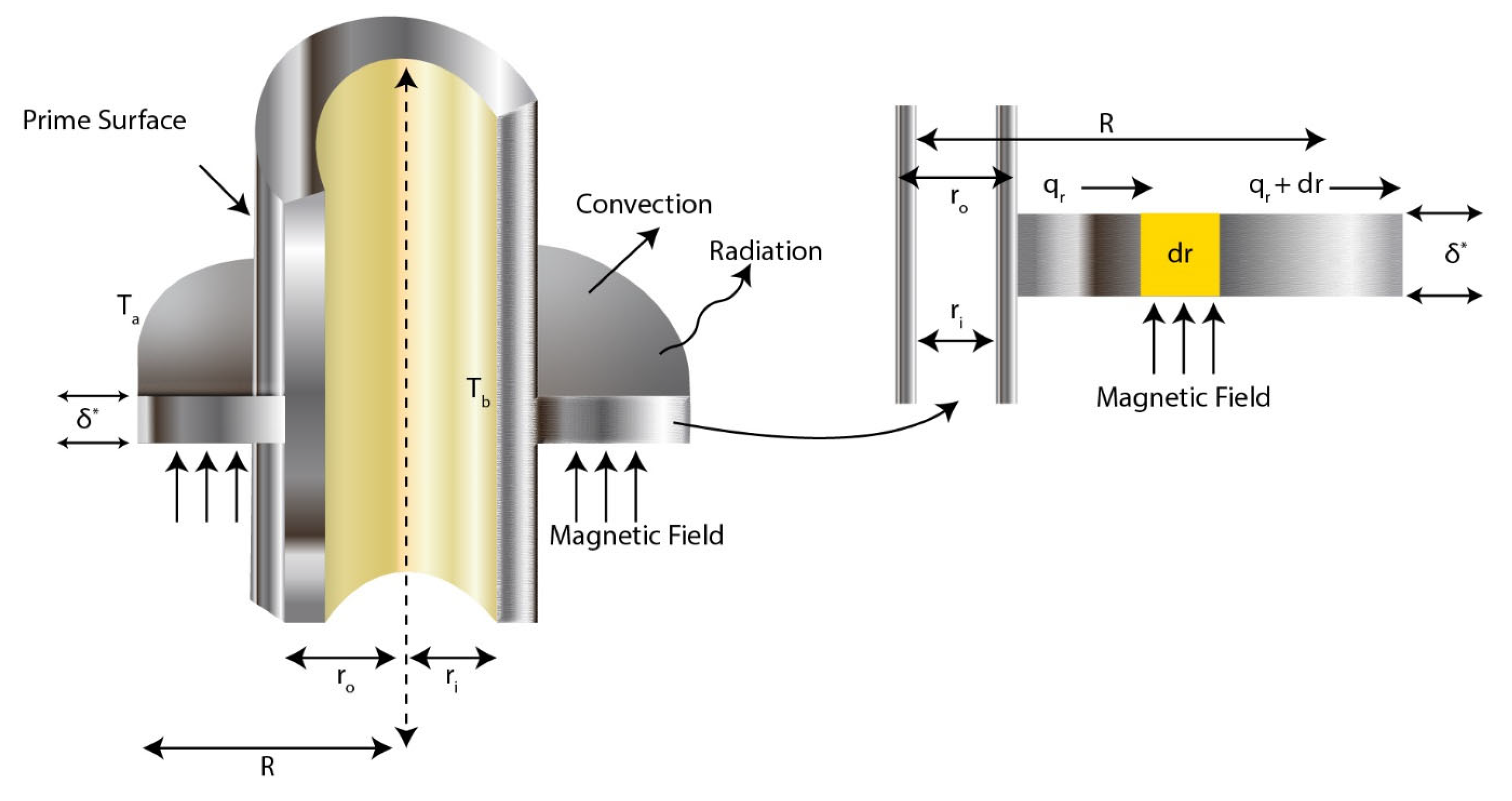
2. Problem Formulation

The problem under consideration assumes temperature-dependent Q in the fin, which is uniform, linear/non-linear. Moreover, the heat flow and temperature distribution in the fin are assumed to be time-independent, making the problem steady-state in nature. Furthermore, due to the thinness of the fin, the temperature dispersal is considered to be one-dimensional. Perpendicular to the radial surface, a consistent magnetic field has been applied. Figure 1 is a schematic representation of a primary surface with a thin, homogenous annular fin connected to it with thickness δ , area of cross-section A c r o s s , inner radius r i , the outer radius r 0 , and S p , which is the wet porous parameter considering references to Sowmya et al. [31]. The magnetic field intensity is given by
J c × J c σ t n f = σ t n f B 0 2 u 2
Gorla and Bakier [32] represent the rate of mass (m):
m = ρ V x w Δ x
Das and Ooi [33] have shown that the buoyant flow velocity, obtained from Darcy’s model:
V x = β g k υ T T a
In the absence of radiation, the conduction energy flow vector may be expressed as:
Q b a s e = Q c o n d + Q r a d
When utilizing Fourier’s law of conduction and neglecting radiation, the following expression can be derived
Q c o n d = A c k T d T d x
Linear and non-linear forms of q are considered as follows referring to Sobamowo et al. [34]
q = [ 1 + ( T T a ) ε g ] q a
q = q a [ 1 + ε g ( T T a ) + ε g 1 ( T T a ) 2 ]
The variable thermal is considered the form
k ( T ) = [ 1 + ( T T a ) λ ] k a
The incorporation of heat transfer coefficients, which are dependent on temperature, holds significant real implications, leading to various applications. Consequently, internal heat generation has been formulated, which is associated with temperature. By considering the aforementioned parameters in Equations (1)–(8), we can articulate the energy equation as follows:
d d r 2 π δ r k t n f T d T d r 2 π h b r T T a 2 π h a i f g r w w a + 2 π δ r q 2 π ε σ r T 4 T a 4 J c × J c σ t n f 2 π δ r T T a ρ f g β C p K w υ T T a 2 = 0
Boundary constraints of the model:
d T d r = 0 , r = r a n d T = T b , r = r 0
This study’s dimensionless parameters are
θ = T T b , θ a = T a T b , X = x L , C = δ t b , ε G = T b ε g , ε G 1 = T b ε g 1 , H = σ m B 0 2 u 2 r i 2 k a N r = r i 2 ε σ T b 3 k a δ , Q int = r i 2 q k a T b , N c c = r i 2 ρ f T b K g C p β k a 2 π δ r υ , S p = m 0 + m 1 , m 0 = h b r i 2 k a δ , m 1 = r i 2 h i f g b 2 k a δ C p f L e 2 / 3 , h = h a C p f L e 2 / 3 , w w a = b 2 T T a
Equation (9) can be transformed into its dimensionless form using Equations (10) and (11) and Table 1 as follows.
  • Temperature-dependent linear Q
    Z d 2 θ d η 2 + β ( θ θ a ) d 2 θ d η 2 + ( θ θ a ) β η + 1 d θ d η + 1 η + 1 d θ d η + β d θ d η 2 S p θ θ a Q int [ 1 + ε G ( θ θ a ) ] + N r θ 4 θ a 4 + Z 1 H θ θ a + N c c θ θ a 2 = 0
    Z = k 1 + 2 k f 2 ϕ 1 k f k 1 k 1 + 2 k f + ϕ 1 k f k 1 k 2 + 2 k n f 2 ϕ 2 k n f k 2 k 2 + 2 k n f + ϕ 2 k n f k 2 k 3 + 2 k h n f 2 ϕ 3 k h n f k 3 k 3 + 2 k h n f + ϕ 3 k h n f k 3 Z 1 = 1 + 3 σ 1 σ f 1 ϕ 1 σ 1 σ f + 2 σ 1 σ f 1 ϕ 1 1 + 3 σ 2 σ n f 1 ϕ 2 σ 2 σ n f + 2 σ 2 σ n f 1 ϕ 2 1 + 3 σ 3 σ h n f 1 ϕ 3 σ 3 σ h n f + 2 σ 3 σ h n f 1 ϕ 3
where
  • Temperature-dependent non-linear Q
Z d 2 θ d η 2 + β ( θ θ a ) d 2 θ d η 2 + ( θ θ a ) β η + 1 d θ d η + 1 η + 1 d θ d η + β d θ d η 2 S p θ θ a Q int [ 1 + ε G ( θ θ a ) + ε G 1 ( θ θ a ) 2 ] + N r θ 4 θ a 4 + Z 1 H θ θ a + N c c θ θ a 2 = 0
Boundary conditions in Equation (10) are transformed to
d θ 0 d η = 0 , θ R 1 = 0

3. Basic Concepts of DTM

If the function u x is infinitely continuously differentiable, it can be expressed as a Taylor series expansion. The Taylor series representation of u x is as follows:
u x = n = 0 1 n ! d n u x 0 d y n x x 0 n
The differential transform of a function u x of order n is denoted by U n . It is obtained by recursively applying the differential transform operator to the function u x   n times. The differential transform of order n is defined as follows:
U n = 1 n ! d n u x 0 d x n
For a given function U with respect to the transform variable x , the inverse differential transform is denoted by L 1 and is used to retrieve the original function u x . The inverse differential transform is mathematically expressed as:
u x = L 1 U = n = 0 U n x x 0 n
The Differential Transform Method (DTM) provides a systematic approach for transforming differential equations into algebraic equations using basic operators represented in Table 2 to transform functions and facilitate the solution of complex problems.

4. Analytical Procedure

  • The expression for temperature distribution with linear temperature-dependent Q after applying DTM properties:
    z d + 1 d + 2 Θ d + 2 + β c = 0 d Θ i d c + 1 d c + 2 Θ d c + 2 β θ a d + 1 d + 2 Θ d + 2 θ a β c = 0 d d c + 1 Θ d c + 1 1 + δ i 1 + β c = 0 d u = 0 c Θ c u d c + 1 Θ d c + 1 1 + δ u 1 + β c = 0 d d c + 1 Θ d c + 1 1 + δ i 1 + β c = 0 d c + 1 Θ c + 1 d c + 1 Θ d c + 1 N r c = 0 d u = 0 c v = 0 u Θ c Θ d c Θ c u Θ u v N r θ a 4 δ c Q int δ c + ε G Θ d ε G θ a δ c + Z 1 H Θ d Z 1 H θ a δ c + N c c c = 0 d Θ c d c + 2 θ a Θ d N c c θ a 2 δ c + S p Θ d S p θ a δ c = 0
  • The expression for temperature distribution with non-linear temperature-dependent Q after applying DTM properties:
    Z d + 1 d + 2 Θ d + 2 + β c = 0 d Θ c d c + 1 d c + 2 Θ d c + 2 β θ a d + 1 d + 2 Θ d + 2 θ a β c = 0 d d c + 1 Θ d c + 1 1 + δ c 1 + β c = 0 d u = 0 c Θ c u d c + 1 Θ d c + 1 1 + δ u 1 + β c = 0 d d c + 1 Θ d c + 1 1 + δ c 1 + β c = 0 d c + 1 Θ c + 1 d c + 1 Θ d c + 1 N r c = 0 d u = 0 c v = 0 u Θ c Θ d c Θ c u Θ u v N r θ a 4 δ c Q int δ c + ε G Θ k ε G θ a δ c + ε G 1 c = 0 d Θ c d c 2 θ a Θ d + θ a 2 δ c + Z 1 H Θ d Z 1 H θ a δ c + S p Θ d S p θ a δ c + N c c i = 0 d Θ c d c + 2 θ a Θ d N c c θ a 2 δ c = 0
Equation (14) is transformed to:
Θ 0 = a Θ 1 = 1
The terms of the series are obtained by utilizing the boundary constraints, and they are as follows
  • For linear Qint
Θ 2 a H Z 1 + a N r Q int + a S p + a Q int ϵ G + 2 a N c θ a H Z 1 θ a S p θ a Q int ϵ G θ a N c θ a 2 N r θ a 4 2 Z 1 + a β β θ a
Θ 3 a N c c + 3 a N r 2 Z β θ 2 2 a Z β θ 2 + 2 Z β θ a θ 2 6 Z 1 + a β β θ a
Θ 4 2 a N c c + 6 a N r Q int H Z 1 θ a S p θ a Q int ϵ G θ a N c c θ a 2 N r θ a 4 + H Z 1 θ 2 Z β θ 2 a Z β θ 2 + N r θ 2 + S p θ 2 + Q int ϵ G θ 2 + Z β θ a θ 2 + 2 N c c θ a θ 2 6 Z β θ 2 2 3 Z β θ 3 3 a Z β θ 3 + 3 Z β θ a θ 3 12 Z 1 + a β β θ a
Θ 5 6 a N c c + 20 a N r 4 Z β θ 2 4 a Z β θ 2 + 2 N c c θ 2 + 6 N r θ 2 + 4 Z β θ a θ 2 4 Z β θ 2 2 + 2 H Z 1 θ 3 3 Z β θ 3 3 a Z β θ 3 + 2 N r θ 3 + 2 S p θ 3 + 2 Q int ϵ G θ 3 + 3 Z β θ a θ 3 + 4 N c c θ a θ 3 40 Z β θ 2 θ 3 8 Z β θ 4 8 a Z β θ 4 + 8 Z β θ a θ 4 40 Z 1 + a β β θ a
  • For non-linear Qint
Θ 2 a H Z 1 + a N r Q int + a S p + a Q int ϵ G H Z 1 θ a + 2 a N c c θ a S p θ a Q int ϵ G θ a + 2 a Q int ϵ G 1 θ a N c c θ a 2 Q int ϵ G 1 θ a 2 N r θ a 4 2 Z 1 + a β β θ a
Θ 3 a N c c + 3 a N r a Q int ϵ G 1 2 Z β θ 2 2 a Z β θ 2 + 2 Z β θ a θ 2 6 Z 1 + a β β θ a
Θ 4 2 a N c c + 6 a N r Q int 2 a Q int ϵ G 1 H Z 1 θ a S p θ a Q int ϵ G θ a N c c θ a 2 Q int ϵ G 1 θ a 2 N r θ a 4 + H Z 1 θ 2 Z β θ 2 a Z β θ 2 + N r θ 2 + S p θ 2 + Q int ϵ G θ 2 + Z β θ a θ 2 + 2 N c c θ a θ 2 + 2 Q int ϵ G 1 θ a θ 2 6 Z β θ 2 2 3 Z β θ 3 3 a Z β θ 3 + 3 Z β θ a θ 3 12 Z 1 + a β β θ a
Θ 5 6 a N c c + 20 a N r 6 a Q int ϵ G 1 4 Z β θ 2 4 a Z β θ 2 + 2 N c c θ 2 + 6 N r θ 2 2 Q int ϵ G 1 θ 2 + 4 Z β θ a θ 2 4 Z β θ 2 2 + 2 H Z 1 θ 3 3 Z β θ 3 3 a Z β θ 3 + 2 N r θ 3 + 2 S p θ 3 + 2 Q int ϵ G θ 3 + 3 Z β θ a θ 3 + 4 N c c θ a θ 3 + 4 Q int ϵ G 1 θ a θ 3 40 Z β θ 2 θ 3 8 Z β θ 4 8 a Z β θ 4 + 8 Z β θ a θ 4 40 Z 1 + a β β θ a
After some further work, we obtain the following series describing the annular fin with a linear temperature-dependent internal heat source:
Θ X = a + a H Z 1 + a N r Q int + a S p + a Q int ϵ G + 2 a N c θ a H Z 1 θ a S p θ a Q int ϵ G θ a N c θ a 2 N r θ a 4 2 Z 1 + a β β θ a X 2 + a N c c + 3 a N r 2 Z β θ 2 2 a Z β θ 2 + 2 Z β θ a θ 2 6 Z 1 + a β β θ a X 3 + .............

5. Results and Discussion

The present study investigates the internal heat generation with linear and non-linear relationships to temperature and variable thermal conductivity of a ternary nanofluid in an annular fin. The DTM approximant was used to find analytical solutions for the reduced equations and their accompanying boundary conditions. When the acquired results are compared to prior work, they exactly match what is currently seen in Table 3.
For obtaining the most accurate results, we evaluated them considering the various values of dimensionless parameters to be θ a = 0.5 ,   S p = 0.3 ,   N r = 0.4 ,   N c c = 0.8 ,   H = 0.5 and Q = 0.8 , taking into account the thermo-physical properties of the fluid and base fluid, as listed in Table 4. In this study, we varied other factors to scrutinize their impact on the heat transfer of fins. To visualize and deliberate the variations in numerous non-dimensional factors on heat emission rates, we presented the results using appropriate graphs.
Figure 2a depicts the influence of temperature change on the wet porous parameter. An increase in the parameter representing the wet porous constraint coefficient has a cooling outcome on heat flow. When the wet porous parameter’s scale drops, the temperature upsurges. The porous structure of the fin facilitates the passage of fluid through it. As a result, the heat transmission rate increases.
Figure 2b illustrates the impact of linear and non-linear Q on the temperature profile variance of annular permeable fins. As the magnitude of Q increases, there is a noticeable improvement in temperature distribution. When the internal heat production of the fin rises, its mandate is to emit heat to the surrounding area, increasing the dimensionless temperature of the fin. From both Figure 2a,b, it is evident that non-linear temperature-dependent Q leads to a more significant amount of heat production related to the linear case.
Figure 3a demonstrates the consequence of Nr on heat transfer rate. As the value of Nr decreases, the heat transfer rate of the fin increases noticeably. The drastic temperature reduction inside the fin is evidence of heat loss to the surrounding liquid as a result of the increased radiation. The results imply that thermal energy transfer through radiation increases the rate of heat emission from the fin. The degree of heat transmission by radiation is determined by the temperature variance among the fin and its surroundings. Figure 3b shows how the convective sink temperature parameter improves the rate of heat transfer. As the variable is increased from 0.1 to 0.5, the temperature dispersion in the permeable fin rises dramatically. The processing time of the fin is influenced by various variables, including the ambient temperature. Higher ambient temperatures facilitate faster heat transfer into the surroundings, leading to a considerably shorter processing time for the fin.
Figure 4a illustrates the thermal behavior of the fin changes when β sways. For various values of β the thermal gradient, in this case, progressively diminishes. Additionally, as expected, a rise in value causes an increase in the thermal field. For all sloped values of β , the thermal field decreases. The effect of the magnetic parameter (Hartman number) on the thermal distribution is evident in Figure 4b. As the values of H increase, the heat decreases rapidly, leading to a significant upsurge in the heat transfer rate. This phenomenon is attributed to the suppression of convection as the values of H increase. The magnetic field hinders the motion of the fluid, reducing convection and, consequently, enhancing the rate of heat transfer.
The annular fin temperature profiles show the influence of N c c in Figure 5a. When the strength of convection increases, the cooling becomes more efficient, causing the material temperature to drop. As N c c (0.3, 0.4, 0.5) rises, the degree to which heat escapes from the fin decreases. Figure 5b illustrates the influence of nanoparticle shape on the rate of heat transfer. As the shape factor is increased, a noticeable rise in the temperature gradient can be observed. Lamina-shaped heat emission outperforms platelet-shaped and spherical emission, leading to a more significant enhancement in the rate of heat transfer. This indicates that the geometry of nanoparticles plays a crucial role in enhancing heat transfer efficiency, with lamina-shaped nanoparticles showing the most favorable heat transfer characteristics compared to platelet-shaped and spherical nanoparticles.

5.1. Nanoparticles Study

Table 5 presents the temperature profiles for three different types of nanofluids: n f , h n f and t n f Among these, t n f exhibits the highest values, indicating its superior heat-conducting abilities. Thermal conductivity plays a crucial role in determining the convective heat transfer coefficient, making it a key indicator in engineering applications. Therefore, for enhanced heat transfer performance, we recommend the use of a ternary nanofluid with superior thermal conductivity to achieve more efficient heat transfer in various engineering applications.

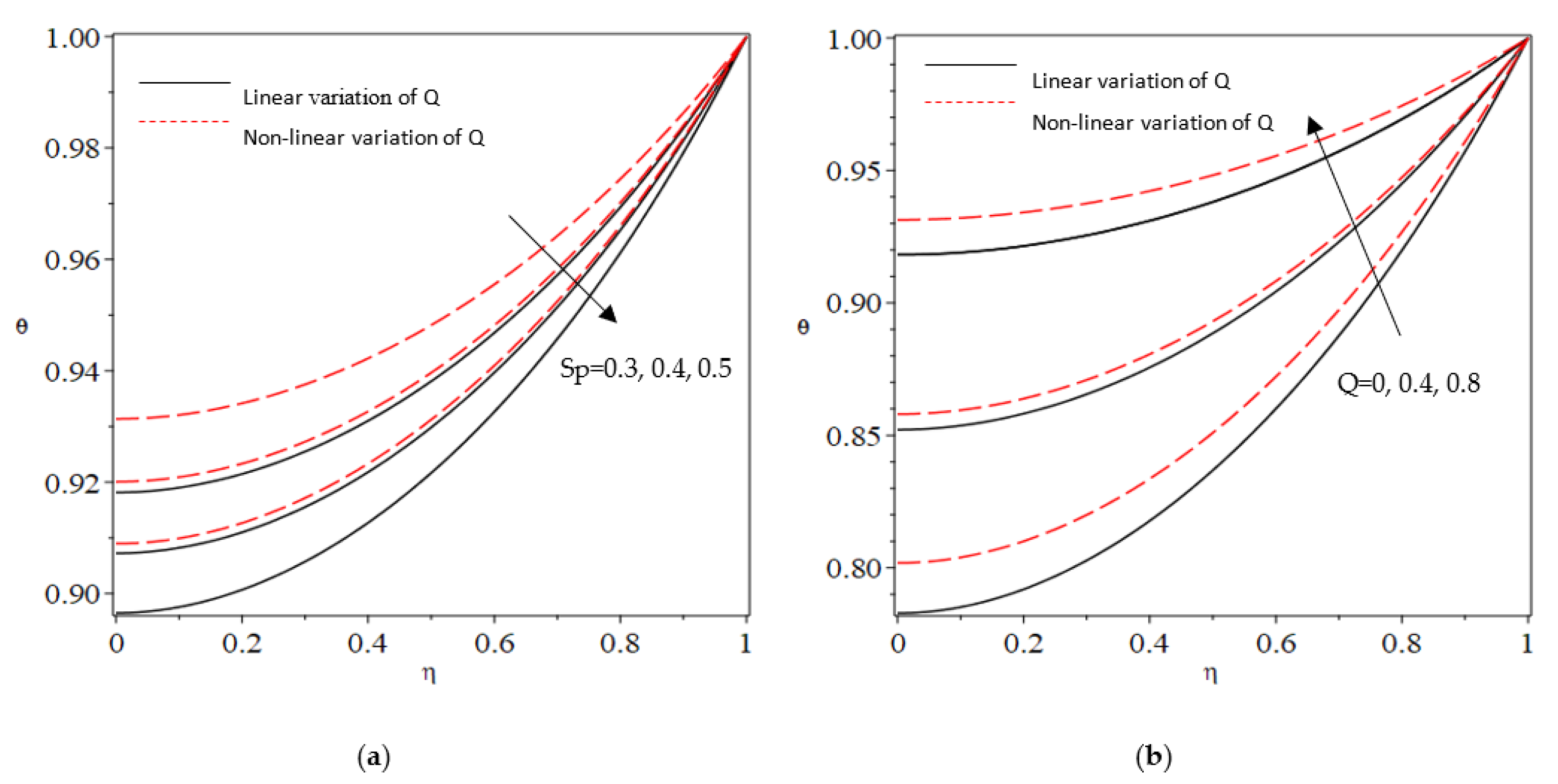
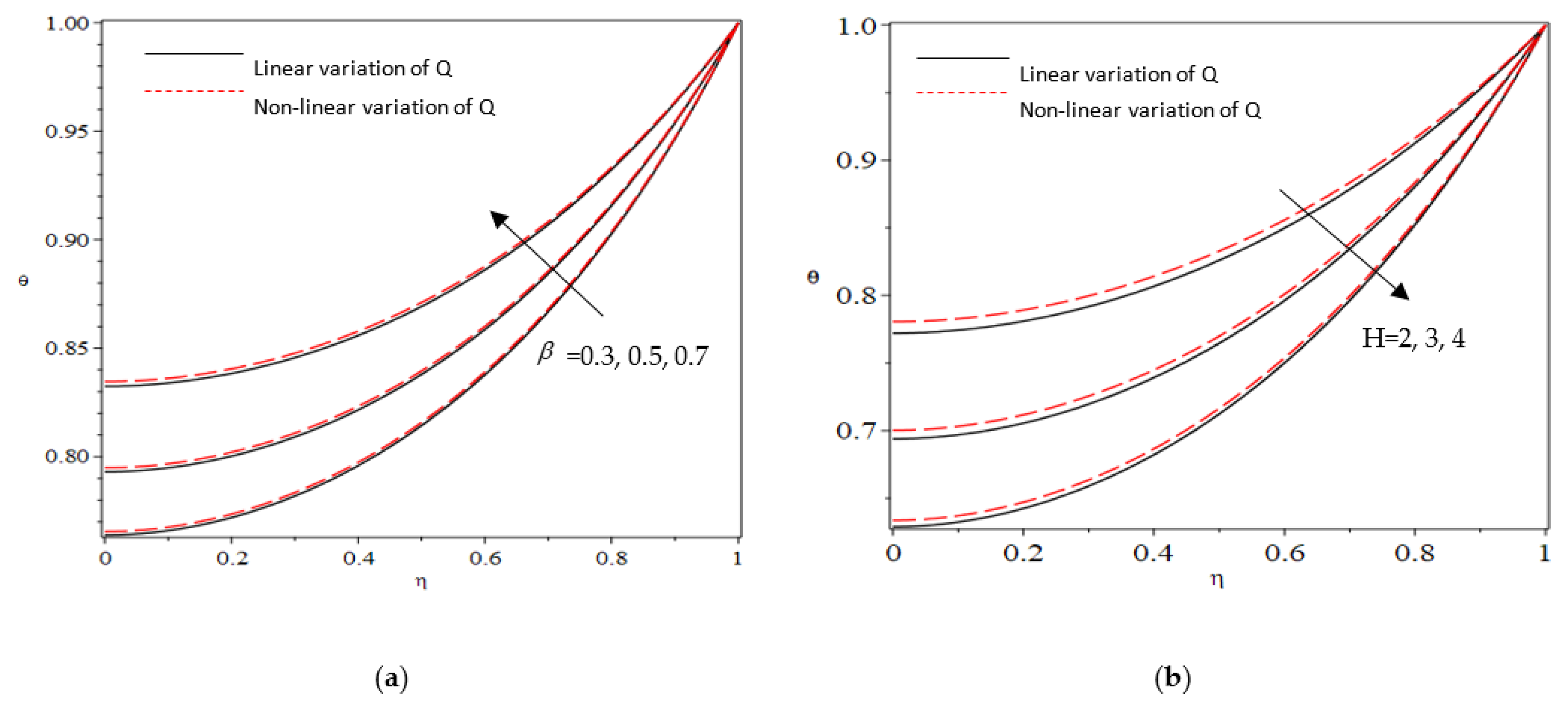
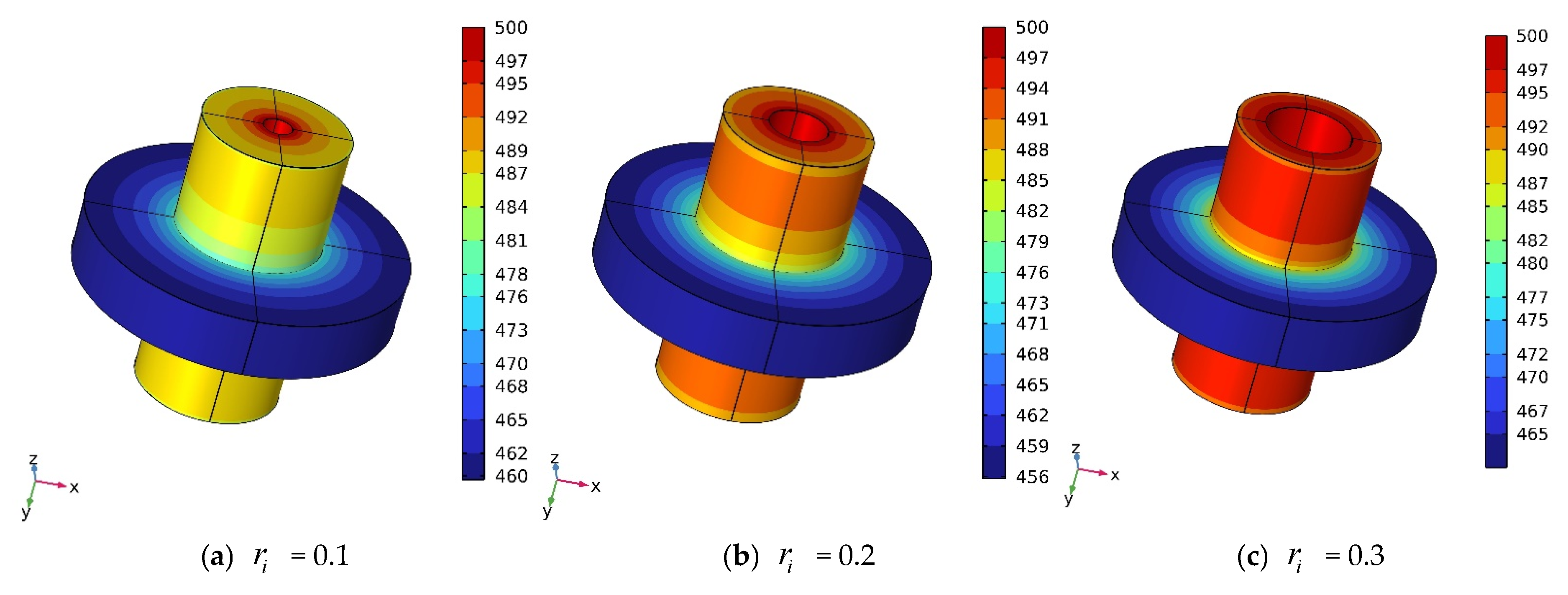
5.2. Thermal Analysis

Thermal analysis is a subfield of material science that investigates how material properties change with temperature. Various techniques are utilized, which differ based on the property being measured. Thermal analysis is critical in determining the impact of temperature on product functionality, as many materials have temperature-dependent properties. To assess the effect of stable thermal conditions on an annular fin, a steady-state thermal analysis based on the finite element technique is equipped in the current work. Magnesium alloy characteristics are used in the fin’s design. Calculating the heat transmission from the fin to the surroundings is the main goal of the analysis. In addition to the inlet and ambient temperatures being assumed to be 500 (K) and 293.15 (K), respectively, it is assumed that the heat transfer coefficient is 10.
Figure 6a–c demonstrates the significant influence of the inner radius on the heat transfer rate of annular fins. The inner radius was varied from 0.1 to 0.3 while maintaining a constant thickness of 0.3 for the rectangular profile. The results indicate that the fin with an inner radius of 0.1 can reduce the temperature from 500 K to 460 K, while the fin with an inner radius of 0.2, can dissipate the maximum temperature and decrease it to 456 K. However, further increments in the inner radius reduce the rate of heat emission. Therefore, it can be decided that an inner radius of 0.2 is ideal for achieving a higher rate of heat transmission.
Figure 7a–c depict how the thickness of annular fins affects the rate of heat transfer. The thickness was varied from 0.1 to 0.3 while maintaining a constant inner radius of 0.2 for the rectangular profile. Figure 7a shows the results for a heat supply of 500 K and a thickness of 0.1, where the fin temperature was reduced to 429 K. For thicknesses of 0.2 and 0.3, the temperature drops to 447 K and 454 K, respectively. However, further increases in thickness lead to a decrease in the heat emission rate. Therefore, it can be determined that a thickness of 0.1 is optimal for achieving a higher rate of heat transmission.

6. Conclusions

The primary focus of this study is to examine the heat transfer characteristics of a permeable annular fin immersed in a ternary nanofluid. The investigation involves studying the effects of linear and non-linear variations in the internal heat generation (Q) on the fin’s heat transfer performance. To achieve this, we utilize the Differential Transform Method (DTM) to obtain a solution for the dimensional heat equation governing the heat transfer in the fin. By employing DTM, we can effectively analyze and understand the heat distribution of the annular fin in the presence of the ternary nanofluid.
  • The heat distribution of the fin can be enhanced by incrementing the values of variable thermal conductivity;
  • Non-linear variation in the internal heat source parameter elevated the thermal intensity inside the fin;
  • The enhancement of the heat transfer rate is achieved by increasing both the radiative and wet porous parameters. This improvement can be attributed to the combined effects of thermal radiation and the presence of moisture in the vicinity of the fin surface;
  • The thickness and inner radius of a fin are crucial factors that impact the heat transmission rate. Based on the analysis, it can be concluded that a cost-effective annular rectangular fin can be achieved by maintaining a thickness of 0.1 and an inner radius of 0.2.

Author Contributions

Conceptualization, A.S. and P.V.A.S.; Data curation, P.V.A.S. and S.V.K.V.; Formal analysis, P.S.; Funding Acquisition, N.A.S.; Methodology, P.S., P.V.A.S. and J.S.C.; Software, B.N.H.; Validation, B.N.H. and S.A.; Writing—original draft, P.V.A.S.; Writing—review and editing, N.A.S., S.V.K.V. and B.N.H. All authors have read and agreed to the published version of the manuscript.

Funding

This project was supported by Researchers Supporting Project number (RSPD2023R909), King Saud University, Riyadh, Saudi Arabia.

Data Availability Statement

All the data are present in this article.

Acknowledgments

This project was supported by Researchers Supporting Project number (RSPD2023R909), King Saud University, Riyadh, Saudi Arabia.

Conflicts of Interest

The authors declare no conflict of interest.

Nomenclature

S p wet porous parameter
N c convective-conductive parameter
h heat transfer coefficient Wm 2 K 1
Q heat generation number
χ aspect ration
C p specific heat Jkg 1 K 1
w width of the fin m
T temperature K
ε T emissivity
L length m
ρ density kgm 3
g acceleration due to gravity ms 2
H Hartman number
K Permeability m 2
ρ density kgm 3
ε surface emissivity of fin
θ non-dimensional temperature
N r radiative parameter
A b cross-sectional area m 2
σ Stefan-Boltzmann constant Wm 2 K 4
k thermal conductivity Wm 1 K 1
t b fin thickness m
B surface emissivity parameter
m mass flow rate kgs 1
J c current intensity A
ω fin effectiveness
m 0 , m 1 constants and m 2 = m 0 + m 1
b 2 variable parameter K 1
h a heat transfer coefficient at temperature T a
θ a dimensionless ambient temperature
i g f latent heat of water evaporation J k g 1

References

  1. Hosseinzadeh, K.; Roghani, S.; Mogharrebi, A.; Asadi, A.; Waqas, M.; Ganji, D. Investigation of cross-fluid flow containing motile gyrotactic microorganisms and nanoparticles over a three-dimensional cylinder. Alex. Eng. J. 2020, 59, 3297–3307. [Google Scholar] [CrossRef]
  2. Hayat, T.; Riaz, R.; Aziz, A.; Alsaedi, A. Influence of Arrhenius activation energy in MHD flow of third grade nanofluid over a nonlinear stretching surface with convective heat and mass conditions. Phys. A Stat. Mech. Its Appl. 2020, 549, 124006. [Google Scholar] [CrossRef]
  3. Koriko, O.K.; Adegbie, K.S.; Shah, N.A.; Animasaun, I.L.; Olotu, M.A. Numerical solutions of the partial differential equations for investigating the significance ofpartial slip due to lateral velocity and viscous dissipation: The case of blood-gold Carreaunanofluid and dusty fluid. Numer. Methods Partial. Differ. Equ. 2021, 1–29. [Google Scholar] [CrossRef]
  4. Lou, Q.; Ali, B.; Rehman, S.U.; Habib, D.; Abdal, S.; Shah, N.A.; Chung, J.D. Micropolar Dusty Fluid: Coriolis Force Effects on Dynamics of MHD Rotating Fluid When Lorentz Force Is Significant. Mathematics 2022, 10, 2630. [Google Scholar] [CrossRef]
  5. Salehi, S.; Nori, A.; Hosseinzadeh, K.; Ganji, D. Hydrothermal analysis of MHD squeezing mixture fluid suspended by hybrid nanoparticles between two parallel plates. Case Stud. Therm. Eng. 2020, 21, 100650. [Google Scholar] [CrossRef]
  6. Ramesh, G.K.; Madhukesh, J.K.; Shah, N.A.; Yook, S.-J. Flow of hybrid CNTs past a rotating sphere subjected to thermal radiation and thermophoretic particle deposition. Alex. Eng. J. 2023, 64, 969–979. [Google Scholar] [CrossRef]
  7. Ullah, I.; Ullah, S.; Ali, A.; Shah, S.I.; Weera, W.; Alam, M.M. Heat transfer analysis from moving convection-radiative triangular porous fin exposed to heat generation. Case Stud. Therm. Eng. 2022, 38, 102177. [Google Scholar] [CrossRef]
  8. Gouran, S.; Ghasemi, S.; Mohsenian, S. Effect of internal heat source and non-independent thermal properties on a convective–radiative longitudinal fin. Alex. Eng. J. 2022, 61, 8545–8554. [Google Scholar] [CrossRef]
  9. Kumar, R.S.V.; Kumar, R.N.; Sowmya, G.; Prasannakumara, B.C.; Sarris, I.E. Exploration of Temperature Distribution through a Longitudinal Rectangular Fin with Linear and Exponential Temperature-Dependent Thermal Conductivity Using DTM-Pade Approximant. Symmetry 2022, 14, 690. [Google Scholar] [CrossRef]
  10. Subray, P.V.A.; Hanumagowda, B.N.; Varma, S.V.K.; Zidan, A.M.; Alaoui, M.K.; Raju, C.S.K.; Shah, N.A.; Junsawang, P. Dynamics of Heat Transfer Analysis of Convective-Radiative Fins with Variable Thermal Conductivity and Heat Generation: Differential Transformation Method. Mathematics 2022, 10, 3814. [Google Scholar] [CrossRef]
  11. Lee, H.-L.; Yang, Y.-C.; Chu, S.-S. Transient thermoelastic analysis of an annular fin with coupling effect and variable heat transfer coefficient. J. Therm. Stress. 2002, 25, 1105–1120. [Google Scholar] [CrossRef]
  12. Ganji, D.; Ganji, Z. Determination of temperature distribution for annular fins with temperature dependent thermal conductivity by HPM. Therm. Sci. 2011, 15, 111–115. [Google Scholar] [CrossRef]
  13. Mallick, A.; Prasad, D.K.; Behera, P.P. Stresses in radiative annular fin under thermal loading and its inverse modeling using sine cosine algorithm (SCA). J. Therm. Stress. 2018, 42, 401–415. [Google Scholar] [CrossRef]
  14. Arslanturk, C. Correlation equations for optimum design of annular fins with temperature dependent thermal conductivity. Heat Mass Transf. 2008, 45, 519–525. [Google Scholar] [CrossRef]
  15. Das, R. Identification of materials in a hyperbolic annular fin for a given temperature requirement. Inverse Probl. Sci. Eng. 2015, 24, 213–233. [Google Scholar] [CrossRef]
  16. Sowmya, G.; Gamaoun, F.; Abdulrahman, A.; Kumar, R.S.V.; Prasannakumara, B.C. Significance of thermal stress in a convective-radiative annular fin with magnetic field and heat generation: Application of DTM and MRPSM. Propuls. Power Res. 2022, 11, 527–543. [Google Scholar] [CrossRef]
  17. Mallick, A.; Das, R. Application of Simplex Search Method for Predicting Unknown Parameters in an Annular Fin Subjected to Thermal Stresses. J. Therm. Stress. 2013, 37, 236–251. [Google Scholar] [CrossRef]
  18. Ranjan, R.; Mallick, A.; Prasad, D.K. Closed form solution for a conductive–convective–radiative annular fin with multiple nonlinearities and its inverse analysis. Heat Mass Transf. 2016, 53, 1037–1049. [Google Scholar] [CrossRef]
  19. Sarwe, D.U.; Kulkarni, V.S. Differential transformation method to determine heat transfer in annular fins. Heat Transf. 2021, 50, 7949–7971. [Google Scholar] [CrossRef]
  20. Kundu, B. Exact Method for Annular Disc Fins with Heat Generation and Nonlinear Heating. J. Thermophys. Heat Transf. 2017, 31, 337–345. [Google Scholar] [CrossRef]
  21. Reddy, N.K.; Swamy, H.K.; Sankar, M.; Jang, B. MHD convective flow of Ag–TiO2 hybrid nanofluid in an inclined porous annulus with internal heat generation. Case Stud. Therm. Eng. 2023, 42, 102719. [Google Scholar] [CrossRef]
  22. Al-Mdallal, Q.M.; Kanimozhi, B.; Muthtamilselvan, M.; Abdalla, B. Combined Marangoni and Buoyancy Convection in a Porous Annular Cavity Filled with Ag-MgO/Water Hybrid Nanofluid. Curr. Nanosci. 2023, 19, 4–14. [Google Scholar] [CrossRef]
  23. Kundu, B.; Lee, K.-S. A proper analytical analysis of annular step porous fins for determining maximum heat transfer. Energy Convers. Manag. 2016, 110, 469–480. [Google Scholar] [CrossRef]
  24. Kundu, B.; Lee, K.-S. Analytical tools for calculating the maximum heat transfer of annular stepped fins with internal heat generation and radiation effects. Energy 2014, 76, 733–748. [Google Scholar] [CrossRef]
  25. Rostami, A.K.; Ganji, D.D. Optimization of a shell and helically finned tube heat exchanger with stepped annular fins. ZAMM Z. Fur Angew. Math. Und Mech. 2023, 103, e202200310. [Google Scholar] [CrossRef]
  26. Sanchouli, M.; Payan, S.; Payan, A.; Nada, S. Investigation of the enhancing thermal performance of phase change material in a double-tube heat exchanger using grid annular fins. Case Stud. Therm. Eng. 2022, 34, 101986. [Google Scholar] [CrossRef]
  27. Chen, H.-T.; Chiu, Y.-J.; Liu, C.-S.; Chang, J.-R. Numerical and experimental study of natural convection heat transfer characteristics for vertical annular finned tube heat exchanger. Int. J. Heat Mass Transf. 2017, 109, 378–392. [Google Scholar] [CrossRef]
  28. Nagarani, N.; Mayilsamy, K. Experimental heat transfer analysis on Annular Circular and Elliptical fins. Int. J. Eng. Sci. Technol. 2010, 2, 2839–2845. [Google Scholar]
  29. Kang, H.S.; Look, D.C. Optimization of a trapezoidal profile annular fin. Heat Transf. Eng. 2009, 30, 359–367. [Google Scholar] [CrossRef]
  30. Galgat, S.S.; Jadhav, N.P. Experimental Investigation of Heat Transfer Enhancement by Vortex Generators in Heat Ex-changer. Int. Eng. Res. J. 2015, 2, 5290–5294. [Google Scholar]
  31. Sowmya, G.; Gireesha, B.J.; Prasannakumara, B.C. Scrutinization of different shaped nanoparticle of molybdenum disulfide suspended nanofluid flow over a radial porous fin. Int. J. Numer. Methods Heat Fluid Flow 2019, 30, 3685–3699. [Google Scholar] [CrossRef]
  32. Gorla, R.S.R.; Bakier, A. Thermal analysis of natural convection and radiation in porous fins. Int. Commun. Heat Mass Transf. 2011, 38, 638–645. [Google Scholar] [CrossRef]
  33. Das, R.; Ooi, K. Predicting multiple combination of parameters for designing a porous fin subjected to a given temperature requirement. Energy Convers. Manag. 2013, 66, 211–219. [Google Scholar] [CrossRef]
  34. Sobamowo, M.G.; Jayesimi, L.O.; Waheed, M.A. Effects of Internal Heat Generation on the Thermal Stability of a Porous Fin. World Sci. News 2020, 149, 110–127. [Google Scholar]
  35. Hayat, T.; Nadeem, S. Heat transfer enhancement with Ag–CuO/water hybrid nanofluid. Results Phys. 2017, 7, 2317–2324. [Google Scholar] [CrossRef]
  36. Mallick, A.; Ghosal, S.; Sarkar, P.K.; Ranjan, R. Homotopy Perturbation Method for Thermal Stresses in an Annular Fin with Variable Thermal Conductivity. J. Therm. Stress. 2014, 38, 110–132. [Google Scholar] [CrossRef]
Figure 1. Physical model of the problem.
Energies 16 06155 g001
Figure 2. Variation in (a) S p and (b) Q on θ versus η .
Energies 16 06155 g002
Figure 3. Variation in (a) Nr and (b) θ a on θ versus η .
Energies 16 06155 g003
Figure 4. Variation in (a) β and (b) H on θ versus η .
Energies 16 06155 g004
Figure 5. Variation in (a) N c c and (b) q on θ versus η .
Energies 16 06155 g005
Figure 6. Effect of the variable inner radius r i by keeping δ = 0.3 .
Energies 16 06155 g006
Figure 7. Effect of variable thickness δ by keeping r i = 0.2 .
Energies 16 06155 g007
Table 1. Thermophysical properties (considered from Hayat, and Nadeem [35]).
PropertiesExpressions for Ternary Nanofluid Properties
Dynamic viscosity μ t n f = μ f 1 1 ϕ 1 2.5 1 ϕ 2 2.5 1 ϕ 3 2.5
Thermal conductivity k t n f = k h n f k 3 + 2 k h n f 2 ϕ 3 k h n f k 3 k 3 + 2 k h n f + ϕ 3 k h n f k 3
where k h n f = k n f k 2 + 2 k n f 2 k n f k 2 ϕ 2 k 2 + 2 k n f + k n f k 2 ϕ 2 , k n f = k f k 1 + 2 k f 2 k f k 1 ϕ 1 k 1 + 2 k f + k f k 1 ϕ 1
Heat capacity ρ C p t n f = ϕ 1 ρ C p 1 ρ C p f + 1 ϕ 1 1 ϕ 2 1 ϕ 3 + ϕ 3 ρ C p 3 ρ C p f + ϕ 2 ρ C p 2 ρ C p f
Thermal expansion ρ β t n f = ϕ 1 ρ β 1 ρ β f + 1 ϕ 1 1 ϕ 2 1 ϕ 3 + ϕ 3 ρ β 3 ρ β f + ϕ 2 ρ β 2 ρ β f
Electrical conductivity σ t n f = σ h n f 1 + 3 σ 3 σ h n f 1 ϕ 3 σ 3 σ h n f + 2 σ 3 σ h n f 1 ϕ 3 where
σ h n f = σ n f 1 + 3 σ 2 σ n f 1 ϕ 2 σ 2 σ n f + 2 σ 2 σ n f 1 ϕ 2 , σ n f = σ f 1 + 3 σ 1 σ f 1 ϕ 1 σ 1 σ f + 2 σ 1 σ f 1 ϕ 1
Table 2. Properties of DTM.
Basic FunctionTransfigured Function
z x = u x ± v x Z n = U n ± V n
z x = α u x Z n = α U n
z x = d u x d x Z n = n + 1 U n + 1
z x = d 2 u x d x 2 Z n = n + 1 n + 2 U n + 2
z x = d m u x d x m Z n = n + 1 n + 2 ........ n + m U n + m
z x = u x v x Z n = m = 0 n U m V n m
z x = α x m Z n = α δ n m ; where δ n m = 1 , i f m = m 0 , i f n m
Table 3. Comparison of non-dimensional temperature distribution with existing work.
Non-Dimensional RadiusArslanturk [14]
(FDM)
Mallick et al. [36]
(HPM)
Present Study
(DTM)
01.0001.0001.0000
0.10.94770.94550.9497
0.20.90360.90130.9054
0.30.86680.86590.8669
0.40.83650.83800.8341
0.50.81190.81650.8067
0.60.79270.80050.7849
0.70.77820.78910.7684
0.80.76820.78160.7574
0.90.76240.77750.7517
10.76050.77630.7514
Table 4. Thermo-physical properties.
Physical Properties ρ ( k g / m 3 ) C p ( J / K g K ) k ( W / m K ) σ ( S / m )
H 2 O 997.141790.6130.05
Graphene Oxide G O 36007653000 1.033 × 10 4
Cobalt8900420100 1.602 × 10 7
Cu8933675401 5.96 × 10 7
Table 5. Assessment with n f , h n f , and t n f .
X Nanofluid
1 0 1
Hybrid Nanofluid
1 0 1
Ternary Nanofluid
1 0 1
θ X
08.6458.6488.686
0.1258.6608.6708.707
0.2508.7338.7348.769
0.3758.8318.8368.869
0.5008.9758.9799.009
0.6259.1619.1639.188
0.7509.3919.3929.409
0.8759.6639.6689.678
1111
Disclaimer/Publisher’s Note: The statements, opinions and data contained in all publications are solely those of the individual author(s) and contributor(s) and not of MDPI and/or the editor(s). MDPI and/or the editor(s) disclaim responsibility for any injury to people or property resulting from any ideas, methods, instructions or products referred to in the content.

