
Heat Storage for Cooking: A Discussion on Requirements and Concepts
Department of Energy and Process Engineering, Norwegian University of Science and Technology, 7034 Trondheim, Norway
Energies 2023, 16(18), 6623; https://doi.org/10.3390/en16186623
Submission received: 21 June 2023
/
Revised: 21 August 2023
/
Accepted: 1 September 2023
/
Published: 14 September 2023
(This article belongs to the Special Issue Small Scale Solar Thermal Energy Storage Systems for Rural Energy)
Abstract
:Methodologies for direct and indirect solar energy for cooking are discussed. Clean and renewable energy solutions for cooking are, in particular, in demand in the sub-Saharan region where fuel wood is the main source of energy for a large part of the population, in particular in off-grid communities. As solar radiation is intermittent, energy storage solutions are required to provide cooking power during off-sun hours. Electrical batteries can be feasible for low-power applications (lights, electronics, and chargers) but tend to be costly and short-lived solutions for high-power cooking requirements. Heat battery concepts are discussed here together with prototype examples of latent and sensible heat storage solutions which have been laboratory tested for cooking and frying. Simplified computational comparisons between latent and sensible heat storage options show that oil and rock bed sensible heat systems, with a natural convection heat transfer, can be designed to provide variable cooking power levels. Oversized sensible heat storage systems can approach the near constant temperature and heat storage properties of a latent heat system. Latent heat storage systems can be more suitable for frying than for cooking applications.
1. Background
The need for clean and sustainable energy solutions for cooking in regions where biomass is the dominant fuel is well-documented, and it is high on the priority list of actions for change of several humanitarian-based agencies and organizations. There are also quite a few organizations and web resources promoting clean cooking technologies (see a list of some web resources after the Acknowledgements section below).
The bulk of the work profiled by the different organizations concerns fuel-based direct cookers. The objectives of improving cookers are then to use less fuel (more energy efficient cookers) or different fuel types and to avoid health hazards associated with in-door, open-fire solutions (clean cookers). The term “clean cooking” sometimes also refers to the replacement of biomass (fire wood or charcoal) with LPG or to the use of electrical cookers instead of combustion cookers.
Grid-connected users can make use of modern electric cooking stoves, as long as the power supply is stable and affordable. The challenge arises for off-grid cooking, or for cases where the grid is unreliable or where load shedding is enforced.
Direct solar cookers, where the cooking pot is directly heated by the sun’s rays, have been available in many forms for a long time( see a couple of reviews by [1,2] as well as other similar ones). A wealth of information can also be found on the internet; Solar Cookers International (https://www.solarcookers.org, accessed on 20 July 2023) particularly specializes in the technology of direct solar cookers. Typical options are funnel cookers, box-type cookers, panel cookers, and concentrating cookers (e.g., parabolic dish/trough geometries). There may be social and cultural reasons why these solutions have not found wide-spread use, but being restricted to cooking only during sunshine hours is one limiting factor.
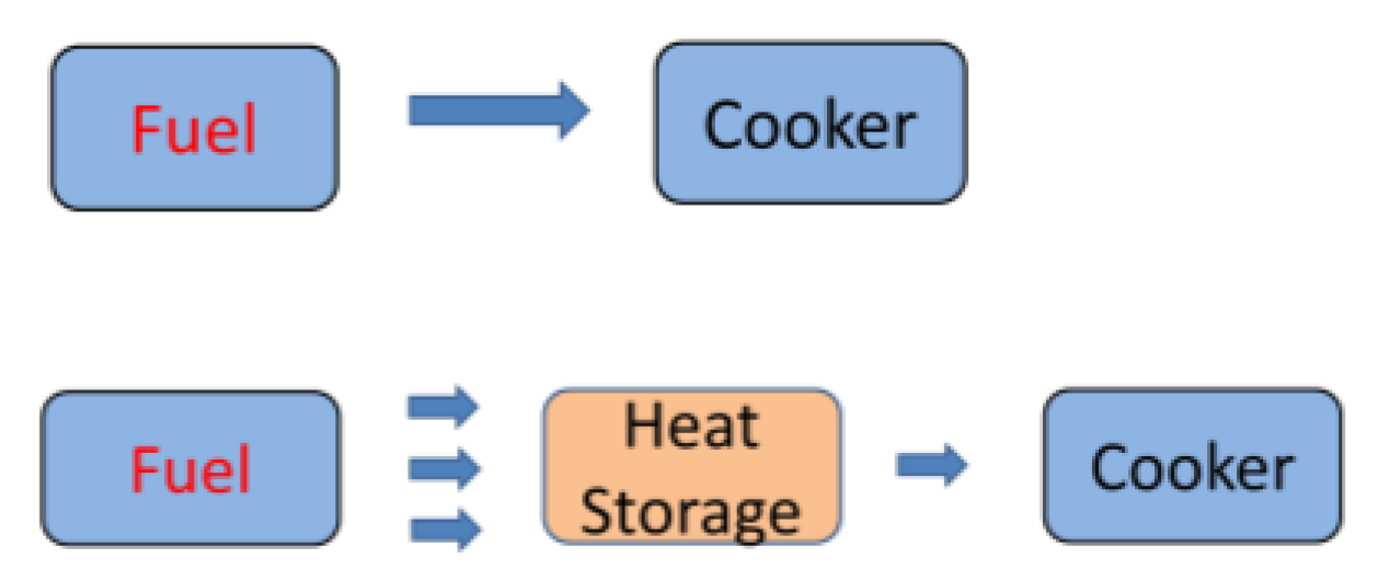
The case for consideration here is cooking technology based on energy storage concepts, as illustrated in Figure 1. This gives a shift in technological focus as cooking systems then can provide fuel flexibility. Different heating methods can charge a heat storage unit which then powers the cooker at times when needed. The use of the term “fuel” can then be generalized to include all power sources available: solar radiation, different electrical generators (wind, hydro, and PV) as well as combustion-based sources (biomass and LPG). The motivation for a storage-based cooking technology can be wider than the motivation for clean cooking and energy efficiency, as now the aim can also be to avoid the use of fire wood, charcoal, and LPG altogether as energy sources for cooking.
Energy storage for cooking can be available in the form of electrical batteries or as Thermal Energy Storage units (TESs).
Electrical batteries can be feasible for small-scale solutions, as the energy requirements for cooking small amounts of food is low and as the power requirements can be made modest by insulating the cooking pot well. But batteries do remain the weak point in off-grid solutions, as they are costly components which also have limited lifetimes. However, as battery technology is developing and batteries become economically feasible components also in high-power systems, the future for off-grid cooking solutions may well be with electrical batteries [3].
The current state of TESs for cooking is essentially that solutions are not available on the market. One reason may be that it is challenging to develop solutions which are affordable, technically safe and reliable, have acceptable cooking power, are easy to use with controllable power, and do not require frequent maintenance or large spaces. Such requirements are particularly challenging to fulfil in off-grid, sub-Saharan rural environments.
A general review of thermal energy storage systems for a large range of applications is given by [4]. Heat storage systems for cookers are often based on latent heat systems with Phase Change Materials (PCMs). Reviews are provided by [5,6,7], where PCMs are introduced for both direct cookers and for Solar Concentrating systems (SCs). Heat storage cooker concepts have been demonstrated to work in laboratory environments, but successful implementations in society are still lacking. The significance of cultural and social barriers for the acceptance of new technology is also discussed in the review of [8].
As the cost of Photo Voltaic solar panels (PVs) have been steadily decreasing, PV-to-heat can now be a competitive economic option for solar heating systems. PV systems are less energy efficient (less useful energy harvest per area of solar radiation) than direct heat collectors. However, PV systems are mechanically simpler systems and less challenging to produce, install, and maintain.
Some challenges related to the development of heat storage solutions for cooking are discussed here, including the aspects of energy conversion, heat transfer, and storage options. Along with the discussion, some design requirements are suggested and are summarized towards the end in a comparison of some examples of prototype systems which have been constructed and tested in the laboratory setting. Some aspects of the storage systems and the heat transfer methods are also illustrated computationally, using simplified models of selected base cases. The purpose of the cases is to illustrate the differences between the concepts and not to provide accurate computational results for design purposes. The heat transfer coefficients are, in particular, chosen for illustrational purposes and can vary strongly according to the actual geometry and external conditions. The material properties applied in the cases are listed in Table 1.
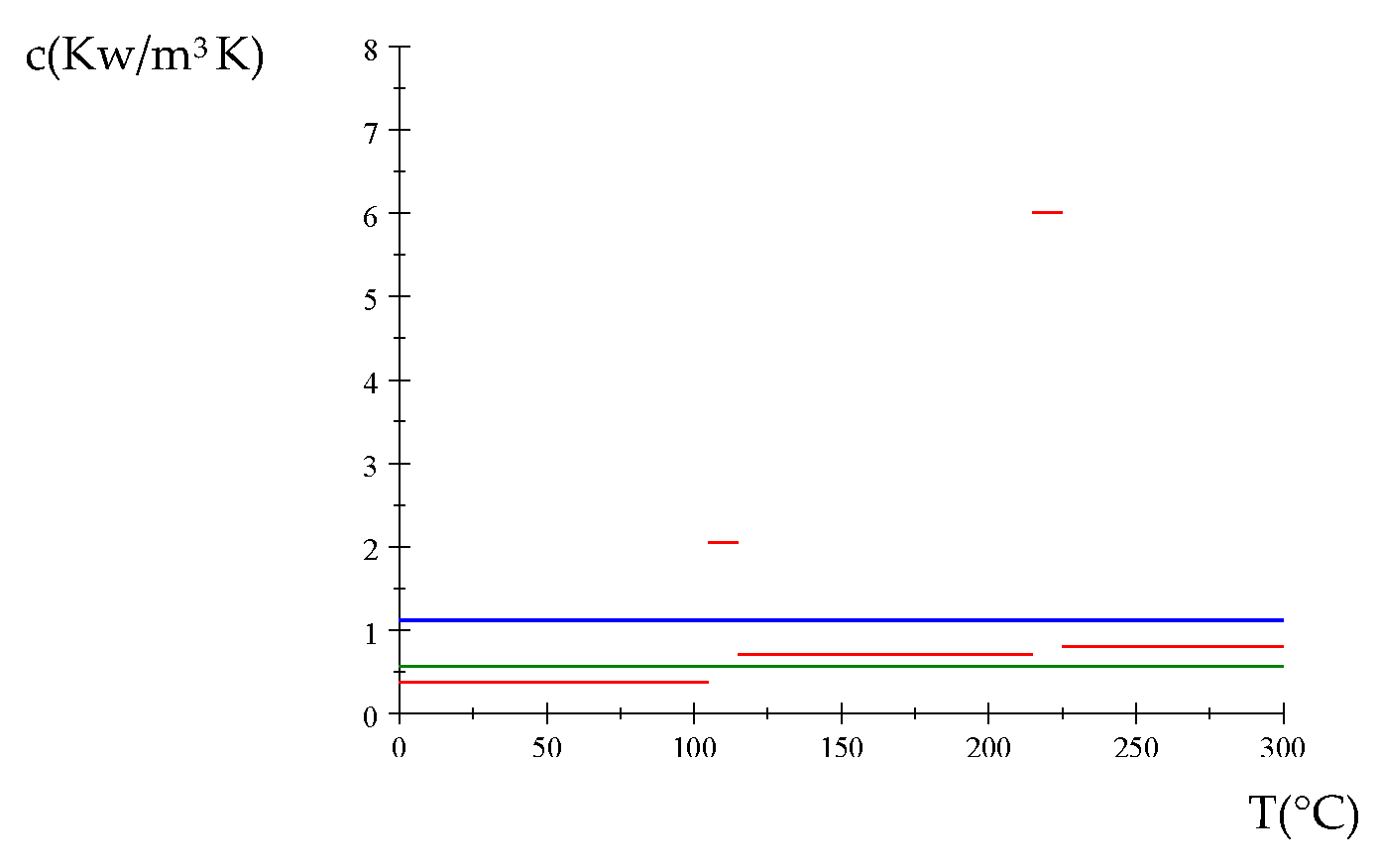
The 40–60% NaNO3-KNO3 mixture is used in the form of molten salt for heat transfers in solar thermal power plants and is often termed “Solar Salt”. The latent heat can be represented as an apparent heat capacity, and the following piecewise constant values were experimentally derived [9]:
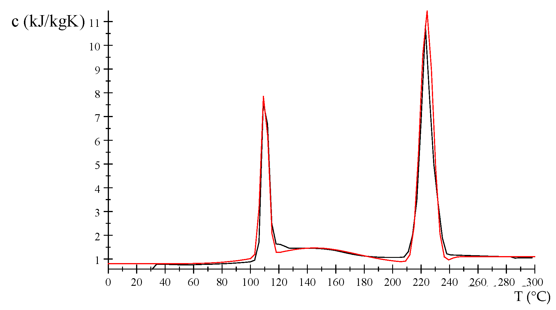
The measured apparent heat capacities for Solar Salt from [9] were fitted here to three Gaussians and a Heaviside function for use in the simplified model-based comparisons of sensible and latent heat systems. The result of the heat capacity function for solar salt is
with the following parameter values: s1 = 2.5, T1 = 110, s2 = 4.5, T2 = 224, s3 = 30, and T3 = 145. T is the temperature in degrees °C.
The measured data [9] and the curve fitted function are shown in Figure 2. The measured heat capacities for Solar Salt (black, data from [9]) and the curve fitted to Gaussian functions (red, Equation (2)) are in Figure 2.
As a starting point for all the systems, the requirements in Table 2 can be suggested:
1.1. Energy and Power for Cooking
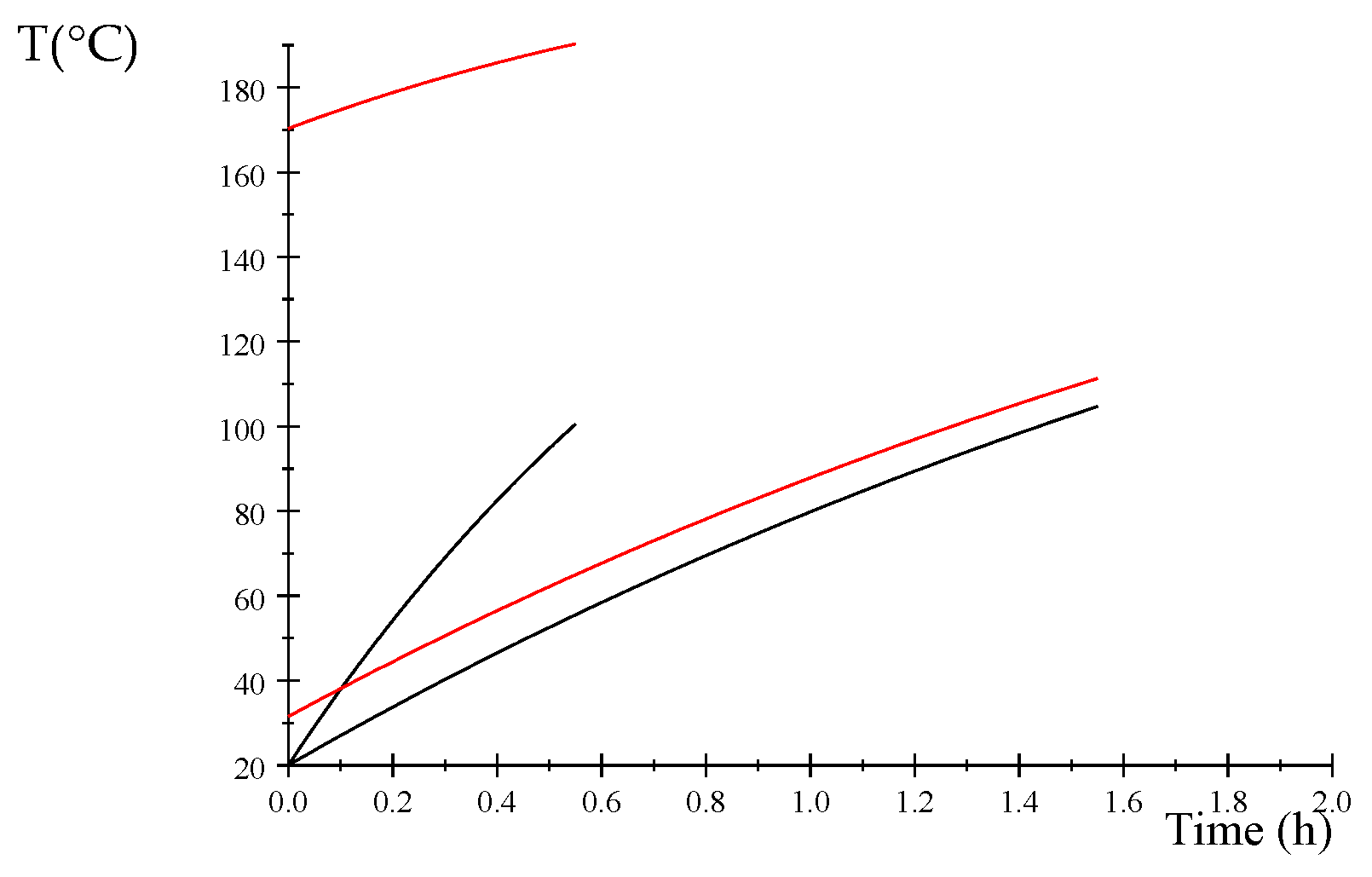
The cooking of food will typically require heating of the water to a boiling point (in the following, termed “heating”) and a subsequent cooking period (in the following, termed “boiling”). The heating time depends on the power, but the cooking time depends on the type of food. A high power can reduce the heating time but will not reduce the cooking time. A low power level can be sufficient during the boiling period but can result in long waiting times during the heating period. This is illustrated schematically in Figure 3 and computationally for water in Figure 4 for a base case defined in Table 3.
The temperature in the water will rise according to the energy balance between the heating power and the thermal losses:
is the temperature difference between the water temperature and a constant ambient temperature, A is the cooker heat transfer area, t is the time, and the other variables are defined in Table 3.
The efficiency of the energy transfer from the power source P to the water can be defined as
The time evolution of the temperature difference between the water and the ambient temperature becomes (from Equation (3)):
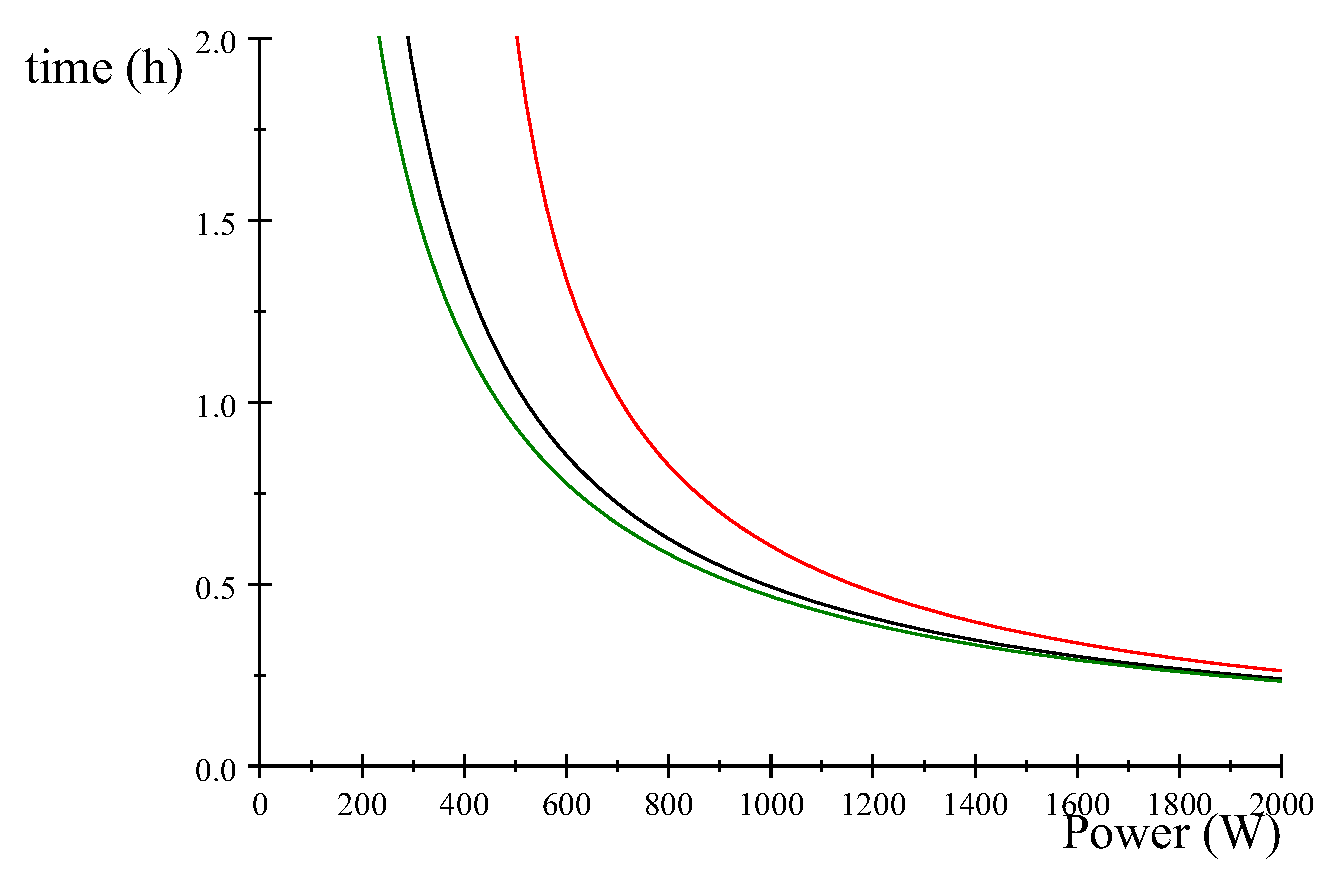
Equation (5) can be inverted to obtain the time needed to raise the water temperature from the ambient temperature to boiling temperatures (), and examples of heating times are shown in Figure 4 for the base case in Table 3.
The green line is the case of ideal insulation (), showing the inverse proportionality of the power and heating time (from the power series limit of ln function):
For ideally insulated systems, doubling the power gives half the heating time. With thermal losses, the heating time increases, and as the power supply approaches the loss rates, the heating times become infinite and the boiling point will not be reached.
Our expectations for the cooking time may be more in terms of absolute times rather than relative times. An increase in the waiting time from 5 min to 10 min may not be judged as significant, but an increase from half an hour to one hour is likely to be experienced as a less acceptable difference. Upscaling of cooking volumes then means high power will be required and sufficient insulation will, in particular, be important for low-power systems.
From these illustrations, some requirements for a heat storage unit for cooking are suggested in Table 4:
1.2. Energy and Power for Frying
Frying is distinguished from cooking in that the frying period for each item is short and in that high temperatures and sufficient heat transfer rates are needed at the frying pan, as illustrated in Figure 3. The heating time is now less of an issue, compared with the cooking case, as the heating is mainly for the frying pan. The frying time and power needed depends on the food item (eggs, pancakes, meat, chapati, injera, etc.) but can be set to be quite constant during the frying process. The need for power control can therefore be less than for the cooking case but the need for temperature control is higher. A high temperature is needed to obtain the desired frying quality of the food items, and the heat transfer has to be sufficiently maintained after the cold batter has been placed on the frying pan.
Some requirements for a heat storage unit for frying can then be added, as noted in Table 5.
1.3. Scaling of Heat Storage Solutions
To heat one liter of water from ambient temperatures to the boiling point (say, an temperature increase) without thermal losses takes somewhat less than . Measurements of cooking energy indicate that some common food types in Uganda (https://mecs.org.uk/wp-content/uploads/2020/10/Uganda-CCT-Report-.pdf, accessed on 20 June 2023) typically require a similar amount of energy for the following boiling period [10]. With anticipated thermal losses, a value of can be a conservative estimate of the energy requirements for cooking rice, and beans can require 3–5 times that amount depending on whether the beans have been pre-soaked or not. This cooking energy requirement can be reduced with improved thermal insulation.
For a concept to be adaptive to the cooking needs from households to institutions, it needs to be scalable, as added to the list of requirement notes with Table 6. For the case of frying, the scaling aspects will relate to whether several fryers can be attached to one up-scaled heat storage unit.
1.4. Socio-Economic Aspects
The socio-economic aspects of cooking technologies are important factors for the successful adoption of new cooking solutions with heat storage. High unit costs in relation to income levels will obviously be a limiting factor and can be taken into account by the engineers involved in the development process. Social factors may, however, be more of a challenge to include in the development phase, as they are less clear for the technically oriented developers. A technically excellent system may not be used if it interferes with established food cultures and cooking habits. Socio-economic aspects are not considered here but can be noted as an important requirement for the successful acceptance of a final system (Table 7).
2. Why Heat Storage?
A heat storage concept gives more flexibility in the development of clean and sustainable cooking solutions (Figure 1). The variation of the solar radiation with the weather (clouds and humidity) can make direct solar-based cooking solutions unreliable, and a solar energy storage system will solve the solar intermittency problem. A storage solution can also be useful as a way of converting a low-power solar energy source to high-power cooking energy. The two different types of storage motivations are discussed further below.
2.1. Energy Storage for Off-Sun Cooking
An energy collection system can be dimensioned such that it can provide sufficient power for direct cooking and also for the accumulation of excess power into energy storage. Cooking can then be initiated from the time the solar radiation is available, and the storage will provide the buffer power needed at times of intermittent sunshine. A buffer storage then need not be large. However, as the energy collection for a direct cooking system now has quite a high capacity, the storage unit can be scaled accordingly to facilitate cooking solely made on the heat storage unit during off-sun times as well (evenings). With good insulation, a heat storage unit can also then tentatively provide cooking power in the morning.
The principles of such an energy storage solution are illustrated in Figure 5. The principles of an excess energy to storage system and from the storage unit to a cooker are analogous to an electrical system. A charge controller can manage the incoming power distribution between an electrical battery and the load. In a thermal energy system, the storage unit can similarly act as a buffer by absorbing excess energy during available sunshine and releasing cooking power when the sun power fails.
The design requirements for a combined heat collection and storage system for direct cooking can then be proposed, as noted in Table 8.
2.2. Conversion of Low-Power Energy Source to High-Power Cooking Energy
A few PV panels (a few hundred Watts) can, together with electrical batteries, serve the need for lighting and for small power appliances. But such a low-power system will not be practical for direct cooking purposes for a family (estimated to comprise five persons), as the heating time will be very long when the power input is low. A similar principle for electrical energy storage can then be applied to the heat storage case, as illustrated in Figure 5b. A low-power source can, over time, accumulate energy into a high temperature energy storage to yield high-power cooking energy for shorter times. A single PV panel may have too little power for direct cooking but may facilitate some evening cooking after energy accumulation during the day. A low-power indirect system can also be useful for off-grid locations which are not in use for long periods of time, e.g., cottages which are visited on a weekly/monthly basis.
The two motivations for a heat storage unit, as well as the scaling properties of this system, have implications for the design of both the storage unit and the charging system. A high temperature is needed in the heat storage to achieve sufficient power for the cooker or fryer. If direct cooking from the sun is desired, a high-power energy source is also needed (e.g., several PV panels or heat collectors).
We can note (Table 9) a heat retention requirement for indirect systems and in particular for low-power systems:
A direct system with a buffer storage is expected to be a favorable solution. However, this may not always be feasible, depending on the scale of the cooking in comparison with the available power sources as well as cost limitations.
3. Heat Collection Methods
Solar heat collection can be achieved through the direct conversion of solar radiation to heat or indirectly through PV power with heating elements in a heat storage unit. As the storage temperatures should be high (e.g., ) in order to provide short heating times for cooking, or sufficient temperatures for frying, a direct system is expected to involve solar concentrators (SCs). Such systems have been explored for various concentrating geometries with both natural and forced circulations for the heat transfers between a heat absorber and a storage unit. SCs will work but tend to become somewhat elaborate, as solar tracking is required as well as heat transfer loops, often with high temperature pumps or fans.
The conversion of water heating panels (here, termed HPs) to be used with oil for high temperature systems can be an option, and, in particular, evacuated tube systems have the potential to reach quite high temperatures. Such systems are passive (natural circulation) and static (no solar tracking), and some practical tests so far show stagnated temperatures reaching about [11]. The energy collection efficiency is, however, reduced as the storage temperature increases.
The indirect heating of a heat storage unit through PV power is becoming a cost competitive option for direct solar heat collection systems. A comparison between the efficiencies of PV and HP heating systems is illustrated computationally in Figure 6 for a hypothetical case, using some approximate loss estimates (Table 10).
The graphs in Figure 7 are derived from two energy balances, one for the oil in the storage (no thermal losses)
and the other as a steady state balance on the HP:
is the temperature associated with the HP, is the temperature of the oil, is solar power of the HP, is the power from the PV panels, represents the heat transfer parameters from the HP to the oil, and represents the heat transfer parameters from the HP to the ambient (losses).
Inserting from Equation (9) into Equation (8) and solving for gives us
Heat transfer areas and coefficients are also needed between the HP and the oil storage container, and this will influence the sample computations. A high heat transfer gives us similar temperatures in the HP and the heat storage unit whereas low heat transfer coefficients will give higher HP temperatures, more losses, and lower solar energy conversion efficiencies. Here, we simply apply values which illustrate a case where the HP efficiency approaches the PV efficiencies at some reasonable temperature values.
Figure 6 shows that the rate of temperature rise in 25 L of oil heated from an HP (from Equation (10)) decreases as the losses increase with increasing oil temperatures. The efficiency is also plotted, illustrating that an HP efficiency will decay with temperatures in comparison with a PV efficiency which is independent of the load temperature. A combination of the two could increase the total efficiencies and lift the oil temperatures to higher values more suitable for cooking. However, care must be taken when the saturation temperatures of the HP are approached, as the storage temperatures can exceed the HP temperatures and possibly lead to unintentional losses through the HP. This can occur if the PV power dominates or if the heat transfer from the HP to the oil storage is poor. Hybrid systems may be better accommodated with two tanks, one for preheating (HP) and one for top heating (PV).
We can then propose another desired property of a heat storage system for cooking (Table 11).
4. Storage Types
The storage types for discussion here are sensible heat systems and latent heat systems, with applications to cooking and frying.
4.1. Latent Heat
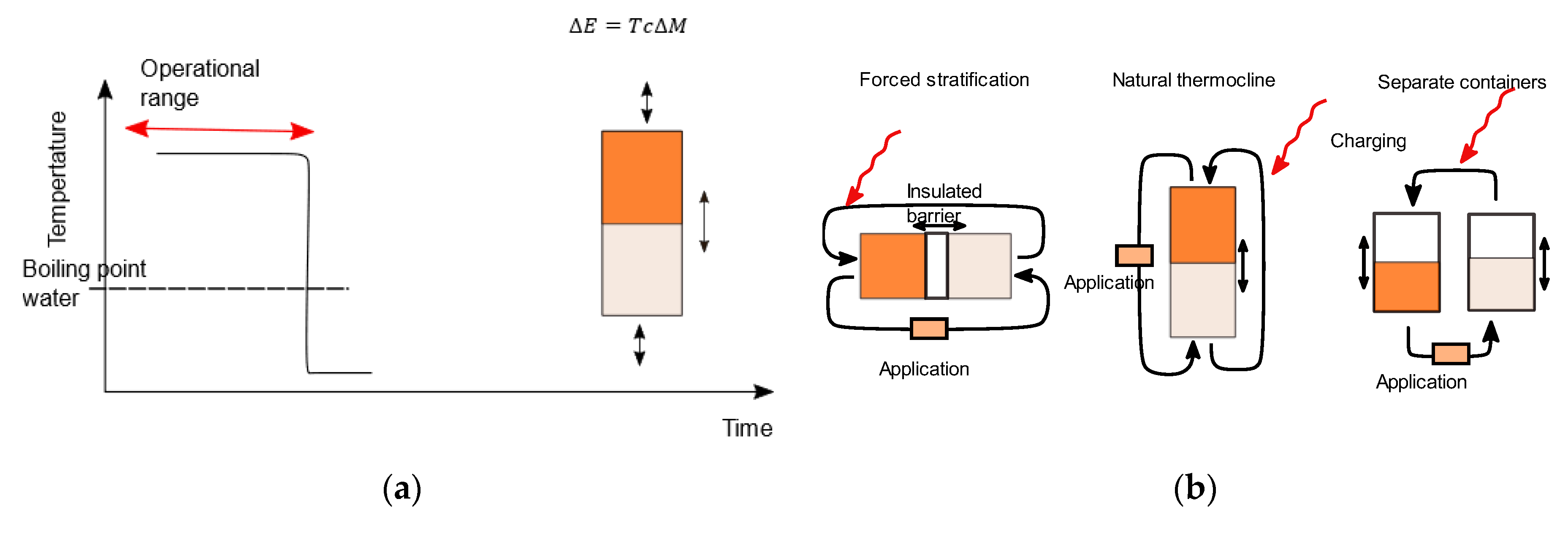
Latent heat storage methods exploit the fact that energy transfer is required for a phase change to occur. Gas-to-liquid or liquid-to-solid phase changes release heat, whereas heat is required for the opposite changes. A singe component two-phase system at equilibrium will be at the pressure–temperature saturation line, whereas a multicomponent system has an equilibrium region in a pressure–temperature diagram. Water is a single component system which boils at atmospheric pressure at about 100 °C, and the operation of an ideal single component latent heat case is illustrated in Figure 7.
The energy change (ΔE) for a mass (M) undergoing a phase change is
where is the latent heat (J/kg).
We can note two positive aspects of a latent heat storage system:
- ✓
- The storage is at a near constant temperature in the phase change region. This can, in particular, be a desirable property for frying and baking systems.
- ✓
- The energy density can be high. If the storage system is operated in the phase change region, the energy per volume is normally much higher than what would be feasible with sensible heat alone at similar volumes.
Limitations may be related to the following:
- ○
- The identification of a Phase Change Material (PCM) which has a suitable temperature range for cooking.
- ○
- Operational safety: the PCM should not pose health or safety threats.
- ○
- Durability: the PCM should tolerate very many cycles without degradation.
4.2. Sensible Heat Storage at a Uniform Temperature
Figure 8 illustrates the case of a sensible heat storage system with a uniform temperature distribution. The stored thermal energy due to a temperature change can be written as follows:
A positive aspect of such a sensible heat storage system is the following:
- ✓
- The storage can be made with low-cost materials, which can also tolerate very high temperatures (e.g., air and rock beds).
The drawbacks of uniform sensible heat storage systems are the following:
- ○
- Varying temperature in time: The temperature in the storage system varies with the charging or discharging of the storage system. This drawback can be somewhat remediated by oversizing the storage unit (Figure 8).
- ○
- Reduced exergy during charging: If we define the exergy of a heat storage system as the useful energy available for cooking, then a mixed storage system tends to decrease the incoming energy quality by lowering the source temperature due to the thermal mixing in the storage system. To maintain a boiling state, temperatures above the boiling point are needed. When starting from a cold storage state, the user has to wait for the charging of the full body of the storage system before it reaches useful temperatures for cooking.
4.3. Thermally Stratified Sensible Heat Storage
Contrary to thermally uniform sensible heat storage systems, cases with separate cold and hot parts of a heat storage unit are illustrated in Figure 9. This can be achieved with an energy exchange by the circulation of mass in and out of the storage unit. The energy change in the storage system can then be written as follows:
Thermally separated storage solutions can have similar benefits as for latent heat systems, as the temperature of the heat transfer medium supplied to the application can be constant and heat can be extracted at the same temperature as the charging temperature. The hot and cold parts can be separated by different methods (Figure 9):
- Natural thermoclines:Hot fluid can remain on top of a cold fluid as the fluid density decreases with increasing temperature. Natural thermoclines can, however, decay in time due to thermal conduction.
- Forced stratification:The hot and cold fluids can be separated by a physical barrier. This can be challenging for a vertical system, as wall leakage is difficult to avoid (the barrier must be buoyant between hot and cold temperatures) but is feasible for horizontal systems using an insulating piston.
- Separate containers:The hot and cold fluids can be stored in two separate containers.
Some attractive features of the separation of the cold and the hot storage parts are as follows:
- ✓
- Recovery of input energy quality:By reversing the flow, the hot fluid entering the storage system can be recovered for immediate use, with a high temperature fluid in and a high temperature fluid out at all times.
- ✓
- Control of cooking power:The power to the application can be controlled by the flow rate of the storage fluid.
- ✓
- Two tanks can serve hybrid energy sources:Electrical heating (PV) can be applied to the hot tank and heating panels (HPs) to the cold tank.
- ✓
- A single tank with natural thermoclines can support rock bed solutions. For oil systems, this saves the amount of oil needed. For air systems, the rock bed can support heat storage at very high temperatures.
Some drawbacks of a thermal stratification system are as follows:
- ○
- Temperature control of the source:A temperature control on the fluid entering the storage is required.
- ○
- Circulation of heat transfer fluids:Natural circulation can be an option in the thermocline case, but a pump is needed in the two-tank case as well as the horizontal piston case.
- ○
- Two tanks:Two tanks require more insulation than one. Two tanks will also rule out the use of rock beds in the containers.
4.4. Comparing the Charging of Latent Heat Storage and Sensible Heat Storage
The energy differences between two storage units of equal volumes can be illustrated by how the temperature of the storage system changes during charging with a constant power source. The volumetric heat capacities are compared in Figure 10, where the latent heat is illustrated in terms of an apparent heat capacity across a small temperature-melting range (Equation (1)). The oil and the Solar Salt have quite similar values, and both are considerably lower than for water.
Figure 11 shows the temperature rise when charging 25 L of oil or solar salt, starting from using 1500 W of heating power (Equation (3) without losses). Both the piecewise estimated heat capacity for solar salt (Equation (1) from [9]) and the curve fitted function (Equation (2)) are included, which also illustrate the inaccuracies of the apparent heat capacity estimates. After about two hours, the limiting oil temperature (here set at ) is reached and the charging has to stop. The solar salt case can be further charged before reaching the same temperature. The temperature rise without losses is given by
where P is the power, is the initial temperature, V is the volume, is the volumetric heat capacity, and t is the time.
The useful energy, integrated for the temperature range of T = to , is about two times higher for the solar salt than for oil and more than three times in the range of T = to . The quality of the energy, in terms of capacity for short cooking times, is therefore larger for the latent heat case than for oil, as illustrated further below in computational cooking cases.
5. Comparing Cooking on Different Storage Types
Qualitative comparisons are computationally illustrated below on how the different storage options can perform regarding the heating of water.
A drawback of a uniform sensible heat storage system is that the temperature of the storage is changing during the charging and discharging of the storage system. When the storage system’s temperature decreases, so does the available power from the storage unit, as the heat transfer from the storage unit to the application is driven by the temperature difference.
A latent heat storage unit can maintain its temperature during cooking. For a sensible heat system, with ideal thermal stratification, the heat supply to the application is also at a constant temperature in the hot layer in the storage unit. This will also be available at times with only partially charged heat storage systems, whereas a thermally uniform storage system and a latent heat storage system need to be fully charged to reach the optimum capacity of the power supply to the cooker.
The heating of water in a cooker from the three types of storage systems can be illustrated for a sample case given in Table 12.
5.1. Uniform Sensible Heat Storage
Energy balances for the heat storage unit and for the water in the cooker give the time evolution of the temperatures during the heat transfer. The energy balances are as follows:
To avoid ill-defined fractions where both the nominator and denominator approach zero, the case can be reformulated using the temperature difference as a variable, For the ideal case without losses, this becomes:
The temperature difference then decays exponentially from an initial value :
The time evolution of the temperature difference can then be applied in the energy balances for the storage unit and the water (Equation (15)), giving the water and storage temperatures in time:
Figure 12 shows sample computations for the temperatures in the storage unit and in the cooker (water). The heat transfer coefficient from the storage unit to the cooker is arbitrarily set to 200 and will depend on the cooker’s geometry and the quality of the thermal contact with the storage unit.
A storage of 25 L of oil charged to is used to raise the temperature of 5 L of water from to . When this is repeated several times, the temperature in the uniform storage system decays for each cycle, which gives subsequent longer heating times of the water.
The third heating cycle on the oil heat storage system will require about twice the time compared with the first cycle, and the fourth cycle will not reach boiling temperatures.
5.2. Latent Heat Storage
The sample case can be illustrated for the case of ideal latent heat storage systems by similar computations but now by using Solar Salt properties and the apparent heat capacity function of Equation (2). As the heat capacity function is complex, the equivalent computations for the solar salt were made numerically (using Scientific Work Place). A total of 25 L of solar salt at has a higher total energy than 25 L of oil at , and the two would have a comparable energy for about 36 L of oil.
Figure 13 shows sample computations with 25 L of solar salt. Two differences can be noted compared with the 25 L oil storage case. One is that the latent heat storage system can heat more cycles of water, and the other is the effect of the phase change regions. The first region, at about , gives short cooking times for the first three cycles, as the storage temperature remains near constant. The second phase change region is at about . As this is close to the boiling point of water, this region will not be important for the heating of water but can be useful for maintaining the simmering of food at the boiling point.
The shape of the temperature profile in the time of the latent heat storage system during heat extraction can potentially be calibrated to a suitable amount of water and beans. The water can efficiently be brought to the boiling point at the phase-change temperature and long-term cooking can follow with lower heat transfer rates due to decreasing storage temperatures.
5.3. Oversized Uniform Sensible Heat Storage
A uniform sensible heat storage system can compare better with a latent heat storage system by increasing the size of the storage unit. This may be a feasible solution, and the demand for oil volumes may also be reduced by using a rock bed in the storage unit (the volumetric heat capacities of rocks and oils are comparable).
Figure 14 shows sample computations of a sensible heat storage system similar to Figure 12 but now with double the heat storage volume (50 L instead of 25 L).
If an oversized storage unit could be used in such a way that it is not depleted below a given high temperature level (requiring sufficient size and insulation), then a uniform sensible heat storage system could become an alternative to the smaller latent heat storage option. The heat required for cooking would entail small temperature changes in the large storage unit. The challenge would be a long recharging time if the storage should become depleted.
5.4. Stratified Sensible Heat Storage
For the case of heat transfer from a stratified storage system to the cooker, the heat transfer is now by a mass flow from the storage unit through the cooker. When a hot stream delivers energy to a co-current cold stream, the heat transfer is given by the Logarithmic Mean Averaged Temperature (LMTD) difference between the streams. The energy balance is then written as follows:
where is the oil temperature from the storage unit into the cooker and is the oil temperature leaving the cooker. is the temperature difference between the oil and the cooker at the cooker inlet and is the temperature difference at the outlet. G is the flow rate and the heat capacity of the oil. Assuming a uniform water temperature in the cooker, we have , which leads to the following:
Inserting Equation (20) into Equation (19) and solving for gives and the outlet temperature of the cooker becomes
signifies the relative importance of the heat transfer to the water and the heat flow through the cooker.
The water temperature is given from the water energy balance:
Substituting for and gives the rise in the water temperature as follows:
For the uniform sensible heat case and the latent heat case, the heat transfer is determined by the conditions on the storage side and the heat transfer properties of the cooker (AU). For the stratified sensible heat case, the heat transfer now includes a flow rate (G) as well.
- For the case of a high flow rate compared with the heat transfer part (small ), approaches , and the rise in the water temperature becomes similar to the latent heat case. The cost is high thermal losses as oil leaves the cooker at a high temperature.
- For the case of a high heat transfer rate and/or low flow rates (large ), the outlet temperature from the cooker will approach the water temperature. This causes small thermal losses, as the oil delivers much of its energy to the water, but the cost is long heating times.
Figure 15 shows computational examples where the water temperature is from the solution of Equation (24)) using similar heat transfer rates (UA) as for the sensible heat case in Table 11. The low flow rate case would give five numbers of heating, whereas the high flow rate case would give only one. A stratified heat storage system thus has the potential of providing more useful energy from a partially charged storage system than a uniform heat storage system, although it would do so at long heating times.
A comparison with a uniform sensible heat cooking case is shown in Figure 16. A 25 kg oil thermal storage system charged to can bring 5 L of water to the boiling point three times, and the fourth time does not reach boiling temperatures as the storage temperature has become too low.
The heating times using flow rates of about 2, 3, and 10 mL/s for the flowing case are plotted in the same graph and give the equivalent of 4, 3, and 1 heating cycles of water. This is equivalent to 25%, 33%, and 100% charged heat storage systems.
The computational comparisons are not directly comparable, as the same heat transfer rates to the cooker have been assumed (AU values). This will be different for a flowing and a stagnant case. However, the sample computations can serve as an illustration of the following differences between a stratified and a uniform thermal storage system:
- For an ideal thermally stratified heat storage system, the upper layer will be at a set hot temperature, the lower layer will be cold, and a thermocline will move downwards during charging. For a thermally uniform case, the mixing gives a uniform temperature which will then gradually rise during charging.
- When starting from a thermally empty storage state, the stratified case can provide the heating of 5 L of water after a quarter of the full charging has been reached (at 2 mL/s). The uniform case would only have reached a mixture storage temperature not more than at the quarter storage capacity. As the thermocline moves downwards, more water can be heated to the boiling point, whereas the uniform case needs to wait until the full storage is above , when 5 L can be heated to the boiling point in about one hour (see also the similar case of Figure 12).
- The more direct availability of the charging energy is a positive property of the stratified storage system compared with the uniform storage system. The exergy of the input energy is retained for the stratified case but deteriorates for the uniform case. This property of a stratified system is also important if the storage unit is intended to be used as a buffer where direct cooking is interrupted by intermittent sunshine.
- When starting from a fully charged storage state, the differences between the two cases are smaller, and the flow rate can be set to achieve a similar number of heating cycles for a uniform storage system.
6. Heat Transfer Options
The heat transfer from a heat storage unit to the cooking application is the third challenge of a solar cooking system, in addition to the energy collection methods and the heat storage solutions. The heat transfer should be efficient, so as to avoid long waiting times for the heating, and preferably adjustable, so as to regulate the heat transfer from high values during heating to lower values during cooking.
6.1. Heat Pipes
The heat transfer in a heat pipe is by the evaporation of a working fluid in the heated part (the heat storage unit) and condensation in the cold part (the cooking application). The condensate can return from the cold side to the hot side by gravitationally driven flows in a separate pipe or as a counter current two-phase flow in a common pipe. The term “heat pipe” is often used for the particular case with capillary liquid transports in a wick, but here, it is applied as a more general term. The attractive aspect of a heat pipe is that the temperature is ideally equal at the cold and the hot parts. Another attractive property is that the heat transfer can be stopped by a valve which hinders the liquid and vapor transports. When the liquid transport is by capillary flow in a wick, the heat pipe can also be horizontal.
The heat transfer for heat pipes can be written as
where is the phase change enthalpy and G is the vapor mass flow rate from the hot to the cold side, which is equal to the return rate of the condensate to the hot side. The pressure is quite similar along the pipe, giving similar temperatures on both ends, according to the saturation conditions. The pressure will be according to the energy balance where the heat supply and heat extraction are in balance.
6.2. Conduction
The heat transfer from a storage unit to a cooker can be made by conduction through fins extending into the storage unit. The heat transfer rate will depend on the thermal conductivity, the cross section and surface of the of the fins, which may need to be quite large for some cases, notably for latent heat storage media which often have very low thermal conductivities. Control of the heat transfer rates can be difficult with conduction-based systems.
The heat transfer from a storage unit has resistances due to the hot side (characteristic heat transfer coefficient and surface for the fins), the conduction in the fins (characteristic thermal conductivity k, fin cross section A, and length L), and the cooking side (characteristic ). The total resistance to the heat transfer between the storage temperature and the water temperature is then dependent on the conductor geometry:
is the heat transfer rate, resulting from the temperature difference between the storage and the cooker
6.3. Circulation with a Heat Transfer Fluid
The heat transfer between the storage unit and the cooker can be achieved by circulation of a heat transfer fluid. Unless the fluid itself is part of the heat storage medium, a heat exchanger is needed in the storage unit. For a rock bed heat storage system, the fluid circulates through the rocks, and for a two-tank system, the fluid itself is the heat storage medium.
A circulation pump would require power (a battery for the off-sun case) and must be high-temperature tolerant (above ).
Natural circulation can replace a pump for cases where the density difference between hot and cold oil is sufficient to drive a flow by the force of gravity (thermosyphon). The expansion of some oils can be quite large and provide a sufficient driving force for circulation to a cooker. The temperature difference can arise from a local heat source (heating elements) and/or from a heat sink (a cooker). The flow rate is then determined from an integrated force balance between friction and gravity in the closed loop system:
is the angle with the horizontal, A is the flow cross-section, g the gravitational acceleration, is the density which depends on the temperature at each location in the loop, and is the friction force per friction area at each location in the closed loop system. For a pipe flow, the friction term can be written in terms of standard friction factors, whereas friction relations for rock beds are not well-established.
7. Examples of Heat Storage Systems for Cooking
The following gives examples of solutions for heat storage for cooking and frying which were constructed and tested in the NTNU laboratories. Several other solutions using solar concentrators were also tested as part of a long-term collaboration with a group of African universities. The objectives were to arrive at solutions which have a sufficient robustness, simplicity, cost, and social acceptance to become the basis for local production and implementation in the African partner countries.
7.1. Forced Thermal Stratification
Figure 17 illustrates the principle of using an insulating piston to separate hot and cold oil in a tubular heat storage system. The concept can also be adopted to a vertical heat storage system with natural thermal stratification. A positive aspect of a vertical storage system without a piston is that the container can be a rock bed. A drawback is the degradation of the thermal fronts in time.
A pump circulates the thermal oil through the heater, which can be a direct solar collector or one or several electric heaters (PV, wind, and hydro). A two-way valve at the inlet of the pump controls the flow through the cooker, and a thermostat valve opens at a preset temperature (about ) and diverts the flow to two possible outlets. The two operational modes are as follows:
Cooking—the two-way valve is open to the cooker.
- For a cold thermostat valve (insufficient fluid temperatures from the heater), the flow is directed to the cold side of the storage unit, and the piston forces the hot fluid to the cooker.
- For a hot thermostat valve, the flow is directed to the cooker.
Charging—the two-way valve is closed to the cooker.
- For a cold thermostat valve (fluid temperature from heater above set point), the flow is directed to circulate through the heater.
- For a hot thermostat valve, the flow goes to the hot side of the storage unit.
A test system was constructed in the laboratory [12] (see pictures in Figure 18). A thermostat valve was constructed and built using an electric actuator to drive a slider valve which is open to the atmosphere (a fully mechanical actuator can be a better alternative). A piston was machined with good accuracy and tolerates the target temperature of about . (Peek material was used in the experiments.) The concept was demonstrated using a copper coil in place of a cooker and two valves instead of a single two-way valve.
7.2. PCM Fryer
A commercial aluminum frying pan with integrated heating elements was fitted with conducting fins and inserted into an insulated container with Solar Salt—see Figure 18. With heating elements attached to the pan, the PCM will start melting from the top, which is important for the free expansion of the liquid PCM as it melts at the surface of the fins. The fryer was successfully tested with crepes, pancakes, and the Ethiopian injera bread. A silicon-based baking sheet can be used on top of the frying pan to hinder sticking on the surface, which could otherwise be a problem as the surface remains hot for a charged storage system.
When heat is supplied to the unit (e.g., from the PV panels), the pan becomes hot, and frying can commence early. Excess heat (e.g., when not frying) is then absorbed by the storage unit through the conducting fins.
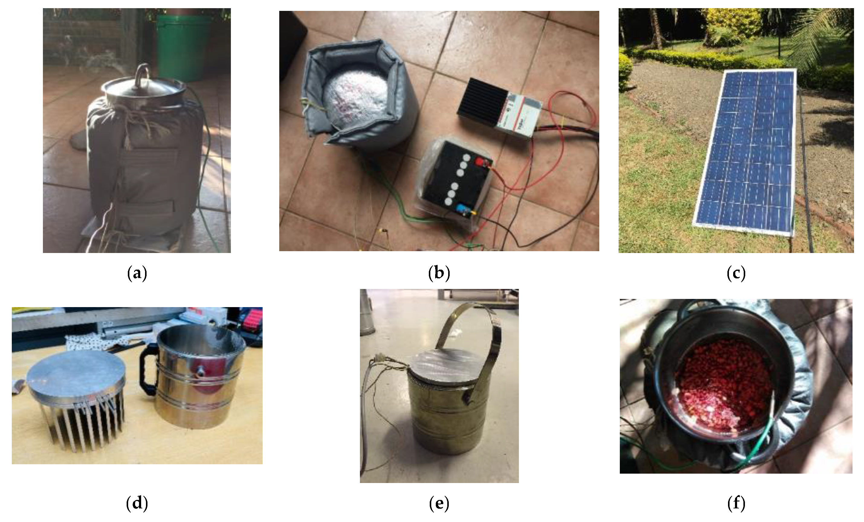
A small-scale version of the PCM fryer system was also made to demonstrate cooking for one meal, as shown in Figure 19. The top plate was now fitted with heating elements which were suitable for one or two PV panels. During sunshine, a battery charge controller now diverts the excess energy to the heat storage unit. The energy in the solar salt was suitable for cooking a pot of beans. The amount of beans can be calibrated to the storage size, such that the pot can be left alone with the beans, and when the storage is depleted, the beans are ready, after 2–3 h.
7.3. Fryer with Combined PCM and Oil
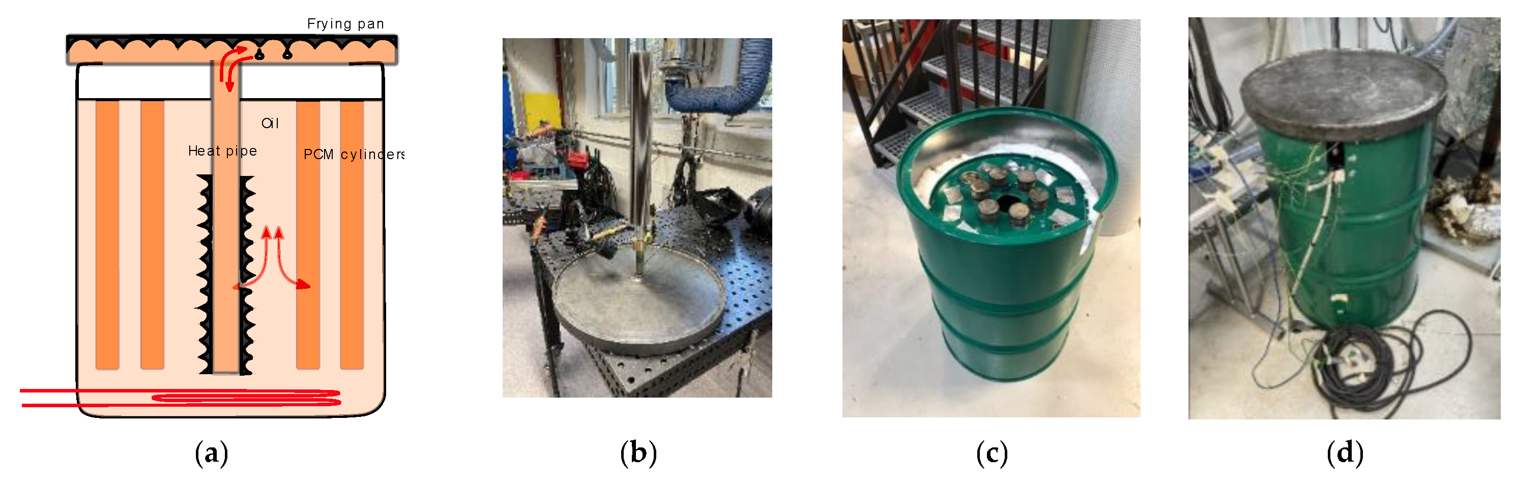
A second version of a PCM (solar salt) fryer was tested using solar salt contained in cylinders which are immersed into a thermal oil container (or alternatively with edible oil)—see Figure 20 and the Acknowledgment section. The oil provides the heat transfer between the PCM cylinders to a heat pipe fryer. The evaporating part of the heat pipe is installed in the oil and the condensing part is the inside of a hollow frying pan.
The differences of the pure PCM fryer with conducting fins are that the heat transfer can be shut off with a valve, there is more flexibility of the heating elements (one or several heat sources), and several frying pans can be attached to a single heat storage system (with curved heat pipes). A drawback is that the heat storage unit must be fully charged before frying can start, so that if the storage unit is allowed to cool down, the recharging times can be large. The production of the system is also more difficult with a hollow pan to be evacuated and filled with a heat pipe fluid. Propylene Glycol was used, instead of water, as the working fluid to keep the pressure in the heat pipe low (below 3 bar) also at high temperatures ().
The melting point of solar salt is about , and the top plate achieved about (due to imperfect insulation), which is suitable for frying. Again, a silicon baking film proved to be useful in the frying tests of the Ethiopian injera, which gives quicker frying times than using a second frying pan positioned on the top plate.
7.4. Oil-Based Single-Tank System
A single tank sensible heat storage system (see Figure 21 and the Acknowledgment section), was made using the expansion of the oil as a temperature control method. A heating element is positioned in a funnel under a cooker, and upon heating, the hot oil rises and heats the cooker. When the oil expands, it overflows the funnel top, and natural circulation is initiated, giving the propagation of a thermal front downwards on the storage side. Without heating, the natural circulation reverses, bringing hot oil from the storage side to the cooker. The height of the funnel can be adjusted to set the overflow temperature as well as the heat transfer rate during circulation. The amount of oil can be reduced by using a rock bed on the storage side.
The heat transfer rate can be adjusted by the elevation of the funnel. Cooking experiments with rice and beans showed good cooking behaviors without sticking or burning the food.
The single-tank system was modified by moving the cooker outside of the storage system, as shown in Figure 22. The same principle of natural circulation is employed with the expansion-based temperature control method. Moving the cooker outside gives better opportunities for the upscaling of the storage system, as the storage unit can now be placed on the outside of a wall and the cooker on the inside. As for the case with integrated cookers, adding a rock bed to the storage system was successfully tested. The cooking rate and the temperature can be adjusted with a floater arrangement for changing the oil levels. Pumps will be needed if the storage unit is up-scaled and operated with several cookers.
7.5. Three-Tank System
A three-tank concept was tested, where the hot and cold oils were separated into different containers—see Figure 23. A hot tank has heating elements and a thermostat valve which opens for the cold oil from a tank above when the oil reaches a set temperature (). A fully mechanical thermostat valve was developed in such a way that it can be constructed locally, using a pipe-in-pipe arrangement with a bi-metal spiral. During the day, hot oil accumulates in the hot tank and can be drained through a cooker to a residual oil tank below. The residual oil can be hand-pumped to the top tank at the end of the day or at suitable intervals. If an electric pump is introduced, the lower tank with residual oil is not necessary.
A version of the three-tank system was also constructed in Arusha, Tanzania [13]. The system has some benefits (it is open for the preheating of the oil with evacuated tube heaters) but can become somewhat elaborate with the insulation of three tanks.
7.6. Comparisons of the Concepts
The requirement notes, which were suggested during the discussions above, are compared in relation to the cases which have been presented in Table 13.
Experiences with the testing of prototypes in the laboratory environment show that technically simple and robust solutions on heat storage for cooking can be achieved. It is, however, challenging to fulfil all the requirements in Table 12 in one single concept.
Some edible oils can be used for the sensible heat case, but synthetic thermal oils are also commonly available. The single-tank system can be attractive due to the simplicity of the concept, and as it can be designed for both smaller and larger cooking needs.
7.7. Notes on Further Work
The household demand for thermal energy is higher than for electrical power and, in particular, is so for consumers in Sub-Saharan Africa. As energy systems worldwide have to terminate the use of fossil fuels, the need for energy storage solutions increases, as solar and wind power sources are intermittent. For Distributed Energy Systems, which are particularly relevant options for African off-grid regions, the energy storage systems can also be distributed and scaled down to household levels. This gives opportunities for local research and development, tailored to local resources and local needs. The presented cases, as well as a number of other direct solar thermal concepts, were derived for the African context. Similar developments could very well be made based on the European case, where LPG is often used for cooking, and where the general requirement on technical simplicity is of less concern. Other options than the ones discussed here should also be explored, e.g., thermo-chemical heat storage solutions.
The strategy in the collaboration between NTNU and a group of African universities has been firstly to target the exploration of technical solutions which can be feasible for implementation at institutional levels. Secondly, to down-scale and optimize for household levels, where the socio-economic aspects are expected to be of higher concern.
8. Conclusions
Energy storage technology is required for the transition from fossil fuels towards renewable energy solutions. The case of thermal energy storage for cooking is open for innovation and some options based on the electrical heating (e.g., Photo Voltaic, PV) of sensible and latent heat storage systems were discussed in the form of computational sample cases. A set of requirements for solar-based cookers with heat storage units were suggested, and some pilot systems which fulfil many of the suggested requirements were briefly presented. Latent heat storage systems can be suitable for frying cases. Sensible heat storage systems (oil and rock bed) can be suitable for cooking, as the cooking power can be regulated.
The presented cases are based on the electrical heating of the heat storage systems. The direct solar powering of heat storage units with solar concentrators represents other options. The conclusion from our experiences of both indirect electrical (PV) and direct solar systems for charging heat storage units for cooking is that although the energy efficiencies of direct systems can be higher than the PV cases, the aspects of simplicity and robustness, as well as the ability to also harvest energy from diffuse solar radiation, favor PV systems.
Direct solar cooking has a long history, and very many solutions are available, from stationary box and panel cookers to concentrators and funnels for baking, frying, and for cooking. Direct cookers have, however, not been widely adopted, and the inclusion of a heat storage component may provide better prospects for the uptake of solar-based cooking solutions.
Funding
The laboratory work has been funded from NTNU, the Department of Energy and Process Engineering, NTNU Discovery, and from NORAD (The Norwegian Agency for Development Cooperation) through collaboration projects with a group of African universities (EnPe “Capacity5 project” and Norhed programs “Energy Technology Network”).
Data Availability Statement
Some Web Resources on Clean Cooking (accessed during 1 January 2023): https://collaboration.worldbank.org/content/sites/collaboration-for-development/en/groups/clean-cooking-and-heating-solutions.html. https://www.esmap.org/. https://www.esmap.org/node/181461. Clean Cooking Program. https://www.esmap.org/clean-cooking-fund. https://www.unhcr.org/. https://www.who.int/initiatives/health-and-energy-platform-of-action. https://www.humanitarianenergy.org/thematic-working-areas/clean-energy-challenge/ https://www.cafi.org/news-centre/new-fund-develop-sustainable-energy-drc https://www.wfp.org/publications/2021-re-energising-cooking-schools https://www.seforall.org/clean-cooking. https://cleancooking.org/wp-content/facit/assets-facit/Comparative-Analysis-for-Fuels-Executive-Summary.pdf. https://www.solarcookers.org/. Fryer with combined PCM and Oil: Abraham Parra. Oil-based single tank system: Gunn Helen Nylund, Andreas Bjørhol, Alexander Peter Olsen.
Acknowledgments
The collaboration with masters and Ph.D. students on the experimental side is acknowledged, and the details of the concepts are to be published with the students.
Conflicts of Interest
The authors declare no conflict of interest.
References
- Arunachala, U.; Kundapur, A. Cost-effective solar cookers: A global review. Sol. Energy 2020, 207, 903–916. [Google Scholar] [CrossRef]
- Cuce, E.; Cuce, P.M. A comprehensive review on solar cookers. Appl. Energy 2013, 102, 1399–1421. [Google Scholar] [CrossRef]
- Leary, J.; Leach, M.; Batchelor, S.; Scott, N.; Brown, E. Battery-supported eCooking: A transformative opportunity for 2.6 billion people who still cook with biomass. Energy Policy 2021, 159, 112619. [Google Scholar] [CrossRef]
- Alva, G.; Lin, Y.; Fang, G. An overview of thermal energy storage systems. Energy 2018, 144, 341–378. [Google Scholar] [CrossRef]
- Sharma, A.; Chen, C.; Murty, V.; Shukla, A. Solar cooker with latent heat storage systems: A review. Renew. Sustain. Energy Rev. 2009, 13, 1599–1605. [Google Scholar] [CrossRef]
- Omara, A.A.; Abuelnuor, A.A.; Mohammed, H.A.; Habibi, D.; Younis, O. Improving solar cooker performance using phase change materials: A comprehensive review. Sol. Energy 2020, 207, 539–563. [Google Scholar] [CrossRef]
- Lentswe, K.; Mawire, A.; Owusu, P.; Shobo, A. A review of parabolic solar cookers with thermal energy storage. Heliyon 2021, 7, e08226. [Google Scholar] [CrossRef] [PubMed]
- Aramesh, M.; Ghalebani, M.; Kasaeian, A.; Zamani, H.; Lorenzini, G.; Mahian, O.; Wongwises, S. A review of recent advances in solar cooking technology. Renew. Energy 2019, 140, 419–435. [Google Scholar] [CrossRef]
- Foong, C.W.; Nydal, O.J.; Løvseth, J. Investigation of a small scale double-reflector solar concentrating system with high temperature heat storage. Appl. Therm. Eng. 2011, 31, 1807–1815. [Google Scholar] [CrossRef]
- Kajumba, P.K.; Okello, D.; Nyeinga, K.; Nydal, O.J. Assessment of the energy needs for cooking local food in Uganda: A strategy for sizing thermal energy storage with cooker system. Energy Sustain. Dev. 2022, 67, 67–80. [Google Scholar] [CrossRef]
- Nébié, J.; Zongo, S.; Tubreoumya, G.C.; Zongo, A.S.; Konkobo, I.; Bagré, B.; Diané, A.; Daho, T.; Igo, S.W.; Zeghmati, B.; et al. Performance Assessment of a Box Type Solar Cooker Using Jatropha Oil as a Heat Storage Material. Energy Power Eng. 2022, 14, 124–132. [Google Scholar] [CrossRef]
- Nydal, O.J.; Fosseng, S.D.; Skahjem, R. Oil based solar heat collection and storage. In Proceedings of the Southern African Solar Energy Conference, Stellenbosch, South Africa, 31 October–2 November 2016. [Google Scholar]
- Nydal, O.J.; Thaule, S.; Kolderup, M.; Gustafson, K.; Bjerre, P. Passive Solar System to Store Heat for Cooking; ISES Solar World Congress: Goteborg, Sweden, 2019. [Google Scholar]
Figure 1.
Inserting a heat storage unit between the fuel and cooker gives flexibility and opens for innovation in the development of clean cooking solutions.
Figure 1.
Inserting a heat storage unit between the fuel and cooker gives flexibility and opens for innovation in the development of clean cooking solutions.

Figure 2.
Measured heat capacities for Solar Salt (black, data from [9]) and curve fitted to Gaussian functions (red, Equation (2)). Two phase-change temperatures are noted for Solar Salt.
Figure 2.
Measured heat capacities for Solar Salt (black, data from [9]) and curve fitted to Gaussian functions (red, Equation (2)). Two phase-change temperatures are noted for Solar Salt.

Figure 3.
Illustration of power for (a) the heating and boiling time for cooking and (b) frying. (a) Illustration of reduction in heating time with increasing power. Boiling can be maintained at a lower power; (b) illustration of power and time for a sequence of frying events. High power and high temperatures are needed during short frying times.

Figure 4.
Illustration of heating time to boiling point of 5 l water (Equation (6)) at different power inputs and overall thermal loss coefficients U. Green line: U = 0, no heat losses. Black line: U = 10 . Red line: U = 40 .
Figure 4.
Illustration of heating time to boiling point of 5 l water (Equation (6)) at different power inputs and overall thermal loss coefficients U. Green line: U = 0, no heat losses. Black line: U = 10 . Red line: U = 40 .

Figure 5.
Illustrations of a heat storage unit as a buffer (a) and as a way to achieve high-power cooking energy from a low-power energy source (b). (a) Direct system: heat storage as a cooking energy buffer; (b) Indirect system: high-power heat storage from a low-power energy collection.
Figure 5.
Illustrations of a heat storage unit as a buffer (a) and as a way to achieve high-power cooking energy from a low-power energy source (b). (a) Direct system: heat storage as a cooking energy buffer; (b) Indirect system: high-power heat storage from a low-power energy collection.

Figure 6.
Sample computations for heating 25 L of oil with (a) a heating panel (HP) and (b) a combined HP and PV. Sample parameters are given in Table 9. (a) HP to heat oil. Black line: oil temperature; red line: efficiency; (b) HP (1.5 kW) and PV (0.5 kW) to heat oil. Black line: HP; red line: the combination.

Figure 7.
Illustration of a latent heat storage system and the preferred operational range.

Figure 8.
Sensible heat storage system illustrating the operational range with storage temperatures above the water boiling temperatures. (a) Sensible heat storage has varying temperatures during charging and discharging; (b) Oversized heat storage can be operated at high temperatures with small temperature changes during charging and discharging.

Figure 9.
Illustrations of heat storage options with separated hot and cold parts. (a) Principle: heat can leave the storage system with the same temperature as the inlet charging temperature by reversing the flow; (b) Implementation options: separation of hot and cold parts in the form of a physical barrier, natural stratification, and two separate containers.

Figure 10.
Volumetric heat capacity of water (blue), oil (green), and Solar Salt (red).

Figure 11.
Ideal heating of 25 L of oil (green) or Solar Salt (black with piecewise heat capacities and red with a continuous function) with 1500 W of power.
Figure 11.
Ideal heating of 25 L of oil (green) or Solar Salt (black with piecewise heat capacities and red with a continuous function) with 1500 W of power.

Figure 12.
Sample computations of heating 5 L of water to a boiling point on a 25 L hot oil heat storage unit.
Figure 12.
Sample computations of heating 5 L of water to a boiling point on a 25 L hot oil heat storage unit.

Figure 13.
Sample computations of heating 5 L of water to the boiling point on a 25 L latent heat storage system (Solar Salt).
Figure 13.
Sample computations of heating 5 L of water to the boiling point on a 25 L latent heat storage system (Solar Salt).

Figure 14.
Sample computations of heating 5 L of water to the boiling point on a 50 L hot oil heat storage unit.
Figure 14.
Sample computations of heating 5 L of water to the boiling point on a 50 L hot oil heat storage unit.

Figure 15.
Sample computations of heating of 5 L water for two flow rates of oil at 220 °C (G = 1 mL/s and 10 mL/s). Red: exit temperature of oil from cooker. Black: water temperature. High flow rate gives short cooking times but high exit temperatures of the oil from the cooker.
Figure 15.
Sample computations of heating of 5 L water for two flow rates of oil at 220 °C (G = 1 mL/s and 10 mL/s). Red: exit temperature of oil from cooker. Black: water temperature. High flow rate gives short cooking times but high exit temperatures of the oil from the cooker.

Figure 16.
Sample computations for comparing the heating of 5 L of water from uniform and from stratified oil-based heat storage systems (25 kg). Black: three consecutive heating cycles with a uniform temperature heat storage system at . Green: heating with an oil flow rate of 2, 3, and 10 mL/s at . Low flow rate gives the longest heating time.

Figure 17.
Storage concept with cold and hot oil separated with a piston [12]. (a) Concept diagram. The operation of the valves, together with the thermostat valve, will control the flow to/from a heat storage pipe; (b) Picture of concept tests in the laboratory.
Figure 17.
Storage concept with cold and hot oil separated with a piston [12]. (a) Concept diagram. The operation of the valves, together with the thermostat valve, will control the flow to/from a heat storage pipe; (b) Picture of concept tests in the laboratory.


Figure 18.
PCM fryer with heat transfer by conducting fins. (a) Concept diagram; (b) Frying pan fitted with conducting fins; (c) Test unit.
Figure 18.
PCM fryer with heat transfer by conducting fins. (a) Concept diagram; (b) Frying pan fitted with conducting fins; (c) Test unit.

Figure 19.
Small PCM fryer tested for cooking beans. The storage unit is charged by excess power from a PV panel, after the electrical battery is fully charged. (a) Cooking on small scale solar salt PCM heat storage unit; (b) Charging by excess power from battery charger; (c) PV panel for charging; (d) Aluminum plate with heating elements and fins in solar salt storage system; (e) Vacuum insulated container; (f) Cooking beans.

Figure 20.
PCM/oil fryer with frying pan as a heat pipe. A 60 cm pan is suitable for the case of frying injera. (a) Concept diagram; (b) Hollow frying pan; (c) Tank in tank solution; (d) Version with 60 cm frying pan.
Figure 20.
PCM/oil fryer with frying pan as a heat pipe. A 60 cm pan is suitable for the case of frying injera. (a) Concept diagram; (b) Hollow frying pan; (c) Tank in tank solution; (d) Version with 60 cm frying pan.

Figure 21.
Single-tank heat storage unit with natural circulation of oil. (a) Concept diagram; (b) Rock bed and cooker; (c) Tank-in-tank solution.
Figure 21.
Single-tank heat storage unit with natural circulation of oil. (a) Concept diagram; (b) Rock bed and cooker; (c) Tank-in-tank solution.

Figure 22.
Single-tank heat storage system with external cooker. (a) Concept diagram; (b) Rock bed before thermal oil is inserted; (c) Prototype (without insulation).
Figure 22.
Single-tank heat storage system with external cooker. (a) Concept diagram; (b) Rock bed before thermal oil is inserted; (c) Prototype (without insulation).

Figure 23.
Three-tank system with hot oil for cooking [13]. (a) Concept diagram; (b) Cooker; (c) Prototype tank in tank.
Figure 23.
Three-tank system with hot oil for cooking [13]. (a) Concept diagram; (b) Cooker; (c) Prototype tank in tank.


Table 1.
Typical material properties used for base cases.
| Fluid Properties | Variable | Value | Unit |
|---|---|---|---|
| Density of water | ρ | 1000 | |
| Heat capacity of water | c | 4.2 | |
| 1.17 | |||
| 1.17 | |||
| Density of oil | ρ | 920 | |
| Heat capacity of oil | c | 2.2 | |
| 0.61 | |||
| 0.56 | |||
| Density of rocks | ρ | 2600 | |
| Heat capacity of rocks | c | 0.8 | |
| 0.22 | |||
| 0.58 | |||
| Density of “Solar Salt” (NaNO3-KNO3) | ρ | 1800 | |
| c (T < 100 °C) | 0.75 | ||
| (T < 100 °C) | 0.21 | ||
| (T < 100 °C) | 0.37 |
Table 2.
General requirement notes for heat storage cookers.
| Design Notes | Requirements | Comments |
|---|---|---|
| 1 | Use of renewable energy sources | This excludes LPG or other fossil fuels. |
| 2 | Clean and harmless | The system should not pose any safety or toxic threat to humans or the environment. |
| 3 | Local production and maintenance | The systems should be possible to produce, distribute, and maintain with local resources. |
| 4 | Robustness | Avoid pumps, sensors, actuators, controllers, and other components which require power (battery) and which may be difficult to replace in the case of failure. |
Table 3.
Base case for sample computations with a cooking pot.
| Variable | Variable | Value | Unit |
|---|---|---|---|
| Diameter of cooking pot | d | 0.2 | |
| Height of cooking pot | h | 0.2 | |
| Overall heat loss coefficient estimate | U | 40 | |
| Mass of water | M | 5 | |
| Power | P | 1500 |
Table 4.
Requirement notes on power for cooking.
| Note | Requirement | Comments |
|---|---|---|
| 5 | High power for heating the water | Although a low power can be acceptable during the boiling period, a high power is needed to keep the heating period within reasonable times. |
| 6 | Adjustable power for boiling | It should be possible to control the power from the heat storage to the cooker; high power for heating and low power for boiling. |
Table 5.
Requirement notes on power for frying.
| Note | Requirements | Comments |
|---|---|---|
| 7 | High temperatures on the frying pan | Acceptable temperatures for frying appear to be in the range of 180 ± 20 °C. |
| 8 | Sufficient heat transfer rate during frying | This is linked to the material being used in the frying pan (heat capacity and thermal conductivity) and to the heat transfer rate from the heat storage to the pan. |
Table 6.
Requirement notes on scalability.
| Note | Requirements | Comments |
|---|---|---|
| 9 | Scalable | A concept of heat storage for cooking should be adaptable to small- and large-scale cooking needs (households to institutions). It should be possible to serve several fryers from one heat storage. |
Table 7.
Requirement notes on socio-economic aspects.
| Note | Requirements | Comments |
|---|---|---|
| 10 | Socio-economically viable | A new cooker based on heat storage must be socially acceptable and at affordable costs. |
Table 8.
Requirement notes on heat storage for direct cooking.
| Note | Requirements | Comments |
|---|---|---|
| 11 | Heat storage as buffer during direct cooking | Heat transfer can be both ways, to and from the heat storage, to absorb fluctuations in the charging power and variations in the applied cooking power. |
| 12 | Heat storage for off-sun cooking periods | The storage unit should also have sufficient capacity for cooking complete meals during long off-sun periods (evenings). |
Table 9.
Requirement notes on insulation.
| Note | Requirement | Comment |
|---|---|---|
| 13 | Good insulation | The high-temperature thermal energy is to be stored for long times. Energy from low-power sources should also be possible to be accumulated to provide high-temperature cooking powers. |
Table 10.
Sample parameters for comparing heating options with PV and HP.
| Element | Variable | Value | Unit |
|---|---|---|---|
| Heat loss area of HP | A | 2 | |
| Overall heat loss coefficient estimate | U | 5 | |
| Volume of oil | V | 25 | |
| HP Power | P | 1500 | |
| PV Power | P | 500 |
Table 11.
Requirement notes on hybrid energy sources.
| Note | Requirement | Comment |
|---|---|---|
| 14 | Hybrid power sources | A heat storage system should be able to accept direct heating (heating panels or solar concentrators) and indirect heating (electric power from PV, wind, and hydro generators) |
Table 12.
Sample case for comparing cooking options of different storage types.
| Characteristics | Variable | Value | Unit |
|---|---|---|---|
| Heat transfer coefficient to cooker | 200 | ||
| Temperature of oil storage | 240 | ||
| Heat storage volume | 25 | ||
| Heat storage mass | |||
| Mass of water for boiling | 5 |
Table 13.
Comparing the different concepts in relation to the design notes.
| Requirement Notes | Forced Thermal Stratification | PCM Fryer | Fryer with Combined PCM and Oil | Single-Tank System | Single Tank and External Cooker | Three-Tank System |
|---|---|---|---|---|---|---|
| 1 Renewable energy sources | Yes—Heating elements powered by PV and/or wind. | |||||
| 2 Clean and harmless. | Yes: Oil (thermal or edible oil), rocks, and solar salt in safe containers. | |||||
| 3 Local production and maintenance. | Yes/No | Yes: Systems can be made at local workshops. | ||||
| 4 Robustness. | No: Pump. | Yes: No moving parts. | Yes | |||
| 5 High power for rapid heating. | Yes: All systems are designed to give heat storage at high temperatures (about 220 °C) for efficient heating to the water. | |||||
| 6 Adjustable power for boiling. | Yes | No | No | Yes | Yes | Yes |
| 7 High temperatures on the frying pan. | Yes | Yes | ||||
| 8. Sufficient heat transfer rate during frying. | Yes | Yes | ||||
| 9. Scalable. | No | No | Yes | No | Yes | Yes/No |
| 10 Heat storage as buffer during direct cooking | Yes | Yes | No | Yes | Yes | Yes |
| 11 Heat storage for off-sun cooking. | Yes: All systems can be scaled to provide full off-sun cooking capabilities. | |||||
| 12 Good insulation. | Yes: All can be well-insulated. Single tank with external cooker has most space for insulation. | |||||
| 13 Hybrid power sources. | Yes | Yes/No | Yes | Yes/No | Yes | Yes |
Disclaimer/Publisher’s Note: The statements, opinions and data contained in all publications are solely those of the individual author(s) and contributor(s) and not of MDPI and/or the editor(s). MDPI and/or the editor(s) disclaim responsibility for any injury to people or property resulting from any ideas, methods, instructions or products referred to in the content. |
© 2023 by the author. Licensee MDPI, Basel, Switzerland. This article is an open access article distributed under the terms and conditions of the Creative Commons Attribution (CC BY) license (https://creativecommons.org/licenses/by/4.0/).
Share and Cite
MDPI and ACS Style
Nydal, O.J. Heat Storage for Cooking: A Discussion on Requirements and Concepts. Energies 2023, 16, 6623. https://doi.org/10.3390/en16186623
AMA Style
Nydal OJ. Heat Storage for Cooking: A Discussion on Requirements and Concepts. Energies. 2023; 16(18):6623. https://doi.org/10.3390/en16186623
Chicago/Turabian StyleNydal, Ole Jørgen. 2023. "Heat Storage for Cooking: A Discussion on Requirements and Concepts" Energies 16, no. 18: 6623. https://doi.org/10.3390/en16186623
Note that from the first issue of 2016, this journal uses article numbers instead of page numbers. See further details here.