

Solar Disc Concentrator: Material Selection for the Receiver


1
Department of Energy (DENERG), Politecnico di Torino, Corso Duca degli Abruzzi, 24, 10129 Turin, Italy
2
Energy Center, Politecnico di Torino, Via Paolo Borsellino 38/16, 10138 Turin, Italy
*
Author to whom correspondence should be addressed.
Energies 2023, 16(19), 6870; https://doi.org/10.3390/en16196870
Submission received: 15 August 2023
/
Revised: 18 September 2023
/
Accepted: 26 September 2023
/
Published: 28 September 2023
(This article belongs to the Special Issue Integrated Solar Thermal Systems II)
Abstract
:Solar concentration is the ability to harness solar radiation in order to increase the temperature of a receiver. The receiver is a component into which a heat transfer fluid can flow in an ORC system, which produces electricity, or it can be used for high-temperature thermal storage or even to implement thermochemical cycles. The choice of material is critical to ensure optimal performance and long-lasting operation. It is also essential that such material can operate at high temperatures and high thermal gradients. In short, material identification involves high thermal stresses that result in structural deformation. Different metal alloys were used to verify that the yield strength limit was not exceeded due to thermal stress induced by concentrated solar radiation. Starting with the general heat equation, the problem was implemented in Matlab. The purpose was to test whether thermal stress exceeds the yield strength, which is the condition in which elastic bonds in the material are changed, causing deformation. This condition, if exceeded, is sufficient to discard the material; otherwise, it is a necessary but not sufficient condition to resist over time. The best material identified was Inconel 740H, which had a high yield strength value and the lowest temperature difference. Under extreme working conditions, it withstood induced thermal shocks.
1. Introduction
Development of renewable resources is a topic of continuous and growing interest in the current energy and environmental context, within which the solar source is a crucial, rapidly developing technology related to the exploitation of solar concentration for energy purposes [1]. The development of concentrating solar power (CSP) systems is continuous and growing [1,2]. Islam et al. [1] showed the growth of CSP systems, with a steady increase of brevets up to 1600 patents/year in 2015. Exploitation of solar radiation, however, is higher when considering photovoltaic (PV) technology because both direct and diffuse radiation are exploited. This is not the case with CSP systems. Another limiting factor of CSP technology lies in its inherent difficulty to be distributed, which is favourable to PV systems. The worldwide installation of PV systems stands at around 1185 GW by the end of 2022 [3], while power installation for CSPs is around 7 GW [4]. There are, however, arguments in favour of the concentration technique, i.e., for the same area occupied, CSP systems generate more electricity than photovoltaic systems. This shows that the economic return of CSP is greater [5]. Several reviews in the industry highlight the latest developments and steps forward in research to lower the cost per installed power and compete more with other power generation systems [1,5,6]. Alami et al. highlight the main critical aspects of such systems [6].
Concentration systems can be used directly or indirectly for the production of thermal energy [7,8,9,10], fresh water [11,12] and synthesis gas [13,14,15]. A further use is for the production of electrical energy using Stirling engines inserted in the focal zone of the concentrator [16,17,18,19]. Considerable research studies point out interesting aspects for improvement. For example, the efficiency of thermochemical cycles must be improved [20,21]. Considerable improvements, also in terms of cyclability and repeatability, must be achieved not only in solar-driven thermochemical cycles but also across other applications. In the study of Borghero et al., a critical aspect was shown: the difficulty of working under real conditions by the receiver placed in the focal point of a CSP disc [22].
This issue is common among all possible uses of solar concentration. The choice of material to be placed at the focal point and to be used as a receiver is important for the good functionality of the system. They must be resistant to high temperatures and able to withstand extreme temperature gradients. These aspects are highly stressed for thermochemical cycles where the operating temperatures can exceed 1000 °C [23] and thermal gradients can be as high as 300 °C/min. The strong thermal gradient shows the fragility of ceramic materials, while high-temperature conditions limit the functionality of metal alloys. In Borghero et al., it was shown that the use of sintered alumina is almost impossible to achieve operating conditions for the reduction reaction for Fe2O3 with the use of sintered alumina [22]. Li et al., Liu et al. and Erasmus et al. showed similar issues [24,25,26]. Research in the field of synthesis gas production from thermochemical cycles is driven by electrical systems (industrial furnaces), and the focus is on the production and realisation of the best catalyst capable of cycling and withstanding such reactions. The research gap is, therefore, related to the identification and choice of material that can withstand the extreme operating conditions of thermochemical cycles. Possible solutions identified in the literature show the possibility of realising systems capable of working at high temperatures and high pressures using composite materials, even if the costs and processing techniques are prohibitive. Solar tubes under a non-uniform solar flux were employed by Du et al., who used two layers of protective metal material placed on a Nickel-based receiver with high thermal conductivity [27].
Encouraging results were shown at low thermal gradients and peak temperatures not exceeding 600–700 °C. This work was focused on the identification and behavioural study of thermal stresses induced by certain metal alloys that can be used as solar receivers, with emphasis on low-cost solutions. The solar concentrator at the Energy Center was used, in which a temperature higher than 1000 °C can be achieved with temperature gradients of about 300 °C/min.
The main objective of this work was to identify materials within selected metal alloys to highlight their ability to withstand the thermal stresses associated with strong thermal gradients. Strong thermal gradients can affect receivers under realistic conditions, whereas in most cases published in the literature, there was a focus on stationary thermal conditions.
2. Materials and Methods
The receiver is the most critical component of the entire CSP structure because it must withstand high temperatures that sometimes exceed 1000 °C and large thermal gradients. The purpose of this project was to investigate different materials in order to select the most suitable one to withstand high-temperature conditions. This is the reason why special attention was paid to researching the most suitable materials to accomplish this task. Metal alloys were selected due to lower costs than composite materials. The receiver must first and foremost satisfy the optical properties, as can be seen from the discussion so far, but it is essential that it also has good thermal and mechanical characteristics. It must have high conductivity values for the heat to reach the heat transfer fluid (which is precisely the purpose of the whole apparatus); it must also possess great resistance to mechanical and thermally induced stresses and resist corrosion. However, it is appropriate to explain what causes of material breakdown or weakening are to be avoided before analysing them individually.
The solar concentrator was described elsewhere [19,28], and the following Figure 1, Figure 2 and Figure 3 focus on the main receiver elements. Figure 1 shows the receiver illuminated by concentrated solar radiation; each receiver was placed in the indicated housing. The CSP was located in Turin, at the Energy Center rooftop (45.07 and 7.66).
Figure 2 highlights the experimental setup without the receiver. The B thermocouple “T0” (Tersid Srl, Sesto San Giovanni, Italy) was placed inside the receiver and located in the middle point.
The geometrical parameters of the solar concentrator (Elma, Net srl, Pregnana Milanese, Italy) are described in Figure 3. They were used in the model implemented in Matlab R2023b (Mathworks, Natick, MA, USA).
Table 1 shows geometrical data relevant to the model of the solar concentrator and solar receiver. The solar concentrator was modelled using the previous model implemented in Comsol Multiphysics 6.0 (Stockholm, Sweden) and presented by Marra et al. [29].
The metal alloy properties used and implemented in the present study are described in Table 2.
The main simplifying hypotheses were:
- Gas flowing inside the receiver has been approximated to air, with minimum airflow fixed at = 1.66 × 10⁻⁵ m3/s (calm air condition);
- Heat transport in the fluid (air) due to only advection, while thermal diffusion phenomena in this region are considered negligible;
- Fully developed airflow;
- Spatially and temporally constant properties assessed at a temperature of 800 °C;
- One-way heat transfer along the axial direction;
- Average radiation equal to I0 = 800 W/m2.
The useful available energy of the concentrator obtained through energy balance can be calculated considering the irradiation from the sun:
where the first term is associated with the optical losses (ηo optical performance), and the second term is associated with the thermal losses. The overall performance of the concentrator thus results in Equation (2):
The fluid flow regime was evaluated using the Reynolds number:
This is less than 100, confirming that it is a laminar regime problem. Consequently, given the calm air, we can set Nusselt’s number equal to 3.66.
From the thermofluidodynamic point of view, the problem can be described by the following relations, see Equations (5) and (6). This was a case of coupled conduction and advection since the material composing the receiver receives heat from the solar radiation, which was assumed to be constant throughout the year and equal to an average value, and gives it up to the air, which, entering the receiver at a lower temperature, also cools the material by licking the inner walls. The goal was to analyse how the problem behaves until a steady-state is reached in which the only thermal gradients are those induced by the geometry, i.e., spatial gradients. They were discretised using an explicit Euler time derivative discretization method and spatially discretised using the centred finite difference method for the conduction and an upwind scheme for the advective term.
The receiver was described using the following equation:
Receiver
Internal of the receiver
The initial conditions are fixed using the Dirichlet boundary condition:
While the material boundary conditions (Neumann condition) are fixed as adiabatic extremities
The spatial course of the temperature at the end of the transient and the temporal course of the most stressed section were the model output.
The thermal stress induced by the temperature gradient was evaluated at the end of the transient (most extreme working condition) using the following formula (Equation (9)).
If this stress () exceeds the yield stress (), i.e., the condition in which the elastic bonds of the material change, the material deformation and material failure occur (fatigue behaviour is omitted).
3. Results and Discussion
3.1. Preliminary Temperature Receiver Recording
An experimental campaign was conducted in March and April 2023. The median value, blue line and interquartile range are shown in Figure 4. The latter describes how far the values deviated from a central value. This fairly high variability is a function of non-fixed solar radiation. Solar radiation in March was more variable than in April, and consequently, so was the receiver temperature.
The measured curve is normally a Gaussian curve with the maximum values recorded during the hottest hours of the day, corresponding with the highest value of solar radiation, as shown in previous research [22,35]. In March, the variability was greater, close to 500 °C with a low just above 100 °C in the hottest hours of the day. In April, the minimum value at similar hours was just above 300 °C, while the maximum recorded rises to around 550–600 °C.
As previously reported in our research, the registered temperature increased in the spring and summer seasons [29]. The maximum recorded temperature reached as high as 1100 to 1200 °C. The variability of the data shown in Figure 4 showcases the important value of the thermal gradient. These two aspects affect the receiver structure and its deformation up to the point of structural failure.
3.2. Thermal Stress Induced by the Temperature on the Receiver
Many thermodynamic problems can be solved simply if it is assumed that the internal temperature difference of the body is negligible compared with that between the body and the outside. This assumption, which translates numerically into a Bi < 0.1, allows the temperature distribution in the solid to be approximated as uniform. This condition is called the concentrated parameter assumption. For all materials used for the receiver, the Biot number was lower than 0.1, see Table 3.
Using Equation (9), the thermal stress induced by the temperature level variation in the receiver was evaluated. Thermal stress is a function of the material related to the coefficient of linear expansion.
Figure 5a compares the induced efforts in alloy 625. The thermal stress reached ca. 6 × 10⁸ Pa, while the yield stress was close to 4 × 10⁸ Pa. Figure 6b confirms this result, showing the collapse of the structure. The maximum temperature imposed, 800 °C, was excessively high, as shown by the experimental studies of Suave et al. [38]. They found that the alloy 625, without any prior ageing, is unstable when increasing the temperature above 700–750 °C. Thermal ageing at 650 °C for 500 h induced a stress of around 1000 MPa with a strain of 52%.
Figure 5b compares the induced efforts in the alloy 800H. The thermal stress reached ca. 7.7 × 10⁸ Pa, while the yield stress was close to 1 × 10⁸ Pa. The maximum temperature imposed, 800 °C, was excessively high, as shown by the experimental studies of Cao et al. [39]. Cao et al. studied the hot deformation behaviour of alloy 800H in the temperature range of 825–975 °C [40]. The microstructure was shown to be deformed at 875 °C with elongated parent grains. When the deformation temperature was increased to 975 °C, the degree of recrystallization was higher and the deformed grains affected the structure of the material.
Figure 5c compares the induced efforts in Haynes 230. The thermal stress reached about 6 × 10⁸ Pa, while the yield stress was close to 3 × 10⁸ Pa. Figure 6c confirms this result and shows the collapse of the structure. The maximum temperature imposed, 800 °C, was excessively high, as shown by the experimental studies of Pataky et al. [41]. They studied the creed deformation and mechanisms in Haynes 230 at 800 and 900 °C. Intergranular failure was observed in all samples, and secondary and tertiary creep were investigated. To improve the operating lifetime, the grain boundary serrations were used to restrict grain boundary sliding working at high temperatures. Unfortunately, this process is quite expensive.
Figure 5d compares the induced efforts in Inconel 740H. Thermal stress was slightly below the yield stress. Figure 6a confirms this result, showing the non-collapse of the structure. This result can be compared to previous studies, such as Kim et al. and de Barbadillo [42,43]. Kim et al. illustrated the deformation behaviour of carbides during the creep investigation at 750 °C for 5000 h. They found that Inconel 740 K was able to maintain the mechanical structure, avoiding the collapse, even when the Ὺ particles increased gradually.
It is superfluous to test the receiver with alloy 800H since the thermal stress induced is much greater than the yield strength compared to the situation achieved with the “similar” alloy 625. For that alloy, which is better than alloy 800H, we reached the failure experimentally, as shown in Figure 6b. Figure 6a shows, on the other hand, the non-breakage of alloy Inconel 740H, the ability of this alloy to resist extreme temperature conditions and a stronger thermal gradient than the experimentally verified.
4. Conclusions
Solar concentration can be exploited in depth in the near future and the material selection for the receiver element is crucial. High temperatures and high thermal gradients are important issues to be analysed. Different metal alloys were used to verify that the yield strength limit was not exceeded due to thermal stress induced by concentrated solar radiation. The conclusions were as follows:
- Alloy 625 was considered, and the implemented model showed the collapse of the structure. This result was experimentally verified, as reported in Figure 6b.
- Alloy 800H was considered, and the implemented model showed the collapse of the structure. The thermal stress was higher than the yield stress.
- Haynes 230 was considered, and the implemented model showed the collapse of the structure. This result was experimentally verified, as reported in Figure 6c.
- Inconel 740H was considered, and the implemented model showed the non-collapse of the structure. This result was experimentally verified, as reported in Figure 6a. This could be due to its microstructure, even in high temperatures at a long duration, but in stable temperature conditions, as shown by Zielinski et al. [44].
Future works will focus on composite materials, considering metal alloys and ceramic materials used as receiver coatings.
Author Contributions
Conceptualization, M.P. and D.P.; methodology, D.P.; software, M.P. and D.P.; formal analysis, D.P.; resources, D.P.; writing—original draft preparation, D.P.; writing—review and editing, D.P. All authors have read and agreed to the published version of the manuscript.
Funding
This research received no external funding.
Data Availability Statement
Data are available on request.
Conflicts of Interest
The authors declare no conflict of interest.
Nomenclature
| yield stress (Pa) | |
| thermally induced stress (Pa) | |
| coefficient of linear expansion (m/mK) | |
| Aa | concentrator area () |
| Ar | receiver area () |
| Ari | internal receiver area () |
| cp | specific heat at constant pressure (J/kg K) |
| CR0 | optical concentration ratio |
| d | receiver diameter (m) |
| D | solar concentrator diameter (m) |
| E | elastic modulus of material (Pa) |
| f | focal length (m) |
| I0 | constant solar radiation (W/) |
| Ir | receiver flow from the solar concentration factor (W/) |
| k | thermal conductivity (W/mK) |
| L | receiver length (m) |
| m | subscript for the material side |
| heat transfer fluid mass flow rate (kg/s) | |
| Ta | temperature for the air fluid (°C) |
| Tin | heat transfer fluid inlet temperature (°C) |
| Tm | material temperature of the receiver (°C) |
| Tout | heat transfer fluid outlet temperature (°C) |
| Uc | receiver heat transfer coefficient (W/ K) |
| Vm | receiver volume (m3) |
| Va | internal receiver volume (m3) |
| α | solar altitude (rad) |
| γ | intercept factor |
| μ | dynamic viscosity (Pa s) |
| ρ | density (kg/) |
| τ | receiver coverage transmittance |
| ϕrim | angle between reflected radiation and vertex-focus junction |
| ψ1 | slope error |
| ψ2 | solar radius error |
| ψ3 | error in solar tracking |
| αr | absorbance receiver |
| η0 | optimal concentrator performance |
| ηreceiver | receiver performance |
| τb | direct optical length |
| τd | diffused optical length |
References
- Islam, M.T.; Huda, N.; Abdullah, A.B.; Saidur, R. A comprehensive review of state-of-the-art concentrating solar power (CSP) technologies: Current status and research trends. Renew. Sustain. Energy Rev. 2018, 91, 987–1018. [Google Scholar] [CrossRef]
- Chen, Q.; Wang, Y.; Zhang, J.; Wang, Z. The Knowledge Mapping of Concentrating Solar Power Development Based on Literature Analysis Technology. Energies 2020, 13, 1988. [Google Scholar] [CrossRef]
- IEA. Solar. n.d. Available online: https://www.iea.org/energy-system/renewables/solar-pv (accessed on 13 July 2023).
- IEA. Renewable Electricity—Renewables 2022—Analysis. n.d. Available online: https://www.iea.org/reports/renewables-2022/renewable-electricity (accessed on 13 July 2023).
- Sharma, V.K.; Singh, R.; Gehlot, A.; Buddhi, D.; Braccio, S.; Priyadarshi, N.; Khan, B. Imperative Role of Photovoltaic and Concentrating Solar Power Technologies towards Renewable Energy Generation. Int. J. Photoenergy 2022, 2022, e3852484. [Google Scholar] [CrossRef]
- Alami, A.H.; Olabi, A.G.; Mdallal, A.; Rezk, A.; Radwan, A.; Rahman, S.M.A.; Shah, S.K.; Abdelkareem, M.A. Concentrating solar power (CSP) technologies: Status and analysis. Int. J. Thermofluids 2023, 18, 100340. [Google Scholar] [CrossRef]
- Soomro, M.I.; Mengal, A.; Memon, Y.A.; Khan, M.W.A.; Shafiq, Q.N.; Mirjat, N.H. Performance and Economic Analysis of Concentrated Solar Power Generation for Pakistan. Processes 2019, 7, 575. [Google Scholar] [CrossRef]
- Borge-Diez, D.; Rosales-Asensio, E.; Palmero-Marrero, A.I.; Acikkalp, E. Optimization of CSP Plants with Thermal Energy Storage for Electricity Price Stability in Spot Markets. Energies 2022, 15, 1672. [Google Scholar] [CrossRef]
- Kuravi, S.; Goswami, Y.; Stefanakos, E.K.; Ram, M.; Jotshi, C.; Pendyala, S.; Trahan, J.; Sridharan, P.; Rahman, M.; Krakow, B. Thermal energy storage for concentrating solar power plants. Technol. Innov. 2012, 14, 81–91. [Google Scholar] [CrossRef]
- Qoaider, L.; Liqreina, A. Optimization of dry cooled parabolic trough (CSP) plants for the desert regions of the Middle East and North Africa (MENA). Sol. Energy 2015, 122, 976–985. [Google Scholar] [CrossRef]
- Abdelkareem, M.A.; El Haj Assad, M.; Sayed, E.T.; Soudan, B. Recent progress in the use of renewable energy sources to power water desalination plants. Desalination 2018, 435, 97–113. [Google Scholar] [CrossRef]
- Mohammadi, K.; Saghafifar, M.; Ellingwood, K.; Powell, K. Hybrid concentrated solar power (CSP)-desalination systems: A review. Desalination 2019, 468, 114083. [Google Scholar] [CrossRef]
- Agrafiotis, C.; Roeb, M.; Sattler, C. A review on solar thermal syngas production via redox pair-based water/carbon dioxide splitting thermochemical cycles. Renew. Sustain. Energy Rev. 2015, 42, 254–285. [Google Scholar] [CrossRef]
- Chuayboon, S.; Abanades, S. An overview of solar decarbonization processes, reacting oxide materials, and thermochemical reactors for hydrogen and syngas production. Int. J. Hydrogen Energy 2020, 45, 25783–25810. [Google Scholar] [CrossRef]
- Sharma, J.P.; Kumar, R.; Ahmadi, M.H.; Mukhtar, A.; Yasir, A.S.H.M.; Sharifpur, M.; Ongar, B.; Yegzekova, A. Chemical and thermal performance analysis of a solar thermochemical reactor for hydrogen production via two-step WS cycle. Energy Rep. 2023, 10, 99–113. [Google Scholar] [CrossRef]
- Barreto, G.; Canhoto, P. Modelling of a Stirling engine with parabolic dish for thermal to electric conversion of solar energy. Energy Convers. Manag. 2017, 132, 119–135. [Google Scholar] [CrossRef]
- Carrillo Caballero, G.E.; Mendoza, L.S.; Martinez, A.M.; Silva, E.E.; Melian, V.R.; Venturini, O.J.; del Olmo, O.A. Optimization of a Dish Stirling system working with DIR-type receiver using multi-objective techniques. Appl. Energy 2017, 204, 271–286. [Google Scholar] [CrossRef]
- Mancini, T.; Heller, P.; Butler, B.; Osborn, B.; Schiel, W.; Goldberg, V.; Buck, R.; Diver, R.; Andraka, C.; Moreno, J. Dish-Stirling Systems: An Overview of Development and Status. J. Sol. Energy Eng. 2003, 125, 135–151. [Google Scholar] [CrossRef]
- Papurello, D.; Bertino, D.; Santarelli, M. CFD Performance Analysis of a Dish-Stirling System for Microgeneration. Processes 2021, 9, 1142. [Google Scholar] [CrossRef]
- Bose, A.; Farooqui, A.; Ferrero, D.; Santarelli, M.; Llorca, J. Thermodynamic assessment of non-catalytic Ceria for syngas production by methane reduction and CO2 + H2O oxidation. Mater. Renew. Sustain. Energy 2019, 8, 5. [Google Scholar] [CrossRef]
- Farooqui, A.; Bose, A.; Boaro, M.; Llorca, J.; Santarelli, M. Assessment of integration of methane-reduced ceria chemical looping CO2/H2O splitting cycle to an oxy-fired power plant. Int. J. Hydrogen Energy 2020, 45, 6184–6206. [Google Scholar] [CrossRef]
- Borghero, L.; Bressan, M.; Ferrero, D.; Santarelli, M.; Papurello, D. Methane-Assisted Iron Oxides Chemical Looping in a Solar Concentrator: A Real Case Study. Catalysts 2022, 12, 1477. [Google Scholar] [CrossRef]
- Boretti, A. Which thermochemical water-splitting cycle is more suitable for high-temperature concentrated solar energy? Int. J. Hydrogen Energy 2022, 47, 20462–20474. [Google Scholar] [CrossRef]
- Li, J.-Q.; Kwon, J.-T.; Jang, S.-J. The Power and Efficiency Analyses of the Cylindrical Cavity Receiver on the Solar Stirling Engine. Energies 2020, 13, 5798. [Google Scholar] [CrossRef]
- Liu, S.; Yang, B.; Yu, X. Impact of installation error and tracking error on the thermal-mechanical properties of parabolic trough receivers. Renew. Energy 2023, 212, 197–211. [Google Scholar] [CrossRef]
- Erasmus, D.J.; Sánchez-González, A.; Lubkoll, M.; Craig, K.J.; von Backström, T.W. Thermal performance characteristics of a tessellated-impinging central receiver. Appl. Therm. Eng. 2023, 229, 120529. [Google Scholar] [CrossRef]
- Du, S.; Wang, Z.; Shen, S. Thermal and structural evaluation of composite solar receiver tubes for Gen3 concentrated solar power systems. Renew. Energy 2022, 189, 117–128. [Google Scholar] [CrossRef]
- Ricci, L.; Papurello, D. A Prediction Model for Energy Production in a Solar Concentrator Using Artificial Neural Networks. Int. J. Energy Res. 2023, 2023, 1–20. [Google Scholar] [CrossRef]
- Marra, A.; Santarelli, M.; Papurello, D. Solar Dish Concentrator: A Case Study at the Energy Center Rooftop. Int. J. Energy Res. 2023, 2023, 9658091. [Google Scholar] [CrossRef]
- Laporte-Azcué, M.; González-Gómez, P.A.; Rodríguez-Sánchez, M.R.; Santana, D. Material selection for solar central receiver tubes. Sol. Energy Mater. Sol. Cells 2021, 231, 111317. [Google Scholar] [CrossRef]
- Special Metals—INCONEL®. n.d. Available online: https://www.specialmetals.com/documents/technical-bulletins/inconel/ (accessed on 18 September 2023).
- Special Metals—INCOLOY®. n.d. Available online: https://www.specialmetals.com/documents/technical-bulletins/incoloy/ (accessed on 18 September 2023).
- Principal Features. n.d. Available online: https://www.haynesintl.com/alloys/alloy-portfolio_/High-temperature-Alloys/HAYNES-230-ALLOY/principal-features.aspx (accessed on 18 September 2023).
- Alloy 316H Stainless Steel Plate, Sandmeyer Steel. n.d. Available online: https://www.sandmeyersteel.com/316-316L.html (accessed on 18 September 2023).
- Montà, E.; Santarelli, M.; Papurello, D. Synthetic-Gas Production through Chemical Looping Process with Concentrating Solar Dish: Temperature-Distribution Evaluation. Processes 2022, 10, 1698. [Google Scholar] [CrossRef]
- Kumar Goyal, R.; Muthusamy, E. Thermo-physical properties of heat storage material required for effective heat storage and heat transfer enhancement techniques for the solar cooking applications. Sustain. Energy Technol. Assess. 2023, 56, 103078. [Google Scholar] [CrossRef]
- Al-Nimr, M.; Khashan, S.A.; Al-Oqla, H. Novel techniques to enhance the performance of Stirling engines integrated with solar systems. Renew. Energy 2023, 202, 894–906. [Google Scholar] [CrossRef]
- Mataveli Suave, L.; Cormier, J.; Bertheau, D.; Villechaise, P.; Soula, A.; Hervier, Z.; Hamon, F. High temperature low cycle fatigue properties of alloy 625. Mater. Sci. Eng. A 2016, 650, 161–170. [Google Scholar] [CrossRef]
- Cao, Y.; Di, H.; Zhang, J.; Yang, Y. Dynamic behavior and microstructural evolution during moderate to high strain rate hot deformation of a Fe–Ni–Cr alloy (alloy 800H). J. Nucl. Mater. 2015, 456, 133–141. [Google Scholar] [CrossRef]
- Cao, Y.; Di, H.S.; Misra, R.D.K.; Zhang, J. Hot Deformation Behavior of Alloy 800H at Intermediate Temperatures: Constitutive Models and Microstructure Analysis. J. Mater. Eng. Perform. 2014, 23, 4298–4308. [Google Scholar] [CrossRef]
- Pataky, G.J.; Sehitoglu, H.; Maier, H.J. Creep deformation and mechanisms in Haynes 230 at 800 °C and 900 °C. J. Nucl. Mater. 2013, 443, 484–490. [Google Scholar] [CrossRef]
- Kim, D.-M.; Kim, C.; Yang, C.-H.; Park, J.-U.; Jeong, H.-W.; Yim, K.-H.; Hong, H.-U. Heat treatment design of Inconel 740H superalloy for microstructure stability and enhanced creep properties. J. Alloys Compd. 2023, 946, 169341. [Google Scholar] [CrossRef]
- deBarbadillo, J.J. 14—INCONEL alloy 740H. In Materials for Ultra-Supercritical and Advanced Ultra-Supercritical Power Plants; Di Gianfrancesco, A., Ed.; Woodhead Publishing: Sawston, UK, 2017; pp. 469–510. ISBN 978-0-08-100552-1. [Google Scholar]
- Zieliński, A.; Sroka, M.; Dudziak, T. Microstructure and Mechanical Properties of Inconel 740H after Long-Term Service. Materials 2018, 11, 2130. [Google Scholar] [CrossRef]
Figure 1.
Solar concentrator, focus of the receiver housing.
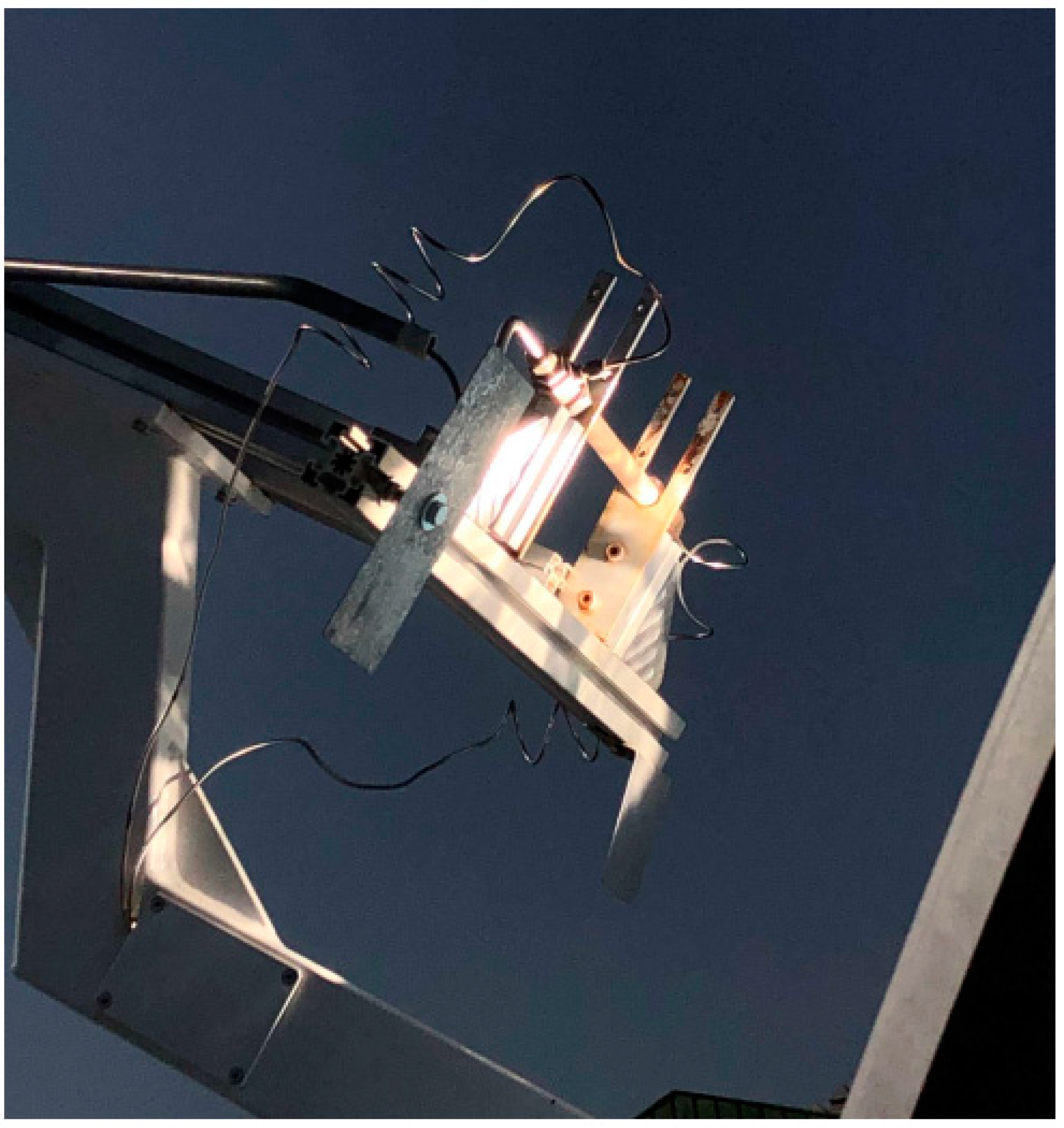
Figure 2.
Thermocouple T0 (type B) inside the receiver.
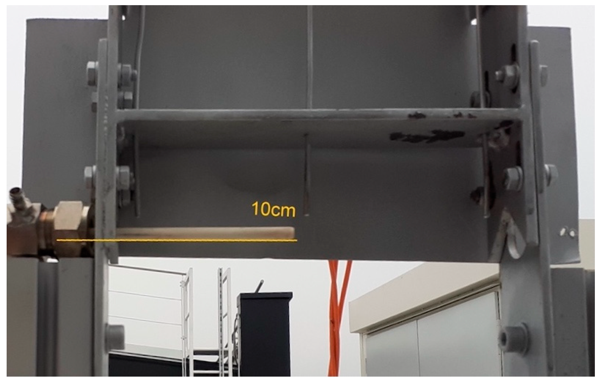
Figure 3.
Main geometrical parameters of the solar concentrator.
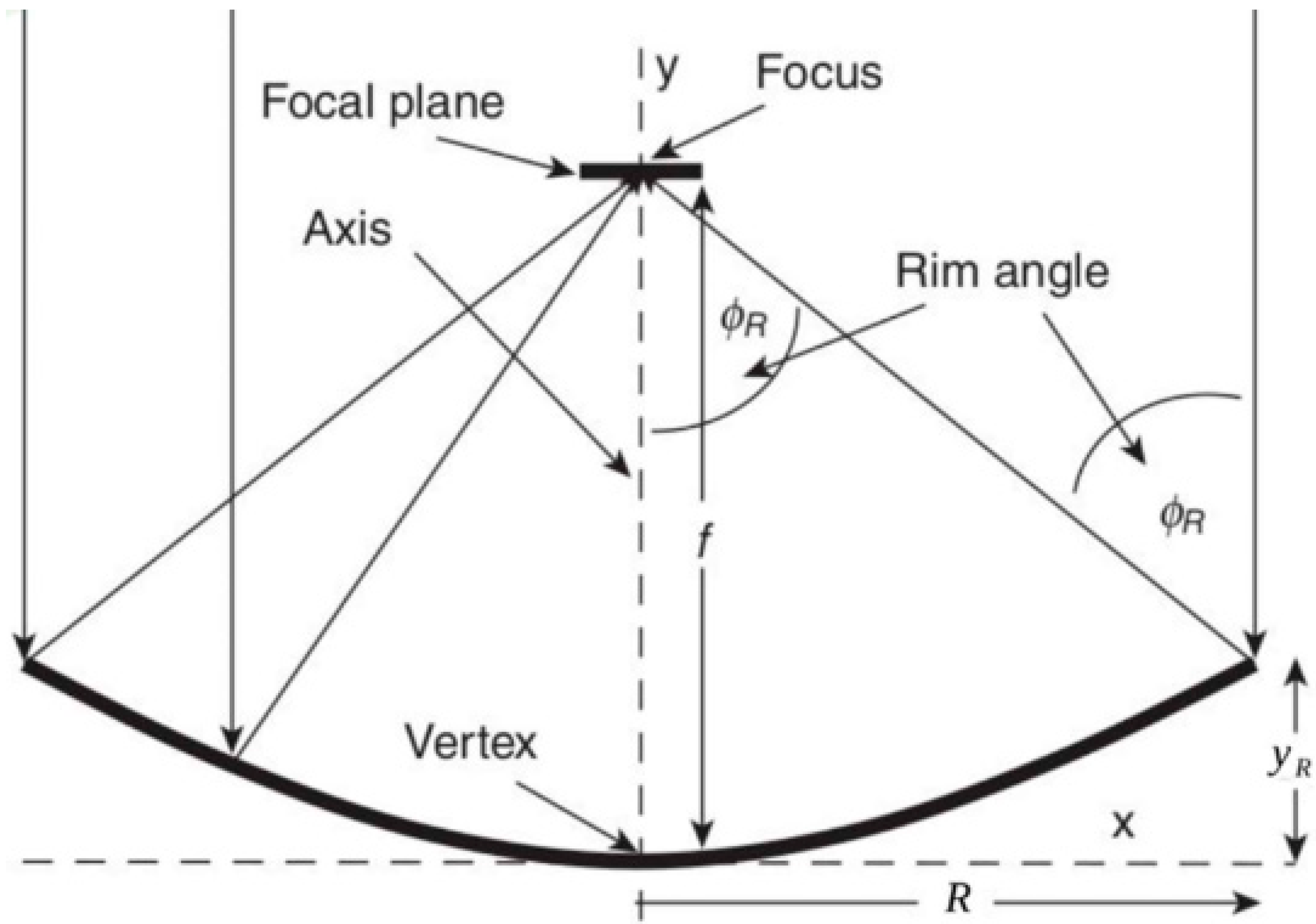
Figure 4.
Example of the temperature recorded in the central receiver point (T0) in March and April 2023.
Figure 4.
Example of the temperature recorded in the central receiver point (T0) in March and April 2023.
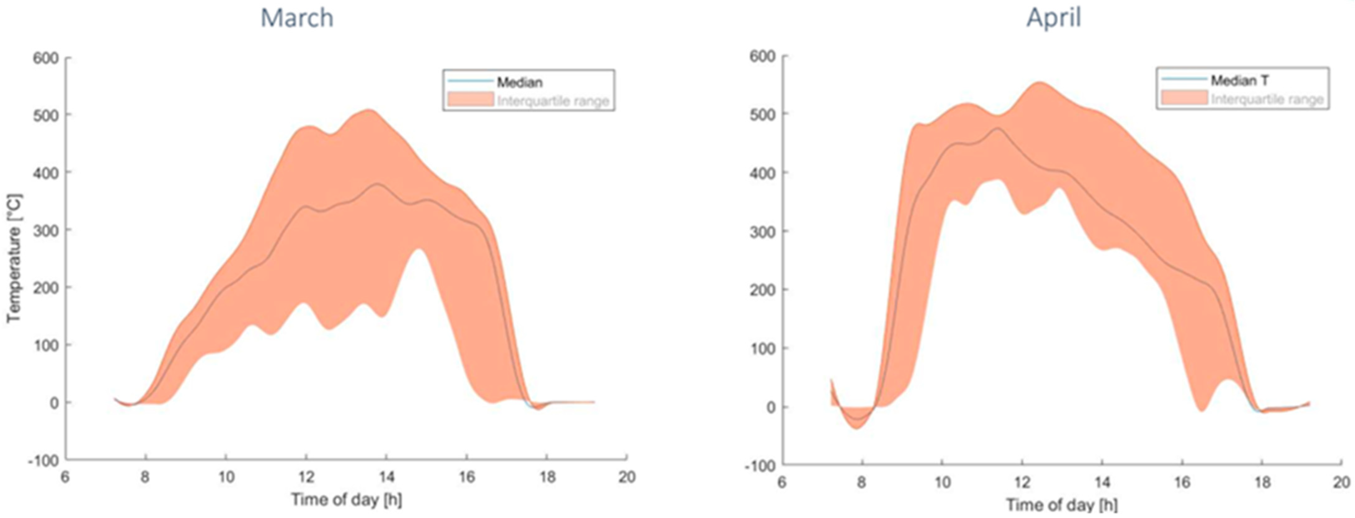
Figure 5.
Evaluation of the induced effort for the metallic alloys–thermal stress versus yield stress: (a) alloy 625, (b) alloy 800H, (c) Haynes 230, (d) Inconel 740H.
Figure 5.
Evaluation of the induced effort for the metallic alloys–thermal stress versus yield stress: (a) alloy 625, (b) alloy 800H, (c) Haynes 230, (d) Inconel 740H.
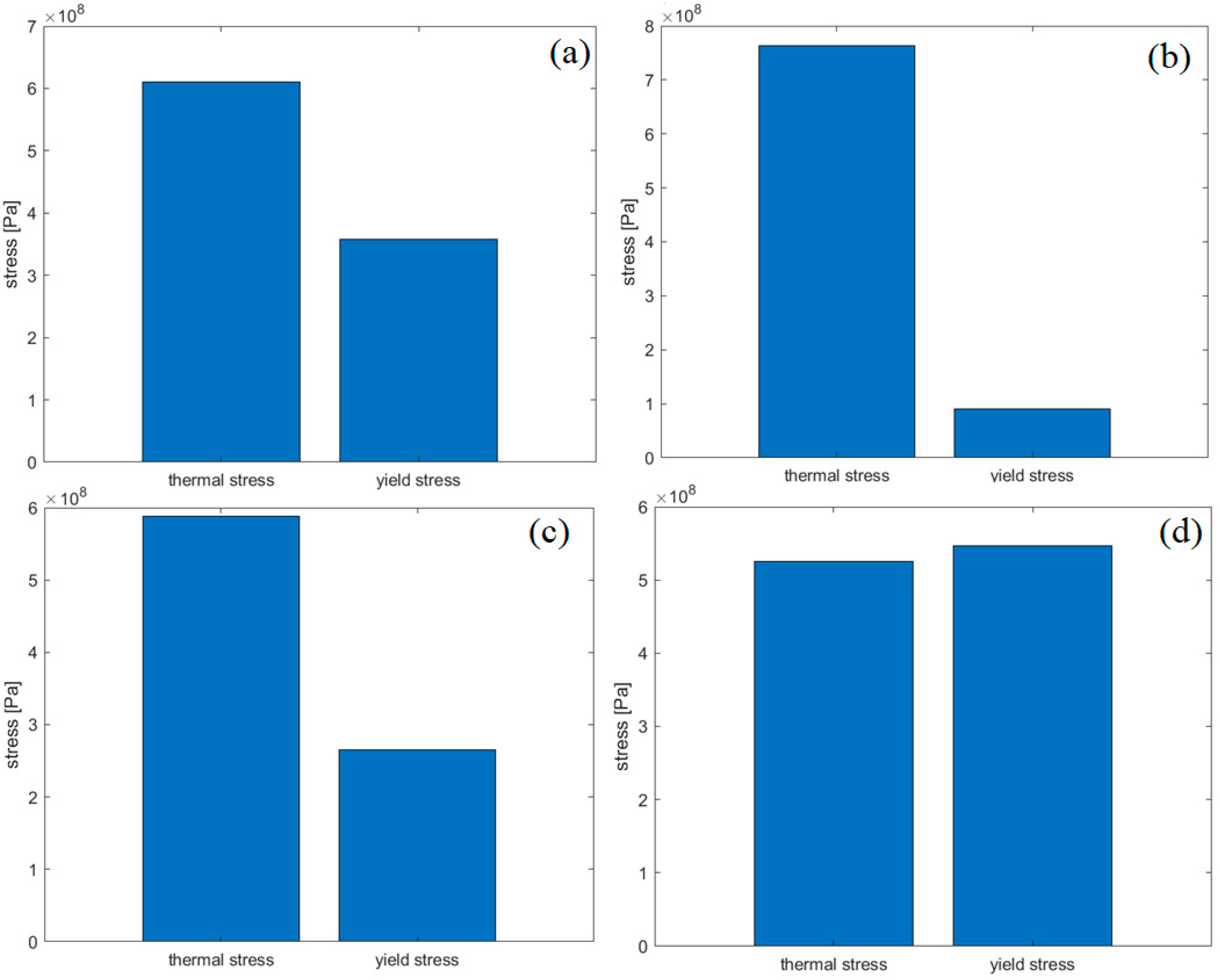
Figure 6.
Experimental activity for the metal alloys used (a) Inconel 740H; (b) alloy 625; (c) Haynes 230.
Figure 6.
Experimental activity for the metal alloys used (a) Inconel 740H; (b) alloy 625; (c) Haynes 230.


Table 1.
Geometrical data for the solar concentrator.
| Name | Expression | Value | Description |
|---|---|---|---|
| 0.92 m | Focal length | ||
| 45° | 0.7854 rad | Rim Angle | |
| - | 2.37 m | Diameter of the concentrator | |
| 2.54 m2 | Capturing Area of the concentrator | ||
| d | - | 18.06 × 10⁻³ m | Receiver diameter (outer) |
| L | - | 0.2 m | Receiver length |
| CR0 | - | 8013 | Optical concentration ratio |
| Inconel 740H | Alloy 625 | Alloy 800H | Haynes 230 | |
|---|---|---|---|---|
| T melting | 1288–1362 °C | 1290–1350 °C | 1357–1385 °C | 1301–1371 °C |
| Elastic modulus (E) | 186 GPa (@T = 600 °C) 178 GPa (@T = 700 °C) 169 GPa (@T = 800 °C) | 170 GPa (@T = 650 °C) 160 GPa (@T = 760 °C) 148 GPa (@T = 870 °C) | 157.7 GPa (@T = 600 °C) 150.1 GPa (@T = 700 °C) 141.3 GPa (@T = 800 °C) | 175 GPa (@T = 600 °C) 168 GPa (@T = 700 °C) 159 GPa (@T = 800 °C) |
| Yield strength () | 742 MPa (@Tamb) 608 Mpa (@T = 700 °C) 547 MPa (@T = 800 °C) | 414–517 MPa (annealed, @Tamb) 357.2 MPa (@T = 800 °C) | 150 MPa (@Tamb) 109 MPa (@T = 700 °C) 90 MPa (@T = 760 °C) | 415 MPa (@Tamb) 265 MPa (@871 °C) 294 Mpa (@T = 1000 °C) |
| Coefficient of linear expansion () | 15.7 | 15.5 | 18 | 15.3 |
| Density (ρ) | 8050 kg/ | 8422 kg/ | 7940 kg/m3 | 8968 kg/ |
| Specific heat (c) | 573 J/kgK | 600 J/kgK | 460 J/kgK | 465 J/kgK |
| Thermal conductivity (k) | 22.1 W/mK | 15.7 W/mK | 11.5 W/mK | 16.4 W/mK |
Table 3.
Biot number evaluated for all the materials.
| Material | Biot |
|---|---|
| Alloy 625 | 0.0019 |
| Alloy 800H | 0.0026 |
| Haynes 230 | 0.0018 |
| Inconel 740H | 0.0013 |
Disclaimer/Publisher’s Note: The statements, opinions and data contained in all publications are solely those of the individual author(s) and contributor(s) and not of MDPI and/or the editor(s). MDPI and/or the editor(s) disclaim responsibility for any injury to people or property resulting from any ideas, methods, instructions or products referred to in the content. |
© 2023 by the authors. Licensee MDPI, Basel, Switzerland. This article is an open access article distributed under the terms and conditions of the Creative Commons Attribution (CC BY) license (https://creativecommons.org/licenses/by/4.0/).
Share and Cite
MDPI and ACS Style
Perrero, M.; Papurello, D. Solar Disc Concentrator: Material Selection for the Receiver. Energies 2023, 16, 6870. https://doi.org/10.3390/en16196870
AMA Style
Perrero M, Papurello D. Solar Disc Concentrator: Material Selection for the Receiver. Energies. 2023; 16(19):6870. https://doi.org/10.3390/en16196870
Chicago/Turabian StylePerrero, Margherita, and Davide Papurello. 2023. "Solar Disc Concentrator: Material Selection for the Receiver" Energies 16, no. 19: 6870. https://doi.org/10.3390/en16196870
Note that from the first issue of 2016, this journal uses article numbers instead of page numbers. See further details here.