
Recent Developments in Cooling Systems and Cooling Management for Electric Motors
 ,
,  , ,
, ,
Abstract
:1. Introduction
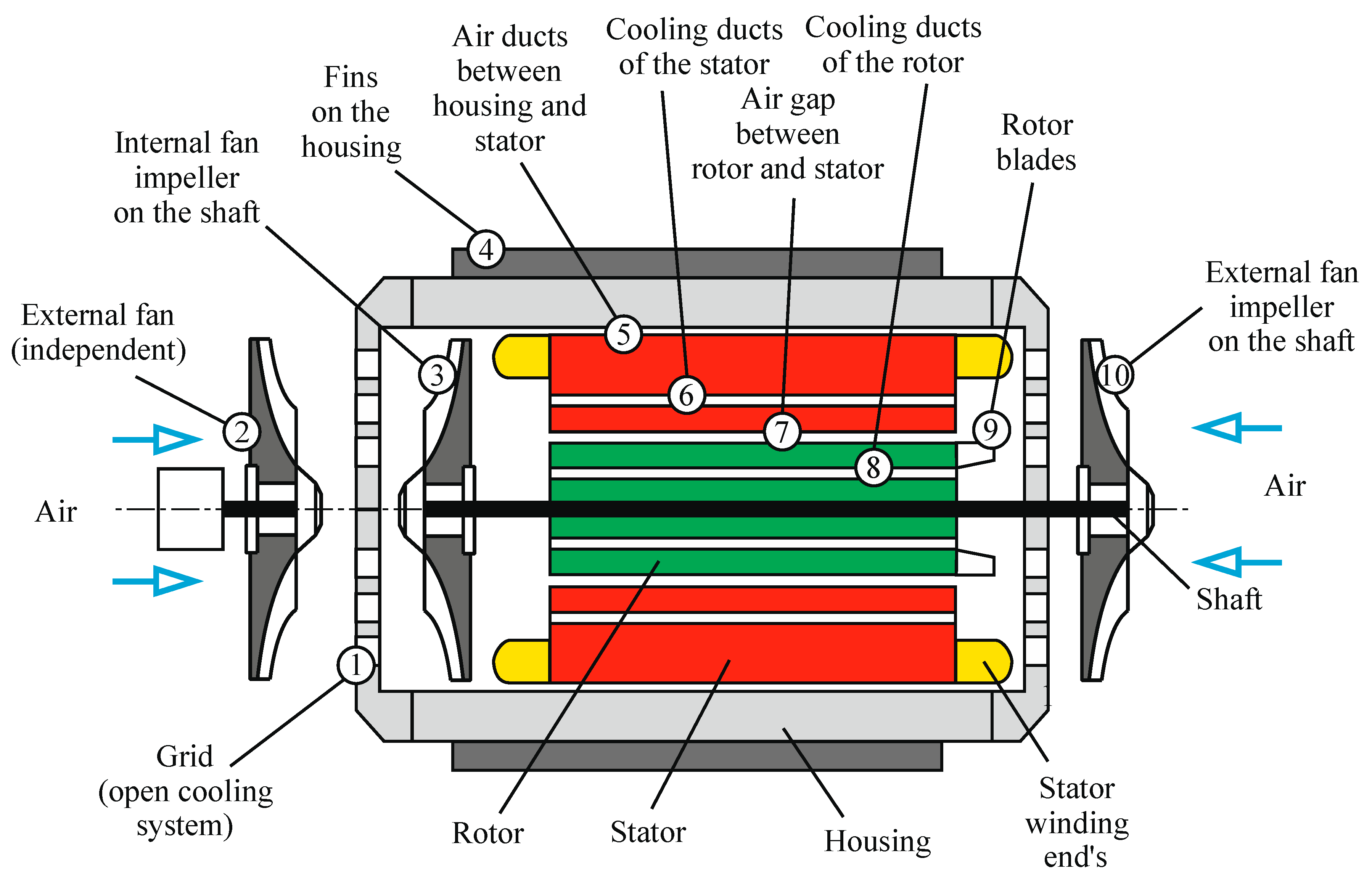
- Overview of the temperature distribution in the electric motor;
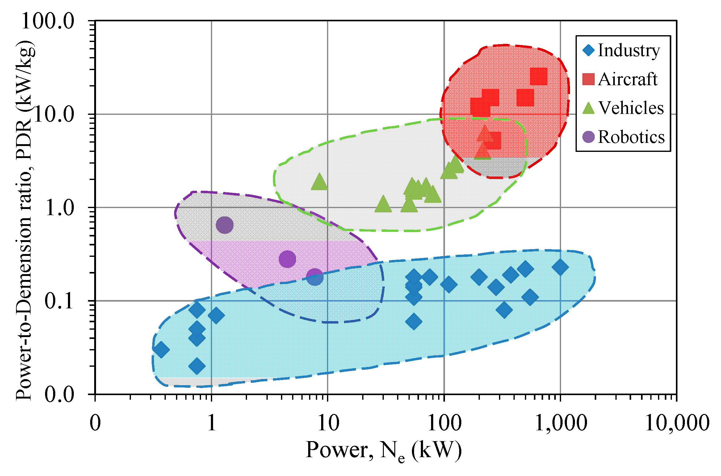
- Comparative overview of the influence of the temperature on electric motor performance, especially on the power-to-dimension ratio;
- Overview and discussion of cooling methods and systems, including patent analysis and recent trends.
2. Analysis of the Temperature Influence on the Performance of Electric Motors
2.1. The Temperature Distribution in Electric Motors
2.2. The Influence of Coolant Temperature on the Motor Power and Efficiency
3. Overview of the Cooling Methods of Electric Motors and Their Application in Different Areas
4. Overview of Principle Solutions for Cooling Electric Motors
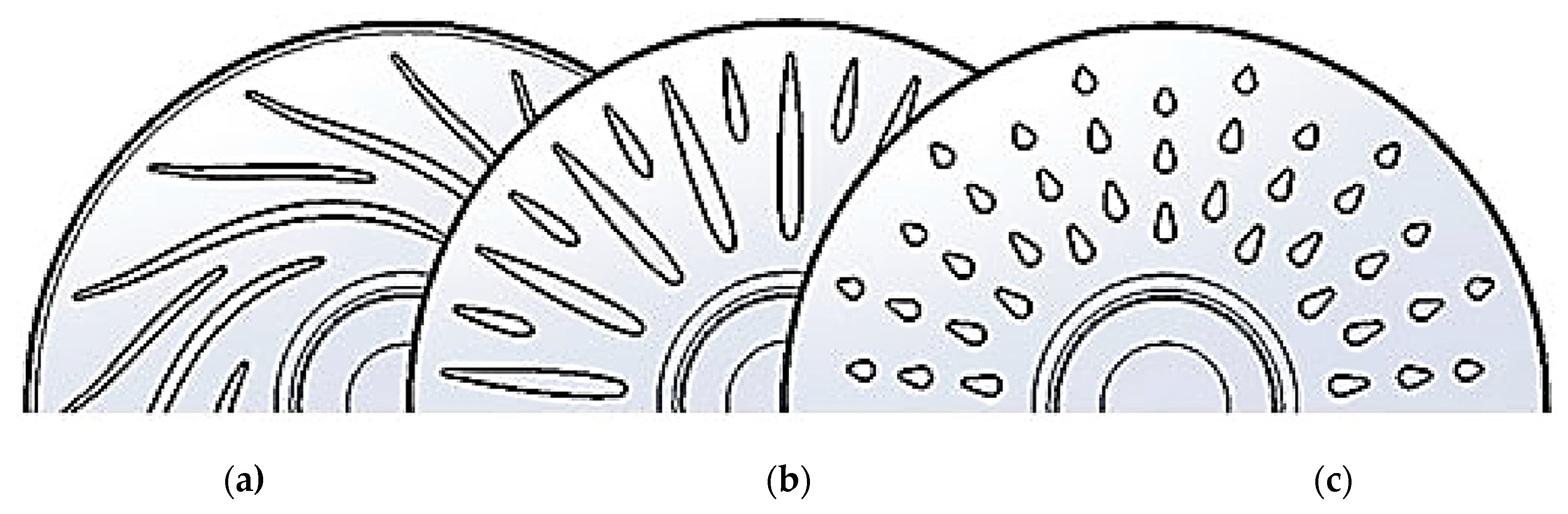
4.1. The Air Cooling System
4.2. Liquid Cooling Systems
4.3. Overview of Patents for Cooling of Electric Motors
4.4. The Cooling Systems Using Refrigerant
5. Conclusions
Author Contributions
Funding
Data Availability Statement
Conflicts of Interest
References
- Gronwald, P.O.; Kern, T.A. Traction Motor Cooling Systems: A Literature Review and Comparative Study. IEEE Trans. Transp. Electrif. 2021, 7, 2892–2913. [Google Scholar] [CrossRef]
- Carriero, A.; Locatelli, M.; Ramakrishnan, K.; Mastinu, G.; Gobbi, M. A Review of the State of the Art of Electric Traction Motors Cooling Techniques; SAE Technical Papers; SAE International: Warrendale, PA, USA, 2018. [Google Scholar]
- IEC 60034-1:2022; Rotating Electrical Machines—Part 1: Rating and Performance. International Electrotechnical Commission: Geneva, Switzerland, 2022; p. 161.
- Bonnett, A.H.; Soukup, G.C. Cause and Analysis of Stator and Rotor Failures in Three-Phase Squirrel-Cage Induction Motors. IEEE Trans. Ind. Appl. 1992, 28, 921–937. [Google Scholar] [CrossRef]
- Lipo, T. Introduction to AC Machine Design; IEEE: Piscataway, NJ, USA, 2018. [Google Scholar]
- Sustainable Development Goals (SDG17). Division for Sustainable Development Goals Department of Economic and Social Affairs United Nations Secretariat. Available online: https://sdgs.un.org/goals/goal17 (accessed on 2 February 2023).
- ABB. Low Voltage Motors. Motor Guide, 4th ed.; ABB: Zurich, Switzerland, 2019; p. 112. [Google Scholar]
- ABB. Low Voltage Process Performance Motors According to EU MEPS; ABB: Zurich, Switzerland, 2014; p. 124. [Google Scholar]
- Turncircles, s.r.o. Ultra Light Custom Electric Motor. Available online: https://turncircles.com/ (accessed on 7 October 2023).
- WEG. Specification of Electric Motors; WEG: Jaraguá do Sul, Brazil, 2020; p. 68. [Google Scholar]
- W22 Three-Phase Electric Motor; WEG: Jaraguá do Sul, Brazil, 2011; p. 44.
- Marathon Electric Motors. Commercial & Industrial Motor Solutions; Marathon Electric Motors: Eibergen, Netherlands, 2018; p. 318. [Google Scholar]
- Marathon Electric Motors. IEC IE3 Motor Range; Marathon Electric Motors: Eibergen, Netherlands, 2014; p. 20. [Google Scholar]
- SIMOTICS GP, SD, XP, DP Low-Voltage Motors, 12/2021 ed.; Siemens AG: Alpharetta, GA, USA; Erlangen, Germany, 2021; p. 706. Available online: https://support.industry.siemens.com/cs/document/109763390/catalog-d-81-2-usa-edition-2022?dti=0&pnid=13308&lc=en-NO" (accessed on 7 October 2023).
- SIMOTICS NEMA Motors. Low Voltage AC Motors Selection and Pricing Guide. Edition 2022 ed.; Siemens AG: Alpharetta, GA, USA, 2019; p. 293. Available online: https://support.industry.siemens.com/cs/document/109749197/catalog-d-81-1-simotics-gp-sd-xp-dp-low-voltage-motors-september-2023?dti=0&pnid=13308&lc=en-NO (accessed on 7 October 2023).
- Brook Cromoton. Series 10 IE3. Frame size 80 to 355; Brook Cromoton: West Yorkshire, UK, 2015; Volume 2.1, p. 22. Available online: http://www.brookcrompton.com/upload/20151E_Series10_IE3_issue_2_1.pdf (accessed on 7 October 2023).
- Brook Cromoton. Series 10. Frame size 56 to 450; Brook Cromoton: West Yorkshire, UK, 2012; Volume 2, p. 30. Available online: http://www.brookcrompton.com/upload/20121E_issue2_Series10.pdf (accessed on 7 October 2023).
- Brook Cromoton. W Cast Iron motors. Frame size 80 to 355, 08/16 ed.; Brook Cromoton: West Yorkshire, UK, 2011; Volume 4, p. 30. Available online: http://www.brookcrompton.com/upload/20113E_W_Cast_Iron_issue4.pdf (accessed on 7 October 2023).
- Schneider Electric. Catalog Lexium 32 Servo Drives BMH BSH Servo Motors: France, 2021. p. 61. Available online: https://www.se.com/ (accessed on 7 October 2023).
- Burress, T. Electrical Performance, Reliability Analysis, and Characterization; Project ID: EDT087; U.S. Department of Energy: Washington, DC, USA, 2017; p. 25. [Google Scholar]
- Burress, T.A.; Campbell, S.L.; Coomer, C.; Ayers, C.W.; Wereszczak, A.A.; Cunningham, J.P.; Marlino, L.D.; Seiber, L.E.; Lin, H.-T. Evaluation of the 2010 Toyota Prius Hybrid Synergy Drive System; Oak Ridge National Lab. (ORNL): Oak Ridge, TN, USA; Power Electronics and Electric Machinery Research Facility: Oak Ridge, TN, USA, 2011; p. 88. [Google Scholar]
- Gai, Y.; Kimiabeigi, M.; Chuan Chong, Y.; Widmer, J.D.; Deng, X.; Popescu, M.; Goss, J.; Staton, D.A.; Steven, A. Cooling of automotive traction motors: Schemes, examples, and computation methods. IEEE Trans. Ind. Electron. 2019, 66, 1681–1692. [Google Scholar] [CrossRef]
- Burress, T. Benchmarking State-of-the-Art Technologies; Project ID: APE006; US DOE Hydrogen and Fuel Cells Program and Vehicle Technologies Program Annual Merit Review and Peer Evaluation Meeting: Oak Ridge, TN, USA, 2013; p. 21. [Google Scholar]
- Limited, I.P. Electric Powertrain. Available online: https://ehelix.com/electric-powertrains/ (accessed on 7 October 2023).
- EMRAX. EMRAX 268 Technical Data. Available online: https://emrax.com/e-motors/emrax-268/#1482059435741-232ed37a-accc (accessed on 7 October 2023).
- H.X.T., Inc. High Performance Electric Propulsion Systems. Available online: https://www.h3x.tech/ (accessed on 7 October 2023).
- Frank, A. eAircraft: Hybrid-elektrische Antriebe für Luftfahrzeuge. In Proceedings of the 14 Tag der Deutschen Luft- und Raumfahrtregionen, Potsdam, Germany, 10 September 2019; p. 37. [Google Scholar]
- Wrobel, R. A technology overview of thermal management of integrated motor drives—Electrical Machines. Therm. Sci. Eng. Prog. 2022, 29, 101222. [Google Scholar] [CrossRef]
- Ponomarev, P.; Polikarpova, M.; Pyrhönen, J. Thermal modeling of directly-oil-cooled permanent magnet synchronous machine. In Proceedings of the 2012 20th International Conference on Electrical Machines, ICEM 2012, Marseille, France, 2–5 September 2012; pp. 1882–1887. [Google Scholar]
- Sikora, M.; Vlach, R.; Navrátil, P. The unusial water cooling applied on small asynchronous motor. Eng. Mech. 2011, 18, 143–153. [Google Scholar]
- Chong, Y.C. Thermal Analysis and Air Flow Modelling of Electrical Machines. Ph.D. Thesis, The University of Edinburgh, Edinburgh, UK, 2015. [Google Scholar]
- Stone, G.C.; Culbert, I.; Boulter, E.A.; Dhirani, H. Electrical Insulation for Rotating Machines: Design, Evaluation, Aging, Testing, and Repair, 2nd ed.; IEEE: Piscataway, NJ, USA, 2014; Volume 9781118057063, pp. 1–643. [Google Scholar]
- Toliyat, H.A.; Kliman, G.B. Handbook of Electric Motors, 2nd ed.; Marcel Dekker: New York, NY, USA, 2004; Volume 120. [Google Scholar]
- IEC 60034-6: 1991; Rotating electrical machines—Part 6: Methods of Cooling (IC Code). International Electrotechnical Commission: Geneva, Switzerland, 1991; p. 39.
- Kral, C.; Haumer, A.; Bäuml, T. Thermal model and behavior of a totally-enclosed-water-cooled squirrel-cage induction machine for traction applications. IEEE Trans. Ind. Electron. 2008, 55, 3555–3565. [Google Scholar] [CrossRef]
- Yung, C. Cool Facts About Cooling Electric Motors: Improvements in Applications That Fall Outside the Normal Operating Conditions. IEEE Ind. Appl. Mag. 2015, 21, 47–56. [Google Scholar] [CrossRef]
- Three-Phase Asynchronous Motors; ABB Technical Application Papers No. 7; Generalities and ABB Proposals for the Coordination of Protective Devices; ABB: Bergamo, Italy, 2008; p. 48.
- Bharat Bijlee. Low Voltage Motors; Bharat Bijlee: Mumbai, India, 2016; p. 86. [Google Scholar]
- Qandil, M.M.; Ray, R.B. Immersible Motor System. U.S. Patent US6183208, 6 February 2001. [Google Scholar]
- Kanei, N.; Haga, S.; Horiuchi, K.; Sonoyama, K. Totally Enclosed Fan Cooled Motor. U.S. Patent US7629717B2, 8 December 2009. [Google Scholar]
- Ulbrich, S.; Kopte, J.; Proske, J. Cooling fin optimization on a TEFC electrical machine housing using a 2-D conjugate heat transfer model. IEEE Trans. Ind. Electron. 2018, 65, 1711–1718. [Google Scholar] [CrossRef]
- Staton, D.A.; Cavagnino, A. Convection heat transfer and flow calculations suitable for electric machines thermal models. IEEE Trans. Ind. Electron. 2008, 55, 3509–3516. [Google Scholar] [CrossRef]
- Gilson, G.M.; Raminosoa, T.; Pickering, S.J.; Gerada, C.; Hann, D.B. A combined electromagnetic and thermal optimisation of an aerospace electric motor. In Proceedings of the 19th International Conference on Electrical Machines, ICEM 2010, Rome, Italy, 6–8 September 2010. [Google Scholar]
- Valenzuela, M.A.; Tapia, J.A. Heat transfer and thermal design of finned frames for TEFC variable-speed motors. IEEE Trans. Ind. Electron. 2008, 55, 3500–3508. [Google Scholar] [CrossRef]
- Güvenç, A.; Yüncü, H. An experimental investigation on performance of fins on a horizontal base in free convection heat transfer. Heat Mass Transf. 2001, 37, 409–416. [Google Scholar] [CrossRef]
- Albers, T.; Bonnett, A.H. Motor temperature considerations for pulp and paper mill applications. IEEE Trans. Ind. Appl. 2002, 38, 1701–1713. [Google Scholar] [CrossRef]
- Bante, K.G.; Tarnekar, S.G.; Tutakane, D.R. AC Motor cooling system Analysis Based on Application Case Study. Int. J. Eng. Invent. 2013, 2, 9–15. [Google Scholar]
- Bonnett, A.H. Operating temperature considerations and performance characteristics for IEEE 841 motors. IEEE Trans. Ind. Appl. 2001, 37, 1120–1131. [Google Scholar] [CrossRef]
- Morel, L.; Raguideau, J.-L.; Raguin, B. Ventilation Device and Rail Traction Electric Motor Equipped wth Such a Device. U.S. Patent US6570276, 27 March 2003. [Google Scholar]
- Early, J.; Evon, T.S.; Grant, E.D.; Melfi, M.J.; Smith, P.L.; Stelzner, D.J. Electric Motor Having Frame Adaptable for Enclosed and Open Motor Cooling. U.S. Patent US5998896, 7 December 1999. [Google Scholar]
- Metheny, L.; Sudhoff, D.; Thompson, A.; Budzynski, R. Integrated electric Motor and Drive System with Auxiliary Cooling Motor and Asymivietric Heat Sink. U.S. Patent US5763969, 9 June 1998. [Google Scholar]
- Lenz, H.G. Castable Rotor Having Radially Venting Laminations. U.S. Patent US3684906, 15 August 1972. [Google Scholar]
- Lukens, A.F. Heat Transfer System for Dynamo-Electric Machine. U.S. Patent US3725706, 3 April 1973. [Google Scholar]
- Baumann, F.; Rosenberry, G. Ventilated Dynamoelectric Machines. U.S. Patent US3749953, 31 July 1973. [Google Scholar]
- Nakahama, T.; Biswas, D.; Kawano, K.; Ishibashi, F. Improved cooling performance of large motors using fans. IEEE Trans. Energy Convers. 2006, 21, 324–331. [Google Scholar] [CrossRef]
- Nakahama, T.; Ishibashi, F.; Sato, K.; Kawano, K. Effects of fan blade forward-swept and inclined amounts in electric motors. IEEE Trans. Energy Convers. 2010, 25, 457–464. [Google Scholar] [CrossRef]
- Cezário, C.A.; Oliveira, A.A.M. Electric motor internal fan system CFD validation. In Proceedings of the 2008 International Conference on Electrical Machines, ICEM’08, Vilamoura, Portugal, 6–9 September 2008. [Google Scholar]
- Kung, L.; Bikle, U.; Popp, O.; Jakoby, R. Improvement of the cooling performance of symmetrically self-ventilated induction machines in the 2–15 MW range. In Proceedings of the IEMDC 2001—IEEE International Electric Machines and Drives Conference, Cambridge, MA, USA, 17–20 June 2001; pp. 673–680. [Google Scholar]
- Mizuno, S.; Noda, S.; Matsushita, M.; Koyama, T.; Shiraishi, S. Development of a totally enclosed fan-cooled traction motor. IEEE Trans. Ind. Appl. 2013, 49, 1508–1514. [Google Scholar] [CrossRef]
- Fawzal, A.S.; Cirstea, R.M.; Gyftakis, K.N.; Woolmer, T.J.; Dickison, M.; Blundell, M. Fan Performance Analysis for Rotor Cooling of Axial Flux Permanent Magnet Machines. IEEE Trans. Ind. Appl. 2017, 53, 3295–3304. [Google Scholar] [CrossRef]
- Rao, G.V.R.S.; Rao, D.V.V.S. Design of cooling fan for noise reduction using CFD. Int. J. Sci. Eng. Res. 2011, 2, 1–5. [Google Scholar]
- Kindl, V.; Pechanek, R.; Bouzek, L. Cooling of new designed machine. In Proceedings of the 13th International Symposium on Mechatronics, MECHATRONIKA 2010, Trencianske Teplice, Slovakia, 2–4 June 2010; pp. 95–98. [Google Scholar]
- Glahn, A.; Baumgartner, J.; Jung, M. Generatorkühlung mit Kühlernachlaufmischung. Patent EU EP1006643A3, 29 January 2003. [Google Scholar]
- Matsubara, M.; Yasuo, H.; Takashi, H.; Motoyasu, M. Cooling Structure for Rotor Core in Electric Rotating Machine. U.S. Patent US8080908, 20 December 2011. [Google Scholar]
- Schmidt, V. Electric Machine with Rotor Cooling and Corresponding Cooling Method. U.S. Patent US7646119B2, 12 January 2010. [Google Scholar]
- Hall, J.A. Self-Cooled for an Electrical Machine. U.S. Patent US7514827B2, 7 April 2009. [Google Scholar]
- Kylander, G.; Leijon, M. Axial Cooling of a Rotor. U.S. Patent US6369470B1, 6 April 2002. [Google Scholar]
- Arbanas, V.; Zysset, E. Driving unit Including a Liquid Cooled Electric Motor and a Planetary Gear. U.S. Patent US6329731, 11 December 2001. [Google Scholar]
- Masahiro Hasebe, Y. Motor Cooling Circuit. U.S. Patent US5889342, 30 March 1999. [Google Scholar]
- Armor, A.; Morgan, J. Flexible Serrated Abradable Stator Mounted Air Gap Baffle for a Dynamoelectric Machine. U.S. Patent US4264834, 28 April 1981. [Google Scholar]
- Wieland, H. External Rotor Motor Having a Cooling System. U.S. Patent US4574210, 4 March 1986. [Google Scholar]
- Johnsen, T.A. Cooling of a Rotor for a Rotary Electric Machine. U.S. Patent US6727609B2, 27 April 2004. [Google Scholar]
- Baumgartner, J. Generatorkühlung mit Kühlernachlaufmischung. EU Patent EP1006643A2, 7 June 2000. [Google Scholar]
- Nagayama, T.; Kitamura, M.; Shiraishi, S. Fully-Enclosed Fan-Cooled Motor. U.S. Patent US7462964, 9 December 2008. [Google Scholar]
- VanLuik, R.; Prosser, E.; Deitt, E. Semi-Enclosed AC Motor. U.S. Patent US7459817, 2 December 2008. [Google Scholar]
- Lu, Q.; Zhang, X.; Chen, Y.; Huang, X.; Ye, Y.; Zhu, Z.Q. Modeling and Investigation of Thermal Characteristics of a Water-Cooled Permanent-Magnet Linear Motor. IEEE Trans. Ind. Appl. 2015, 51, 2086–2096. [Google Scholar] [CrossRef]
- Zysset, E. Liquid Cooled Asynchronous Electric Machine. U.S. Patent US6191511B1, 20 February 2001. [Google Scholar]
- RD 34.45.507; Model Guidelines for Operation of Large Electric Motors with Water Cooling of Rotor for Feed Pump Drives. Soyuztechenergo: Moscow, Russia, 1989; p. 41.
- Onjanow, N. Dynamoelectric Machine with Improved. U.S. Patent US3610975, 5 October 1971. [Google Scholar]
- Arbab, N.; Wang, W.; Lin, C.; Hearron, J.; Fahimi, B. Thermal Modeling and Analysis of a Double-Stator Switched Reluctance Motor. IEEE Trans. Energy Convers. 2015, 30, 1209–1217. [Google Scholar] [CrossRef]
- Tüysüz, A.; Meyer, F.; Steichen, M.; Zwyssig, C.; Kolar, J.W. Advanced Cooling Methods for High-Speed Electrical Machines. IEEE Trans. Ind. Appl. 2017, 53, 2077–2087. [Google Scholar] [CrossRef]
- Lehmann, R.; Künzler, M.; Moullion, M.; Gauterin, F. Comparison of Commonly Used Cooling Concepts for Electrical Machines in Automotive Applications. Machines 2022, 10, 442. [Google Scholar] [CrossRef]
- Campbell, J.B.; Tolbert, L.M.; Ayers, C.W.; Ozpineci, B.; Lowe, K.T. Two-phase cooling method using the R134a refrigerant to cool power electronic devices. IEEE Trans. Ind. Appl. 2007, 43, 648–656. [Google Scholar] [CrossRef]
- Deisenroth, D.C.; Ohadi, M. Thermal management of high-power density electric motors for electrification of aviation and beyond. Energies 2019, 12, 3594. [Google Scholar] [CrossRef]
- Zhenguo, L.; Lin, R. Optimization design of the spray evaporative-cooling large electrical machine. In Proceedings of the 19th International Conference on Electrical Machines and Systems, ICEMS 2016, Chiba, Japan, 13–16 November 2016. [Google Scholar]
- Li, Z.; Ruan, L.; Tang, L. Heat transfer characteristics of spray evaporative cooling system for large electrical machines. In Proceedings of the 2015 18th International Conference on Electrical Machines and Systems, ICEMS 2015, Pattaya, Thailand, 25–28 October 2015; pp. 1740–1743. [Google Scholar]
- Li, Z.; Fu, D.; Guo, J.; Gu, G.; Xiong, B. Study on spraying evaporative cooling technology for the large electrical machine. In Proceedings of the 12th International Conference on Electrical Machines and Systems, ICEMS 2009, Tokyo, Japan, 15–18 November 2009. [Google Scholar]
- Mount, G.; Endress, J. Refrigerant Cooling System for Electric Motor. U.S. Patent US3645112, 29 February 1972. [Google Scholar]
- Nakahama, T.; Suzuki, K.; Hashidume, S.; Ishihashi, F.; Hirata, M. Cooling airflow in unidirectional ventilated open-type motor for electric vehicles. IEEE Trans. Energy Convers. 2006, 21, 645–651. [Google Scholar] [CrossRef]
- Dames, M.; Ballmann, J.M.; Cruce, P.; Fee, D. Liqiuid Cooled Permanent Magnet Rotor. U.S. Patent US8022582B2, 20 September 2011. [Google Scholar]
- Iund, T.N.; Wookey, R.; Dames, M. Electrical Machine Having a Liquid-Cooled Rotor. U.S. Patent US7834492B2, 16 November 2010. [Google Scholar]
- Chai, F.; Tang, Y.; Pei, Y.; Liang, P.; Gao, H. Temperature field accurate modeling and cooling performance evaluation of direct-drive outer-rotor air-cooling in-wheel motor. Energies 2016, 9, 818. [Google Scholar] [CrossRef]
- Dorrell, D.G.; Hsieh, M.F.; Popescu, M.; Evans, L.; Staton, D.A.; Grout, V. A review of the design issues and techniques for radial-flux brushless surface and internal rare-earth permanent-magnet motors. IEEE Trans. Ind. Electron. 2011, 58, 3741–3757. [Google Scholar] [CrossRef]
- Kimiabeigi, M.; Long, R.; Widmer, J.D.; Gao, Y. Comparative Assessment of Single Piece and Fir-Tree-Based Spoke Type Rotor Designs for Low-Cost Electric Vehicle Application. IEEE Trans. Energy Convers. 2017, 32, 486–494. [Google Scholar] [CrossRef]
- Sindjui, R.; Zito, G.; Zhang, S. Experimental Study of Systems and Oils for Direct Cooling of Electrical Machine. J. Therm. Sci. Eng. Appl. 2022, 14, 051007. [Google Scholar] [CrossRef]
- Popescu, M.; Staton, D.A.; Boglietti, A.; Cavagnino, A.; Hawkins, D.; Goss, J. Modern Heat Extraction Systems for Power Traction Machines—A Review. IEEE Trans. Ind. Appl. 2016, 52, 2167–2175. [Google Scholar] [CrossRef]
- Jiang, W.; Jahns, T.M. Coupled Electromagnetic-Thermal Analysis of Electric Machines Including Transient Operation Based on Finite-Element Techniques. IEEE Trans. Ind. Appl. 2015, 51, 1880–1889. [Google Scholar] [CrossRef]
- Caricchi, F.; Crescimbini, F.; Di Napoli, A.; Marcheggiani, M. Prototype of electric vehicle drive with twin water-cooled wheel direct drive motors. In Proceedings of the PESC Record—IEEE Annual Power Electronics Specialists Conference, Baveno, Italy, 23–27 June 1996; pp. 1926–1932. [Google Scholar]
- Sano, S.; Yashiro, T.; Takizawa, K.; Mizutani, T. Development of new motor for compact-class hybrid vehicles. World Electr. Veh. J. 2016, 8, 443–449. [Google Scholar] [CrossRef]
- Polikarpova, M. Liquid Cooling Solutions for Rotating Permanent Magnet Synchronous Machines. Ph.D. Thesis, Lappeenranta University of Technology, Lappeenranta, Finland, 2014. [Google Scholar]
- Hari, D.; Brace, C.; Vagg, C.; Akehurst, S.; Ash, L.; Strong, R. Development and Testing of a Low Cost High Performance Hybrid Vehicle Electric Motor; SAE Technical Papers; SAE International: Warrendale, PA, USA, 2013. [Google Scholar]
- Bennion, K. Electric Motor Thermal Management R&D; National Renewable Energy Laboratory: Golden, CO, USA, 2016; p. 15. [Google Scholar]
- Zhu, G.; Jia, N.; Li, L.; Liu, T.; Xue, M.; Li, M. Cooling System Design Optimization of a High Power Density PM Traction Motor for Electric Vehicle Applications. J. Electr. Eng. Technol. 2021, 16, 3061–3068. [Google Scholar] [CrossRef]
- Pechanek, R.; Bouzek, L. Analyzing of two types water cooling electric motors using computational fluid dynamics. In Proceedings of the 15th International Power Electronics and Motion Control Conference and Exposition, EPE-PEMC 2012 ECCE Europe, Novi Sad, Serbia, 4–6 September 2012; pp. LS2e.41–LS42e.45. [Google Scholar]
- Zhang, B.; Qu, R.; Wang, J.; Xu, W.; Fan, X.; Chen, Y. Thermal Model of Totally Enclosed Water-Cooled Permanent-Magnet Synchronous Machines for Electric Vehicle Application. IEEE Trans. Ind. Appl. 2015, 51, 3020–3029. [Google Scholar] [CrossRef]
- Kulkarni, D.P.; Rupertus, G.; Chen, E. Experimental investigation of contact resistance for water cooled jacket for electric motors and generators. IEEE Trans. Energy Convers. 2012, 27, 204–210. [Google Scholar] [CrossRef]
- Funieru, B.; Binder, A. Thermal design of a permanent magnet motor used for gearless railway traction. In Proceedings of the 2008 34th Annual Conference of IEEE Industrial Electronics, Orlando, FL, USA, 10–13 November 2008; pp. 2061–2066. [Google Scholar]
- Zhang, X.; Wang, H.; Zhang, G.; Gu, G. Temperature characteristics in the stator model of a permanent magnet motor by water-cooling and evaporative cooling. In Proceedings of the ICEMS 2005 8th International Conference on Electrical Machines and Systems, Nanjing, China, 27–29 September 2005; pp. 2408–2410. [Google Scholar]
- El-Refaie, A.M.; Alexander, J.P.; Galioto, S.; Reddy, P.B.; Huh, K.K.; De Bock, P.; Shen, X. Advanced high-power-density interior permanent magnet motor for traction applications. IEEE Trans. Ind. Appl. 2014, 50, 3235–3248. [Google Scholar] [CrossRef]
- Schiefer, M.; Doppelbauer, M. Indirect slot cooling for high-power-density machines with concentrated winding. In Proceedings of the 2015 IEEE International Electric Machines and Drives Conference, IEMDC 2015, Coeur d’Alene, ID, USA, 10–13 May 2015; pp. 1820–1825. [Google Scholar]
- Rhebergen, C.; Bilgin, B.; Emadi, A.; Rowan, E.; Lo, J. Enhancement of electric motor thermal management through axial cooling methods: A materials approach. In Proceedings of the 2015 IEEE Energy Conversion Congress and Exposition, ECCE 2015, Montreal, ON, Canada, 20–24 September 2015; pp. 5682–5688. [Google Scholar]
- Madonna, V.; Giangrande, P.; Walker, A.; Galea, M. On the Effects of Advanced End-Winding Cooling on the Design and Performance of Electrical Machines. In Proceedings of the 2018 23rd International Conference on Electrical Machines, ICEM 2018, Alexandroupoli, Greece, 3–6 September 2018; pp. 311–317. [Google Scholar]
- Sixel, W.; Liu, M.; Nellis, G.; Sarlioglu, B. Cooling of Windings in Electric Machines via 3-D Printed Heat Exchanger. IEEE Trans. Ind. Appl. 2020, 56, 4718–4726. [Google Scholar] [CrossRef]
- Thomas, R.; Garbuio, L.; Gerbaud, L.; Chazal, H. Modeling and design analysis of the Tesla Model S induction motor. In Proceedings of the 2020 International Conference on Electrical Machines, ICEM 2020, Gothenburg, Sweden, 23–26 August 2020; pp. 495–501. [Google Scholar]
- Huang, Z.; Nategh, S.; Lassila, V.; Alaküla, M.; Yuan, J. Direct oil cooling of traction motors in hybrid drives. In Proceedings of the 2012 IEEE International Electric Vehicle Conference, IEVC 2012, Greenville, SC, USA, 4–8 March 2012. [Google Scholar]
- Davin, T.; Pellé, J.; Harmand, S.; Yu, R. Experimental study of oil cooling systems for electric motors. Appl. Therm. Eng. 2015, 75, 1–13. [Google Scholar] [CrossRef]
- Ghahfarokhi, P.S.; Podgornovs, A.; Kallaste, A.; Marques Cardoso, A.J.; Belahcen, A.; Vaimann, T. The Oil Spray Cooling System of Automotive Traction Motors: The State of the Art. IEEE Trans. Transp. Electrif. 2022, 9, 428–451. [Google Scholar] [CrossRef]
- Ghahfarokhi, P.S.; Podgornovs, A.; Kallaste, A.; Vaimann, T.; Belahcen, A.; Cardoso, A.J.M. Oil Spray Cooling with Hairpin Windings in High-Performance Electric Vehicle Motors. In Proceedings of the 2021 28th International Workshop on Electric Drives: Improving Reliability of Electric Drives, IWED 2021, Moscow, Russia, 27–29 January 2021. [Google Scholar]
- Bennion, K. Electric Motor Thermal Management R&D; NREL/PR-5400-63004; National Renewable Energy Lab. (NREL): Golden, CO, USA, 2021; p. 28. [Google Scholar]
- Liu, C.; Gerada, D.; Xu, Z.; Chong, Y.C.; Michon, M.; Goss, J.; Li, J.; Gerada, C.; Zhang, H. Estimation of Oil Spray Cooling Heat Transfer Coefficients on Hairpin Windings with Reduced-Parameter Models. IEEE Trans. Transp. Electrif. 2021, 7, 793–803. [Google Scholar] [CrossRef]
- Ludois, D.C.; Brown, I. Brushless and Permanent Magnet Free Wound Field Synchronous Motors for EV Traction; DE-EE0006849; University of Wisconsin: Madison, WI, USA; Illinois Institute of Technology: Chicago, IL, USA, 2017; p. 51. [Google Scholar]
- Liu, C.; Xu, Z.; Gerada, D.; Li, J.; Gerada, C.; Chong, Y.C.; Popescu, M.; Goss, J.; Staton, D.; Zhang, H. Experimental Investigation on Oil Spray Cooling with Hairpin Windings. IEEE Trans. Ind. Electron. 2020, 67, 7343–7353. [Google Scholar] [CrossRef]
- Acquaviva, A.; Skoog, S.; Grunditz, E.; Thiringer, T. Electromagnetic and Calorimetric Validation of a Direct Oil Cooled Tooth Coil Winding PM Machine for Traction Application. Energies 2020, 13, 3339. [Google Scholar] [CrossRef]
- Liu, C.; Chong, Y.C.; Michon, M.; Goss, J.; Gerada, D.; Xu, Z.; Gerada, C.; Zhang, H. Model Calibration of Oil Jet and Oil Spray Cooling in Electrical Machines with Hairpin Windings. In Proceedings of the 2021 IEEE Energy Conversion Congress and Exposition, ECCE 2021, Vancouver, BC, Canada, 10–14 October 2021; pp. 3813–3820. [Google Scholar]
- Park, M.H.; Kim, S.C. Thermal characteristics and effects of oil spray cooling on in-wheel motors in electric vehicles. Appl. Therm. Eng. 2019, 152, 582–593. [Google Scholar] [CrossRef]
- Camilleri, R.; McCulloch, M. Investigation of an Integrated Evaporative Cooling Mechanism for an Outer-Rotor Permanent Magnet Machine. Heat Transf. Eng. 2014, 36, 1192–1202. [Google Scholar] [CrossRef]
- Nategh, S.; Huang, Z.; Krings, A.; Wallmark, O.; Leksell, M. Thermal modeling of directly cooled electric machines using lumped parameter and limited cfd analysis. IEEE Trans. Energy Convers. 2013, 28, 979–990. [Google Scholar] [CrossRef]
- Mudawar, I.; Bharathan, D.; Kelly, K.; Narumanchi, S. Two-phase spray cooling of hybrid vehicle electronics. IEEE Trans. Compon. Packag. Technol. 2009, 32, 501–512. [Google Scholar] [CrossRef]
- Nategh, S.; Boglietti, A.; Liu, Y.; Barber, D.; Brammer, R.; Lindberg, D.; Aglen, O. A Review on Different Aspects of Traction Motor Design for Railway Applications. IEEE Trans. Ind. Appl. 2020, 56, 2148–2157. [Google Scholar] [CrossRef]
- Norwegian Electric System. Motors: Double Jacket Water Cooled Motors; Norwegian Electric System: Bergen, Norway, 2017; p. 4. [Google Scholar]
- Wang, J.X.; Li, Y.Z.; Yu, X.K.; Li, G.C.; Ji, X.Y. Investigation of heat transfer mechanism of low environmental pressure large-space spray cooling for near-space flight systems. Int. J. Heat Mass Transf. 2018, 119, 496–507. [Google Scholar] [CrossRef]
- Maeda, K.; Fujiwara, S.; Mochizuki, T.; Nagashima, Y. Motor Cooling Apparatus for Refrigerator. U.S. Patent US4669279, 2 June 1987. [Google Scholar]
- Winkelmann Elektromotoren. Cooling Methods for Motors; Winkelmann Elektromotoren: Uelzen, Germany, 2020. [Google Scholar]
- Rama Krishna, S.; Rama Krishna, A.; Ramji, K. An experimental study on the reduction of motor-fan noise by modification of the blade and shroud configuration. Proc. Inst. Mech. Eng. Part C J. Mech. Eng. Sci. 2010, 224, 315–320. [Google Scholar] [CrossRef]
- Yung, C. Cool facts about cooling electric motors. In Proceedings of the Industry Applications Society 60th Annual Petroleum and Chemical Industry Conference, Chicago, IL, USA, 23–25 September 2013. [Google Scholar]
- Borges, S.S.; Cezario, C.A.; Kunz, T.T. Design of water cooled electric motors using CFD and thermography techniques. In Proceedings of the 2008 International Conference on Electrical Machines, ICEM’08, Vilamoura, Portugal, 6–9 September 2008. [Google Scholar]
- Jin, Y.; Song, Y.; Liu, Y.; Cui, W.; Sun, C. Design of low-pressure sand casting process for water-cooled motor shell in electric vehicle. J. Phys. Conf. Ser. 2021, 2101, 012052. [Google Scholar] [CrossRef]
- Zheng, P.; Liu, R.; Thelin, P.; Nordlund, E.; Sadarangani, C. Research on the cooling system of a 4QT prototype machine used for HEV. IEEE Trans. Energy Convers. 2008, 23, 61–67. [Google Scholar] [CrossRef]
- Burress, T. Benchmarking Competitive Technologies; Project ID: APE006; U.S. Deparment of Energy Hydrogen and Fuel Cells Program and Vehicle Technologies Program: Washington, DC, USA, 2012; p. 30. [Google Scholar]
- Gai, Y.; Kimiabeigi, M.; Widmer, J.D.; Chong, Y.C.; Goss, J.; Sanandres, U.; Staton, D.A. Shaft cooling and the influence on the electromagnetic performance of traction motors. In Proceedings of the 2017 IEEE International Electric Machines and Drives Conference, IEMDC 2017, Miami, FL, USA, 21–24 May 2017. [Google Scholar]
- Chasiotis, I.D.; Karnavas, Y.L. Design, Optimization and Modelling of High Power Density Direct-Drive Wheel Motor for Light Hybrid Electric Vehicles. In Hybrid Electric Vehicles; IntechOpen: London, UK, 2017. [Google Scholar]
- Khan, B.; Goyal, A.; Kumar Chobey, A. Improving thermal withstanding capacity of three phase induction motor using NWCC method. Int. J. Res. GRANTHAALAYAH 2014, 2, 40–51. [Google Scholar] [CrossRef]
- Deriszadeh, A.; de Monte, F. On heat transfer performance of cooling systems using nanofluid for electric motor applications. Entropy 2020, 22, 99. [Google Scholar] [CrossRef] [PubMed]
- Bae, J.C.; Cho, H.R.; Yadav, S.; Kim, S.C. Cooling Effect of Water Channel with Vortex Generators on In-Wheel Driving Motors in Electric Vehicles. Energies 2022, 15, 722. [Google Scholar] [CrossRef]
- Lindh, P.; Petrov, I.; Jaatinen-Varri, A.; Gronman, A.; Martinez-Iturralde, M.; Satrústegui, M.; Pyrhonen, J. Direct Liquid Cooling Method Verified with an Axial-Flux Permanent-Magnet Traction Machine Prototype. IEEE Trans. Ind. Electron. 2017, 64, 6086–6095. [Google Scholar] [CrossRef]
- Lindh, P.; Petrov, I.; Pyrhonen, J.; Scherman, E.; Niemela, M.; Immonen, P. Direct Liquid Cooling Method Verified with a Permanent-Magnet Traction Motor in a Bus. IEEE Trans. Ind. Appl. 2019, 55, 4183–4191. [Google Scholar] [CrossRef]
- Semidey, S.A.; Mayor, J.R. Experimentation of an electric machine technology demonstrator incorporating direct winding heat exchangers. IEEE Trans. Ind. Electron. 2014, 61, 5771–5778. [Google Scholar] [CrossRef]
- Lim, D.H.; Kim, S.C. Thermal performance of oil spray cooling system for in-wheel motor in electric vehicles. Appl. Therm. Eng. 2014, 63, 577–587. [Google Scholar] [CrossRef]
- Zhang, F.; Gerada, D.; Xu, Z.; Liu, C.; Zhang, H.; Zou, T.; Chong, Y.C.; Gerada, C. A Thermal Modeling Approach and Experimental Validation for an Oil Spray-Cooled Hairpin Winding Machine. IEEE Trans. Transp. Electrif. 2021, 7, 2914–2926. [Google Scholar] [CrossRef]
- Xu, Z.; Rocca, A.L.; Arumugam, P.; Pickering, S.J.; Gerada, C.; Bozhko, S.; Gerada, D.; Zhang, H. A semi-flooded cooling for a high speed machine: Concept, design and practice of an oil sleeve. In Proceedings of the IECON 2017—43rd Annual Conference of the IEEE Industrial Electronics Society, Beijing, China, 29 October–1 November 2017; pp. 8557–8562. [Google Scholar]
- Ward, E.; Rigney, R.; Tracy, R. Induced Vaporization Cooling of Rotary Electrical Machines. U.S. Patent US3294991, 27 December 1966. [Google Scholar]
- Tomlinson, J.M. Liquid-Cooled Dynamoelectric Machine Rotor. U.S. Patent US3569752, 9 March 1971. [Google Scholar]
- Heller, P.; Ying, S.-C.; Luzader, J. Water Cooled Rotor for dynamoelectric Machines. U.S. Patent US3740595, 19 June 1973. [Google Scholar]
- Barnhardt, S.B. Cooling Arrangement for an Integrated Drive-Generator System. U.S. Patent US4284913, 18 August 1981. [Google Scholar]
- Staub, F.; Richter, E. Motor Cooling Using a Liquid Cooled Rotor. U.S. Patent US5223757A, 29 June 1993. [Google Scholar]
- Lindberg, F.A. Electric Induction Motor and Related Method of Cooling. U.S. Patent US5519269, 21 May 1996. [Google Scholar]
- Yamagishi, Y.; Idoguchi, R. Cooling System for Electric Motor of Vehicle. U.S. Patent US7156195B2, 2 January 2007. [Google Scholar]
- Zhou, P.; Kalayjian, N.R.; Cutler, G.D.; Augenbergs, P.K. Liquid Cooled Rotor Assembley. U.S. Patent US7489057B2, 10 February 2009. [Google Scholar]
- Jockel, A. Electric Motor wth Permanent Magnet Excitation and Rotor Cooling. U.S. Patent US7816824B2, 19 October 2010. [Google Scholar]
- Lambka, C.; Anderson, E. System for Cooling an Electrical Machine. EU Patent EP2264870A2, 22 December 2010. [Google Scholar]
- Bradfield, M. Electric Machine Cooling System. U.S. Patent US8269383, 18 September 2012. [Google Scholar]
- Sagawa, K. Electric Motor Cooling Apparatus. Japan Patent JP2015226363A, 14 December 2015. [Google Scholar]
- Masahiro, M.; Toshifumi, M. Electric Motor Provided with Cooling Structure. U.S. Patent US2015295474A1, 15 October 2015. [Google Scholar]
- Renjun, S.; Timing, Q.; Song, P.; Wu, Q.; Zhu, J.; Hong, Z. Rotatory Heat Section of Thick Bamboo Structure Suitable for Superconductive Electric Motor Rotor Coil Cooling. PRC Patent CN204615616U, 2 September 2015. [Google Scholar]
- Pinkley, G.A.; Nelson, D.F.; Fong, W.R.; Heines, S.; Pearce, J. Pressurized and Gravity-Fed Liquid Cooling of Electric Motor. U.S. Patent US10439477B2, 6 August 2015. [Google Scholar]
- Reves, S.M.; Dellal, B.; Yang, B.; Tomas, M.; Swint, E.; Fedoseyev, L.; Bellemare, E.; Olsen, L.E.; Hain, A. Electric Motor Cooling System. WIPO Patent WO2017214232A1, 14 December 2017. [Google Scholar]
- Puls, R.; Puls, O. Cooling Housing for an Electric Motor. WIPO Patent WO2017211360A1, 14 December 2017. [Google Scholar]
- Chamberlin, B.D.A.; Norbert, S.; Jomon, K.; Clemens, B.; Sailors, T., Jr. Cooling system for an electric motor. U.S. Patent US10516320B2, 24 December 2019. [Google Scholar]
- Sun, N.; Wang, X.; Chen, L. Internal Water Cooling Electric Motor Rotor. PRC Patent CN206349829U, 2017. [Google Scholar]
- Yamanaka, K. Cooling Device of Electric Motor. Japan Patent JP2019221054A, 2019. [Google Scholar]
- Okamoto, K. Vehicle Electric Motor Cooling System. Japan Patent JP2019216515A, 2019. [Google Scholar]
- Ledieu, C.; Brodnik, J. Rotor for an Electric Motor Provided with a Cooling Circuit. WIPO Patent WO2021240101A1, 2021. [Google Scholar]
- Assaad, B.; Negre, E. System for Oil Cooling an Electric Motor. WIPO Patent WO2021209285A1, 21 October 2021. [Google Scholar]
- Vanhee, S.; Hombsch, M. Electric Motor Cooling System. U.S. Patent US11515756B2, 2021. [Google Scholar]
- Ledieu, C. Electric Motor Provided with a Cooling Circuit. WIPO Patent WO2021176158A1, 2021. [Google Scholar]
- Saiki, M.; Niwa, Y.; Arai, K. Cooler-Equipped Electric Motor. Japan Patent JP2022069694A, 2022. [Google Scholar]
- Oechslen, S.; Koenen, C. Electric Motor Vehicle Traction Motor. U.S. Patent US2022385133A1, 2022. [Google Scholar]
- Freddi, R. Casing for Electric Motor, Electric Motor Comprising the Casing and Method for the Production. WIPO Patent WO2022248429A1, 2022. [Google Scholar]
- Södö, N.J.A.; Keski-Kujala, T.; Yli-Rahnasto, T. Method for Cooling a Device Such as an Electric Motor Drive or a General Power Converter for Performing the Cooling Method. U.S. Patent US2022361364A1, 2022. [Google Scholar]
- Christians, M.; Wortzler, D.; Gersten, R.; Spuller, S.; Jielniewski, M.; Bler, W.; Hoeller, T.; Hall, K. Cooling Device for cooling Stator of Electric Motor. PRC Patent CN114649885A, 2022. [Google Scholar]
- Pan, Y.; Yuan, Z.; Tian, J.; Shao, X.; Huang, H. Electric Motor Stator Cooling Device, Cooling Medium Discharge Structure for Double Stator Electric Motor, and Electric Motor. WIPO Patent WO2022142483A1, 2022. [Google Scholar]
- Lennart, N.A. Air Cooled Rotor for Dynamo-Electric Machine. U.S. Patent US3558943, 26 January 1971. [Google Scholar]
- Rausch, H. Cooled Electric Motor Protecting Components from Coolant. U.S. Patent US5081384, 14 January 1992. [Google Scholar]
- Bo, B.; Kurt, H.R.; Ross, B.K. Alternator with Internal and External Fans. U.S. Patent US5751079, 12 May 1998. [Google Scholar]
- Harald, N. Luftgekühlte Elektrische Maschine. EU Patent EP2086091A2, 5 August 2009. [Google Scholar]
- Ikaheimo, J.; Kolehmainen, J.; Pekola, J.; Ryyppii, T. Cooling Arrangement for Electrical Machine. U.S. Patent US8134261, 13 March 2012. [Google Scholar]
- Thompson, G.F.; Beresewicz, P.; Guidry, M.; Mason, J.; Johnson, R.; Sontag, J. Electric Motor Driven Compressor with Double Directionality Cooling Liquid Passages. Japan Patent JP2015209845A, 2015. [Google Scholar]
- Shouyuan, L.; Wenbo, Y.; Yang, Z. Nature Air Cooling Motor Casing for Electric Motor Car. PRC Patent CN206775289U, 2017. [Google Scholar]
- Giuliani, P.; Leli, F.; Lettich, M.; Cataldi, M. Electric Motor Having a Tangential Architecture with improved air cooling. U.S. Patent US10560000B2, 11 February 2017. [Google Scholar]
- Benali, B. Electric Motor Including External Cooler and Multiple Cooling Circuits. Japan Patent JP2017201878A, 2017. [Google Scholar]
- Gerstler, W.D.; Hoefler, F.S.; Chan, M.A.C. Electric Motor Having an Integrated Cooling System and Methods of Cooling an Electric Motor. U.S. Patent US10784750B2, 2019. [Google Scholar]
- Hirsch, D.; Herman, E.; Mehner, R.; Pfister, M.; Schulz, J.; Röding, A.; Schoele, R. Electric Motor and Cooling Fan. EU Patent EP3512077A1, 2019. [Google Scholar]
- Akihiro, O. Cooling Fan, Electric Motor, Electric Motor Assembly, Water Supply Device, and Inverter Replacement Method. Japan Patent JP2021197846A, 2021. [Google Scholar]
- Hirosawa, Y. Electric Motor, Blower, and Air Conditioning Device. WIPO Patent WO2022259453A1, 2022. [Google Scholar]
- Ginier, G.; Lagoin, B.; Antoine, K. Cooling Device of Electric Motor, Related Power Assembly and Vehicle. PRC Patent CN114844281A, 2022. [Google Scholar]
- Robinson, R. High Speed Liquid Cooled Motors. U.S. Patent US3479541, 18 November 1969. [Google Scholar]
- Gerstler, W.D.; El-Refaie, A.M.; Lokhandwalla, M.; Alexander, J.P. Cooling System for Rotating Machine. U.S. Patent US7994668B2, 9 August 2011. [Google Scholar]
- HERMETIC-Pumpen GmbH. HERMETIC Refrigeration Pumps. Available online: https://kaelte.hermetic-pumpen.com/en/pump-types (accessed on 24 March 2023).


| Type of Motor | Power, kW | Cooling Type | Power-to-Dimension Ratio, kW/kg | Application | Reference |
|---|---|---|---|---|---|
| ABB M3BP 71 MA 2 | 0.37 | Internal and external forced air ventilation | 0.03 | Industry | [7,8] |
| Turncircles AF24PM–S | 0.39 | n/a | 1.34 | Aircraft | [9] |
| WEG W22 143T | 0.75 | Internal and external forced air ventilation | 0.02 | Industry | [10,11] |
| Marathon Motors TCA 80MA02 | 0.75 | Internal and external forced air ventilation | 0.04 | Industry | [12,13] |
| ABB M3AA 80 E 4 | 0.75 | Internal and external forced air ventilation | 0.05 | Industry | [7,8] |
| Siemens Simotics GP 1LE1001 80M | 0.75 | Internal and external forced air ventilation | 0.08 | Industry | [14,15] |
| Brook Crompton WU-DF80M | 1.1 | Internal and external forced air ventilation | 0.07 | Industry | [16,17,18] |
| Schneider Electric BMH1001P | 1.3 | Internal forced air ventilation | 0.65 | Robotics | [19] |
| Schneider Electric BMH1403P | 4.5 | Internal forced air ventilation | 0.28 | Robotics | [19] |
| Schneider Electric BMH1903P | 7.75 | Internal forced air ventilation | 0.18 | Robotics | [19] |
| Sonata HSG 23 2012 | 8.5 | Motor housing with oil circulation | 1.9 | Vehicles | [20] |
| Sonata 2011 | 30 | Motor housing with oil circulation | 1.1 | Vehicles | [20] |
| Toyota Prius 2004 | 50 | Oil circulation with oil squirters for stator and water/glycol heat exchanger | 1.1 | Vehicles | [20,21] |
| Toyota Prius 2017 | 53 | Motor housing with oil circulation | 1.7 | Vehicles | [20] |
| WEG W22 364/5TS | 55 | Internal and external forced air ventilation | 0.06 | Industry | [10,11] |
| Marathon Motors TCA 225MB02 | 55 | Internal and external forced air ventilation | 0.11 | Industry | [12,13] |
| ABB M3BP 250 SMA 2 | 55 | Internal and external forced air ventilation | 0.14 | Industry | [7,8] |
| Siemens Simotics SD 1LE1501 250M | 55 | Internal and external forced air ventilation | 0.15 | Industry | [14,15] |
| ABB M3AA 250 SMA 4 | 55 | Internal and external forced air ventilation | 0.18 | Industry | [7,8] |
| GE Global Research IPMSM | 55 | Liquid cooling of the housing jacket and shaft and spray cooling to end windings of the motor | 1.5 | Vehicles | [22] |
| DOE Targets 2022 | 55 | n/a | 1.6 | Vehicles | [20] |
| Toyota 2010 Prius IPSMSM | 60 | Oil circulation | 1.6 | Vehicles | [21] |
| Toyota Camry 2007 | 70 | Oil circulation and water/glycol heat exchanger | 1.7 | Vehicles | [20,21] |
| Brook Crompton WU-DF250ME | 75 | Internal and external forced air ventilation | 0.18 | Industry | [16,17,18] |
| Nissan Leaf IPMSM 2012 | 80 | Housing jacket with ethylene glycol | 1.4 | Vehicles | [20,23] |
| Siemens Simotics SD 1LE1501 315S | 110 | Internal and external forced air ventilation | 0.15 | Industry | [14,15] |
| Lexus LS600h 2008 | 110 | Oil circulation and water/glycol heat exchanger | 2.5 | Vehicles | [20,21] |
| Honda Accord 2014 | 124 | n/a | 2.9 | Vehicles | [20] |
| BMW i3 IPMSM 2016 | 125 | Specially shaped ducts in the housing | 3.0 | Vehicles | [20] |
| Integral Powertrain SPM150-88 | 200 | High velocity radial and axial water | 12.1 | Aircraft | [24] |
| Siemens Simotics SD 1LE1501 315L | 200 | Internal and external forced air ventilation | 0.18 | Industry | [14,15] |
| Emrax 268 | 210 | Combined cooling liquid-air | 11.6 | Aircraft | [25] |
| Tesla Roadster AC IM 2012 | 215 | Internal and external forced air ventilation | 4.05 | Vehicles | [22] |
| Tesla S60 AC IM | 225 | Liquid cooling of the housing jacket and shaft | 6.26 | Vehicles | [22] |
| H3X HPDM-250 | 250 | Housing jacket | 15.1 | Aircraft | [26] |
| Siemens SP260D | 260 | Oil circulation | 5.2 | Aircraft | [27] |
| Brook Crompton WU-DF355S | 280 | Internal and external forced air ventilation | 0.14 | Industry | [16,17,18] |
| WEG W22 586/7TS | 330 | Internal and external forced air ventilation | 0.08 | Industry | [10,11] |
| Marathon Motors TCA 355LD02 | 375 | Internal and external forced air ventilation | 0.19 | Industry | [12,13] |
| Integral Powertrain SPC242-110 | 500 | High velocity radial and axial water | 15.0 | Aircraft | [24] |
| ABB M3BP 355 LKA 2 | 500 | Internal and external forced air ventilation | 0.22 | Industry | [7,8] |
| WEG W22 588/9T | 550 | Internal and external forced air ventilation | 0.11 | Industry | [10,11] |
| Integral Powertrain SPM150-88 | 650 | High velocity radial and axial water | 25.3 | Aircraft | [24] |
| ABB M3BP 450 LC 2 | 1000 | Internal and external forced air ventilation | 0.23 | Industry | [7,8] |
| Parameter | Insulation Class | ||||
|---|---|---|---|---|---|
| A | E | B | F | H | |
| Maximum ambient temperature, °C | 40 | 40 | 40 | 40 | 40 |
| Permissible temperature rise, °C | 60 | 75 | 80 | 105 | 125 |
| Hotspot temperature margin, °C | 5 | 5 | 10 | 10 | 15 |
| Maximum winding temperature, °C | 105 | 120 | 130 | 155 | 180 |
| Application Area | Motor Type | Cooling Methods | Coolant | Reference |
|---|---|---|---|---|
| Power plants, power generation plants | Synchronous Motor | External cooling (fan, self-cooling) | Air | [39,40,41,42,43,44,45,46,47,48] |
| Internal cooling (open system, fan) | [36,49,50,51,52,53,54,55,56,57,58,59,60,61,62] | |||
| Cooling channels in the stator | [42,63] | |||
| Cooling channels in the rotor | [42,64,65,66,67,68,69,70,71,72,73,74,75] | |||
| Air-cooled heat exchanger | [59] | |||
| Tubular heat exchanger in the stator and/or in the stator windings | Water | [30,76] | ||
| Motor shaft cooling channels | [77,78] | |||
| Industry: technological plants and production lines | Synchronous Motor Three Phase Induction Motor Brushed DC Shunt Motor Brushed DC Compound Motor | External cooling (fan, self-cooling) | Air | [7,8,10,13,14,15,16,17,18,37,38,39,40,41,42,43,44,45,46,47,48] |
| Internal cooling (closed system, fan) | [7,8,10,13,14,15,16,17,18,37,38,57,79] | |||
| Internal cooling (open system, fan) | [36,49,50,51,55,56,57,58,59,60,61,62] | |||
| Cooling channels in the stator | [42,63,80,81,82] | |||
| Cooling channels in the rotor | [42,64,65,66,67,68,69,70,71,72,73,74,75] | |||
| Tubular heat exchanger in the stator and/or in the stator windings | Water | [30,76] | ||
| Pumping and expansion machines: pumps, compressors, fans, air blowers | Synchronous Motor Brushless DC Motor Brushed DC Series Motor Brushed DC Shunt Motor | External cooling (fan, self-cooling) | Air | [39,40,41,42,43,44,45,46,47,48] |
| Internal cooling (open and closed system, fan) | [57,79] | |||
| [36,57,58,59,60,61,62] | ||||
| Cooling channels in the rotor | [42,73,74,75] | |||
| Contact cooling by injection | Refrigerant | [83,84,85,86,87,88] | ||
| Industrial robots, machines | Single Phase Induction Motor Brushless DC Motor Brushed DC Shunt Motor Brushed DC Compound Motor | External cooling (fan, self-cooling) | Air | [7,8,10,13,14,15,16,17,18,37,38,39,40,41,42,43,44,45,46,47,48] |
| Internal cooling (open and closed system, fan) | [7,8,10,13,14,15,16,17,18,37,38,57,79] | |||
| [50,51,55,56,57,58,59,60,61,62] | ||||
| Cooling channels in the rotor | [42,64,65,66,67,68,69,70,71,72,73,74,75,79] | |||
| Household equipment | Single Phase Induction Motor Brushless DC Motor Brushed DC Series Motor Permanent Magnet DC Motor | External cooling (self-cooling) | Air | [41,42,43,44,45] |
| Internal cooling (open system, fan) | [57,58,59,60,61,62] | |||
| Tools: repair of equipment for various purposes, construction | Single Phase Induction Motor Brushed DC Shunt Motor Permanent Magnet DC Motor | External cooling (self-cooling) | Air | [41,42,43,44,45,46,47,48] |
| Internal cooling (open system, fan) | [57,58,59,60,61,62,89] | |||
| Construction: elevators, cranes, hoists | Three Phase Induction Motor Brushed DC Series Motor Brushed DC Compound Motor | External cooling (fan, self-cooling) | Air | [7,8,10,13,14,15,16,17,18,37,38,40,41,42,43,44,45,46,47,48] |
| Internal cooling (opened and closed system, fan) | [7,8,10,13,14,15,16,17,18,37,38,57,89] | |||
| [49,50,51,57,58,59,60,61,62] | ||||
| Cooling channels in the rotor | [42,64,65,66,67,68,69,70,71,72,73,74,75,79] | |||
| High power fans | Three Phase Induction Motor | External cooling (fan, self-cooling) | Air | [7,8,10,13,14,15,16,17,18,37,38,40,41,42,43,44,45,46,47,48] |
| Internal cooling (open and closed system, fan) | [7,8,10,13,14,15,16,17,18,37,38,57] | |||
| [57,58,59,60,61,62] | ||||
| Cooling channels in the stator | [42,63] | |||
| Cooling channels in the rotor | [42,74,75,79] | |||
| Industrial control | Brushless DC Motor | External cooling (self-cooling) | Air | [41,42,43,44,45] |
| Internal cooling (open system, fan) | [57,58,59,60,61,62] | |||
| Automation systems | Brushless DC Motor | External cooling (self-cooling) | Air | [41,42,43,44,45] |
| Internal cooling (open system, fan) | [57,58,59,60,61,62] | |||
| Healthcare equipment | Brushless DC Motor | External cooling (self-cooling) | Air | [41,42,43,44,45] |
| Internal cooling (open system, fan) | [57,58,59,60,61,62] | |||
| Electric vehicles, hybrid vehicles, and electric bicycles | Brushless DC Motor Induction Motor Brushed DC Series Motor | Internal cooling (closed system, fan) | Air | [57] |
| Internal cooling (open system, fan) | [57,58,59,60,61,62] | |||
| Cooling channels in the rotor | [42,90,91,92,93,94] | |||
| Motor housing jacket | Water, oil, ethylene glycol | [1,2,10,11,21,22,23,35,42,95,96,97,98,99,100,101,102,103,104,105,106,107,108] | ||
| Tubular heat exchanger in the stator and/or in the stator windings | [30,76,92,93,109,110,111,112,113] | |||
| Motor shaft cooling channels | [1,80,81,82,90,91,96,109,114] | |||
| Contact cooling by injection | Oil | [95,109,115,116,117,118,119,120,121,122,123,124,125,126,127] | ||
| Refrigerant | [128] | |||
| Railway, sea, and air transport | Brushless DC Motor Induction Motor | External cooling (fan, self-cooling) | Air | [40,41,42,43,44,45,129] |
| Internal cooling (open system, fan) | [57,58,59,60,61,62,129] | |||
| Cooling channels in the rotor | [42,129] | |||
| Motor housing jacket | Water, oil | [10,11,107,108,130] | ||
| Contact cooling by injection | Oil | [117,118,119,120,121,122,123,124,127,131] | ||
| Refrigerant | [117,128,132] |
| Company/Inventor | Type of Cooling Method | Coolant | Year | Reference | |||||||||
|---|---|---|---|---|---|---|---|---|---|---|---|---|---|
| H | S | R | F | FH | Sh | I | W | HS | Primary | Secondary | |||
| Task Corporation, Anaheim, CA, USA | ● | ● | ● | Oil | – | 1966 | [151] | ||||||
| English Electric Company Limited, London, UK | ● | ● | n/a | – | 1971 | [152] | |||||||
| Westinghouse Electric Corp., Pittsburgh, PA, USA | ● | Water | – | 1973 | [153] | ||||||||
| Westinghouse Electric Corp., Pittsburgh, PA, USA | ● | ● | Oil | Air | 1981 | [154] | |||||||
| General Electric Company, NY, USA | ● | ● | ● | Aviation fuel | – | 1993 | [155] | ||||||
| Westinghouse Electric Corp., Pittsburgh, PA, USA | ● | ● | ● | ● | ● | Oil | Air | 1996 | [156] | ||||
| Aisin Ltd., Japan | ● | ● | Oil | Air | 1999 | [69] | |||||||
| Swatch Group Management Services AG, Biel | ● | ● | ● | ● | Water | Air | 2001 | [68] | |||||
| Swatch Group Management Services AG, Biel | ● | ● | ● | Water | Air | 2001 | [77] | ||||||
| Hamilton Sundstrand Corporation, Rockford, IL, USA | ● | ● | Water | Air | 2004 | [72] | |||||||
| Nissan Motor, Yokohama, Japan | ● | Oil | Air | 2007 | [157] | ||||||||
| Tesla Motors, Inc., San Carlos, San Carlos, CA, USA | ● | n/a | – | 2009 | [158] | ||||||||
| Siemens Aktiengesellschaft, München, Germany | ● | ● | ● | Ethyl alcohol | Air, water | 2010 | [159] | ||||||
| Deere & Company, Mannheim, Germany | ● | ● | glycol, water, oil | – | 2010 | [160] | |||||||
| Caterpillar Inc., Peoria, AZ, USA | ● | ● | ● | Water, glycol | Air | 2011 | [90] | ||||||
| Remy Technologies, LLC, Pendleton, OR, USA | ● | ● | ● | ● | ● | Glycol, water, oil | – | 2012 | [161] | ||||
| Fiji Heavy Ind. Ltd. | ● | ● | ● | Oil | – | 2015 | [162] | ||||||
| Fanuc Corporation, Yamanashi, Japan | ● | ● | ● | n/a | Water | 2015 | [163] | ||||||
| Shanghai Superconductor Technology, Tsinghua, China | ● | ● | n/a | – | 2015 | [164] | |||||||
| Tesla Motors, Inc.; Palo Alto, CA, USA | ● | ● | ● | Oil | Water | 2015 | [165] | ||||||
| Tesla Motors, Inc., Palo Alto, CA, USA | ● | ● | ● | Oil | – | 2017 | [166] | ||||||
| Puls, Rainer; Puls, Olive, Karlsruhe, Germanyr | ● | ● | ● | ● | Water, oil, glycol | Oil | 2017 | [167] | |||||
| BorgWarner Inc., Auburn Hills, MI, USA | ● | ● | Oil | – | 2017 | [168] | |||||||
| Shenyang University of Technology, China | ● | ● | ● | Water | – | 2017 | [169] | ||||||
| Keihin Corp., Japan | ● | ● | n/a | – | 2019 | [170] | |||||||
| Mazda Motor Corp., Japan | ● | Water | Oil | 2019 | [171] | ||||||||
| Novares France, Lion, France | ● | ● | Oil, water | – | 2021 | [172] | |||||||
| Renault S.A.S., Nissan Motor Co., Ltd., Japan | ● | ● | ● | ● | Oil | – | 2021 | [173] | |||||
| Dana Belgium N.V., Bruges, Belgium | ● | Oil, water | – | 2021 | [174] | ||||||||
| Novares France, Lion, France | ● | Water, oil, glycol | – | 2021 | [175] | ||||||||
| Toshiba Products & System corp., Japan | ● | Air | Oil | 2022 | [176] | ||||||||
| Porsche AG, Stuttgart, Germany | ● | ● | ● | n/a | – | 2022 | [177] | ||||||
| Brusa Elektronik AG | ● | Oil | – | 2022 | [177] | ||||||||
| Fira S.P.A., Irtalia | ● | Water | – | 2022 | [178] | ||||||||
| Vacon Oy | ● | ● | Water, methanol, acetone | Air | 2022 | [179] | |||||||
| Huangfu Company, China | ● | ● | Oil | – | 2022 | [180] | |||||||
| Zhejiang Panggood Power technology Co., Ltd., Jinhua, China | ● | ● | Water, oil | – | 2022 | [181] | |||||||
| Company/Inventor | Type of Cooling Method | Coolant | Year | Reference | |||||||||
|---|---|---|---|---|---|---|---|---|---|---|---|---|---|
| H | S | R | F | FH | Sh | I | W | HS | Primary | Secondary | |||
| Westinghouse Electric Corporation, Pittsburgh, Pa, USA | ● | ● | ● | Air | – | 1971 | [79] | ||||||
| Aktiebolaget Electrolux Stockholm, Sweden | ● | ● | Air | – | 1971 | [182] | |||||||
| General Electric Company, Schenectady, NY, USA | ● | ● | ● | Air | – | 1973 | [54] | ||||||
| General Electric Company, Schenectady, NY, USA | ● | ● | Air | – | 1973 | [53] | |||||||
| General Electric Company, Schenectady, NY, USA | ● | ● | ● | ● | Air | Water | 1981 | [70] | |||||
| Wilhelm Gebhardt GmbH, Waldenburg, Germany | ● | ● | ● | Air | – | 1986 | [71] | ||||||
| Schorch GmbH, Munchen Gladbach, Germany | ● | ● | ● | Air | – | 1992 | [183] | ||||||
| Ford Motor Company | ● | Air | – | 1998 | [184] | ||||||||
| Reliance Electric Industrial Company, Cleveland Ohio, USA | ● | ● | Air | – | 1998, 1999 | [50,51] | |||||||
| ABB Business Services Ltd., Germany | ● | ● | ● | Air | – | 2000 | [73] | ||||||
| Roper Holdings, Inc., Wilmington, US | ● | Air | Water | 2001 | [39] | ||||||||
| ABB AB, Vasteras, US | ● | Air | – | 2002 | [67] | ||||||||
| Alstom, Paris, France | ● | ● | ● | Air | – | 2003 | [49] | ||||||
| Alstom Ltd., Baden, Switzerland | ● | ● | Air | Air | 2003 | [63] | |||||||
| Bombardler Transportation GmbH, Berlin, Germany | ● | Air | – | 2008 | [75] | ||||||||
| Kabushiki Kaisha Toshiba, Tokyo, Japan | ● | ● | ● | Air | – | 2008 | [74] | ||||||
| Mitsubishi Denki Kabushiki Kaisha, Chiyoda-Ku, Tokyo, Japan | ● | ● | ● | Air | – | 2009 | [40] | ||||||
| Traktionssysteme Austria GmbH, Wien, Austria | ● | ● | Air | – | 2009 | [185] | |||||||
| Turbo Power systems Limited, UK | ● | Air | – | 2009 | [66] | ||||||||
| Siemens Aktiengesellschaft, Munich, Germany | ● | Air | – | 2010 | [65] | ||||||||
| Toshiba Industrial Products, Tokyo, Japan | ● | ● | Air | – | 2011 | [64] | |||||||
| ABB Oy, Helsinki, Finland | ● | ● | ● | ● | Air | – | 2012 | [186] | |||||
| Honeywell Internatl. Inc., Japan | ● | ● | Air | – | 2015 | [187] | |||||||
| Luo Shouyuan, China | ● | Air | – | 2017 | [188] | ||||||||
| Magneti Marelli S.P.A. | ● | ● | ● | Air | – | 2017 | [189] | ||||||
| Alstrom Transport Technologies | ● | ● | ● | ● | Air | Water, Air | 2017 | [190] | |||||
| General Electric Company, Svhenectady, NY, USA | ● | ● | ● | Air | – | 2019 | [191] | ||||||
| Brose Fahrzeugteile GmbH & Co. Kommanditgesellschaft, Würzburg, Germany | ● | ● | ● | Air | – | 2019 | [192] | ||||||
| Ebara corp., Japan | ● | Air | – | 2021 | [193] | ||||||||
| Mitsubishi Ekectric Corp., Japan | ● | ● | Air | – | 2022 | [194] | |||||||
| Alstom Holding SA | ● | ● | ● | Air | – | 2022 | [195] | ||||||
| Company/Inventor | Type of Cooling Method | Coolant | Year | Reference | |||||||||
|---|---|---|---|---|---|---|---|---|---|---|---|---|---|
| H | S | R | F | FH | Sh | I | W | HS | Primary | Secondary | |||
| Louis Allis Company, Milwaukee, WI, USA | ● | Freon | Air, water | 1969 | [196] | ||||||||
| General Electric Company, NY, USA | ● | ● | ● | R11 | Air | 1972 | [52] | ||||||
| Carrier Corporation, New York, NY, USA | ● | ● | ● | Freon | Air, water | 1972 | [88] | ||||||
| Ebara Corporation, Tokyo, Japan | ● | ● | n/a | Air, water | 1987 | [132] | |||||||
| Caterpillar Inc., Peoria, IL, USA | ● | ● | ● | ● | ● | R134a, R290, R728, R704, R718, glycol, oil | Air, oil, | 2010 | [91] | ||||
| General Electric Company, NY, USA | ● | ● | ● | Refrigerant, water, glycol, oil | – | 2011 | [197] | ||||||
Disclaimer/Publisher’s Note: The statements, opinions and data contained in all publications are solely those of the individual author(s) and contributor(s) and not of MDPI and/or the editor(s). MDPI and/or the editor(s) disclaim responsibility for any injury to people or property resulting from any ideas, methods, instructions or products referred to in the content. |
© 2023 by the authors. Licensee MDPI, Basel, Switzerland. This article is an open access article distributed under the terms and conditions of the Creative Commons Attribution (CC BY) license (https://creativecommons.org/licenses/by/4.0/).
Share and Cite
Konovalov, D.; Tolstorebrov, I.; Eikevik, T.M.; Kobalava, H.; Radchenko, M.; Hafner, A.; Radchenko, A. Recent Developments in Cooling Systems and Cooling Management for Electric Motors. Energies 2023, 16, 7006. https://doi.org/10.3390/en16197006
Konovalov D, Tolstorebrov I, Eikevik TM, Kobalava H, Radchenko M, Hafner A, Radchenko A. Recent Developments in Cooling Systems and Cooling Management for Electric Motors. Energies. 2023; 16(19):7006. https://doi.org/10.3390/en16197006
Chicago/Turabian StyleKonovalov, Dmytro, Ignat Tolstorebrov, Trygve Magne Eikevik, Halina Kobalava, Mykola Radchenko, Armin Hafner, and Andrii Radchenko. 2023. "Recent Developments in Cooling Systems and Cooling Management for Electric Motors" Energies 16, no. 19: 7006. https://doi.org/10.3390/en16197006