Article

Transient Stability Improvement of Large-Scale Photovoltaic Grid Using a Flywheel as a Synchronous Machine

1
School of Electrical Engineering, Engineering Institute of Technology, Perth 6005, Australia
2
Department of Electrical Engineering, University of Engineering and Technology, Taxila 47050, Pakistan
*
Author to whom correspondence should be addressed.
Energies 2023, 16(2), 689; https://doi.org/10.3390/en16020689
Submission received: 18 October 2022 / Revised: 6 December 2022 / Accepted: 4 January 2023 / Published: 6 January 2023
(This article belongs to the Topic Power System Protection)

Abstract

:
The global climate protection policy aimed at achieving a zero greenhouse gas emissions target has led to the fast incorporation of large-scale photovoltaics into the power network. The conventional AC grid was not modeled to be incorporated with large-scale non-synchronous inverter-based energy resources (IBR). Incorporating inertia-free IBR into the grid leads to technical issues such as the degradation of system strength and inertia, therefore affecting the safety and reliability of the electrical power system. This research introduced a new solution to incorporate a flywheel in the rotor of a synchronous machine to improve the dynamic inertia control during a system disruption and to maintain the constancy of the system. The objective of this work is to enhance large-scale photovoltaic systems in such a way that they can avoid failures during a fault. A model of transient constancy with two synchronous generators and a LSPV is established in PowerWorld modeling software. A line-to-ground and three-phase fault are simulated in a system with up to 50% IBR penetration. The outcomes showed that the power network was able to ride through faults (RTFs) and that the stability of frequency and voltage are enhanced because of a flywheel that improved grid inertia and strength.

1. Introduction

Climate variation has become a focus of scientific debate, and researchers have verified beyond appropriate doubt that greenhouse gasses like CO 2   released from coal power plants and further industrial practices cause climate revolution. The “Paris Contract” put forward a number of strategies, including the decommissioning of thermal power plants and their replacement with renewable energy sources (RES), e.g., photovoltaics and wind. Renewable energies (RE) have the benefit of being non-polluting and clean. The large-scale growth of renewable energy is increasingly appreciated for environmental reasons, but the increasing penetration of RES causes instability in power systems because of their unreliability [1,2,3,4,5,6,7,8]. In particular, the total amount of inertia reduces once the inverter-based resources (IBRs) replace huge amounts of energy generation from synchronous generators. Hence, the incorporation of inverter-based energy resources into the conventional power structure is a favorable technology for environmental de-carbonization [9,10,11,12]. There is a rising global demand for renewable energy, with countries like Japan and India expecting a “green grid” in the near future, while no timeline has been set [10]. Australia is also a leader in integrating renewables into the grid. Statistics indicate that Australia has a net renewable grid penetration of 32.5%. Japan, China, and Australia are considering a goal of zero emissions by 2050 or 2060 [13,14,15]. The enhanced integration of IBR substitutes conventional synchronous machines [16,17], but, in contrast, it brings with it operational and technical challenges.
Electrical system stability includes maintaining inertia and strength of the electrical system, hence stabilizing the voltage, frequency, and rotor angle to keep the machine in synchronism. Before the advent of large scale IBR, system inertia was never a technical issue, as the power grid was dominated by synchronous generators all the time [9,18,19,20,21]. The increasing inclusion of IBRs, for example, PV and wind farms, is degrading system inertia and strength. PV assets require minimum system inertia for frequency control, and further auxiliary tools, such as synchronous condensers, etc., are essential to provide inertia in a system with large penetration of PV [9]. An LSPV closer linked to synchronous machines damages system strength more than an IBR remotely connected from synchronous machines [12]. The AC grid network was not ever modeled to be linked to the non-synchronous generator by virtual inertia. The practical performance of an electrical network with a generation fusion is not completely understood. Investigations are ongoing in the academic world and in industry to establish schemes by which to enhance the operation of a power grid led by inverter-based power sources [10]. The aim of this study is to propose a way that allows the large-scale integration of photovoltaic energy into the grid without sacrificing the strength and inertia of the system.
During a power network disturbance, e.g., a 3-ϕ or a L-G fault, the characteristic that assesses the stability, i.e., dynamics of the system frequency, is the frequency change rate (RoCoF) [22]. IBRs have virtual inertia and, therefore, poorer frequency control than conventional synchronous machines. During abrupt photovoltaic generation connections, when the proportion of constant power to impedance load is greater, rotor uncertainty has been detected, which too affected the constancy of frequency [23,24]. Grid disturbances are characterized by voltage dips in the system. The generators maintain synchronism, and are capable of riding through low voltage situations (LVRT) [25,26,27,28]. Conventional synchronous generators attain voltage stabilization, either by injecting reactive power through the excitation control system or by absorbing it. In contrast, LSPV functions either in P mode, in which the inverter works at unity PF to deliver active power to the grid, or switches to Q mode, to supply or absorb reactive power (MVAR) for voltage stabilization in the event of system instabilities. In both modes, there is a deficit of MW or MVAR, depending on the mode of operation [17]. Therefore, it is necessary to integrate other active and reactive energy sources to supplement PV energy resources to retain system stability. Several researchers have studied hybrid technologies integrating LSPV with STATCOMS, synchronous condensers, SVCs, and super-capacitors to improve voltage in both transient and steady-state situations.
E Yan et al. presented a PV frequency control scheme built on the exterior features of PV production [22]. Although this research is effective for steady state situations, it does not account for the ability of PV to attain frequency constancy during system disruption, and thus, has limitations. The ability of BESS to enhance the inertia of the system and lessen the RoCoF has been discussed in [29]. Most authors recognize that PV may cause system instability with increased PV penetration. The article does not cover a case study to compute at what fraction infiltration instability occurs [30]. He et al. simulated a photovoltaic inverter in transient situations in MATLAB [17], and clearly showed that a PV inverter, unlike a synchronous generator, does not have the ability to independently control active and reactive power during a fault [17]. Based on the mathematical model and control system utilized in [31], integrating STACOM into a grid will enhance the stability of voltage in a power system led by photovoltaic energy resources. STATCOM moderately helps to dampen frequency oscillations in the course of a disturbance; however, it cannot diminish RoCoF to attain stability of frequency, as it depends on virtual inertia for the control of frequency. Synchronous condenser integration into an electrical grid that is using renewable energy mix sources or the generation units of an AC system, which are not strong enough, can be a communal choice. This idea is extensively utilized via transmission corporations to deliver inertia and quick reactions to voltage constancy during a system disruption [21]. There have been studies related to the viability of the effects of a synchronous condenser, which can be equipped with a quick reply control system to improve power system quality in transmission lines. Scientists have utilized the technique created via synchronization and damping torques [32]. However, it has limits of low efficiency, capacity, and thermal performance, as discussed in [21,22]. The literature is lacking in the sense that no solution has been given that may deal with the two major fundamental parameters of system stability; i.e., inertia and the strength of the system. In this research, a new technique is proposed by which to optimize the operation and stability of electrical systems in a network led by inverter-controlled renewable energy resources, such as wind and photovoltaic farms.
The proposed method is the integration of a flywheel on the shaft of a coal-excited decommissioned synchronous generator. The proposed method is considerably greater compared to synchronous condensers [22], as it delivers transient and steady-state support of voltage; high and low voltage value adjustment through capability; and dynamic inertia reimbursement. Table 1 presents a summary of techniques recognized in the literature review to increase grid optimization.
The following are the main contributions of the research:
  • Retrofit current synchronous generators to be decommissioned with a flywheel to enhance system inertia and strength using a prevailing excitation control circuit for voltage regulation. The device works as an unloaded synchronous motor deprived of the governor and load detached. In transient situations, the synchronous motor operates like a generator to supply a fault current, using the kinetic energy kept in the flywheel.
  • Modeling of the synchronous-type machine with the integration of flywheel for a power grid led by photovoltaic energy at a large scale, and thus, to improve the fault riding through the system.
  • Enhance power grid security and the dependability of supply.
  • Software simulation is performed in PowerWorld software to attain the results of a flywheel integration into a synchronous machine to increase system fault ride and inertia through of the system. Then the results are compared to the IEE1547 standard to validate network code compliance.
This paper is presented as follows. Section 2 defines the proposed methodology, PV Inverter Grid Code Compliance (IEE1547), flywheel shaft torque analysis, model data input, as well as the software model configuration and validation. Section 3 describes the simulation results and analysis of case studies included at changeable levels of photovoltaic infiltration and control of PV inverters in the grid fault noted with no flywheel and with aflywheel. Finally, Section 4 presents the conclusion.

2. Methodology and Research Design

This section describes the design of the current research used to attain the proposed goals and objectives. It also explains in detail how the conversation of energy among the synchronous motor equipped by the flywheel and the power system improves the constancy of the system. The following are the model assumptions adopted in this study:
  • The load impedances have an insignificant influence on fault impedance as they are short-circuited in a fault.
  • The impedance of the source is not accessible, and, in the worst scenarios, entire generators, lines, and transformers are supposed to be operational to produce extreme fault levels.
  • A driving voltage of 1.1 per unit behind an impedance of sub-transient is expected to produce an extreme fault level to provide adequate system strength.
Figure 1 summarizes the methodology that is utilized in the research:

2.1. PV Inverter Grid Code Compliance (IEE1547)

The high penetration of RES into the conventional power grid is a major task, and utility companies prefer PV inverters to RTFs according to the relevant grid codes for the area where they operate [33]. In this research analysis, inverter RTF performance is in accordance with IEEE 1547 standard [34].
Grid-tied PV systems must be capable of riding through low voltage contingency events, such as when the voltage of a system drops under 50% of the nominal and the protection trips in less than 0.16 s to recover from the fault. For under-voltage situations in a range of 0.5 per unit and 0.88 per unit, the security must be activated within 2 s to ride through the fault. This is not a problem, as high speed protection of transmission lines, e.g., line differential protection and communication-assisted distance protection, can operate within 100 ms. For frequency stability situations, protection relay operating times must be less than 0.16 s for both over and under frequency events, as illustrated in Table 2.

2.2. Analysis of Synchronous Machine and Flywheel Shaft Torque

A synchronous machine, in which shaft rotation is synchronized with the frequency of the supply current, is one of the critical components of electrical power systems. The modeling of synchronous machines is essential for the analysis of electrical systems. As a generator, it determines the electrical properties of the power grid, including system safety and resistance to sudden disturbances, such as disturbances, switching, and load changes.
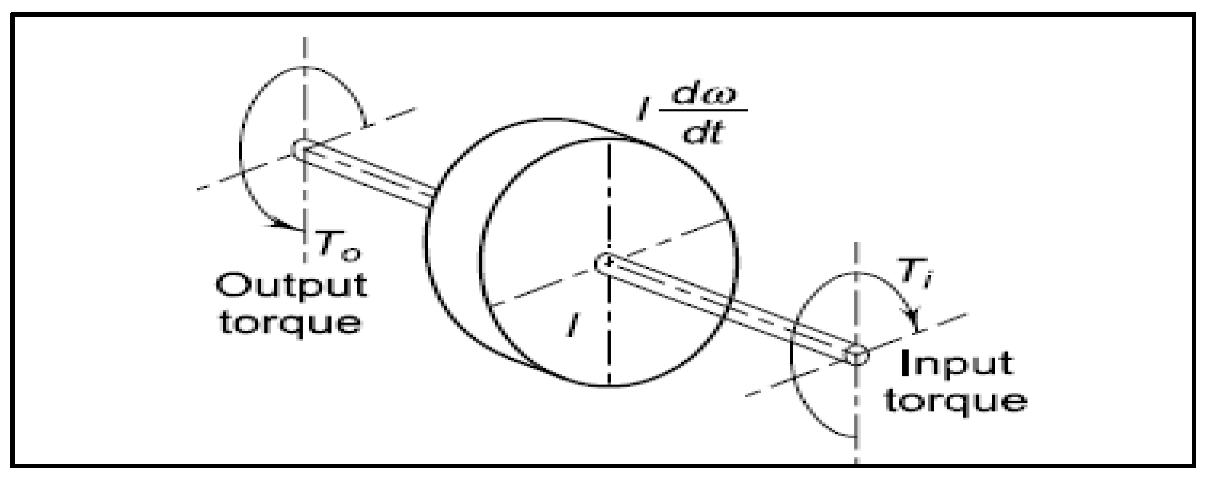
As more inverter-based RES are integrated into the power network, the inertia of the system will remain degraded [35]. A new method has been considered to incorporate a flywheel, similar to that presented in Figure 2. The flywheel keeps kinetic energy and sustains stability in a system. This is achieved by accelerating the rotor and supplying kinetic energy to the power grid. When the protection clears the fault, the flywheel slows down and absorbs energy from the power grid. This exchange of energy between the flywheel-equipped rotor enhances inertia and regulates the RoCoF to maintain stability, and the flywheel dynamically improves the inertia of the system.

Mathematical Modeling of Flywheel Shaft

T o < T i   Output torque is less than input torque; the rotor and flywheel speed up to supply energy to the network.
T i < T o Once input torque is less than output torque, the flywheel slows down, involving the rotor, and captivates the surplus energy from the system; this happens once the protection has removed the fault.

2.3. Data Input Model

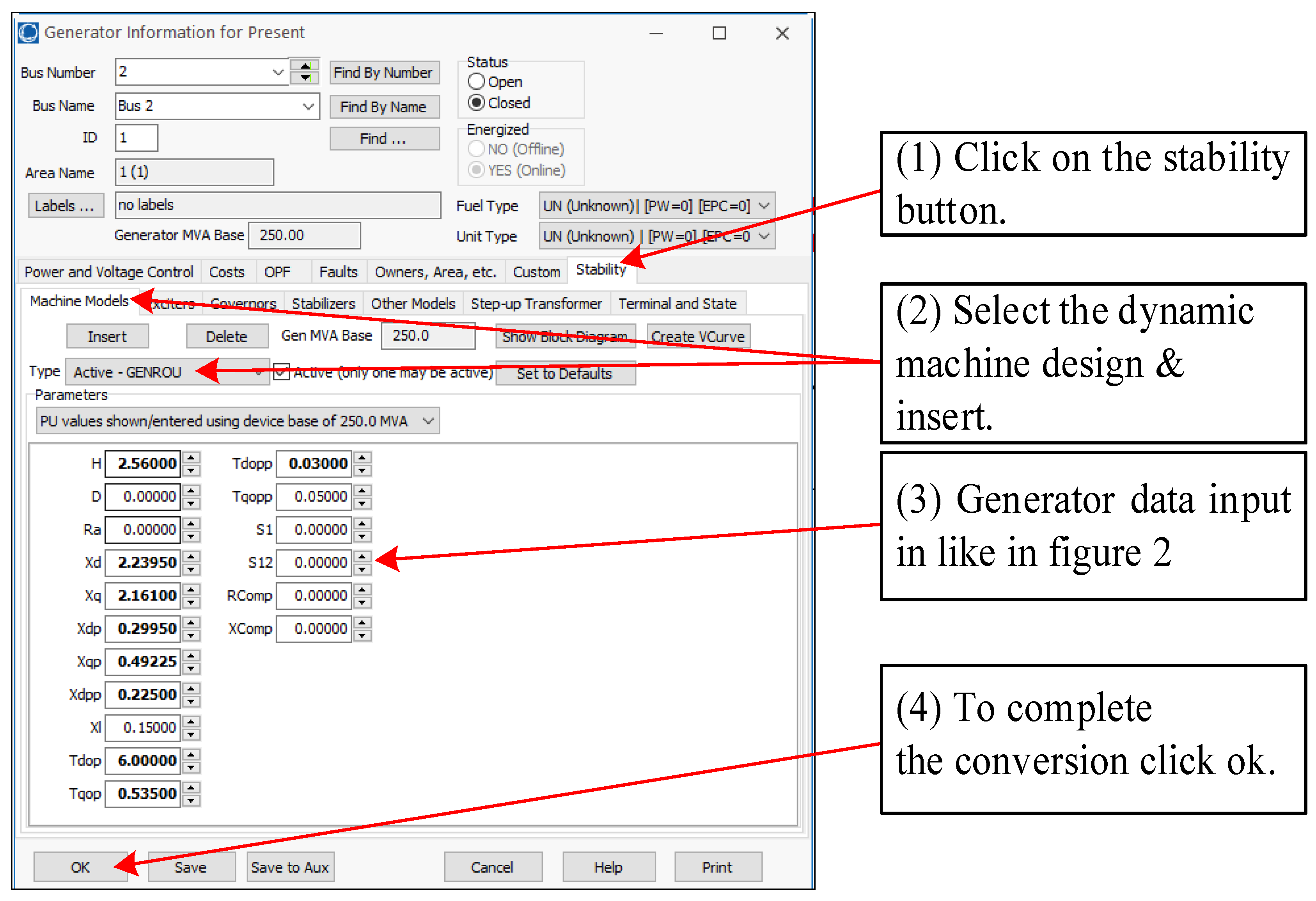
For the system to function in both dynamic and steady condition simulations, a generator, transformer, and line data are necessary. Generator information was created using actual information from an energy plant in Queensland, Australia, and its database and line information is consulted using the overhead Cable Catalog provided by the Olex Cable Manufacturing Company, as listed in Table 3. Figure 3 demonstrates the input statistics and configuration of the generator and line.

2.4. Software Model Configuration and Validation

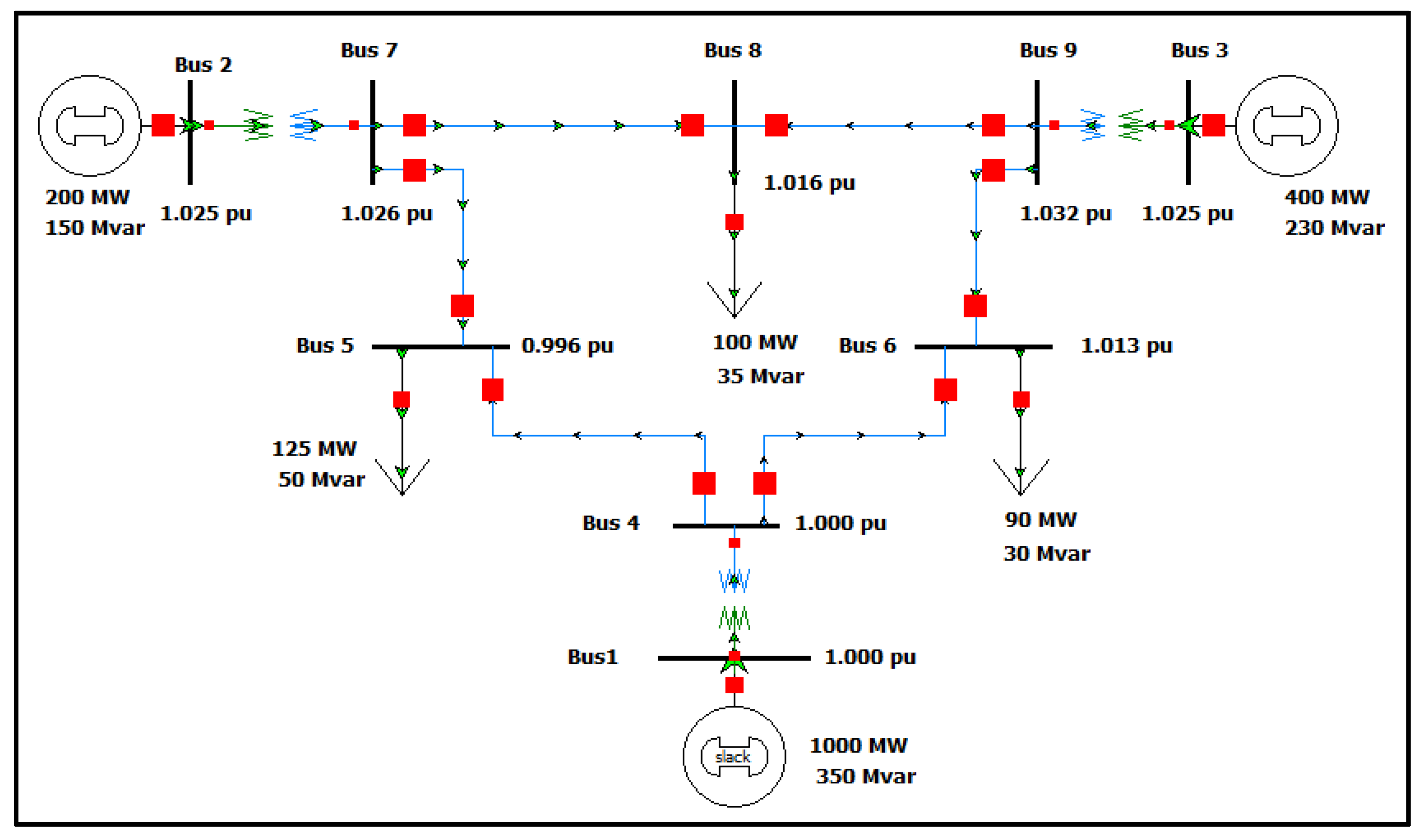
Figure 4 illustrates the 9 bus systems utilized in the investigation for the studies of transient modeling. Generator 1 is represented as an infinite or slack bus to allude to the model on a system voltage of 1.0 pu and a frequency of 50 Hz. The aim of the slack bus is to provide MVAR or MW in the system with a deficiency in generation. A load flow simulation was performed to initialize the model and demonstrate that the model has a solution through convergence (Newton Raphson’s procedure and Euler’s technique). After five iterations, the model converged and was validated; the steady condition values of the power network are displayed as presented in Figure 4. To conduct a simulation of transient stability in the study, a reliable power flow design, as shown in Figure 4, was transformed into a stability design. It was achieved by adding a dynamic generator 2 design and a photovoltaic panel on bus#3. Adding a dynamic design ensures that the generators contribute a fault current and Megavolt amperes during a disturbance. From the load flow studies, the following dynamic models were configured:
(a)
Generator;
(b)
Exciter;
(c)
Governor (not applicable to PV).
Figure 5 displays the procedure used to convert the power flow generator model into a dynamic model. A similar procedure was used to transform exciters, governors, and stabilizers into transient stability models from the load flow.

Newton-Raphson Algorithm

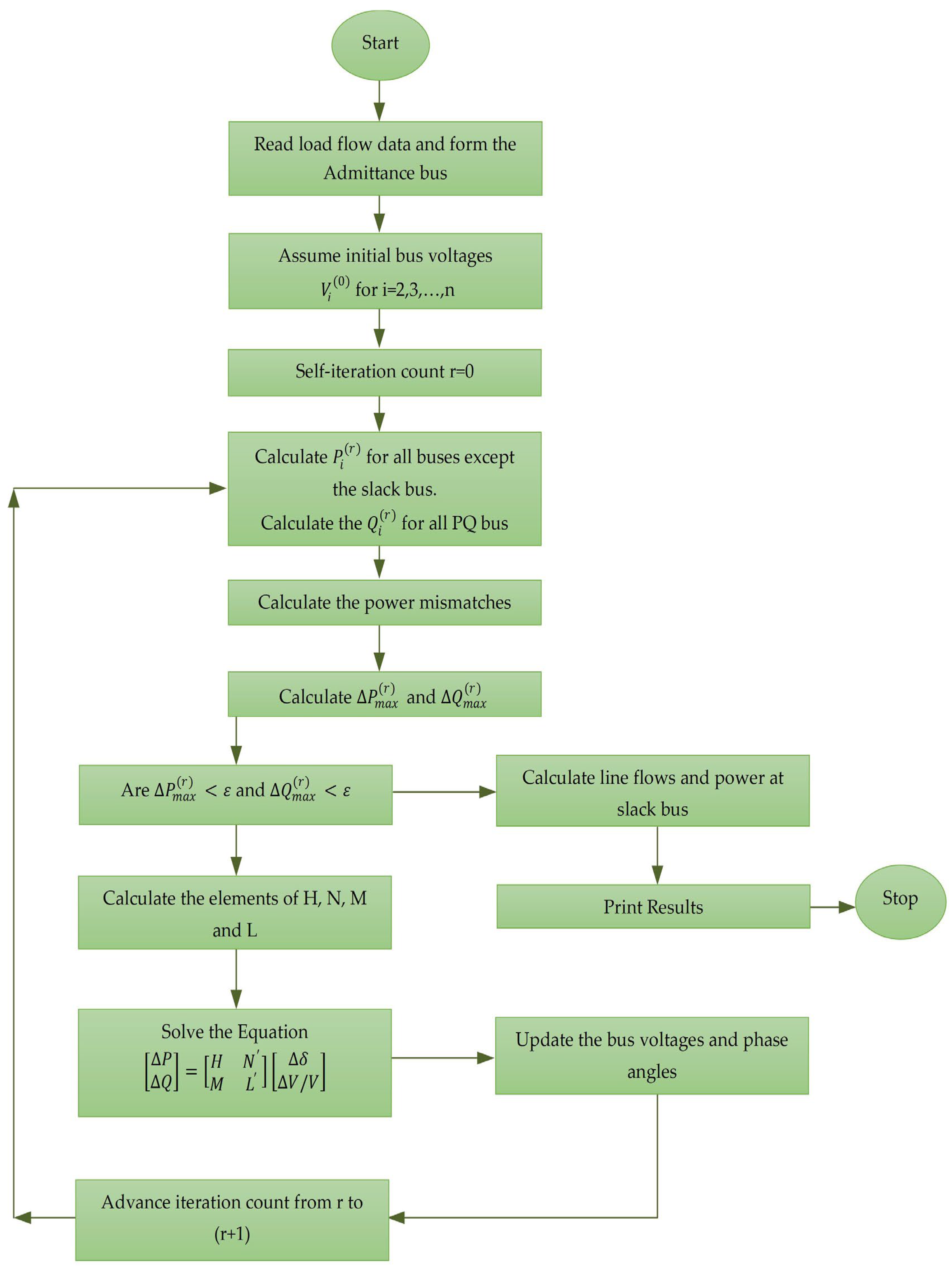
The Newton-Raphson method for charge flow analysis is a powerful method for solving nonlinear algebraic equations. It works faster and reliably converges in most cases compared to the Gauss-Seidel method. It is a practical method for the load flow solution of large power grids. Its only shortcoming is the high memory requirement of the computer, which is overcome with a compact memory scheme. A flowchart is shown in Figure 6 for the Newton-Raphson method utilizing polar coordinates for load flow solutions.

3. Simulation Results and Analysis

The results of the power system modeling discussed in this paper were derived from the PowerWorld simulator. The PowerWorld simulator was selected for the modeling of transient stability as it is a versatile software which can investigate and replicate the original results. It can help in investigations and analysis in a similar way to other accessible software packages at the commercial level, such as PSCAD and PSSE, etc. PowerWorld has the following advantages:
  • The available software for carrying out dynamic model mapping is helpful and can save time when creating a practical model, as well as validation and analysis.
  • The successful creation of expected failure schedules and running them in simulation times.
  • Ease in terms of plotting and graphically displaying the attained results.
Case studies were performed at different levels of PV penetration and PV inverter responses under different grid faults. In this research, symmetrical 3-ϕ faults and L-G faults were performed to investigate the stability of the system at various system contingencies. Although 3-ϕ faults are not usual and have merely positive sequence currents and voltages, they represent the poorest situation of fault levels. A line-to-ground fault represented the poorest situation of unsymmetrical faults, and provided zero, negative, and positive sequence components; the stability of the system was assessed under these scenarios. The incorporation of a flywheel into the synchronous generator dynamically enhanced the inertia of the system.
For the investigation of transient stability, the PowerWorld model in Figure 4 was utilized. The model was explained in detail in Section 2.

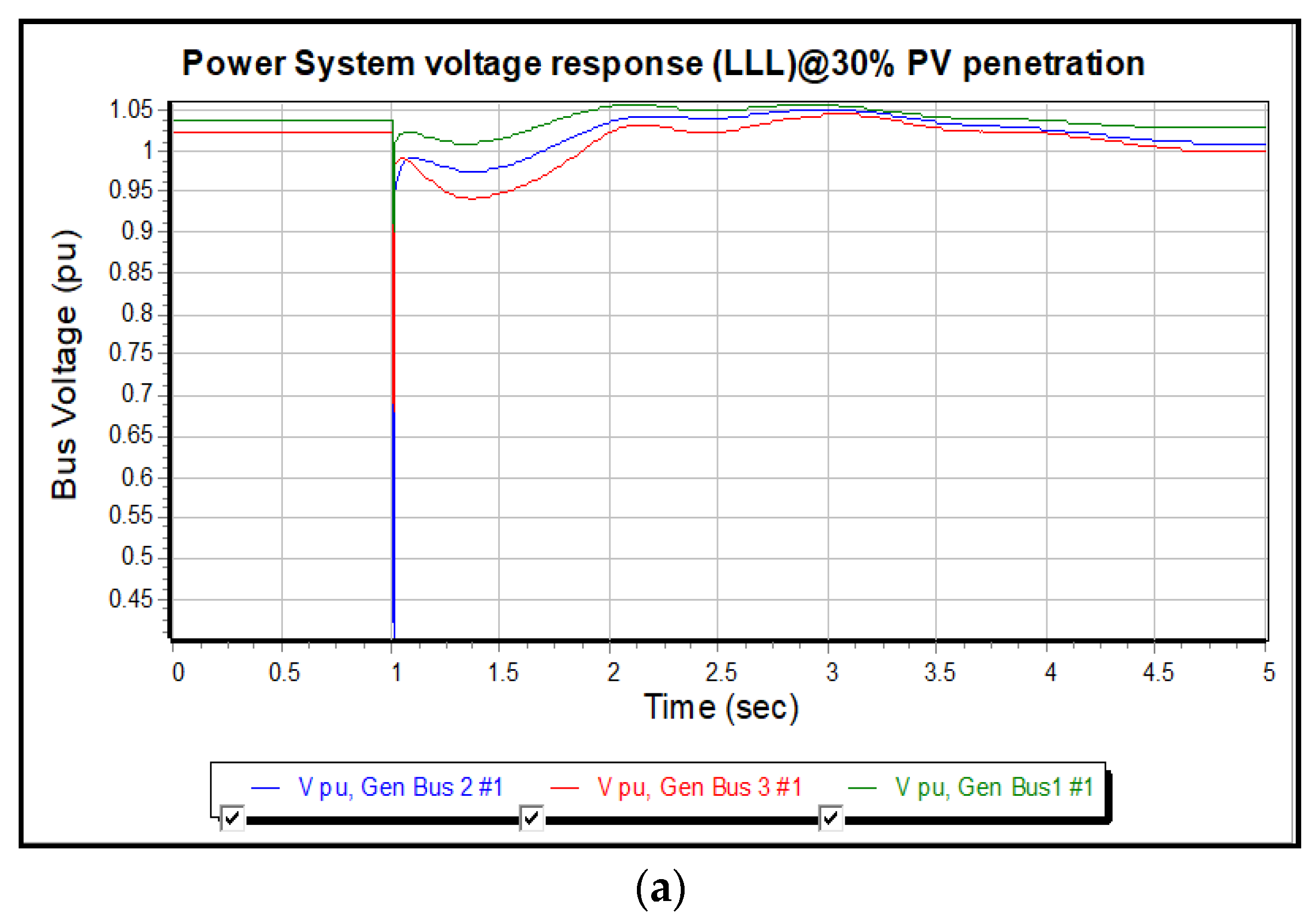
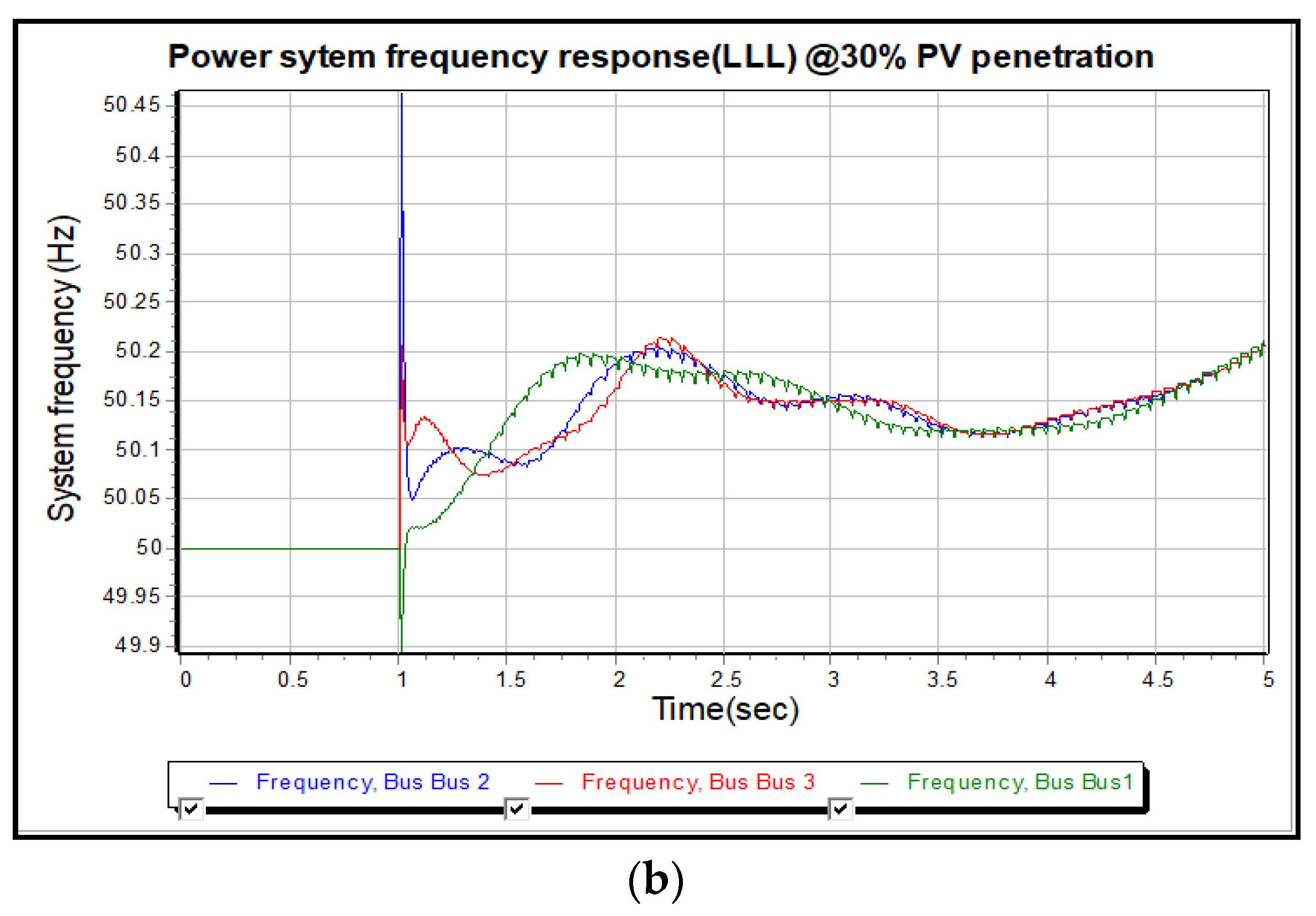
3.1. Case Study 1: 3-ϕ Fault Simulation without Flywheel at 30% PV

The outcomes of Case Study 1 displayed in Figure 7 illustrates the voltage and frequency characteristics when a 3-ϕ fault is performed on the transmission line from bus 5 to bus 7, with a PV active power contribution of 30%. In steady-state situations, the voltage at the synchronous machine bus 1, slack bus 2, and PV bus 3 is between 1 and 1.05 pu, with a network load of 350 MW. After 1 s, a 3-ϕ fault is applied, causing the drop in voltage on all three busses to 0.92 per unit on bus 1; 0.68 per unit on photovoltaic bus#3; and 0.35 per unit on bus#2. The bus#2 experienced the worst voltage dip because of its proximity to the fault. The fault was removed in 0.16 s and voltage recovered to the before-fault stage, as per IEEE:1547. As can be seen in Figure 7a, the voltage of the system recovered to around pre-fault states, excluding slight fluctuations. This situation is supported in the literature review; when the system has enough inertia and strength, the LSPV is capable of RTF. The system frequency before the fault was maintained at 50 Hz. Figure 7b displays the frequency of the system after fault clearance, with the least swing being between 49.9 Hz and 50.45 Hz. The fault was cleared by the X- and Y-line differential and high-speed communication-assisted distance protection, and the frequency of the system settled to 50.2 Hz. The fault clearance period was less than 0.16, according to IEEE 1547 standard. The stability of the frequency illustrates that the system had sufficient inertia to lessen the RoCoF to sustain the stability of the system.

3.2. Case Study 2: 3-ϕ Fault Simulation without Flywheel at 50% PV

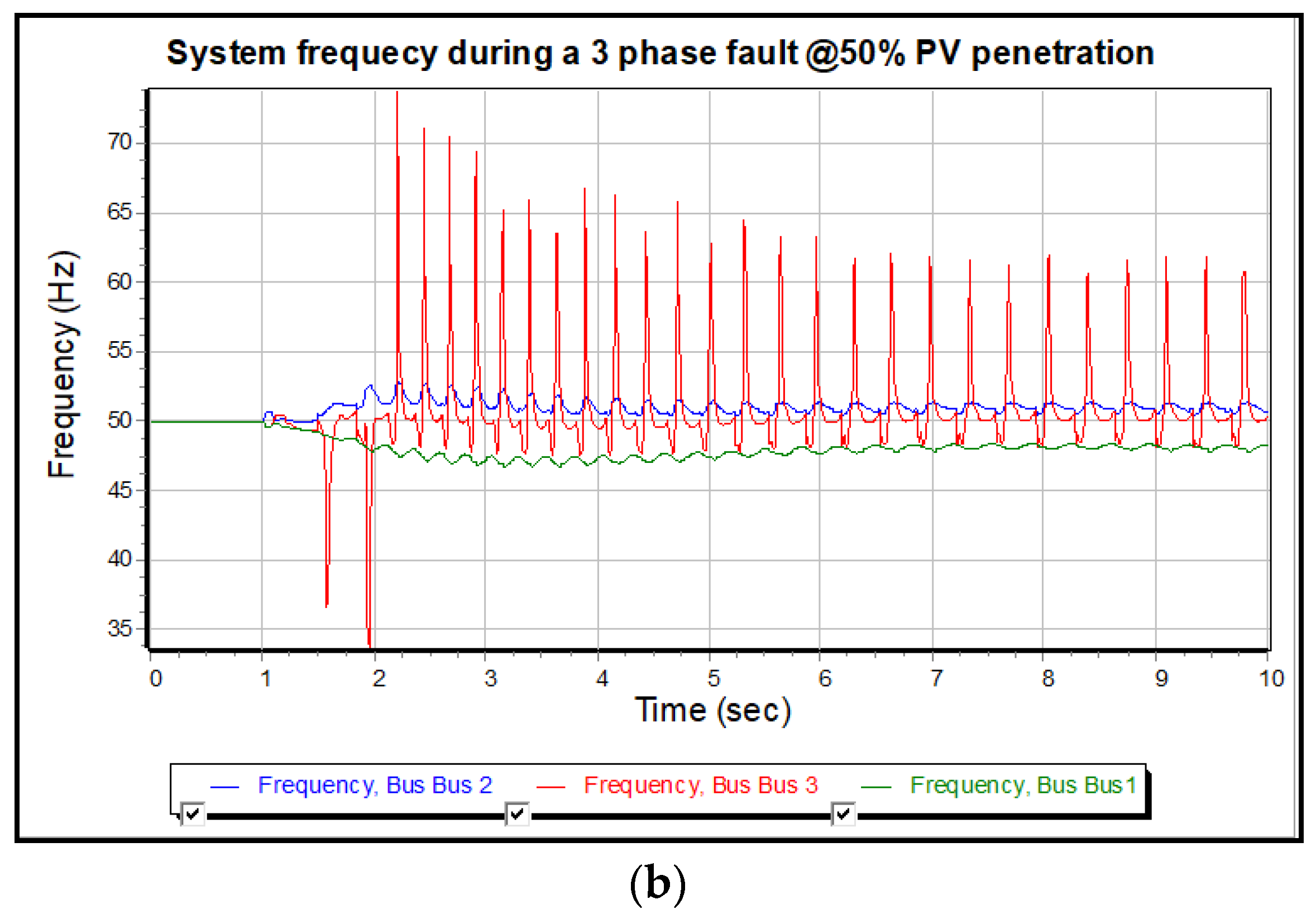
Case Study 2 had a similar setup to Case Study 1, except that the penetration of the photovoltaic was amplified to 50% from 30%. Figure 8 displays the instability of voltage and frequency after clearance of the fault. At 50% penetration, PV had degraded system strength and machines on bus 1 and 2 lost synchronism and disconnected due to low frequency and failed to ride through the low voltage event. Figure 8a,b demonstrates that PV infiltration increased to 50% without inertia and system strength support. The fault was cleared in 1 s. Voltage restoration after the clearance of fault was slow, causing the voltage of the system to collapse after 1.4 s, as illustrated in Figure 8a. The frequency above 70 Hz on PV bus 3 produced a cascading system frequency effect. The unstable frequency of bus 1, which fell to lower than 46 Hz, was unable to return to pre-fault stages.
The PV may work in P mode at the unity Pf and provide the active power or Q mode, providing the reactive power only. However, in this case, it is evident from the results that the PV is not capable of independently controlling active and reactive power, and caused the voltage instability of virtual inertia; therefore, it could not control the fast RoCoF and resulted in frequency instability.

3.3. Case Study 3: 3-ϕ Fault Simulation at 50%-with Flywheel

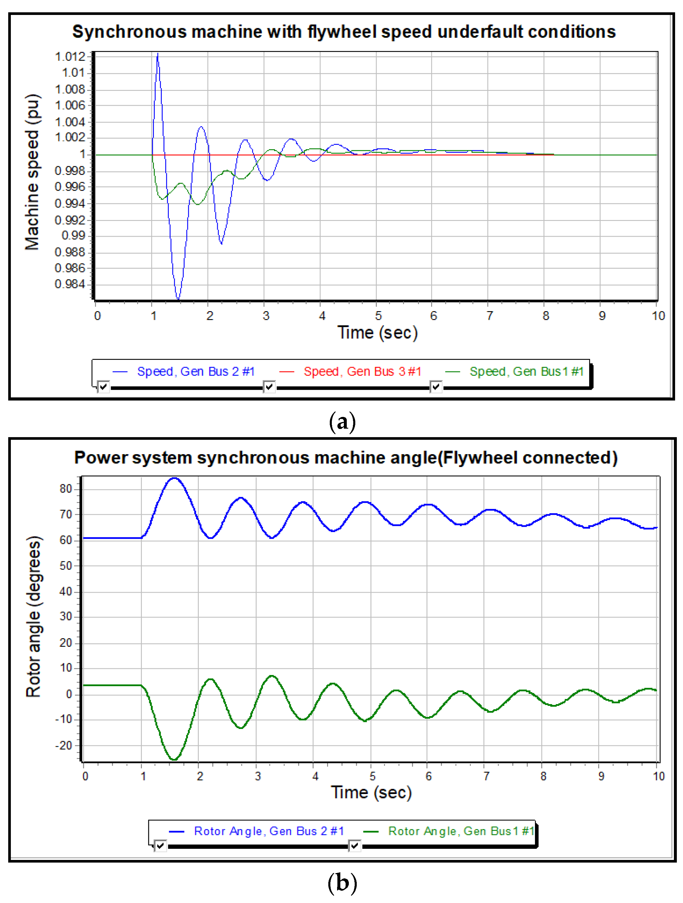
In Case Study 3, a suggested method was analyzed to incorporate a flywheel in a synchronous machine to dynamically enhance the inertia of the system. The results illustrated the reaction of the power system to the stability of the generator speed, rotor angle, voltage, and frequency before and after the 3-ϕ fault simulation. Figure 9a displays the speed response of the generator in steady-state and transient situations. At t = 1 s, a 3-ϕ fault was simulated and the speed of generator increased to 1.012 per unit from 1 pu. The increase in speed was because of the flywheel accelerating the rotor of the machine to supply the kinetic energy into the network. The generator could control the speed between 0.94 and 1.012 pu in a fault, and eventually stabilized at the pre-fault speed with slight fluctuation. This is accredited to the conversation of kinetic energy between the power grid and the rotor-mounted flywheel, which can speed up or slow down the power demands of the rotor. Speed does not apply to PV bus 3, as it used solid state electronics for its control system.
The stability of the generator rotor is a critical parameter in order to make sure that the generators on the grid stay synchronized under all plausible system contingencies. Rotor angle and the speed of the generator are closely related. The change in speed influences the magnitude of the rotor angle. Figure 9b illustrates that the machine on bus 2 sustained stability of the rotor angle between 0–90° in transient and steady-state situations, which is a safety margin for operation under 3-ϕ faults. The infinite/slack bus kept the angle of rotor as near to zero as possible, a good sign of the stability of the rotor angle. Once the fault is removed, the flywheel offers enough inertia to control speed and permits the photovoltaic to run in P mode to aid frequency retrieval.
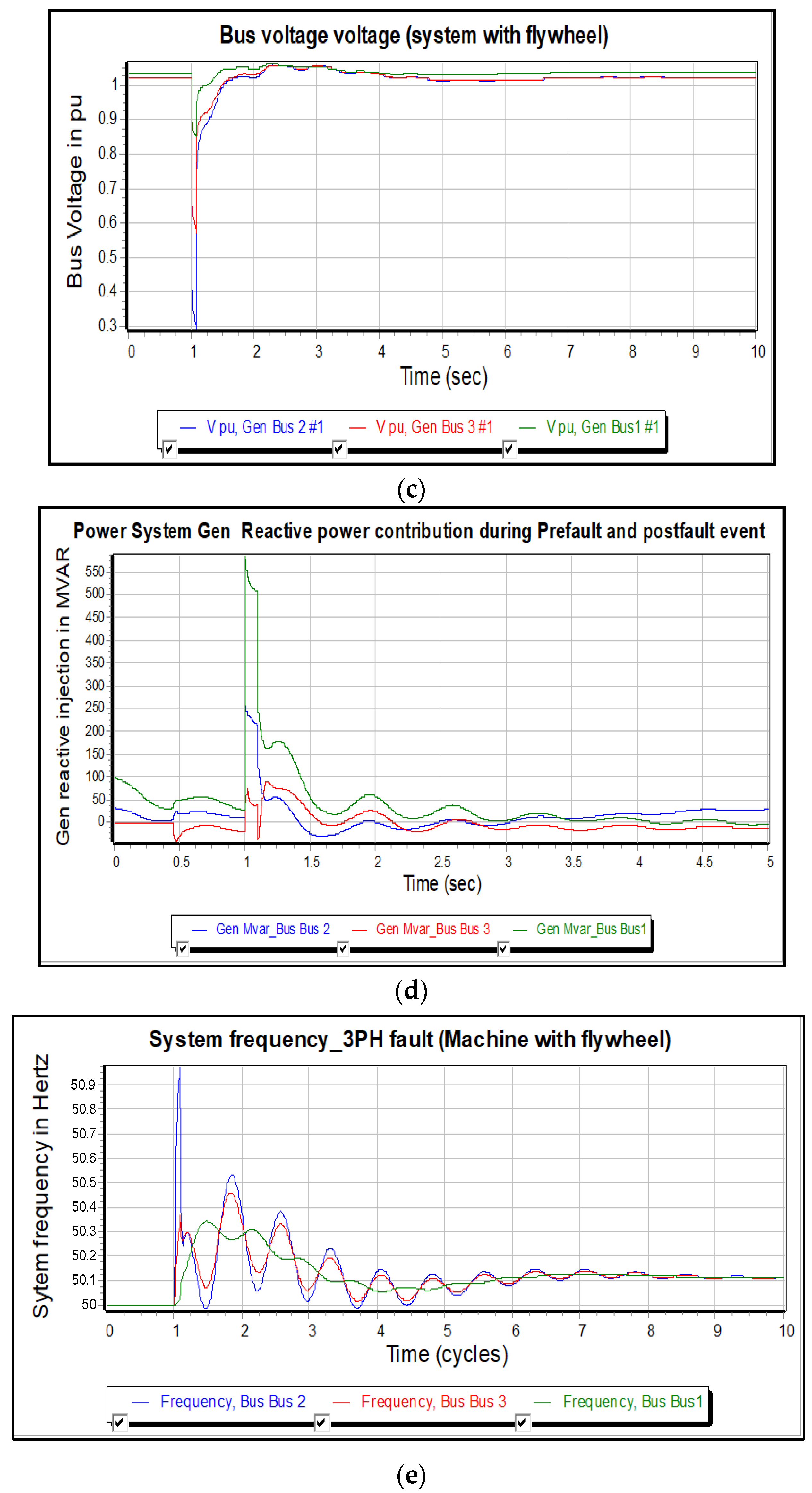
Figure 9c illustrates the steady state voltages of the system and the voltage portfolio of the generator busses during a fault. With a grid load of about 350 MW, the voltage on the three PQ busses is around 1 pu and 1.05 per unit, within constitutional limits in accordance with IEE1547 standard. Voltage regulation is accomplished via inverter volt-var regulation and generator excitation according to the AS/NZS 4771.1. When t = 1 s, at the start of a 3-ϕ fault, the voltage of busses 1, 2, and 3 drop to 0.85, 0.6, and 0.3 per unit, respectively. Once the error is cleared, after 0.1 s, the voltage of the system is retrieved within 1.0 per unit on all busses because of the contribution of the reactive power from the generator sets and flywheel-equipped synchronous machines. Voltage retrieval after a system failure conforms to IEEE 1547 standard.
Figure 9d illustrates the way in which the system provides voltage support during a system fault. The PV before the fault on bus 3 draws reactive power to reduce the steady-state voltage; Generator 1 and 2 supply the reactive power requirements of the grid before the fault. During a disturbance at time t = 1 s, the three machines on busses 1, 2, and 3 contributed reactive power to increase the voltages of the system.
The slack bus supplies 500 Mvar; the flywheel-equipped synchronous machine on the bus supplies 250 Mvar; and the LSPV on bus 3 supplies 60 Mvar. The results reveal the limits of PV var control and the superiority of a synchronous machine equipped with a flywheel that may provide both inertia and voltage support.
Figure 9e demonstrates the stability of the frequency during a 3-ϕ fault in the system. The flywheel comprises the machine rotor providing enough inertia to regulate the rapid RoCoF. The accurate frequency control is because of the speed control of the generator in Figure 9a, and the stability of rotor angle in Figure 9b. At 1 s, a 3-ϕ fault resulted in 125 MW load rejection and an over-frequency event. At the time of the fault, the frequency fluctuated between 50.9 and 59.1, eventually stabilizing at the pre-fault setting after the fault was cleared.

3.4. Case Study 4: Asymmetrical Fault L-G Fault with Consideration of 50% PV

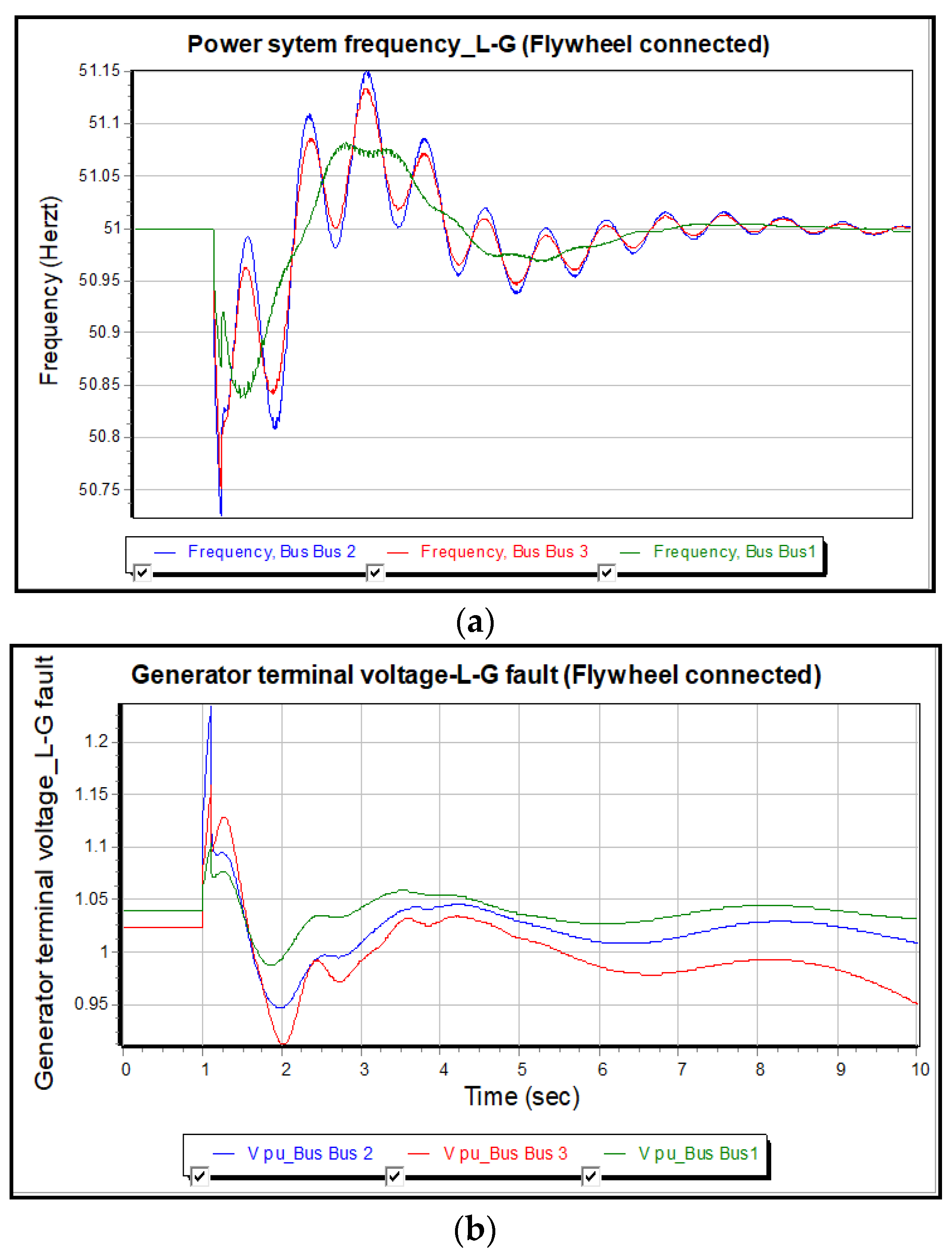
L-G faults are normal in the grid and represent the poorest unbalanced faults; they contain negative, positive, and zero-sequence constituents. A case scenario was carried out to illustrate the FRT ability of the system with a synchronous machine equipped by a flywheel. Line-to-ground caused a frequency drop (51 Hz frequency reference software scaling problem). Figure 10a demonstrates that the system frequency changed after the line-to-ground fault. The frequency fluctuated between 49 and 51.15 Hz. Once the fault was isolated, the frequency stabilized at the pre-fault setting. The system successfully stabilized the frequency during the line-to-ground fault. Figure 10b demonstrates that the system rode through high and low voltages during the line-to-ground fault. The abnormally high voltage of 1.23 p.u was because of the large impedance earthing on the generator transformer on busses 1, 2, and 3, and caused an overvoltage on two healthy phases during the L-G fault. The voltage across the generator slightly increased and stabilized once the fault was isolated.
Table 4 shows a summary of the simulation outcomes of the four case studies. Based on the simulation results, the synchronous machine with a rotor flywheel design dynamically improved the inertia of the system and enhanced PV fault recovery capability. Case Study 2 showed that, at 50% PV infiltration with no system inertia, the inertia and strength of the support system decreased. Case Studies 3 and 4, carried out using synchronous machines equipped with a flywheel, illustrated the constancy of the system for balanced and unbalanced faults.

4. Conclusions

Analysis of dynamic designs for inverters used on large-scale has been broadly studied in both the industrial and educational sectors. Literature analysis shows that the virtual inertia of photovoltaic inverters may bring stability to the system. It must be realized that virtual inertia may not be relied upon to provide network support in a large system led via inverter-based renewable resources. Virtual inertia does not have the ability to regulate the RoCoF and may cause an instability of frequency. Case Study 2 results showed that the inertia and strength of the system significantly decreased at 50% PV penetration. Modeling demonstrated that PV inverters either work in the P mode, in which they function at unity power factor (PF) and merely produce real power, or in a Q mode, where it supplies only reactive power, unlike a synchronous machine which simultaneously provides reactive and real power, and provides inertia and system support under disturbance. To enhance the stability of a system in a grid dominated by PV, inertia alleviation approaches using flywheel technology may be a choice. PowerWorld modeling, creating a power system with a synchronous machine fitted with a flywheell improves system stability by:
  • Enhanced LVRT for power grids with high photovoltaic penetration.
  • Provides quick, dynamic reactive support to aid voltage retrieval.
  • Provides stability of frequency by regulating the rapid RoCoF during a disturbance.
Therefore, it is credible to conclude that the proposed modification of the synchronous machine rotor coupled with a flywheel will dynamically improve system inertia and strength, and help improve system stability in large power networks dominated by renewable energy of varying sizes. This study was based on conventional PV systems, but research is always progressing in this field. Hence, in future work, modern concepts such as droop-control-based PV inverters can be used for both real and reactive power supply depending on the grid voltage and frequency deviation. Furthermore, one proposal is to conduct field tests by designing hardware, which includes a synchronous machine and flywheel for the purpose of validating the simulation results.

Author Contributions

The author contributions are as follows: Conceptualization, M.M. and M.B.; methodology, M.B. software, M.M.; validation, M.B. and M.A.; formal analysis, M.B.; investigation, M.M. and M.A.; resources, M.M. and N.Z.; data curation, M.M.; writing—original draft preparation, M.M. and N.Z. writing—review and editing, N.Z. and M.M.; visualization, M.B.; supervision, M.B. project administration, M.A.; funding acquisition, M.B. All authors have read and agreed to the published version of the manuscript.

Funding

This research received no external funding.

Data Availability Statement

The information used to support the verdicts of this study are available from the corresponding author upon request.

Conflicts of Interest

The authors declare that they have no conflict of interest.

Nomenclature

BESSBattery Energy Storage Systems
Hz Hertz (cycles per seconds)
IBRInverter-based energy resources
L-GLine to Ground
LSPV Large Scale Photovoltaic
LVRTLower Voltage Ride Through
MVARMega volt amps reactive
MWMegawatts
pu Per unit
PVPhotovoltaic
RoCOFRate of Change of system frequency
sec Seconds
STATCOMsStatic Compensators
SVCsStatic Var Compensators

References

  1. Streck, C. The Paris Agreement. Summary. Brief. Note III. No. December 2015, p. 1. Available online: http://unfccc.int/resource/docs/2015/cop21/eng/l09r01.pdf (accessed on 28 December 2015).
  2. Lei, T.; Riaz, S.; Zanib, N.; Batool, M.; Pan, F.; Zhang, S. Performance Analysis of Grid-Connected Distributed Generation System Integrating a Hybrid Wind-PV Farm Using UPQC. Complexity 2022, 2022, 1–14. [Google Scholar] [CrossRef]
  3. Malinowski, M.; Leon, J.I.; Abu-Rub, H. Solar Photovoltaic and Thermal Energy Systems: Current Technology and Future Trends. Proc. IEEE 2017, 105, 2132–2146. [Google Scholar] [CrossRef]
  4. Sector by Sector: Where Do Global Greenhouse Gas Emissions Come from?—Our World in Data. Available online: https://ourworldindata.org/ghg-emissions-by-sector (accessed on 27 April 2022).
  5. Zanib, N.; Batool, M.; Riaz, S.; Afzal, F.; Munawar, S.; Daqqa, I.; Saleem, N. Analysis and Power Quality Improvement in Hybrid Distributed Generation System with Utilization of Unified Power Quality Conditioner. Comput. Model. Eng. Sci. 2022, 134, 1105–1136. [Google Scholar] [CrossRef]
  6. Zanib, N.; Batool, M.; Riaz, S.; Nawaz, F. Performance Analysis of Renewable Energy Based Distributed Generation System Using ANN Tuned UPQC. IEEE Access 2022, 10, 110034–110049. [Google Scholar] [CrossRef]
  7. Li, L.; Li, H.; Tseng, M.L.; Feng, H.; Chiu, A.S.F. Renewable energy system on frequency stability control strategy using virtual synchronous generator. Symmetry 2020, 12, 1697. [Google Scholar] [CrossRef]
  8. Abdollahi, M.; Candela, J.I.; Tarraso, A.; Elsaharty, M.A.; Rakhshani, E. Electromechanical design of synchronous power controller in grid integration of renewable power converters to support dynamic stability. Energies 2021, 14, 8. [Google Scholar] [CrossRef]
  9. Gu, H.; Yan, R.; Saha, T.K. Minimum Synchronous Inertia Requirement of Renewable Power Systems. IEEE Trans. Power Syst. 2018, 33, 1533–1543. [Google Scholar] [CrossRef] [Green Version]
  10. 8th on Power Systems Theme: Transition towards Sustainable… & Middot; PDF File Papers Must Conform to IEEE Format and Specifications. All Papers Must Be Original and Not Simultaneously—[PDF Document]. Available online: https://fdocuments.net/document/8th-on-power-systems-theme-transition-towards-sustainable-papers-must-conform.html (accessed on 27 April 2022).
  11. Khatib, H. Electricity trading. In Economic Evaluation of Projects in the Electricity Supply Industry; IET: London, UK, 2014; pp. 197–211. [Google Scholar] [CrossRef]
  12. Orihara, D.; Kikusato, H.; Hashimoto, J.; Otani, K.; Takamatsu, T.; Oozeki, T.; Taoka, H.; Matsuura, T.; Miyazaki, S.; Hamada, H.; et al. Contribution of voltage support function to virtual inertia control performance of inverter-based resource in frequency stability. Energies 2021, 14, 4220. [Google Scholar] [CrossRef]
  13. Clean Energy Australia Report 2022. Available online: https://apo.org.au/node/317318 (accessed on 27 April 2022).
  14. Wu, Y.; Wu, Y.; Cimen, H.; Vasquez, J.C.; Guerrero, J.M. P2P energy trading: Blockchain-enabled P2P energy society with multi-scale flexibility services. Energy Rep. 2022, 8, 3614–3628. [Google Scholar] [CrossRef]
  15. IRENA. Global Renewables Outlook: Energy Transformation 2050; International Renewable Energy Agency: Abu Dhabi, United Arab Emirates, 2020. [Google Scholar]
  16. Patil, A.; Girgaonkar, R.; Musunuri, S.K. Impacts of increasing photovoltaic penetration on distribution grid—Voltage rise case study. In Proceedings of the 2014 International Conference on Advances in Green Energy (ICAGE), Thiruvananthapuram, India, 17–18 December 2014; pp. 100–105. [Google Scholar] [CrossRef]
  17. Lazzeroni, P.; Olivero, S.; Stirano, F.; Repetto, M. Impact of PV penetration in a distribution grid: A Middle-East study case. In Proceedings of the 2015 IEEE 1st International Forum on Research and Technologies for Society and Industry Leveraging a better tomorrow (RTSI), Turin, Italy, 16–18 September 2015; pp. 353–358. [Google Scholar] [CrossRef]
  18. Venikov, V.A. Transient Phenomena in Electrical Power Systems; Elsevier: Amsterdam, The Netherlands, 1965. [Google Scholar] [CrossRef]
  19. Australian Energy Market Operator (AEMO). Systsem Strength, Important Notice; Australian Energy Market Operator (AEMO): Melbourne, Australia, 2020; Volume 35. [Google Scholar]
  20. Song, P.; Shi, Z.; Wu, Q.; Yang, Y.; Zhang, L.; Wu, B.; Song, M.; Qu, T. General design of a 300-kvar hts synchronous condenser prototype. IEEE Trans. Appl. Supercond. 2020, 30, 5206905. [Google Scholar] [CrossRef]
  21. Kalsi, S.S.; Madura, D.; Ingram, M. Superconductor synchronous condenser for reactive power support in an electric grid. IEEE Trans. Appl. Supercond. 2005, 15, 2146–2150. [Google Scholar] [CrossRef]
  22. Yan, G.; Wang, D.; Jia, Q.; Hu, W.; Zhou, G. A novel frequency regulation control strategy based on the external characteristics of PV generation. IET Conf. Publ. 2019, 2019, 185–186. [Google Scholar] [CrossRef]
  23. Selwa, F.; Djamel, L.; Imen, L.; Hassiba, S. Impact of PSS and STATCOM on transient stability of multi-machine power system connected to PV generation. In Proceedings of the 2015 International Conference on Renewable Energy Research and Applications (ICRERA), Palermo, Italy, 22–25 November 2015; pp. 1416–1421. [Google Scholar] [CrossRef]
  24. Mitsugi, Y.; Yokoyama, A. Phase angle and voltage stability assessment in multi-machine power system with massive integration of PV considering PV’s FRT requirements and dynamic load characteristics. In Proceedings of the 2014 International Conference on Power System Technology, Chengdu, China, 20–22 October 2014; pp. 1112–1119. [Google Scholar] [CrossRef]
  25. He, Y.; Wang, M.; Jia, Y.; Zhao, J.; Xu, Z. Low-voltage ride-through control for photovoltaic generation in the low-voltage distribution network. IET Renew. Power Gener. 2020, 14, 2727–2737. [Google Scholar] [CrossRef]
  26. Lammert, G.; Heß, T.; Schmidt, M.; Schegner, P.; Braun, M. Dynamic grid support in low voltage grids—Fault ride-through and reactive power/voltage support during grid disturbances. In Proceedings of the 2014 Power Systems Computation Conference, Wroclaw, Poland, 18–22 August 2014. [Google Scholar] [CrossRef]
  27. Refaat, S.S.; Abu-Rub, H.; Sanfilippo, A.P. Dynamic voltage stability impact of large-scale photovoltaic system on electric power grids. In Proceedings of the 5th IET International Conference on Renewable Power Generation (RPG) 2016, London, UK, 21–23 September 2016. [Google Scholar] [CrossRef]
  28. Hoballah, A. Power system dynamic behavior with large scale solar energy integration. In Proceedings of the 2015 4th International Conference on Electric Power and Energy Conversion Systems (EPECS), Sharjah, United Arab Emirates, 24–26 November 2015. [Google Scholar] [CrossRef]
  29. Hasan, A.K.M.K.; Haque, M.H.; Aziz, S.M. Application of battery energy storage systems to enhance power system inertia. In Proceedings of the 2019 29th Australasian Universities Power Engineering Conference (AUPEC), Nadi, Fiji, 26–29 November 2019. [Google Scholar] [CrossRef]
  30. Silwal, S.; Karimi-Ghartemani, M. On Transient Responses of a Class of PV Inverters. IEEE Trans. Sustain. Energy 2019, 10, 311–314. [Google Scholar] [CrossRef]
  31. Uxvkhg, R.I.R.; Iru, O. Synchronverter-based operation of STATCOM to mimic Synchronous Condensers. In Proceedings of the 2012 7th IEEE Conference on Industrial Electronics and Applications (ICIEA), Singapore, 18–20 July 2012. [Google Scholar]
  32. Mrehel, O.G.; Shamek, A.S.; Hamouda, M.D. Power system transient stability investigation in the presence of photovoltaic generation. In Proceedings of the 2016 17th International Conference on Sciences and Techniques of Automatic Control and Computer Engineering (STA), Sousse, Tunisia, 19–21 December 2016. [Google Scholar] [CrossRef]
  33. Teodorescu, R.; Liserre, M.; Rodriguez, P. Grid Converters for Photovoltaic and Wind Power Systems Chapter 10 Control of Grid Converters under Grid Faults; John Wiley & Sons: Hoboken, NJ, USA, 2011. [Google Scholar]
  34. IEEE Std 1547; IEEE Standard for Interconnection and Interoperability of Distributed Energy Resources with Associated Electric Power Systems Interfaces. IEEE: Piscataway, NJ, USA, 2018.
  35. Australian Energy Market Operator (AEMO). Power Systsem Requirements, Important Notice; Australian Energy Market Operator (AEMO): Melbourne, Australia, 2020. [Google Scholar]
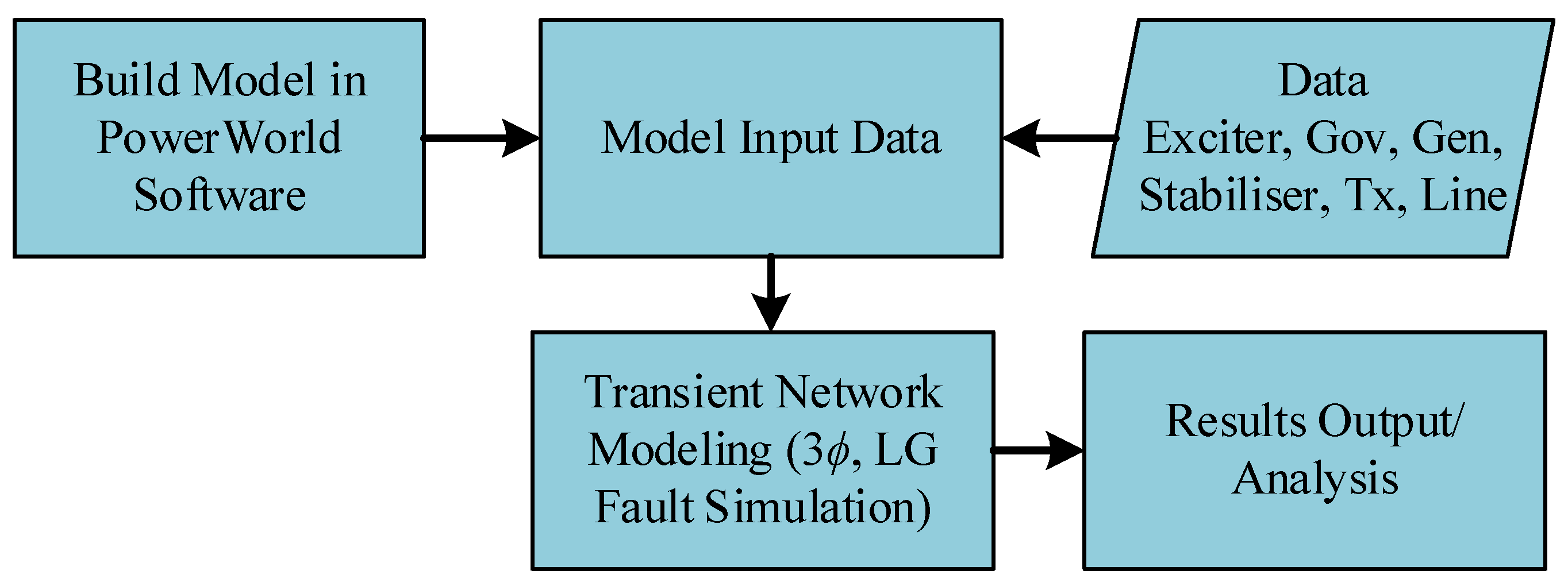
Figure 1. Methodology flow chart.
Energies 16 00689 g001
Figure 2. Rotor of synchronous machine.
Energies 16 00689 g002
Figure 3. Line and generator data: (a) exciter input statistics and configuration; (b) machine stabilizer input statistics and configuration.
Energies 16 00689 g003
Figure 4. Power world network load flow model validation.
Energies 16 00689 g004
Figure 5. Alteration of the model of load flow to transient constancy design.
Energies 16 00689 g005
Figure 6. Flow chart of the Newton-Raphson method.
Energies 16 00689 g006
Figure 7. 3-ϕ fault simulation without flywheel at 30% PV Penetration: (a) power system voltage response; (b) power system frequency response.
Energies 16 00689 g007aEnergies 16 00689 g007b
Figure 8. 3-ϕ fault simulation without flywheel at 50% PV Penetration: (a) voltage response; (b) system frequency response.
Energies 16 00689 g008aEnergies 16 00689 g008b
Figure 9. 3-ϕ fault simulation at 50% PV Penetration with flywheel: (a) generator rotor speed; (b) generator rotor angle stability graph; (c) system voltage recovery after a 3-ϕ fault; (d) reactive power contribution from considered power system; (e) response of considered system frequency after occurrence of 3-ϕ fault.
Energies 16 00689 g009aEnergies 16 00689 g009b
Figure 10. Simulation of asymmetrical fault (L-G fault at 50% PV Penetration): (a) response power system frequency; (b) voltage recovery of power system after line-to-ground fault.
Energies 16 00689 g010
Table 1. Main features comparison for existing techniques available in the literature and this paper.
Ref.TechniquesParameters to be ControlledComments
InertiaIncrease Inertia RangeSystem StrengthVoltageFrequency
[17]Synchronous CondenserYesFixedYesYesYesExtensive, narrow, control range-Rotor Only
[19]SVCNoNoNoYesNo
[19]STATCOMNoNoNoYesNo
[25]BatteriesNoNoYesYesLimited Capability
[26]InvertersVirtual InertiaNoYes (Limited)YesNo
This PaperSynchronous Machine With FlywheelYesYes-Wide RangeYesYesYesCheap Use existing infrastructure dynamic range: Rotor + Flywheel
Table 2. Disconnection time for voltage and frequency violation.
IEEE 1547
Range of Voltage (%)Disconnection Time (s)Range of Frequency (Hz)Disconnection Time (s)
V < 500.1659.3 < V < 60.50.16
50 ≤ V < 882.00
110 < V < 1201.00
V ≥ 1200.16
Table 3. Parameter of Generator Impedance and Time Contact.
Generator 1 and 2 Parameters
Ra (pu)2.7153 × 10 2 Xd ″ (pu)0.250
X1 (pu)0.171Xq ″ (pu)0.240
Xd (pu)1.204Td1.01
Xq (pu)0.437Td ″ (s)0.052
Xd ′ (pu)0.294Tq ″ (s)0.13
Table 4. Summary of Simulation Results.
ParametersBus#1 (Slack/Infinite)Bus#2Bus#3 (Photovoltaic)
Initialisation of Model
Load Flow (Steady State Value)
Voltage (p.u)11.051.05
Frequency (Hz)505050
Voltage angle (degree)00.60.85
Case Study 1 and 2Values of before-fault with no flywheel
Voltage p.u (case#1)
Voltage p.u (case#2)
1.04
1.03
1.02
1.03
1.02
1.02
Frequency Hz (case#1)
Frequency Hz (case#2)
50
50
50
50
50
50
Case Study 1 and 2Worst situation values in disturbance with no flywheel
Voltage p.u (case#1)
Voltage p.u (case#2)
0.91
0.85
0.2
0.32
0.65
0.25
Frequency Hz (case#1)
Frequency Hz (case#2)
49.9
47
50.45
53
50.15
70
Case Study 1 and 2Values of after-fault with no flywheel
Voltage p.u (case#2)1.031.020.98
Frequency Hz (case#2)50.150.150.1
Case Study 3Parameter values for before fault condition using flywheel
Rotor Speed (p.u)11Not valid for PV
Angle of rotor (degree)3.062.1Not valid
Voltage attained (p.u)1.021.031.02
Frequency (Hz)505050
Reactive power (MVAR)100.048.00
Case Study 3Parameter values in worst condition with disturbance using flywheel
Speed of rotor (p.u)0.991.012Not valid for PV
Angle of rotor (degree)1585Not valid for PV
Voltage (p.u)0.890.30.59
Frequency (Hz)50.350.950.35
Reactive power (MVAR)56025055
Case Study 3Values of after-fault using a flywheel
Speed of rotor (p.u)11.01Not valid
Angle of rotor (degree)163.1Not valid
Voltage (p.u)11.031.01
Frequency (Hz)50.150.150.1
Reactive power (MVAR)20450
Case study 4Values of before-Fault using Flywheel
Voltage (p.u)1.041.041.03
Frequency (Hz)505050
Case study 4Worst Condition Values in Disturbance Using a Flywheel
Voltage (p.u)1.11.231.15
Frequency (Hz)49.854949.25
Case study 4Values of after Fault using a Flywheel
Frequency (Hz)50.0450.0450.4
Voltage (p.u)1.041.020.95
Disclaimer/Publisher’s Note: The statements, opinions and data contained in all publications are solely those of the individual author(s) and contributor(s) and not of MDPI and/or the editor(s). MDPI and/or the editor(s) disclaim responsibility for any injury to people or property resulting from any ideas, methods, instructions or products referred to in the content.