Article

A Disturbed Voussoir Beam Structure Mechanical Model and Its Application in Feasibility Determination of Upward Mining

1
College of Mining Engineering, Taiyuan University of Technology, Taiyuan 030024, China
2
Shanxi Province Coal-Based Resources Green and High-Efficiency Development Engineering Center, Taiyuan 030024, China
3
Postdoctoral Centre, Shandong Energy Group Co., Ltd., Jinan 250014, China
4
Yangcheng County Yangtai Group Industrial Co., Ltd., Jincheng 048100, China
*
Authors to whom correspondence should be addressed.
Energies 2023, 16(20), 7190; https://doi.org/10.3390/en16207190
Submission received: 6 October 2023 / Revised: 11 October 2023 / Accepted: 19 October 2023 / Published: 21 October 2023
(This article belongs to the Special Issue Optimization of Coal Mining and Fossil Energy)

Abstract

:
China is endowed with a large quantity of residual coal resources that require upward mining. The stability of interburden strata structures and accurate determination are crucial for safe mining. Therefore, we established a mechanical model of disturbed voussoir beam structures of interburden strata in upward mining. The model was solved, and stability analysis and instability mechanism analysis were conducted. Based on this model, a new method for determining the feasibility of upward mining was proposed and applied to the upward mining of coal seam No. 7 in Baijiazhuang Coal Mine. A physical simulation experiment and numerical simulation were conducted to validate the method. Through research, it was found that the model had two instability mechanisms: rotation instability and sliding instability. When the disturbance load crossed the critical block of the structures, the model was most likely to experience sliding instability. When the disturbance load acted entirely on the critical block, rotation instability was more likely to occur. The result of the determination, performed using the new method, showed that there was no rotation instability or sliding instability in the interburden strata structures of coal seam No. 7, indicating that the coal seam could be mined upward. This result was consistent with the determinations using the statistical method, “three-zone” method, and balanced surrounding rock method. Physical and numerical simulations revealed that the upward mining of coal seam No. 7 caused the subsidence, rotation, and separation compaction of the interburden strata structures but that the structures remained stable. The results indicate that the proposed model and method have accuracy and applicability, being able to guide the practical feasibility determination of upward mining.

1. Introduction

Due to historical and technological limitations, China’s residual coal reserves are estimated to be around 40 billion tons, of which 34% to 45% needs to be mined through upward mining [1]. Feasibility determination is the core prerequisite for upward mining [2,3]. The current methods used to determine the feasibility of upward mining have developed from empirical determination into quantitative determination. Traditional methods of upward mining determination, both domestically and internationally, include the ratio value method, statistical method, and determination method based on “three zones” of overburden rock [4,5,6]. There are two discriminant standards of the ratio value method, namely, the mining influence factor and OB/IB [7]. The former refers to the ratio of coal seam spacing (H) to the mining height (M) of the lower coal seam, while the latter refers to the ratio of overburden thickness to interburden strata thickness. This method is widely applied, both domestically and internationally. However, the critical range of the mining influence factor is from 6 to 20, and the two critical values for OB/IB are 7 and 16, with a wide range of variation for the critical values. Both the statistical method and “three-zone” method are also related to M and H [8,9,10,11], and they, respectively, assert that when H satisfies Equations (1) and (2), upward mining can be carried out:
H > 1.14 M 2 + 4.14
H > 100 M C 1 M + C 2
In Equation (2), factors C1 and C2 reflect the lithology of the overburden rock, and their values differ in the three types of overburden rock—“soft”, “medium–hard”, and “hard”. When the rock goes from soft to hard, the values of C1 are 6.2, 4.7, and 2.1, respectively, and the values of C2 are 32, 19, and 16, respectively [9]. Scholars from the former Soviet Union and Poland have also derived feasibility determination equations for upward mining that take into account factors such as the bulking coefficient and the thickness of the lower coal seam. The ratio value method, statistical method, and “three-zone” method are used to guide upward mining operations, but they mainly consider the relationship between coal seam spacing and lower coal seam thickness, bulking coefficient, and burial depth, without quantitatively studying the influence of rock strata structures. The practice at the Qishan Coal Mine [12] and research by Peng [13] have both shown significant variations in the feasible range of upward mining. As such, traditional determination methods face significant challenges.
Numerous studies by scholars have shown that rock strata structures formed between the floor of the upper coal seam and the roof of the lower mined coal seam during upward mining, known as the interburden strata structures (as shown in Figure 1), exert a significant influence on the rock strata control and feasibility determination of upward mining in the residual coal mining area [6,14,15,16,17]. Upward mining can only proceed smoothly if these structures remain stable.
Based on this discovery, scholars used the balanced surrounding rock method to further consider the influence of rock strata structures and proposed that the coal seam above the balanced surrounding rock could be mined upward. This method also provides an equation for calculating the height of the balanced surrounding rock (Hp):
H p = M K 1 1 + h p
K1, M, and hp represent the bulking coefficient, lower coal seam mining height, and balanced surrounding rock stratum thickness, respectively. This method accounts for the stability of the rock strata structures at the floor of the upper coal seam but does not provide stability conditions and quantitative determination methods for the balanced surrounding rock stratum. Guorui Feng [18,19] proposed a determination criterion for the upward mining of residual coal, centering the method around the “stability of the controlling stratum structures”. It determined the feasibility of upward mining based on the stability of the interburden strata structures. Further research by Yaodong Jiang [20], Baoyang Wu [14], and others [21,22] considered the additional disturbances and static loads generated by upward mining near the coal seam. As shown in Figure 2, a comparison of the aforementioned determination methods for upward mining reveals that the ratio value method and statistical method are based on geometric dimensions, specifically the relationship between the coal seam spacing, lower coal seam mining height, and burial depth. The determination method based on “three zones” of overburden rock considers the influence of the overburden lithology. The balanced surrounding rock method and the determination method based on the stability of the interburden strata structures take into account the influence of rock strata structures, including factors such as the lower coal seam mining height, immediate roof range, and rock strata structures.
The development of feasibility determination methods for upward mining is a process of deepening the human understanding of upward mining. Feasibility determination methods based on the stability of the interburden strata structures do not negate the role of coal seam spacing but rather consider a greater variety of influencing factors based on an understanding of new rules and mechanisms. Therefore, based on discovering the influence of mining disturbance near coal seams on the stability of interburden strata structures, it is necessary to further study the characteristics, structural forms, stability, instability conditions, and feasibility determination methods for upward mining. This should be based on structural stability, allowing research to scientifically and accurately guide the upward mining of residual coal seams.
This paper analyzes the factors influencing the stability of interburden strata structures during upward mining and proposes a disturbed voussoir beam structure (DVBS) model for interburden strata based on the “disturbance load as the instability inducement”. This model is based on the traditional voussoir beam structure (VBS) model and is solved and analyzed for stability. Based on the stability of the model, a feasibility determination method for upward mining is proposed using the stability of the DVBS as the criterion. Taking the upward mining of coal seam No. 7 in Baijiazhuang Coal Mine as the background, the differences between the results obtained with traditional methods and this method are discussed. Finally, numerical simulation and physical simulation were used to study the stability of the interburden strata structures during upward mining in Baijiazhuang Coal Mine, further verifying the accuracy and applicability of the new method.

2. The DVBS Model of Interburden Strata in Upward Mining

2.1. The VBS and Its Characteristics in Upward Mining

2.1.1. The VBS in Interburden Strata

As shown in Figure 1, the term “interburden strata structure” refers to the rock strata structures between two coal seams in upward mining. It also denotes the overburden rock structures formed using lower coal seam longwall mining. There are many hypotheses and theories regarding the possible forms of overburden rock structures in longwall mining, including the “pressure arch” hypothesis, “cantilever beam” hypothesis, “pre-existing fracture” hypothesis, “hinged rock” hypothesis [23,24,25], Minggao Qian’s “VBS” theory [26,27], and Zhenqi Song’s “transferring rock beam” theory [28]. The VBS model is one of the most widely used models in the coal mining field [27]. It effectively explains the manifestation patterns of ground pressure in coal mining. Validated through field observations and production practices, it plays an important role in guiding theoretical research into ground pressure and coal mining production [21,29,30,31,32]. Therefore, this study adopted the VBS theory as its fundamental basis and conducted further research.
According to the VBS theory, as shown in Figure 1, following the mining of the lower coal seam, the overburden rock structures above the longwall mining working face can be divided into the falling zone (I), the fracture zone (II), and the bending subsidence zone (III) in the vertical direction. Moving along the advancing direction of the working face, it can be divided into the original stress zone (A), the roof compression zone (B), the separation zone (C), the recompacted zone (D), and the stable zone (E). As the working face advances, the hard rock strata above the goaf fracture into regular rock blocks within the fracture zone, forming the VBS [26]. It is widely known that most of the goaf area is typically in a compacted state. However, due to the presence of the roof rock strata structures, there are large numbers of unfilled cavities in the separation area near the open cut, mining terminal line, and coal pillars on both sides [25,33]. In order to ensure the safety of upward mining on longwall working faces, it is necessary to stabilize roof structures above unfilled cavities [22,26,34,35,36]. In other words, the stability of the VBS needs to be maintained above the unfilled cavity.

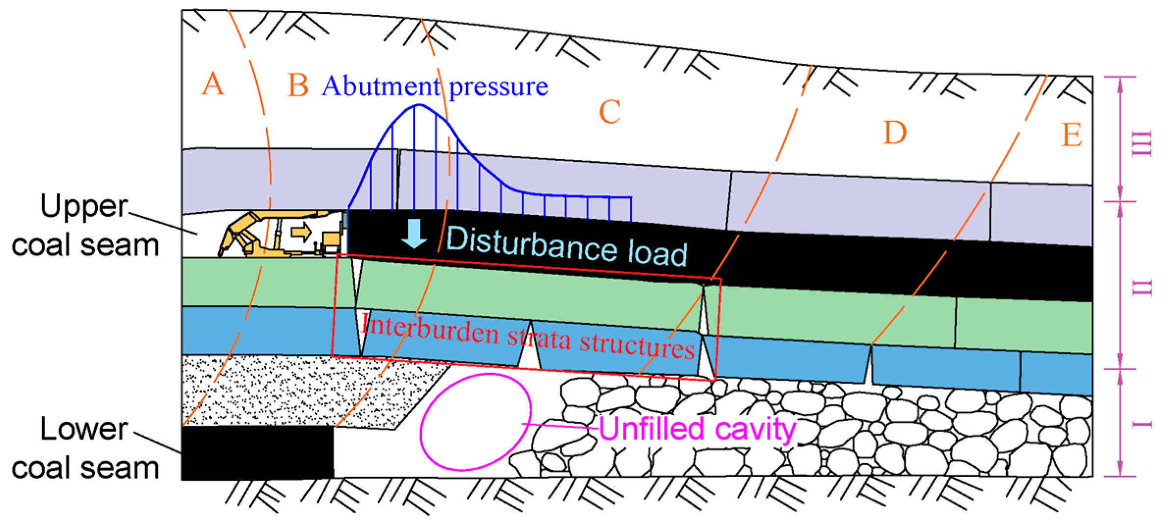
2.1.2. New Characteristic of the VBS in Upward Mining—Disturbance

As shown in Figure 1, the VBS above the unfilled cavity is stable under undisturbed conditions. However, when subject to the abutment pressure disturbance load caused by the upward mining working face, there is a risk that these interburden strata structures might become unstable. Overall, the instability of interburden strata structures is completely different from the instability of the traditional VBS, primarily in the following aspects: the instability inducement of interburden strata structures is the disturbance load generated by the movement of abutment pressure in the upward mining working face, whereas the instability inducement of traditional VBS relates to the internal evolution within the structures.
It can be seen that interburden strata structures are similar to traditional overburden rock structures on the longwall mining working face. Indeed, both of them can present the VBS. However, the new characteristics of the interburden strata structure were influenced by a moving disturbance load generated by upper coal seam mining. Therefore, we can establish a mechanical model of the DVBS to study the stability of the interburden strata structures during upward mining.

2.2. Establishment of the DVBS Model

Interburden strata structures are the strata structures between two coal seams in the case of upward mining. Overburden rock structures are composed of rock blocks. According to the VBS theory [27], block B and block C play crucial roles in the stability of the entire structures. These are called key rock blocks. The size of the impact of the advance abutment pressure on the upward mining working face was much larger than the length of the overburden rock strata structures of the longwall working face. Therefore, although the disturbance load exerted by the abutment pressure on the DVBS was non-uniform, the disturbance load could still be simplified as a uniform disturbance load. In summary, according to the VBS model, the DVBS model of interburden strata can be represented by Figure 3. In the figure, qa represents the load of the abutment pressure applied to the DVBS by the upward mining working face, which is called the disturbance load. Its length increases with the advancement of the upward mining working face, and its maximum length is greater than twice the length of the DVBS. q1, q2, and qr2 are distributed forces acting on the upper and lower surfaces of the block, and q1 and q2 are the loads acting on the VBS before the upper coal seam is mined, including the weight of the block. RA and RB as well as T are the shear forces and horizontal thrust force at points A and B, respectively. It is assumed that the forces distributed on each block are uniformly distributed, and the support force below block B is zero. The length of the disturbance load acting on the DVBS is b; h and li (i = 1, 2) are the height and length of the block; θ1 and θ2 are the rotation angles of block B and block C; and W1 and W2 are the subsidence of block B and block C.

2.3. Solution of the Model

Mechanical analysis of the DVBS model was carried out. Based on stress equilibrium and moment equilibrium (sum of the torques about point A and point O are both zero), the equilibrium equations of the DVBS model were obtained:
R A + R B + q r 2 l 2 q 1 l 1 q 2 l 2 q a b = 0 q 1 l 1 2 2 + q 2 l 2 l 1 + l 2 2 q r 2 l 2 l 1 + l 2 2 l 1 + l 2 R B T h W 2 a v + q a b l 1 + l 2 b 2 = 0 q 2 l 2 2 l 2 q r 2 l 2 2 l 2 l 2 R B + T W 2 W 1 + q a b l 2 b 2 = 0 ,   b l 2
R A + R B + q r 2 l 2 q 1 l 1 q 2 l 2 q a b = 0 q 1 l 1 2 2 + q 2 q r 2 l 2 l 1 + l 2 2 l 1 + l 2 R B T h W 2 a v + q a b l 2 l 1 b l 2 2 + q a l 2 l 1 + l 2 2 = 0 q 2 l 2 2 l 2 q r 2 l 2 2 l 2 l 2 R B + T W 2 W 1 + q a b l 2 b 2 = 0 ,   b > l 2
Considering the similar properties of the main roof rock beams under the same geological mining conditions, it was approximated as li = l. Thus, the solution for the DVBS model was obtained:
T = q 1 + q 2 q r 2 l 2 + q 1 b 2 2 h + W 2 2 W 1 a v R B = h W 1 a v q a b 2 2 h + W 2 2 W 1 a v l + q a b + q 2 q r 2 l 2 + W 2 W 1 q 1 + q 2 q r 2 l 2 h + W 2 2 W 1 a v R A = 2 q 1 + q 2 q r 2 l 2 + q a b 2 2 l W 2 W 1 q 1 + q 2 q r 2 l 2 + q a b 2 2 h + W 2 2 W 1 a v l , b l 2
T = q 1 + q 2 + q a q r 2 l 2 + q a b l 3 l b 2 h + W 2 2 W 1 a v R B = q 1 l q 1 + q a + q a b l 3 l b W 2 W 1 2 h + W 2 2 W 1 a v 1 2 q a l R A = q 1 l + q a b q 1 l q 1 + q a + q a b l 3 l b W 2 W 1 2 h + W 2 2 W 1 a v 1 2 q a l , b > l 2
Normally, the contact between rock blocks at both ends should be equal [26]. Therefore, the relationship between the contact height and the height and length of the block was obtained:
a v = 1 2 h l i sin   θ 1
It is known from the geometry of the block that:
W 1 = l sin   θ 1
W 2 = l sin   θ 1 + sin   θ 2
In order to further study the influence of the disturbance load on the stability of the DVBS, the disturbance load distribution coefficient (DLDC) was defined as the ratio of the length of the disturbance load acting on the DVBS to the model length, represented by j (j = b/l). The height-to-length ratio of the block, known as the lump rate, was represented by i (i = h/l). The disturbance load coefficient (DLC), represented by df (df = qa/qi), was defined as the ratio of the disturbance load to the original load acting on the VBS. Considering the actual situation, q2 is approximately equal to qr2. By substituting Equations (8)–(10) and the expressions of j, i, and df into Equations (6) and (7), the expression of the force solution equation for this model was obtained:
T = q 1 l 1 + d f · j 2 i sin θ 1 + 2 sin θ 2 R B = q 1 l 0.5 i sin θ 1 d f · j 2 + sin θ 2 i sin θ 1 + 2 sin θ 2 + d f · j R A = q 1 l 1 + 0.5 i sin θ 1 d f · j 2 sin θ 2 i sin θ 1 + 2 sin θ 2 , b l 2
T = q 1 l 1 + d f + d f j 1 3 j i sin θ 1 + 2 sin θ 2 R B = q 1 l 1 + d f + j 1 3 j d f sin θ 2 i sin θ 1 + 2 sin θ 2 1 2 d f R A = q 1 l 1 + d f · j + 1 2 d f 1 + d f + j 1 3 j d f sin θ 2 i sin θ 1 + 2 sin θ 2 , b > l 2

2.4. Stability Condition and Analysis of the Model

According to the VBS theory, the DVBS exhibits two types of instability mechanisms: rotation instability and sliding instability.

2.4.1. Condition for Rotation Instability

When the DLC and the DLDC increase to a certain extent, the horizontal thrust also increases accordingly. When the horizontal thrust increases to a certain value, the corner position of the block is the first to be destroyed, causing the instability of the block, which is called rotation instability. Furthermore, introducing the influencing factor of the environment of the DVBS, the conditions for the DVBS not to undergo rotation instability are:
T a η c η e σ c
where a represents the contact area of the block per unit width, and ηc is the corner compression factor; ηc is set to 0.3. ηe is defined as the horizontal thrust comprehensive environmental influence factor, which represents the weakening effect of the environment on the compressive strength and is determined through experiments [19].
By substituting Equations (11) and (12) into Equation (13a) and rearranging them, Equation (13b) is obtained. Therefore, if the DVBS does not undergo rotation instability, the DLC and DLDC must meet the following conditions:
d f · j 2 1 2 q 1 η c η e σ c i sin θ 1 + 2 sin θ 2 i sin θ 1 1 ,   b l 2 d f · 2 2 j 2 1 2 q 1 η c η e σ c i sin θ 1 + 2 sin θ 2 i sin θ 1 1 ,   b > l 2
When both the DLC and the DLDC are zero, Equation (13b) is completely consistent with the calculation results of the VBS theory. In Equation (13b), “df·j2” and “df·[2 − (2 − j)2]” are used to characterize the dimensionless parameters that represent the upward mining disturbance. Additionally, the magnitude and distribution range of disturbance loads are clarified and defined as disturbance factors. The right side of the equation represents the block parameters of the DVBS, which characterize the critical conditions under which rotation instability does not occur in the DVBS. This equation establishes the relationship between the parameters of the DVBS and the disturbance load during rotation instability.

2.4.2. Analysis of Rotation Instability

Selecting relevant research results for parameter values [27], let θ1 = 2°, θ2 = 0.5°, i = 0.5, q1 = 0.5 MPa, l = 10 m, ηc = 0.3, ηe = 1; it is possible to analyze the influence of different lump rates, the DLC, and the DLDC on the rotation instability of the block.
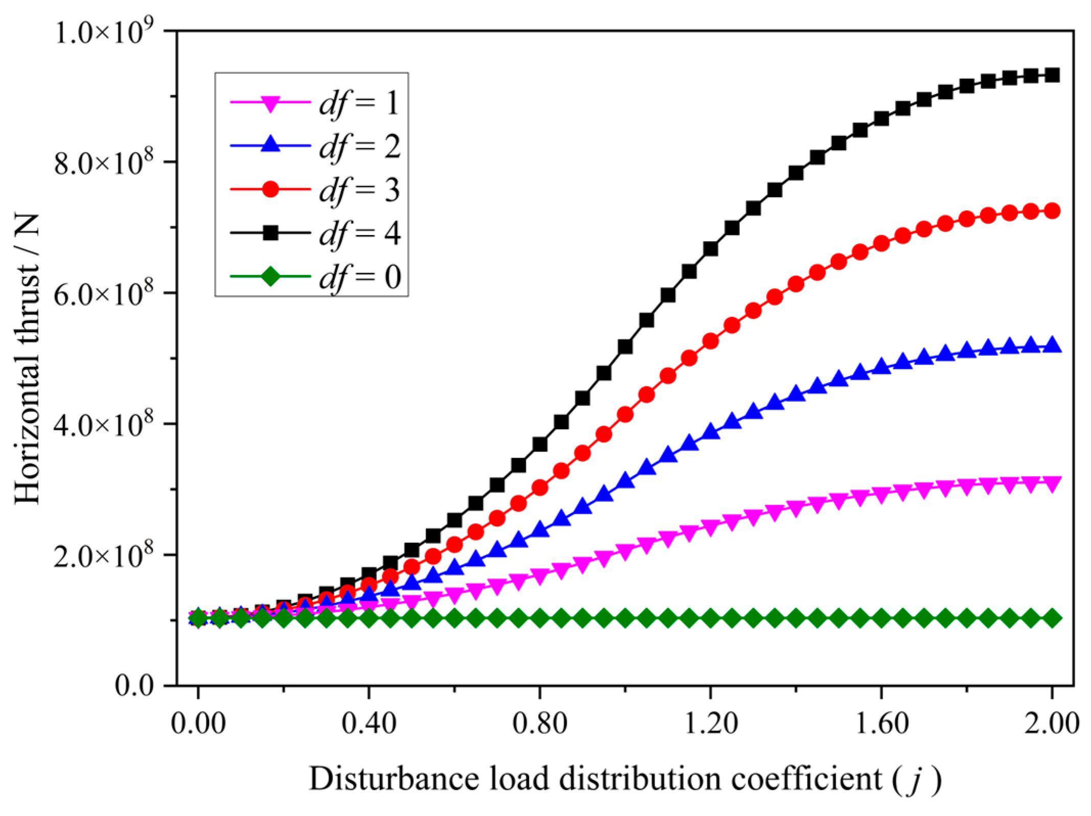
  • Relationship between DLDC and Horizontal Thrust
Using Equations (11) and (12), the horizontal thrust and the DLDC are calculated for DLCs (df) = 0, 1, 2, 3, and 4. Figure 4 presents the relationship between the DLDC and horizontal thrust.
As shown in Figure 4, when df = 0, the disturbance load on the DVBS model is zero. The corresponding calculation results are consistent with the calculation results of the VBS theory, verifying the correctness of the model. When df ≠ 0, as the DLDC increases, the horizontal thrust shows an increasing trend of “fast first, slow later,” and the curve exhibits an “S” shape. The larger the DLC is, the faster the change trend of the “S” curve with the increase in the DLDC will be.
2.
Effect of the Lump Rate on the Rotation Instability
Based on the above parameter calculations, Figure 5 shows the relationship between the lump rate and the critical DLC for DLDC (j) = 1 and DLDC = 2, with the uniaxial compressive strengths of rock strata structures standing at 65 MPa, 75 MPa, 85 MPa, 95 MPa, and 105 MPa.
As shown in Figure 5, when the DVBS has the same uniaxial compressive strength, the critical DLC for rotation instability increases with increasing lump rate and follows a quadratic function distribution. Under the same uniaxial compressive strength of the DVBS, the critical DLC required for instability when the disturbance load acts on two blocks is much smaller than the critical DLC required when the disturbance load only impacts block B. The larger the lump rate, the greater the disturbance load required for rotation instability. When the lump rate remains the same, the uniaxial compressive strength of the DVBS grows larger, and the greater the disturbance load required for rotation instability becomes. This is consistent with the known fundamental law.
3.
Effect of the Disturbance Load on the Rotation Instability
Derived based on the above parameters, the critical DLC and the corresponding DLDC for calculating uniaxial compressive strength according to Equation (13b) at 65 MPa, 75 MPa, 85 MPa, 95 MPa, and 105 MPa are shown in Figure 6. The logarithmic coordinate axis is used on the vertical axis of the figure to represent its rapid rate of change. As the DLDC increases, the required disturbance load for the rotation instability of the DVBS decreases rapidly, showing a power function decreasing trend. This indicates that when the disturbance load is small, a significant disturbance load is needed to cause DVBS instability. When the DLDC is less than 0.5, a large disturbance load is required for rotation instability. However, when the DLDC is greater than 0.5, as the range of the distribution load increases, the required disturbance load for rotation instability starts to decrease slowly. The disturbance load acts entirely on the DVBS, making it more prone to rotation instability.

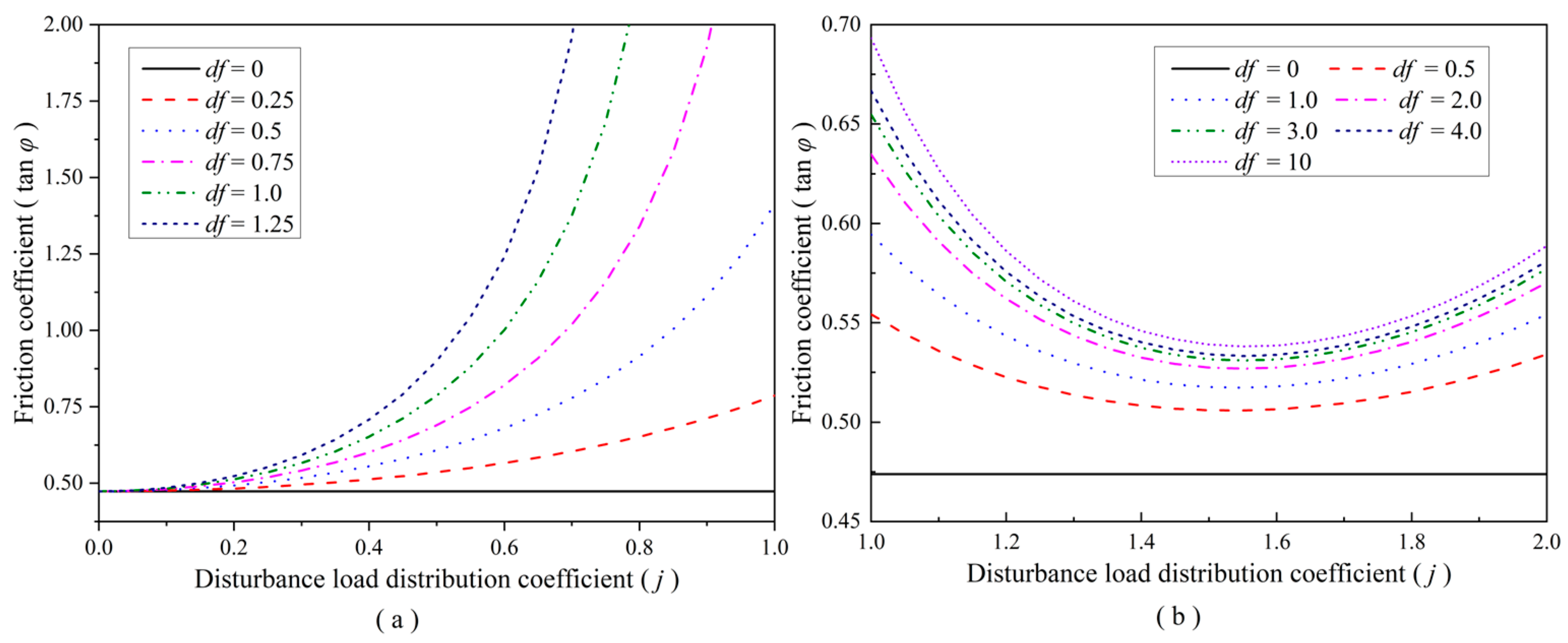
2.4.3. Condition for Sliding Instability

In addition to rotation instability, the key block of the DVBS may also undergo sliding instability during the transformation process. The maximum shearing force is located at point A, as indicated in Figure 3. Therefore, in order to prevent the block sliding instability at this location, the following conditions must be satisfied:
T · η e · tan φ R A
By substituting Equations (11) and (12) into Equation (14a) and rearranging them, the condition under which sliding instability does not occur in the DVBS is obtained:
1 d f · j 2 + 1 2 η e tan φ i sin θ 2 i sin θ 1 + 3 sin θ 2 ,   b l 2 d f · j + 1 2 2 + d f d f + 1 + d f j 1 3 j η e tan φ + sin θ 2 i sin θ 1 + 2 sin θ 2 ,   b > l 2
The parameters in the equation have the same meanings as mentioned previously. When both the DLC and the DLDC are zero, the equation is completely consistent with the calculation results of the VBS theory. Equation (14b) establishes the relationship between the parameters of the DVBS and the disturbance load under the condition of sliding instability. In Equation (14b), the left side of the equation only contains the DLC and DLDC, which represent the disturbance factors. The right side of the equation represents the block parameters of the DVBS, which characterize the critical conditions under which sliding instability does not occur in the DVBS. This equation establishes the relationship between the parameters of the DVBS and the disturbance load during sliding instability.

2.4.4. Analysis of Sliding Instability

Selecting the relevant research results for parameter values [27], let θ1 = 2°, θ2 = 0.5°, i = 0.5, q1 = 0.5 MPa, ηc = 0.3, ηe = 1. We now analyze the impact of different lump rates, the DLC, and the DLDC on the instability of block sliding.
  • Effect of the Lump Rate on Sliding Instability
According to the above parameters and Equation (14b), the relationship between the lump rate and the friction coefficient is calculated for DLC = 0.75, with varying DLDCs of 0, 0.25, 0.5, 0.75, 1, 1.25, 1.5, and 1.75.
As shown in Figure 7, when the DLC and the DLDC are both zero, the calculation results and trends of the lump rate and friction coefficient in this DVBS model are the same as those in the traditional VBS model. When the DLDC is constant, the friction coefficient has a linear relationship with the lump rate. As the lump rate increases, the friction coefficient required to ensure the stability of the DVBS without sliding increases.
2.
Effect of Disturbance load on the Sliding Instability
Figure 8 shows the relationship between the DLDC and the friction coefficient for DLCs of 0, 0.25, 0.5, 0.75, 1, 1.25, 2, 3, 4, and 10.
As shown in Figure 8, when bl2, with the increase in the DLC, the required friction coefficient for point A to maintain stability in Figure 3 increases. Under the same DLC, the required friction coefficient for maintaining the stability of the DVBS increases rapidly with the increase in the DLDC following a power function. The larger the DLC, the greater the influence of the variation in the DLDC on the required friction coefficient for maintaining the stability of the DVBS. When b > l2, the required friction coefficient for point A to maintain stability decreases rapidly before slowly increasing again. The main reason for this phenomenon is that, when the disturbance load generated by upward mining acts on block C, block B completes its reverse rotation, and block C begins instead to rotate in reverse. The corresponding horizontal thrust first increases slowly and then increases rapidly before increasing slowly again. The range of variation in the required friction coefficient for maintaining structural stability is relatively small. When the DLC increases from 0.5 to 10, the maximum required friction coefficient only increases from 0.55 to 0.68. From Figure 8, it can be observed that when the disturbance load spans two blocks, the maximum required friction coefficient for maintaining the stability of the DVBS is highest. In this scenario, the coefficient is greatly affected by the variation in the disturbance load, making it the most prone to instability.

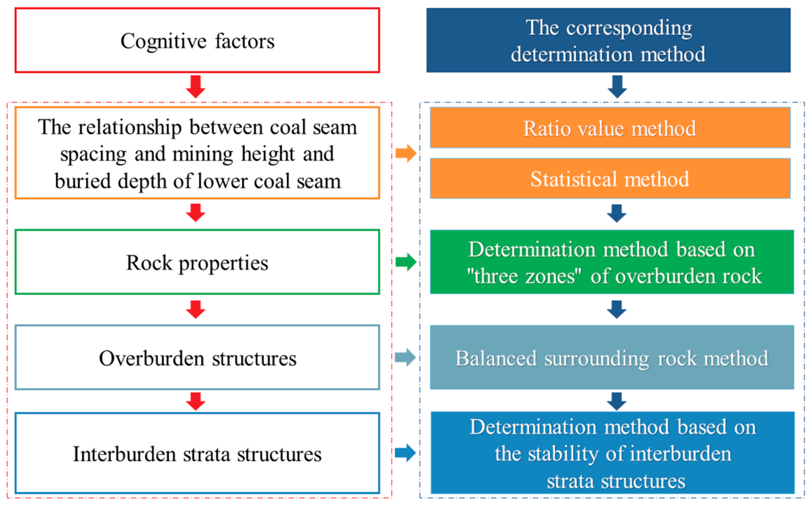
3. Determination Method for Upward Mining Based on Stability of the DVBS

Under the influence of the abutment pressure on the upward mining working face, the instability conditions of the DVBS can be calculated. If the load is too large, the structures become unstable, leading to the collapse of personnel and equipment in the upward mining working face. Conversely, if the load is within a safe range, upward mining can be carried out safely. Therefore, a feasibility determination method for upward mining can be proposed based on the aforementioned model.

3.1. Proposal of the Method

Based on the DVBS model of interburden strata, a feasibility determination method for upward mining is proposed, with “the stability of the DVBS” as the core. The specific steps are as follows:
Step 1: Obtain the rock column and basic physical and mechanical parameters based on the geological information of the mining area, including the mining height of the lower coal seam, the elastic modulus, thickness, bulk density, and tensile strength of interburden strata.
Step 2: Use the key stratum theory [27] to calculate the loads q1 and q2 acting on the rock strata structures before beginning upward mining:
q 1 = q 2 = q n 1 = E 1 h 1 3 γ 1 h 1 + γ 2 h 2 + + γ i h i + + γ n h n E 1 h 1 3 + E 2 h 2 3 + + E i h i 3 + + E n h n 3
where hi, γi, Ei, and Rti represent the thickness, volume weight, elastic modulus, and tensile strength of the i-th rock stratum, respectively (i = 1, 2, …, n).
Step 3: According to the key stratum theory and the determination equation of the controlling stratum [27], determine the position of the rock stratum where the VBS is located. Based on the mining pressure observation results or the periodic weighting step calculation equation [20], determine the length of the VBS:
q n + 1 < q n γ n + 1 i = 1 n E i h i 3 < E n + 1 h n + 1 2 i = 1 n h i γ i l j + 1 > l j
where lj is the breaking span of the j-th hard rock stratum (j = 1, 2, …, k).
Step 4: Calculate the propagation and attenuation of disturbance load in rock layers using the following equation [19]:
q a = 0.637 k i γ D arctan x 0 l 0 z 4 x 0 4 + l 0 2 + 4 z 2 + l 0 z 4 x 0 4 + l 0 2 + 4 z 2 l 0 2 + 4 z 2 2 x 0 l 0 2 + 4 z 2
where x0 and l0 are, respectively, the width and length of the abutment pressure of the upward mining working face, m; ki is the abutment pressure concentration coefficient; and z is the depth from the floor of the upward mining coal seam to the upper surface of the DVBS, m.
Step 5: According to the stability determination Equations (13b) and (14b) for the DVBS, determine whether upward mining causes instability in the DVBS to assess the feasibility of upward mining.
Due to the requirements of the VBS model, which serves as the basic model, that the overburden strata include hard rock strata and form load-bearing structures [27], both the DVBS model proposed based on the VBS model and its corresponding determination method are also subject to the same prerequisite conditions. In other words, this method is applicable to situations where the main roof rock stratum is thick and hard, as well as situations without a false roof or immediate roof. These situations are quite common in longwall mining; thus, this method is universally applicable.

3.2. Application of the Method

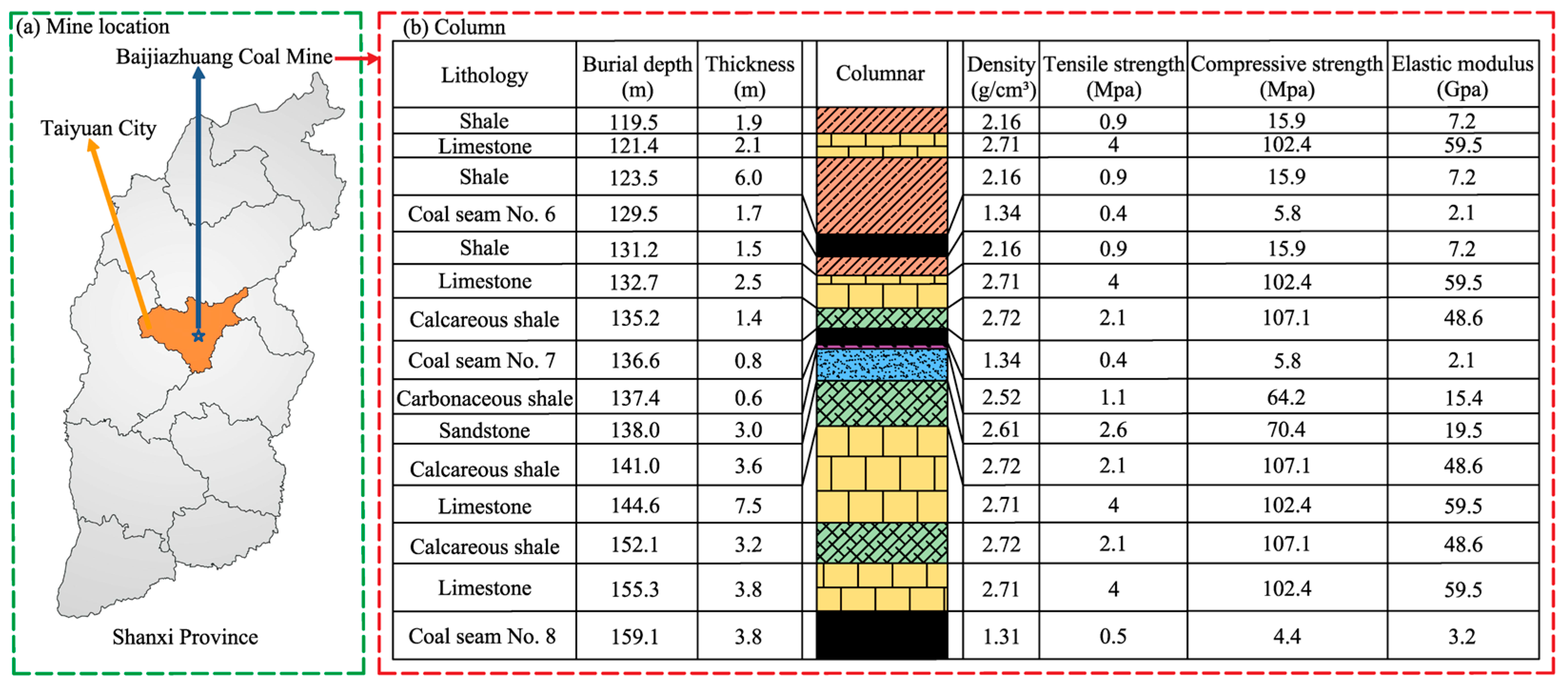
3.2.1. Engineering Background

Due to historical reasons, Baijiazhuang Coal Mine conducted underground mining on coal seam No. 8 with a thickness of 3.8 m. Then, upper coal seam No. 6 was mined using the upward mining method. After the completion of mining coal seam No. 6, it was decided to mine coal seam No. 7 as well. Coal seam No. 7 is located between coal seams No. 6 and No. 8, with a thickness of 0.7–1.3 m and an average thickness of 0.8 m. It is buried at a depth of 95.4–177.8 m, with an average depth of 136.6 m. The distance between coal seams No. 7 and No. 6 above is 5.4 m, and the distance to coal seam No. 8 below is 22.7 m. The interburden strata between coal seams No. 7 and No. 8 are mainly composed of medium–hard and hard rocks. The structures of the surrounding rock strata of the adjacent coal seam roof and floor, as well as the physical and mechanical parameters of the surrounding rock strata, are shown in Figure 9.

3.2.2. Feasibility Determination for Upward Mining

In the overburden strata, there are hard rock strata that can form stratified structures, and the proposed new method is applicable. According to the actual working conditions of the Baijiazhuang Coal Mine, when the upper coal seam working face passes through the area affected by interburden strata structures, the concentration coefficient of the advance abutment pressure on the working face is taken as 1.5, the environmental influence factor is taken as 0.8, and the rotation angle is taken as 2°. Combining this information with the results shown in Figure 9, according to the calculation Equation (16) of key strata [27], we determined that limestone strata with thicknesses of 3.8 m and 7.5 m could form a VBS. The rock block lengths of the VBS are 12.85 m and 16.32 m, respectively, and the lump rates are 0.30 and 0.46, respectively.
According to Equation (17), the disturbance loads caused by advance abutment pressure on the DVBS between the upper and lower limestone strata are 3 × 10⁶ N and 7 × 10⁵ N, respectively. Then, it can be inferred that the disturbance factors of the two limestone strata are 2.14 and 1.26, respectively. They are much smaller than the critical values of rotation instability calculated based on Equation (13b) for determining rotation instability, which are 4.44 and 4.08. Therefore, there is no occurrence of rotation instability in the DVBS. According to the calculation based on Equation (14b) to determine sliding instability, the friction coefficients for the DVBS of the upper and lower strata, where no sliding instability occurs, are 0.78 and 1.22, respectively. Interpreting the actual measurements and research [37], we find that the range of friction coefficients for the roof rock strata structures spans from 0.6 to 1.24. The primary load-bearing structures are formed by the upper 7.5 m limestone, and the critical friction coefficient for the DVBS in the upper part, where no sliding instability occurs, is 1.22. This friction coefficient value is within the upper limit, indicating a low probability of sliding instability. Therefore, based on the above, coal seam No. 7 can be mined upward.

3.2.3. Comparison with Traditional Determination Methods

The feasibility of upward mining for coal seam No. 7 was assessed using the traditional ratio value method, statistical method, and “three-zone” method. The results obtained from the balanced surrounding rock method were also included for comparison.
The rock strata between coal seams No. 7 and No. 8 are hard rock strata, and the critical mining influence factor is set at 8 [4]. The actual mining influence factor for upward mining of coal seam No. 7 is 5.7, which is less than its critical mining influence factor of 8. Additionally, the actual OB/IB value is 6.3, which is also lower than the critical value of 7. Therefore, according to the ratio value method, it is determined that coal seam No. 7 cannot be mined upward.
According to Equation (1), the minimum coal seam spacing required for upward mining is calculated to be 20.6 m, which is less than the actual coal seam spacing of 21.7 m. Therefore, based on the statistical method, it is determined that coal seam No. 7 can be mined upward.
According to Equation (2), the minimum coal seam spacing required for upward mining is 15.8 m, which is lower than the actual coal seam spacing of 21.7 m. Therefore, based on the “three-zone” method, it is determined that coal seam No. 7 can be mined upward.
The bulking coefficient K1 is taken to be 1.3 [27]. The balanced rock stratum is limestone, with a thickness hp of 7.5 m. According to Equation (3), the calculated balanced height of the surrounding rock is 20.2 m, which is lower than the coal seam spacing of 21.7 m. Therefore, it is determined coal seam No. 7 can be mined using the balanced surrounding rock method.
In summary, the ratio value method determines that coal seam No. 7 cannot be mined via upward mining, while the statistical method, the “three-zone” method, and the balanced surrounding rock method determine that coal seam No. 7 can be mined using upward mining. The results of the new method proposed in this paper are consistent with those of statistical methods, the “three-zone” method, and the balanced surrounding rock method. This validates the accuracy of the new method. Moreover, the result of the ratio value method indicates that it is not feasible to mine the seam, while the results of the statistical method and the balanced surrounding rock method indicate feasibility, even if the values remain in a critical state. In practical mining, these determination results may misguide mining and increase the risk of uncertainty. The reason for these phenomena is that these methods are essentially empirical and cannot accurately reflect the mechanical state of the rock structures. The new method reflects stability through the mechanical state of the rock structures, resulting in more accurate and reliable results being obtained. It has a positive significance for helping coal mines make correct decisions in production practice.

4. Stability Simulation of Interburden Strata Structures in Upward Mining

4.1. Simulation Program

To verify the accuracy of the DVBS model of interburden strata and the feasibility determination method of upward mining, a physical simulation experiment and numerical simulation method were used to study the stability of the interburden strata structures in coal seam No. 7’s upward mining.
The physical simulation experiment used a plane-strain-simulating test bench with dimensions of 3.0 m × 2.5 m × 0.2 m. The geometric similarity ratio is 100:1, the time similarity ratio is 10, and the density similarity ratio is 1.6. Quartz sand is used as the aggregate for similar materials, lime and gypsum are used as cementitious materials, borax is used as a retarding agent, and mica powder is used to create layering [38]. The mining length of the model is 110 mm, and mining of 3 cm is carried out every 0.8 h, which is equivalent to a daily advance of 6 m along the working face. The experimental model is shown in Figure 10a.
Using the UDEC5.0 software for numerical simulation, the computational model is shown in Figure 10b. The model has a length of 400 m and a height of 50 m. Each working face of the coal seam has a continuous advance distance of 200 m. There are 100 m coal pillars on both sides of the model. The lower and lateral parts of the model adopt displacement boundaries, while the upper portion has a compensating load of 2.99 MPa. The Mohr–Coulomb constitutive model was used for the analysis.
Mining plan: First, mine the lower coal seam, No. 8. After the stability of the rock strata movement is ensured, proceed with mining the upper coal seam, No. 6. Finally, mine the middle No. 7 coal seam.

4.2. Evolution of Interburden Strata Structures

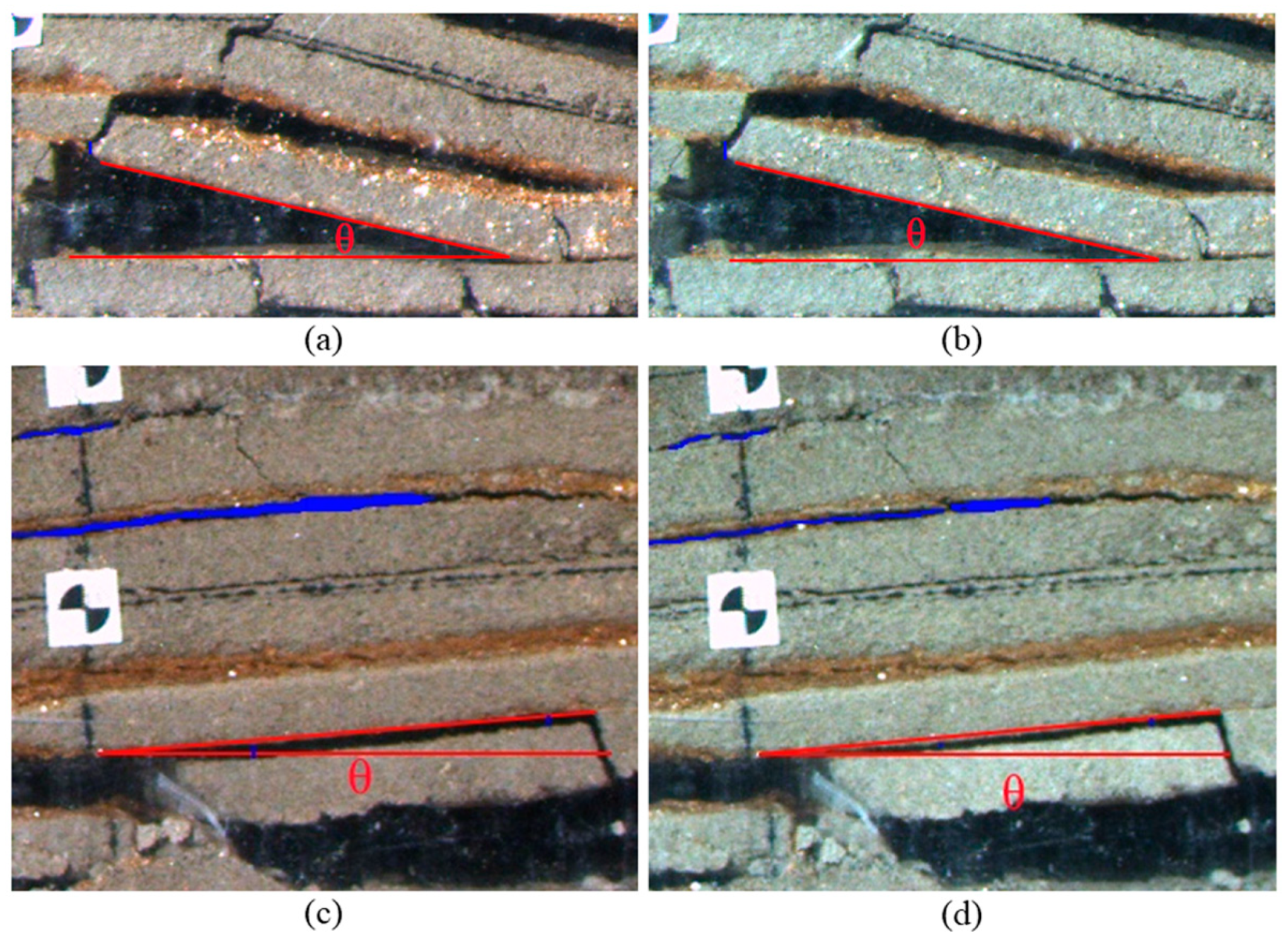
4.2.1. Result of Physical Simulation

In order to study the movement of the interburden strata structures caused by upward mining, the displacement and rotation angles of the interburden strata structures were measured. Figure 11 illustrates the movement of interburden strata structure blocks before and after upward mining.
According to Figure 11a,b, after the mining of coal seam No. 8, the angle between the left rock strata structures block and the horizontal direction was 13.5°. After coal seam No. 6 had been mined, this block did not move. Conversely, after mining coal seam No. 7, the angle between this block and the horizontal direction decreased by a value between 0.9° to 12.6°, and the rock strata structures subsided by about 5 mm. Therefore, we concluded that the upward mining of coal seam No. 6 had almost no impact on the left interburden strata structures of the goaf of coal seam No. 8 coal, while there was significant subsidence and rotation of the interburden strata structures during the upward mining of coal seam No. 7.
As shown in Figure 11c,d, during the upward mining of coal seam No. 7, the right interburden strata structures rotated by 0.2° and subsided by 4.7 mm. The separation between the interburden strata (shown in blue) was noticeably reduced, with reductions of 3.1 mm and 1.8 mm. The upward mining of coal seam No. 7 caused compaction of the interburden strata and rotation and subsidence of the rock strata structures, but no instability or failure occurred.

4.2.2. Result of Numerical Simulation

A further numerical simulation was used to study the movement and stability of interburden strata structures during the upward mining of coal seam No. 7. Figure 12 presents the simulated results of the evolution of interburden strata structures below coal seam No. 7 after the upward mining of coal seams No. 6 and No. 7.
As shown in Figure 12, after the mining of coal seam No. 8 in the lower part, stable interburden strata structures were formed between coal seams No. 7 and No. 8. After the upward mining of coal seam No. 6, interburden strata structures were slightly compressed due to the influence of the mining above. The separation distance near the observation point decreased from 17 cm to 16 cm, while the angle θ between the rock block and the horizontal direction remained unchanged at 6.8°. After the upward mining of coal seam No. 7, the rock blocks in the interburden strata structure sank and rotated. The separation distance near the observation point decreased from 16 cm to 14 cm, and the angle between the rock block and the horizontal direction decreased from 6.8° to 5.7°. The numerical simulation study showed that the upward mining of coal seam No. 7 caused the sinking and rotation of the blocks in the interburden strata structures, but the structures remained stable and no instability occurred. The results of physical simulation experiments and numerical simulation are consistent, verifying the correctness of feasibility determination for upward mining.

5. Conclusions

This paper establishes a DVBS mechanics model of interburden strata in upward mining. It deduces the instability conditions and mechanisms of this model and establishes a quantitative relationship between the disturbance factor of upward mining and rock structure parameters such as the lump rate, rotation angle, and uniaxial compressive strength. It proposes a feasibility determination method for upward mining based on the stability of the DVBS and applies it to upward mining in coal seam No. 7 of Baijiazhuang Coal Mine. The stability of the interburden strata structures in coal seam No. 7 during upward mining was studied using physical simulation and numerical simulation. The results are as follows:
  • Together, the DLC and the DLDC form the disturbance factor in upward mining, which affects the stability of the DVBS. There are two mechanisms of instability in the DVBS during upward mining: rotation instability and sliding instability. When the disturbance load crosses the key blocks of the DVBS, the DVBS is most likely to experience sliding instability. When the disturbance load is entirely applied to the key blocks of the DVBS, rotation instability is more likely to occur.
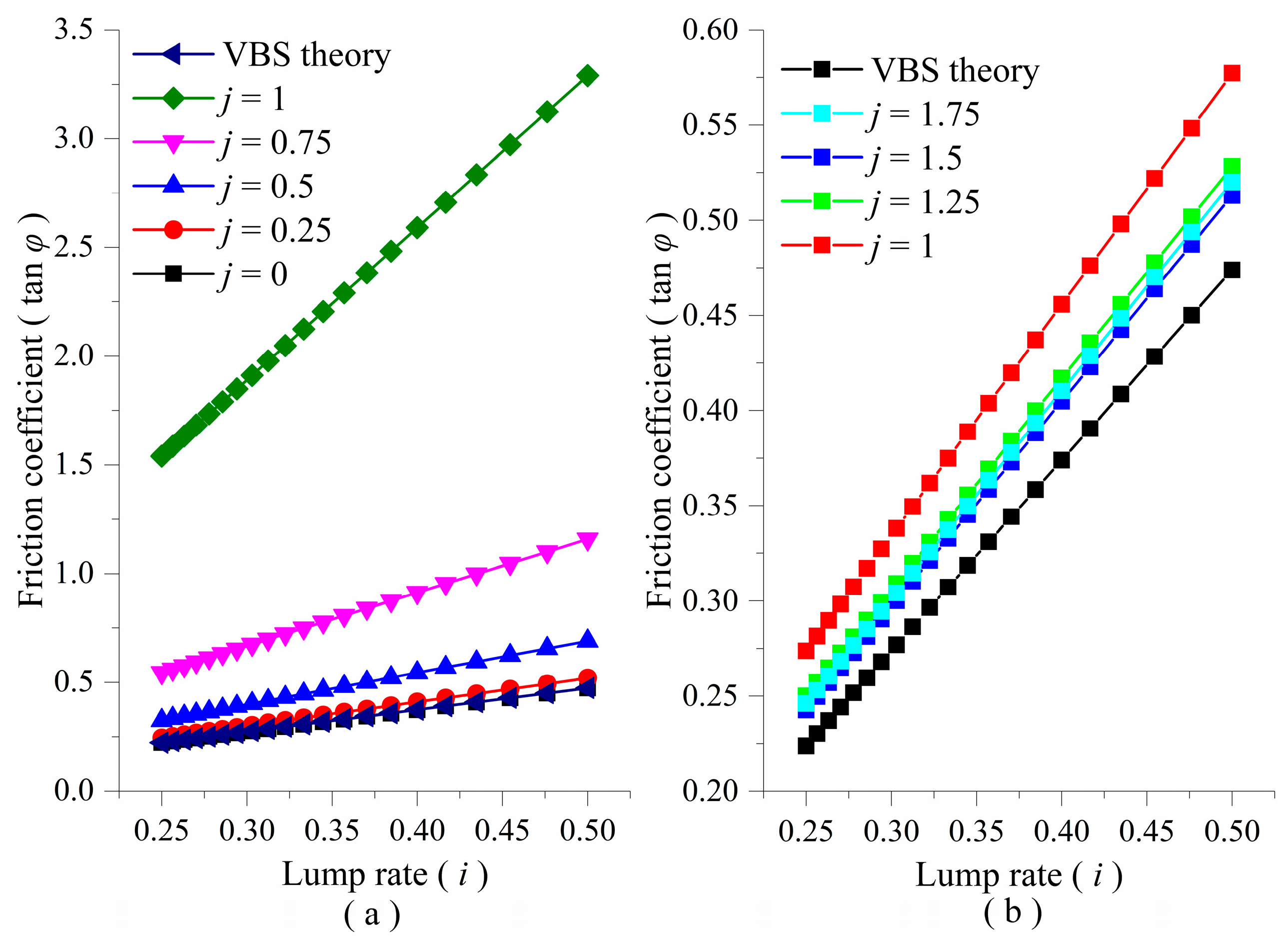
  • Using the proposed method, it is determined that the 7.5 m limestone in the interburden strata structures is the primary load-bearing stratum, and its disturbance factor in upward mining is 2.14, which is much smaller than the critical value of 4.44 for rotation instability, indicating that rotation instability will not occur. The critical friction coefficient of this DVBS is 1.22, which is close to the upper limit of the empirical range of friction coefficients from 0.6 to 1.24, indicating a low probability of sliding instability. Therefore, it is determined that the interburden strata structures are stable and upward mining can be conducted in coal seam No. 7. The results obtained using this method differ from those obtained using the ratio value method but are consistent with the results obtained using the statistical method, “three-zone” method, and balanced surrounding rock method.
  • Simulation results show that upward mining would cause the sinking, rotation, and compaction of interburden strata structures. After upward mining in coal seam No. 7, the key blocks of the interburden strata structures rotated by 0.2° to 1.1°, with a maximum subsidence of 500 mm and a maximum separation compaction of 310 mm. Although there was movement in the interburden strata structures, it remained stable, further verifying the accuracy and applicability of this new method.
When there are rock strata structures in the interburden and the rock strata structures form a VBS, the new method will be applicable. Compared to traditional determination methods, the proposed model and method reflect the effect of upward mining disturbance, resulting in more accurate and reliable results. It has a positive significance in terms of improving the safety of upward mining practices.

Author Contributions

Conceptualization, Y.Z. and Y.W.; methodology, Y.Z.; software, Y.W., S.Z. and B.C.; validation, Y.Z., S.Z. and C.Z.; investigation, Z.Z. and B.C.; resources, G.F.; writing—original draft preparation, B.C. and Y.W.; writing—review and editing, C.Z. and S.Z.; project administration, G.F. and Z.Z.; funding acquisition, G.F. All authors have read and agreed to the published version of the manuscript.

Funding

This research was funded by the National Natural Science Foundation of China (Nos. 52004172, 52374100, 52304150, 51925402, 52304149); a China Postdoctoral Science Foundation-funded project (2020M682215); The Fundamental Research Programs of Shanxi Province (No. 202103021223093); the Research Fund of The State Key Laboratory of Coal Resources and Safe Mining (SKLCRSM22KF010); and the Scientific and Technological Innovation Programs of Higher Education Institutions in Shanxi (No. 2022L054).

Data Availability Statement

Data supporting reported results can requested from the author.

Acknowledgments

The authors are grateful for the guidance provided by Yunlou Du in the physical simulation experiment.

Conflicts of Interest

The authors declare no conflict of interest.

References

  1. Zhang, Y.; Feng, G.; Zhang, M.; Ren, H.; Bai, J.; Guo, Y.; Jiang, H.; Kang, L. Residual coal exploitation and its impact on sustainable development of the coal industry in China. Energy Policy 2016, 96, 534–541. [Google Scholar] [CrossRef]
  2. Liu, Y.; Cheng, J.; Jiao, J.; Meng, X. Feasibility study on multi-seam upward mining of multi-layer soft-hard alternate complex roof. Environ. Earth Sci. 2022, 81, 424. [Google Scholar] [CrossRef]
  3. Marinina, O.; Nechitailo, A.; Stroykov, G.; Tsvetkova, A.; Reshneva, E.; Turovskaya, L. Technical and Economic Assessment of Energy Efficiency of Electrification of Hydrocarbon Production Facilities in Underdeveloped Areas. Sustainability 2023, 15, 9614. [Google Scholar] [CrossRef]
  4. Ma, L.; Wang, L.; Zhang, D.; Liu, Y.; Liu, J.; Zhang, T.; OuYang, G. Application and Study on Feasibility of Near Distance Coal Seam Group Ascending Mining. J. Hunan Univ. Sci. Technol. (Nat. Sci. Ed.) 2007, 22, 1–5. [Google Scholar]
  5. Zhang, H.; Han, J.; Hai, L.; Li, M.; Qiao, H. Study on closed multiple-seam in the ascending mining technology. J. Min. Saf. Eng. 2013, 30, 63–67. [Google Scholar]
  6. Wu, X.; Wang, J.; Chen, S.; Zhang, Y.; Bu, Q. Regulation principle and stability control of plastic zone in repeated mining roadway. Rock Soil Mech. 2022, 43, 205–217. [Google Scholar] [CrossRef]
  7. Ellenberger, J.L.; Chase, F.E.; Mark, C. Using Site Case Histories of Multiple Seam Coal Mining to Advance Mine Design. In Proceedings of the 22nd International Conference on Ground Control in Mining, Morgantown, WV, USA, 5–7 August 2003. [Google Scholar]
  8. Liu, T. The possibility of using the upward minging method. J. China Coal Soc. 1981, 1, 18–29. [Google Scholar]
  9. Yavuz, H. An estimation method for cover pressure re-establishment distance and pressure distribution in the goaf of longwall coal mines. Int. J. Rock Mech. Min. Sci. 2004, 41, 193–205. [Google Scholar] [CrossRef]
  10. Rashed, G.; Slaker, B.; Murphy, M. Exploration of Limestone Pillar Stability in Multiple-Level Mining Conditions Using Numerical Models. Min. Metall. Explor. 2022, 39, 1887–1897. [Google Scholar] [CrossRef]
  11. Gilbride, L.J.; Agapito, J.F.T.; Hollberg, K.F. Time-dependent stability implications for planned two-seam mining at the OCI Wyoming, LP, Big Island trona mine. In Proceedings of the 38th US Rock Mechanics Symposium (DC Rocks 2001), Washington, DC, USA, 7–10 July 2001; pp. 1539–1546. [Google Scholar]
  12. Zhang, K. Remining coal seam left in caving zone. Coal Min. Technol. 1999, 1, 16–17+62. [Google Scholar]
  13. Peng, S. Coal Mine Ground Control, 1st ed.; John Wiley & Sons Inc.: Hoboken, NJ, USA, 1978; pp. 37–44. [Google Scholar]
  14. Wu, B.; Deng, Z.; Feng, Y.; Li, F. Analysis of the influence of interlayer rock on ascending mining under special conditions. J. China Coal Soc. 2017, 42, 842–848. [Google Scholar] [CrossRef]
  15. Wu, X.; Wang, S.; Tian, C.; Ji, C.; Wang, J. Failure mechanism and stability control of surrounding rock of docking roadway under multiple dynamic pressures in extrathick coal seam. Geofluids 2020, 2020, 8871925. [Google Scholar] [CrossRef]
  16. Wu, X.; Liu, H.; Li, J.; Guo, X.; Lv, K.; Wang, J. Temporal-spatial evolutionary law of plastic zone and stability control in repetitive mining roadway. J. China Coal Soc. 2020, 45, 3389–3400. [Google Scholar] [CrossRef]
  17. Suchowerska, A.M.; Merifield, R.S.; Carter, J.P. Vertical stress changes in multi-seam mining under supercritical longwall panels. Int. J. Rock Mech. Min. Sci. 2013, 61, 306–320. [Google Scholar] [CrossRef]
  18. Feng, G. Study on the Theory and Its Application of Upward Mining of Left-Over Coal. Ph.D. Thesis, Taiyuan University of Technology, Taiyuan, China, 2011. [Google Scholar]
  19. Feng, G. The Theory and Its Practice of the Upward Mining of the Left-Over Coal, 1st ed.; China Coal Industry Publishing House: Beijing, China, 2010; pp. 55–67. [Google Scholar]
  20. Jiang, Y.; Yang, Y.; Ma, Z.; Li, Y. Breakage mechanism of roof strata above widespread mined-out area with roadway mining method and feasibility analysis of upward mining. J. China Coal Soc. 2016, 41, 801–807. [Google Scholar] [CrossRef]
  21. Malan, D. Manuel Rocha Medal Recipient Simulating the time-dependent behaviour of excavations in hard rock. Rock Mech. Rock Eng. 2002, 35, 225–254. [Google Scholar] [CrossRef]
  22. Lyashenko, V.I.; Andreev, B.; Dudar, T. Substantiation of mining-technical and environmental safety of underground mining of complex-structure ore deposits. Min. Miner. Depos. 2022, 16, 43–51. [Google Scholar] [CrossRef]
  23. Pappas, D.M.; Mark, C. Behavior of Simulated Longwall Gob Material, 1st ed.; Bureau of Mines, US Department of the Interior: Washington, DC, USA, 1993; Volume 9458, pp. 46–55.
  24. Bakun-Mazor, D.; Hatzor, Y.H.; Dershowitz, W.S. Modeling mechanical layering effects on stability of underground openings in jointed sedimentary rocks. Int. J. Rock Mech. Min. Sci. 2009, 46, 262–271. [Google Scholar] [CrossRef]
  25. Brady, B.H.; Brown, E.T. Rock Mechanics: For Underground Mining; Springer Science & Business Media: Berlin/Heidelberg, Germany, 2006. [Google Scholar]
  26. Qian, M.; Miao, X.; He, F. Analysis of key block in the structure of voussoir beam in longwall mining. J. China Coal Soc. 1994, 32, 557–563. [Google Scholar]
  27. Qian, M.; Xu, J.; Wang, J.; Wu, Y. Rock Pressure and Strata Control, 3rd ed.; Publishing House of China University of Mining and Technology: Xuzhou, China, 2020; pp. 71–104. [Google Scholar]
  28. Song, Z. Practical Ground Pressure Control, 1st ed.; China University of Mining and Technology Press: Xuzhou, China, 1988; pp. 32–44. [Google Scholar]
  29. Liu, C.; Li, H.M.; Mitri, H.; Jiang, D.J.; Li, H.G.; Feng, J.F. Voussoir beam model for lower strong roof strata movement in longwall mining—Case study. J. Rock Mech. Geotech. Eng. 2017, 9, 1171–1176. [Google Scholar] [CrossRef]
  30. Li, Z.; Xu, J.L.; Ju, J.F.; Zhu, W.B.; Xu, J.M. The effects of the rotational speed of voussoir beam structures formed by key strata on the ground pressure of stopes. Int. J. Rock Mech. Min. Sci. 2018, 108, 67–79. [Google Scholar] [CrossRef]
  31. Vervoort, A. Long-term impact of coal mining on surface movement: Residual subsidence versus uplift. Min. Rep. Glückauf 2020, 156, 136–141. [Google Scholar]
  32. Newman, D.; Hutchinson, A.J.; Mason, D.P. Tensile fracture analysis of a thin Euler-Bernoulli beam and the transition to the voussoir model. Int. J. Rock Mech. Min. Sci. 2018, 102, 78–88. [Google Scholar] [CrossRef]
  33. Zhang, H. Study and Application on the Distribution Law of Old Goaf Residual Cavity and Void. Ph.D. Thesis, China University of Mining & Technology, Xuzhou, China, 2014. [Google Scholar]
  34. Burtan, Z.; Chlebowski, D. The Effect of Mining Remnants on Elastic Strain Energy Arising in the Tremor-Inducing Layer. Energies 2022, 15, 6031. [Google Scholar] [CrossRef]
  35. Smolinski, A.; Malashkevych, D.; Petlovanyi, M.; Rysbekov, K.; Lozynskyi, V.; Sai, K. Research into Impact of Leaving Waste Rocks in the Mined-Out Space on the Geomechanical State of the Rock Mass Surrounding the Longwall Face. Energies 2022, 15, 9522. [Google Scholar] [CrossRef]
  36. Sidorenko, A.A.; Dmitriev, P.N.; Alekseev, V.Y.; Sidorenko, S.A. Improvement of technological schemes of mining of coal seams prone to spontaneous combustion and rock bumps. J. Min. Inst. 2023, 1–13. [Google Scholar] [CrossRef]
  37. Zhai, Y.; Kang, L.; Zhu, D. Research on mechanics property of plane contact block structure. J. China Coal Soc. 2003, 28, 241–245. [Google Scholar]
  38. Li, H. Physical Simulation of Ground Pressure, 1st ed.; Publishing House of China University of Mining and Technology: Xuzhou, China, 1988; pp. 83–107. [Google Scholar]
Figure 1. Schematic diagram of interburden strata structures under the disturbance load.
Energies 16 07190 g001
Figure 2. Development history and main influencing factors of upward mining determination methods.
Energies 16 07190 g002
Figure 3. The DVBS model of interburden strata.
Energies 16 07190 g003
Figure 4. Relationship between DLDC and horizontal thrust.
Energies 16 07190 g004
Figure 5. Relationship between the lump rate and the critical DLC for rotation instability. (a) bl; (b) b > l.
Energies 16 07190 g005
Figure 6. Relationship between the critical DLC for rotation instability and the corresponding DLDC.
Energies 16 07190 g006
Figure 7. Relationship between lump rate and friction coefficient. (a) bl; (b) b > l.
Energies 16 07190 g007
Figure 8. Relationship between DLDC and friction coefficient. (a) bl; (b) b > l.
Energies 16 07190 g008
Figure 9. Mine location and column.
Energies 16 07190 g009
Figure 10. Physical simulation model and numerical simulation model. (a) Physical model; (b) numerical model.
Energies 16 07190 g010
Figure 11. Evolution of the interburden strata structures before and after upward mining in physical simulation. (a) Left rock strata structures before mining; (b) left rock strata structures after mining; (c) right rock strata structures before mining; (d) right rock strata structures after mining.
Energies 16 07190 g011
Figure 12. Evolution of interburden strata structures in numerical simulation. (a) Mining the lower No. 8 coal seam; (b) mining the upper No. 6 coal seam; (c) mining the No. 7 coal seam in the middle.
Energies 16 07190 g012
Disclaimer/Publisher’s Note: The statements, opinions and data contained in all publications are solely those of the individual author(s) and contributor(s) and not of MDPI and/or the editor(s). MDPI and/or the editor(s) disclaim responsibility for any injury to people or property resulting from any ideas, methods, instructions or products referred to in the content.

