Article

Combined Effect of In Situ Stress Level and Bedding Anisotropy on Hydraulic Fracture Vertical Growth in Deep Marine Shale Revealed via CT Scans and Acoustic Emission

1
Institute of Energy, School of Earth and Space Sciences, Peking University, Beijing 100871, China
2
Key Laboratory of Shale Gas and Geoengineering, Institute of Geology and Geophysics, Chinese Academy of Sciences, Beijing 100029, China
*
Authors to whom correspondence should be addressed.
Energies 2023, 16(21), 7270; https://doi.org/10.3390/en16217270
Submission received: 17 September 2023 / Revised: 22 October 2023 / Accepted: 24 October 2023 / Published: 26 October 2023

Abstract

:
The economic exploitation of unconventional gas and oil in deep shale relies closely on effective hydraulic fracturing stimulations. However, the fracturing operations of deep shale reservoirs face challenges of insufficient fracture growth and a rapid decline in productivity due to the increasing in situ stress level. In addition, the shale strata on the margin of the Sichuan Basin are frequently folded and faulted, and the change in bedding inclinations significantly complicates the process of hydraulic fracturing. The investigation of the combined effect of the in situ stress level and bedding anisotropy on the hydraulic fracture configuration is vital for fracturing engineering design. To analyze this, we conducted hydraulic fracturing tests on shale cores to simulate the hydraulic fracture initiation and growth from a horizontally positioned perforation. By using acoustic emission detection and CT scans, the influence of natural stress levels and the angle of the shale’s bedding on the process of hydraulic fracturing in shale and the resulting fracture geometry were analyzed. The results showed that the area of hydraulic fracture under a higher stress level (σ1 = 50 MPa, σ3 = 40 MPa) was about 13%~23% smaller than that created under the lower stress level (σ1 = 30 MPa, σ3 = 20 MPa) when the bedding angle was smaller than 60°. With the increase in bedding angle, the curves of the fracture area and fracture network index under two different stress levels presented similar decreasing trends. Also, the time from micro-crack generation to sample breakdown was significantly reduced when the bedding orientation changed from the horizontal to vertical position. The increasing stress level significantly increased the breakdown pressure. In particular, the fracturing of shale samples with bedding angles of 0° and 30° required a higher fluid pressure and released more energy than samples with larger bedding inclinations. Additionally, the measurement of the sample radial deformation indicated that the hydraulic fracture opening extent was reduced by about 46%~81% with the increasing stress level.

1. Introduction

The renewed interest in exploiting shale oil and gas resources requires an in-depth understanding of hydraulic fracture growth in shale rocks. However, given the structural complexity of shale formation, considerable challenges remain in understanding the hydraulic fracturing process [1,2,3,4]. The creation of vertical hydraulic fractures from a horizontal wellbore is vital for increasing the effective drainage area and enhancing oil productivity. Although hydraulic fracturing technology has been successfully used in reservoir stimulations, this approach might lead to undesirable outcomes in deep-buried formations with high structural complexity, such as those in the Sichuan Basin in South China [5]. The shale strata on the margin of the Sichuan Basin are frequently folded and faulted [3,4], and the varied bedding inclinations significantly influence the hydraulic fracture propagation [6,7]. Moreover, the fracturing operations of deep shale reservoirs face challenges of insufficient fracture growth and a rapid decline in productivity due to the increasing in situ stress level [1,2]. Therefore, it is vital to investigate the effect of the bedding inclination and in situ stress level on the hydraulic fracturing of shale.
Microseismic monitoring is becoming increasingly crucial in delineating the hydraulic fracture propagation in deep shale reservoirs [8]. Several interpretational models, such as tensile fracture creation and bedding plane slip, have been established to characterize the relationship between microseismicity and hydraulic fracture configurations [9,10]. The microseismic data of the hydraulic fracturing of Woodford shales demonstrated that the vertical growth of the hydraulic fracture could cause bedding plane slippage [10]. The distribution of microseismic events demonstrated that the hydraulic fracture initiation and growth were obstructed in intervals with higher in situ stress concentrations [11]. Chen et al. [5] investigated the spatiotemporal evolution of microseismicity of a horizontal well in the Sichuan Basin, and they found that hydraulic fracturing is significantly influenced by weak interfaces (natural fractures and faults). Ma and Zoback [12] analyzed the effect of in situ stress and preexisting faults on the effectiveness of hydraulic fracturing based on microseismic events, and the results demonstrated that the increase in stress level and natural fractures inhibited the ability of fracturing operations to stimulate production. The acoustic emission method is also used in analyzing shale hydraulic fracturing since millimeter-scale fractures and meter-scale faults hold highly similar physical processes of seismic activities [13]. Also, the acoustic emission energy derived from the integral of the voltage signal over the duration of acoustic emission waveform is widely used to reflect the fracture initiation and propagation [14,15,16,17]. Gehne et al. [7] analyzed the seismic response of hydraulic fracture propagation in anisotropic shale, and they demonstrated that a hydraulic fracture crossing the bedding required a higher fluid pressure and generated more acoustic emission activities than splitting the bedding. Guo et al. [18] monitored the hydraulic fracturing process of shale blocks, and the results revealed that the onset of acoustic emission activities could provide a good proxy for hydraulic fracture initiation and propagation. These studies focus on the effect of structural interfaces on seismic behavior and hydraulic fracture propagation in anisotropic shales.
Laboratory fracturing tests are essential to reveal the hydraulic fracture geometry in anisotropic shales. The stress condition and rock interfaces play a significant role in affecting the rock strength and fracture evolution [19,20,21,22,23,24,25]. The hydraulic fracture typically crosses or deviates when intersecting the preexisting interface [26]. The intersection between a hydraulic fracture and the intrinsic structural interface is of great significance for creating hydraulic fracture networks [27,28,29,30,31,32,33]. Engineering practices demonstrate that the ultimate production of a horizontal wellbore is closely related to the volume of hydraulic fracture networks [28,29,30]. To better understand the effect of in situ stresses on hydraulic fracture geometry, previous researchers conducted true triaxial fracturing tests in shale blocks [26,31,32]. Heng et al. [26] investigated the characteristics of nonplanar hydraulic fracture propagation in shale, and they suggested that the deviation and branching of hydraulic fractures were significant for the creation of complex fracture networks. Tan et al. [31] provided critical insight into hydraulic fracture vertical propagation in shale, and the results showed that the growth of a vertical hydraulic fracture required an appropriate vertical stress difference. Zhang et al. [32] studied the factors of horizontal stress difference, injection rate, and fluid viscosity on hydraulic fracture propagation in shale, and the results suggested that higher stress difference and fracturing energy could reduce the hydraulic fracture complexity. The previous studies systematically analyzed the influence of stress difference, fluid injection rate, and viscosity on the creation of hydraulic fracture networks. However, the understanding of the combined effect of the bedding inclination and in situ stress level on the hydraulic fracture geometry and fracturing process still needs to be investigated. Exploiting deep shale gas and oil resources in areas of structural complexity necessitates an in-depth understanding of hydraulic fracture growth under different in situ stress conditions and bedding inclinations [1]. The in situ stress level increases with the increased buried depth, significantly increasing the hydraulic fracture initiation pressure [6]. Therefore, the investigation of the fluid injection pressure behavior, acoustic emission activity, and hydraulic fracture geometry under different stress levels and bedding inclinations is significant for the hydraulic fracturing design in shale reservoirs.
This paper is organized as follows. First, we prepared shale cores with six different bedding angles and drilled a horizontal borehole in the middle section of the sample. Then, a series of hydraulic fracturing tests were conducted in the shale cores to simulate hydraulic fracture initiation and growth from a horizontal perforation. Acoustic emission sensors and radial extensometer were used to monitor the acoustic emission activity and sample deformation during hydraulic fracturing. After tests, the fractured shale samples were scanned using an industrial X-ray CT scanner to obtain the geometrical parameters of induced fractures. The inhibiting effect of increasing the stress level on hydraulic fracture vertical propagation was investigated. By combining the fluid injection pressure curves and acoustic emission energy, the anisotropic fracturing process of shale samples was comparatively analyzed.

2. Materials and Methods

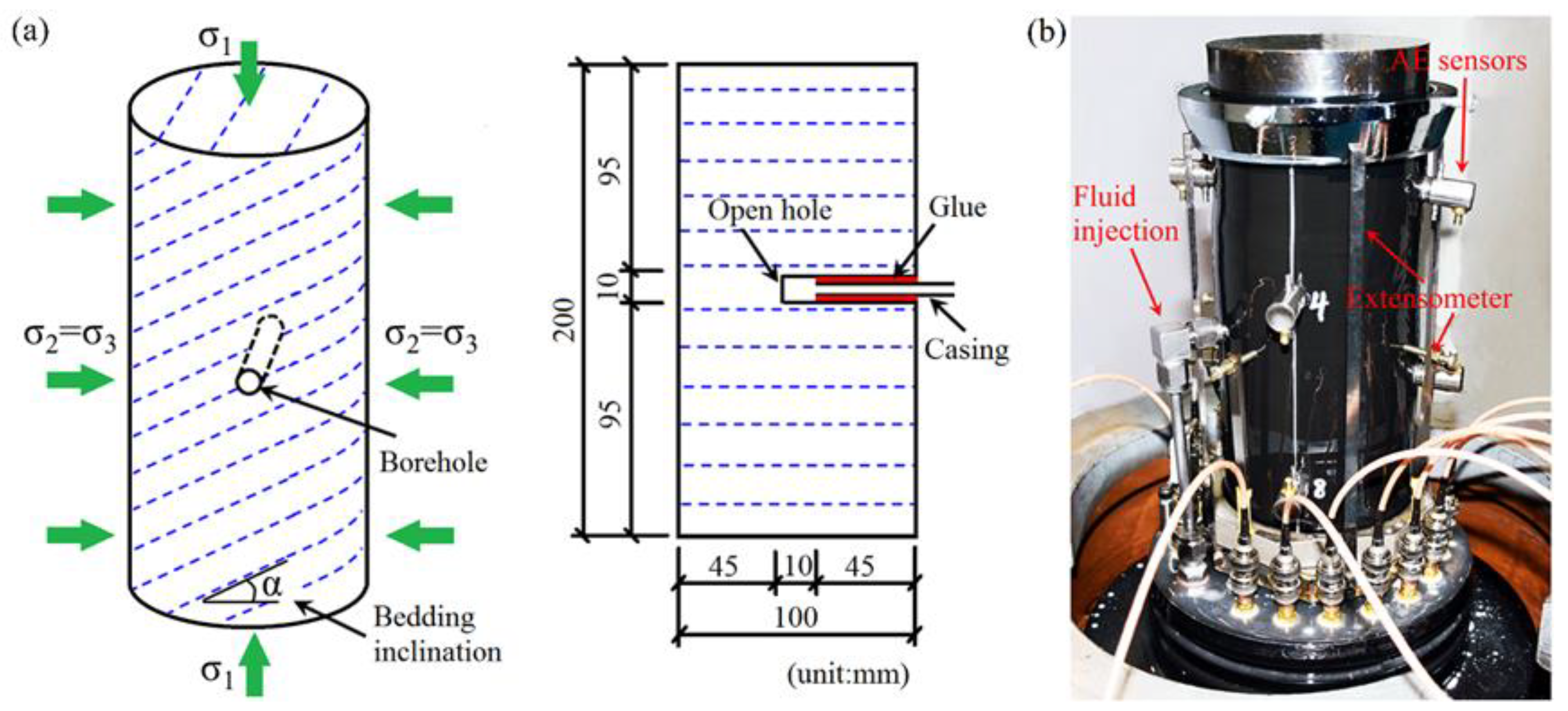
2.1. Shale Sample Preparation

The Longmaxi shale is one of the major shale gas strata in the Sichuan Basin in South China. Core samples with a diameter of 100 mm and a height of 200 mm were drilled from the outcrop near the Jiaoshiba area with different bedding angles (0°, 30°, 45°, 60°, 75°, 90°). A horizontal borehole with a diameter of 10 mm and a length of 50 mm was drilled along the bedding strike in the shale core, as shown in Figure 1a. Then, a steel tube was inserted into the horizontal borehole to simulate the casing. An open hole with a length of 10 mm was left to initiate a hydraulic fracture. The interspace between the borehole and steel tube was filled with resin adhesive.
The mineral composition of the tested shale sample is dominated by brittle minerals, such as quartz, feldspar, pyrite, and dolomite [20]. According to the uniaxial compression and Brazilian splitting tests, the shale sample showed significant mechanical anisotropy due to weak bedding interfaces [20]. During hydraulic fracturing, the interaction of a hydraulic fracture with weak bedding interfaces is critical for hydraulic fracture propagation. Therefore, in our experiment, the hydraulic fracture initiation from a horizontal perforation and intersecting with the bedding interface at different angles was monitored using acoustic emission sensors and extensometers, as shown in Figure 1b. The acoustic emission sensors (R 100 D) have an operating frequency range of 150~400 kHz and a resonant frequency of 300 kHz. To avoid environmental acoustic noise, the sensor is covered with stainless steel. The end of the sensor has a curved surface, which can be suitably adhered to the sample surface. A PCI-2 acoustic emission detecting system developed by the Physical Acoustic Corporation is employed to monitor the hydraulic fracturing process. The peak definition time, hit definition time and hit lockout time are set as 500 μs, 1500 μs, and 2000 μs, respectively. The longitudinal wave velocity was set to 3700 m/s in the acoustic emission monitoring tests. The radial extensometer has a measurement accuracy of 0.2 μm, which could record the sample dilation during fracture initiation and opening.

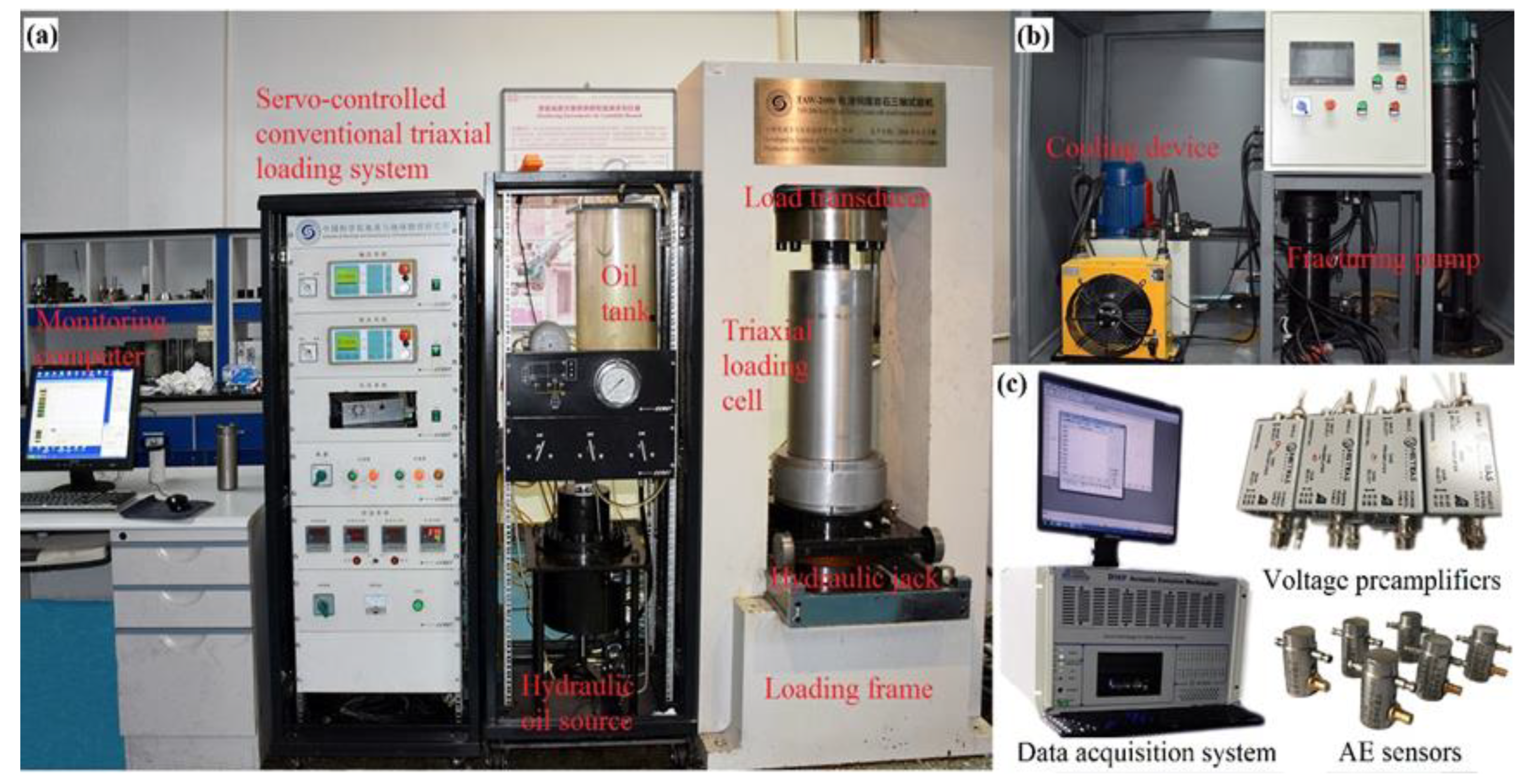
2.2. Experimental Setup

The experimental apparatus consists of a triaxial stress loading system, a hydraulic pressure pump, and an acoustic emission detecting system, as shown in Figure 2. The maximum axial loading and confining pressure were 2000 kN and 60 MPa. A hydraulic pump with a maximum injection pressure of 90 MPa was used to fracture shale samples.
Twelve groups of shale fracturing tests were conducted to investigate the effect of bedding anisotropy and stress level on hydraulic fracture propagation in shale. The detailed experimental scheme is shown in Table 1.
The procedures for shale hydraulic fracturing tests are as follows: (1) The shale sample is coated by a rubber tube to isolate the sample from hydraulic oil. (2) Eight acoustic emission sensors and extensometers were adhered to the shale sample surface. (3) The shale sample is placed into the triaxial loading cell, and a steel tube is used to link the casing with the base of the loading cell. (4) Axial stress and confining pressure are applied to the sample until the design value is reached. (5) Fluid is injected at a constant rate of 30 mL/min into the shale sample until the breakdown occurs. The acoustic emission monitoring and deformation measurement are conducted simultaneously. (6) The fractured samples are scanned using an industrial X-ray CT device to obtain the internal fractures. It should be noted that the triaxial loading system and CT apparatus were developed by the Institute of Geology and Geophysics, Chinese Academy of Sciences. The voltage of the X-ray source is 450 KeV, and the spatial resolution of the scanning is about 0.129 mm.

3. Results and Discussion

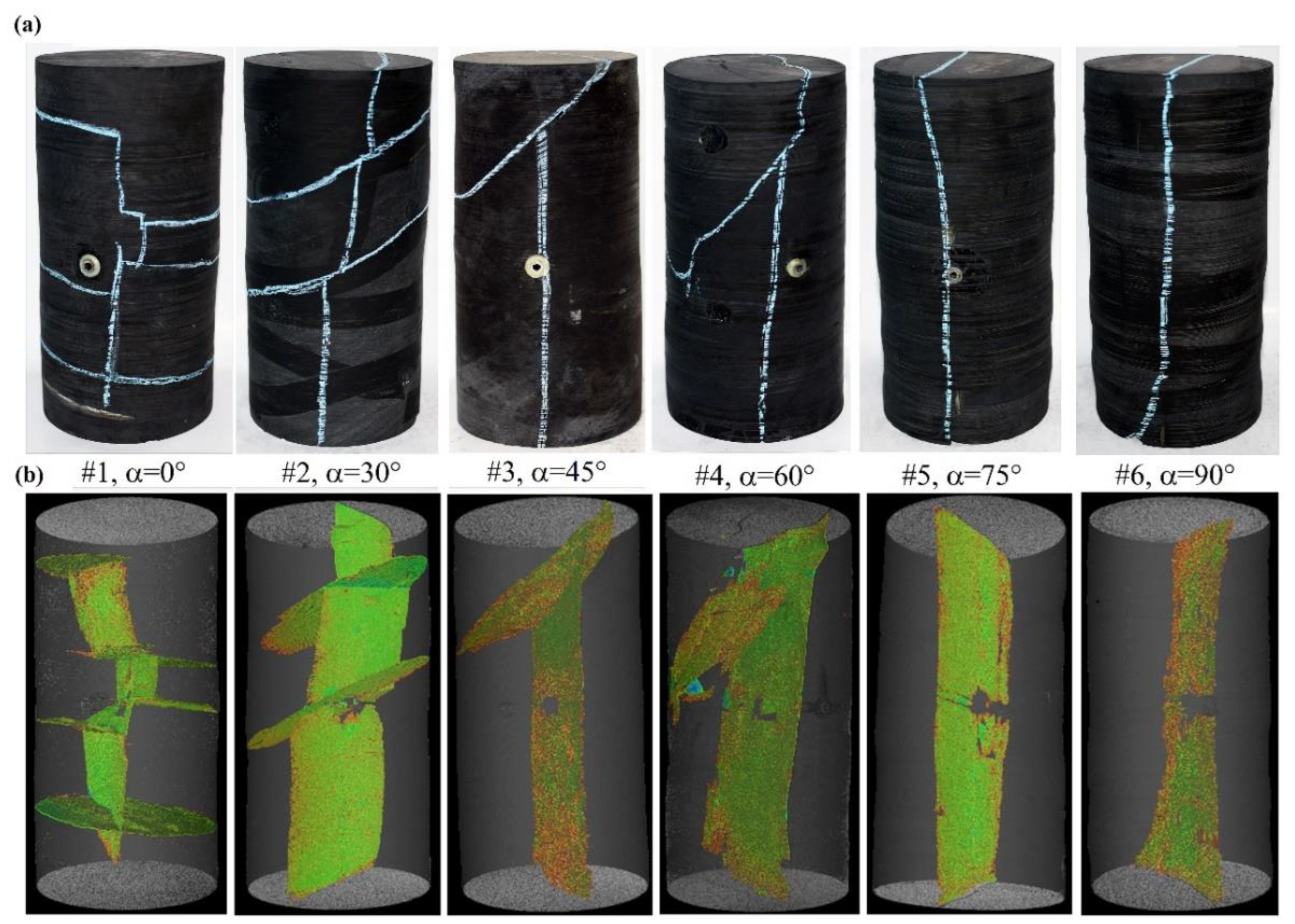
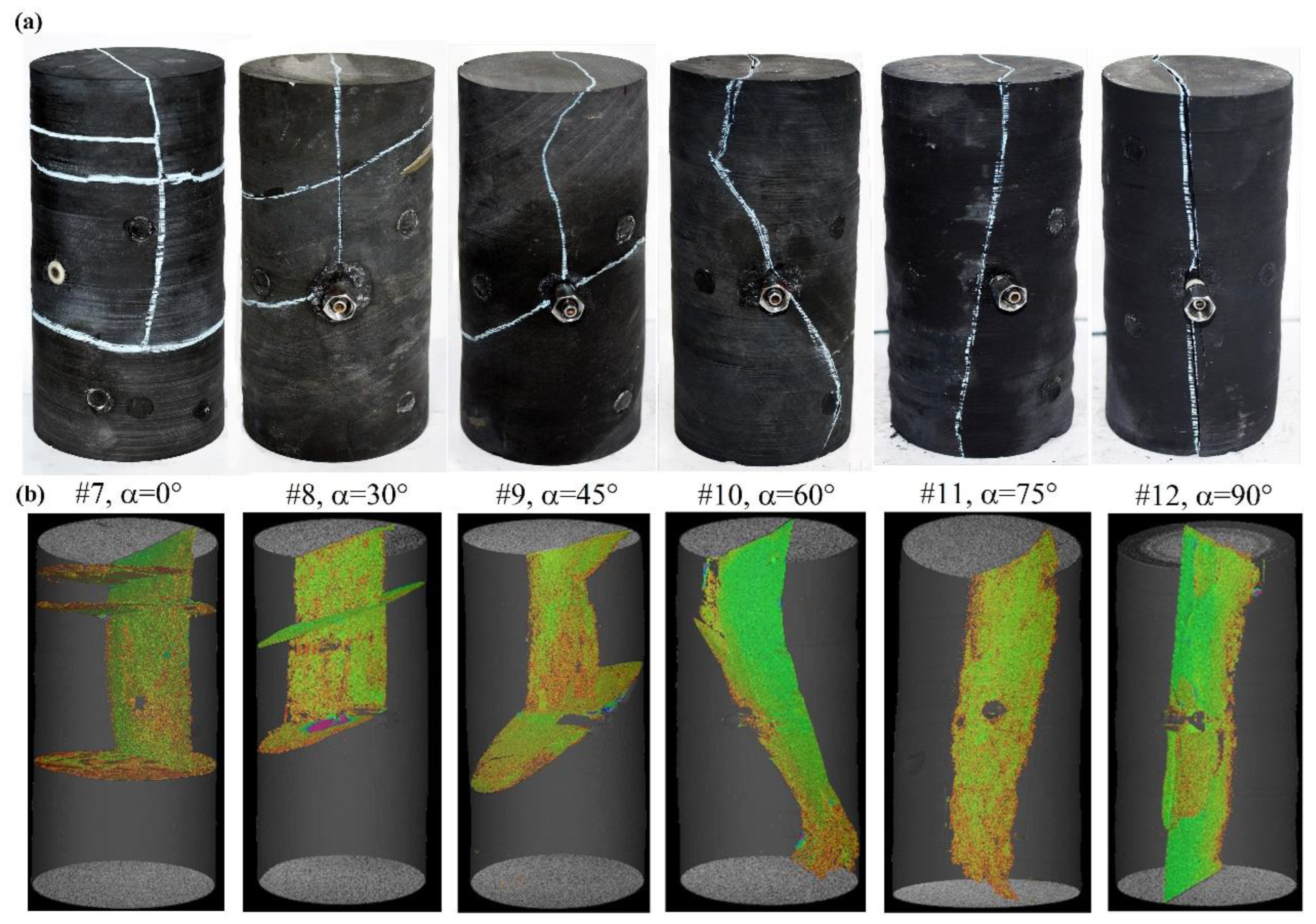
3.1. Characteristics of Hydraulic Fracture Geometry

The induced hydraulic fracture in shale samples under a lower in situ stress level is shown in Figure 3. It revealed that the bedding angles of the shale significantly affected the hydraulic fracture geometry.
For sample #1, with bedding orientated normal to the axial stress, the vertical growth of the hydraulic fracture was retarded and deflected by weak bedding interfaces. The reconstructed three-dimensional fracture based on CT images showed that the hydraulic fracture pathway was tortuous. When the bedding inclination increased to 30°, a similar deviation was observed when the hydraulic fracture crossed the weak interfaces. In this case, the fracture path became more planar compared with that of sample #1. The hydraulic fracture propagation showed analogous characteristics for samples #3 and #4, which showed a vertical fracture stopped by the bedding interface. With the further increase in bedding inclination, a planar hydraulic fracture initiated along the borehole and propagated towards the axial stress direction (samples #5 and #6).
Figure 4 presents the hydraulic fracture growth in shale samples under a higher stress level. It suggested that the stress level and bedding angle significantly influenced the geometry of the hydraulic fracture. The hydraulic fracture height of shale samples #7, #8, and #9 was smaller than that of samples #1, #2, and #3. The weak bedding interface stopped the downward growth of the hydraulic fracture. When the bedding inclination exceeded 60°, the hydraulic fracture mainly propagated along the bedding orientation. The detailed spatial fracture geometry is shown in Figure 4b. The vertical growth of the induced fracture was mainly on one side of the shale sample when the bedding inclination was smaller than 60°. Fisher and Warpinski [33] reported a field scale study of hydraulic fracture vertical growth, and the results demonstrated that weak interfaces confined the hydraulic fracture height, and the fracture vertical extension was asymmetric. This observed fracture behavior is consistent with our experimental results, especially for shale samples with small bedding inclinations. The above analysis indicated that the increased stress level was adverse for the hydraulic fracture vertical propagation. Once the weak bedding interface obstructed the hydraulic fracture, it favored the growth of one wing and led to nonsymmetric growth of the hydraulic fracture.

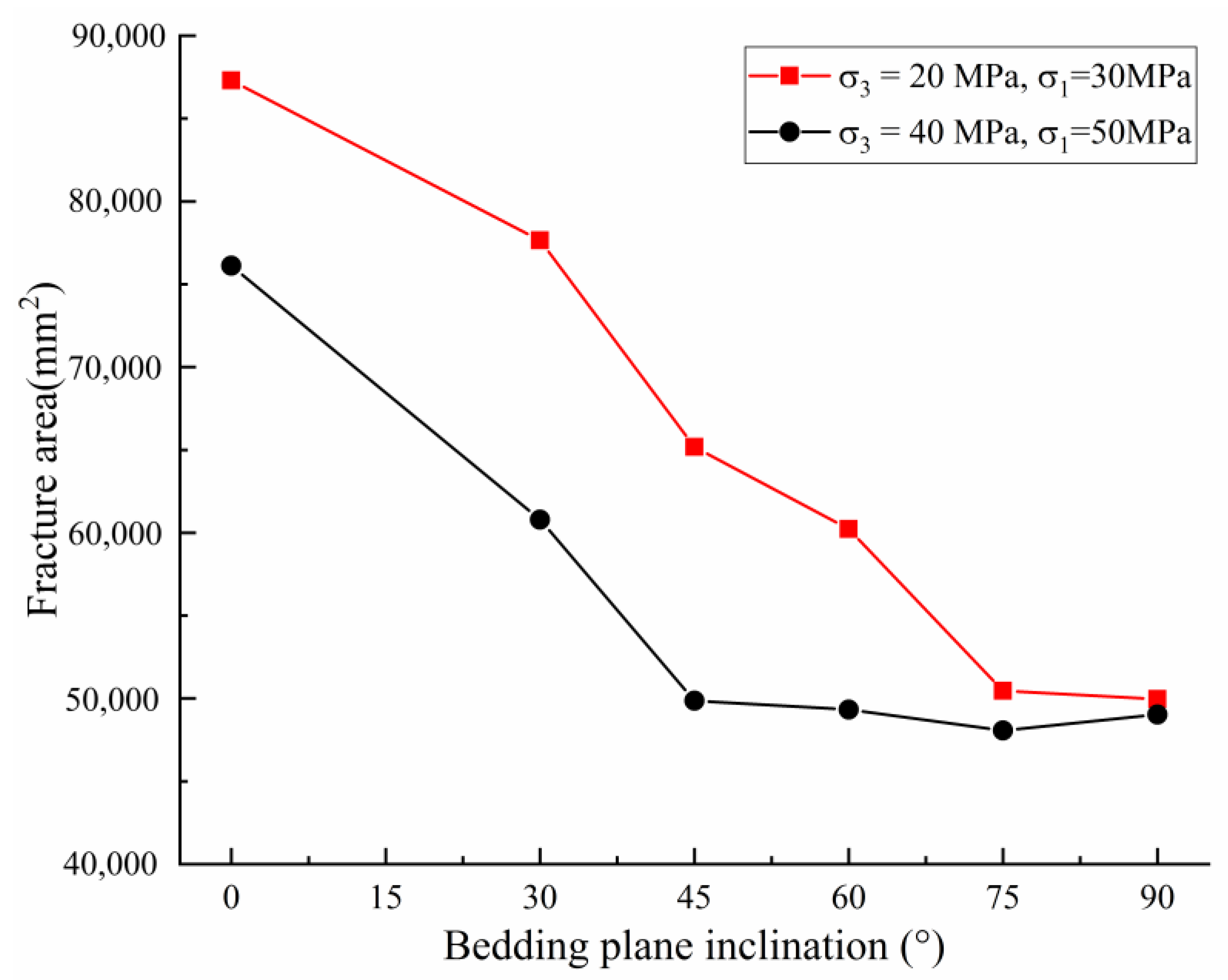
3.2. Quantitatively Analysis of Hydraulic Fracture Networks

The fracture area of tested shale samples was calculated based on CT scanning and reconstruction to evaluate the effect of the stress level and bedding inclination on hydraulic fracture geometry, as shown in Figure 5. It illustrated that bedding orientations and external stress conditions significantly influenced the hydraulic fracture area.
For shale fracturing under a higher stress level and a smaller bedding inclination, the induced fracture area was significantly smaller than that created under a lower stress level. In particular, the shale sample with a bedding inclination of 0° had the largest fracture area. With the increase in bedding inclination, the fracture area gradually decreased. The activation of weak bedding interfaces by vertical hydraulic fracture is critical for the increase in stimulated reservoir area. Zheng et al. [34] investigated the effect of confining pressure on hydraulic fracture branching in tight sandstone, and the results showed that the branch fracture volume under a lower confining pressure and injection rate was more prominent than that produced in samples under a high confining pressure. They also pointed out that increasing the injection rate could counteract the restraint of high confining pressure on hydraulic fracture branching. From this perspective, the fracturing of deep-buried shale reservoirs should increase the fluid injection rate to alleviate the restraint of a high-stress level on hydraulic fracture growth.
Understanding the relationship between hydraulic fracture spatial configuration, in situ stress level, and bedding inclination is critical to shale fracturing. A quantitative method is employed to characterize the hydraulic fracture network index [20]. Three dominating factors, including fracture density, spatial fracture homogeneity, and branching degree, are adopted to obtain a normalized parameter reflecting the hydraulic fracture network index based on the analytic hierarchy process method. The production rate is generally believed to have a positive relationship with the induced hydraulic fracture number [35]. Also, creating a hydraulic fracture network is more favorable than planar fractures. Therefore, the weight value of the fracture density, spatial homogeneity, and branching degree are 0.58, 0.31, and 0.11, respectively [20].
Specifically, the fracture density is the normalized ratio of the hydraulic fracture area to the sample volume defined as
I f = D D m i n D m a x D m i n
where   D = A / V measures the fracture area per unit volume, A and V denote the fracture area and the sample volume, respectively. The spatial fracture homogeneity measures the hydraulic fracture growth in different orientations. As shown in Figure 6a, the hydraulic fracture networks are divided into multiple small fractures, θ i measures the intersection angle between the normal vector of a given fracture and the z-axis, and β i measures the intersection angle between the projected normal vector on the x-y plane and the x-axis. The direction matrix of a hydraulic fracture network is defined as
γ = sin θ i cos β i     sin θ i sin β i     cos θ i T
The hydraulic fracture orientation with respect to the three axes is calculated as
λ 1 = i = 1 n S i S sin 2 θ i cos 2 β i ,   λ 2 = i = 1 n S i S sin 2 θ i sin 2 β i ,   λ 3 = i = 1 n S i S cos 2 θ i ,  
where   λ 1 + λ 2 + λ 3 = 1 . Then, the spatial fracture homogeneity can be written as
H f = 1 λ m a x 1 3 2 + 2 λ m i d 1 3 2 + 3 λ m i n 1 3 2
The branching degree measures the intersection of hydraulic fractures, which is defined as
  B f = b b m i n b m a x b m i n
where b = c i / l , c i is the intersection length of fractures and l is the height of the sample.
The hydraulic fracture network index is written as
I H F N = 0.58 I f + 0.31 H f + 0.11 B f
Figure 6b plots the hydraulic fracture network index curves under different stress levels and bedding inclinations. It revealed that the increase in stress level caused a reduction in the fracture network index. Shale gas exploitation in deep reservoirs always faced problems of insufficient fracturing, low fracture conductivity, and rapid decline in production [2]. The hydraulic fracture geometry for a shale gas reservoir with a larger buried depth is quite different from that of a smaller depth [2]. We found that the obstructed vertical growth of hydraulic fractures under a higher stress level could decrease the fracture complexity. Moreover, the increasing bedding inclination was also disadvantageous to the creation of fracture networks. The curves of the hydraulic fracture network index under two different stress conditions showed similar behaviors of a linear decrease with an increase in bedding inclination.

3.3. Fluid Pressure Curves and Acoustic Emission Activity

Integration fluid injection pressure curves and acoustic emission activities have proven useful in revealing the hydraulic fracture initiation and propagation [7,16]. To investigate the effect of bedding inclination on hydraulic fracturing of shale, we divided the fluid pressure curves into three stages: (1) micro-crack generation, denoted by a slight increase in acoustic emission energy; (2) hydraulic fracture initiation, where fluid pressure decay is accompanied by rising acoustic emission energy; and (3) unstable fracture propagation and breakdown, where the fluid pressure instantly decreases to the level of the confining pressure.
Figure 7 presents the fluid pressure curves and acoustic emission activities during hydraulic fracturing of shale samples with different bedding inclinations. For sample #7, minor acoustic emission energy emerged when the injection pressure reached 55 MPa, suggesting the onset of micro-cracks. Then, the hydraulic fracture was initiated when the fluid pressure linearly increased to 79.3 MPa, accompanied by a significant increase in the acoustic emission energy (Figure 7a). Afterward, the pressure curve continued to increase until unstable fracture propagation and physical breakdown occurred at 81.5 MPa, indicated by an instantaneous decay of fluid pressure and peak acoustic emission activity. The hydraulic fracturing process of sample #7 showed progressive failure characteristics, and the time from micro-crack generation to physical breakdown was about 61 s.
The feature of the fluid pressure curve changed when the bedding inclination increased to 30° (Figure 7b). An initial increase in the acoustic emission energy was recorded when the injection pressure exceeded 62.5 MPa, suggesting the onset of micro-cracks. The pressure curve gradually deviated from linear growth with a reduced gradient. When the injection pressure increased to 74.6 MPa, the hydraulic fracture propagated instantly, resulting in physical breakdown and a surge in acoustic emission energy. After that, the pressure curve decreased and balanced with the confining pressure. Compared with sample #7, the process from subcritical crack initiation to sample breakdown was about 59 s.
The further increase in bedding inclination would shorten the hydraulic fracture development process. For shale sample #9, micro-cracks began to form under a fluid pressure of 59.7 MPa. Then, the pressure curve grew until unstable fracture propagation and breakdown occurred at 68.4 MPa. The total time for hydraulic fracture creation was about 32 s, significantly faster than for samples #7 and #8. The fracturing curves and acoustic emission activities of samples #10, #11, and #12 were relatively simple, without an apparent energy release in the micro-crack generation stage. Once the hydraulic fracture was initiated, it rapidly propagated through the sample, leading to a physical breakdown. The hydraulic fracture propagating along the inherent bedding interface that orientated towards the axial stress was significantly faster. Gehne et al. [7] pointed out that the hydraulic fracture crossing many bedding interfaces presented a longer fracturing process and generated a more complex acoustic emission response than the bedding splitting mode, consistent with our observations. The above analysis suggested that the angle of structural planes significantly influenced the hydraulic fracture development in shale. Bedding fractures, shear fractures, tension fractures, and faults with varied inclinations are typically developed in the southeastern areas of the Sichuan Basin [4]. Practical fracturing engineering should consider structural interfaces’ effect on the hydraulic fracture propagation to avoid excessive fracture height growth along the steep dipping interfaces [5].

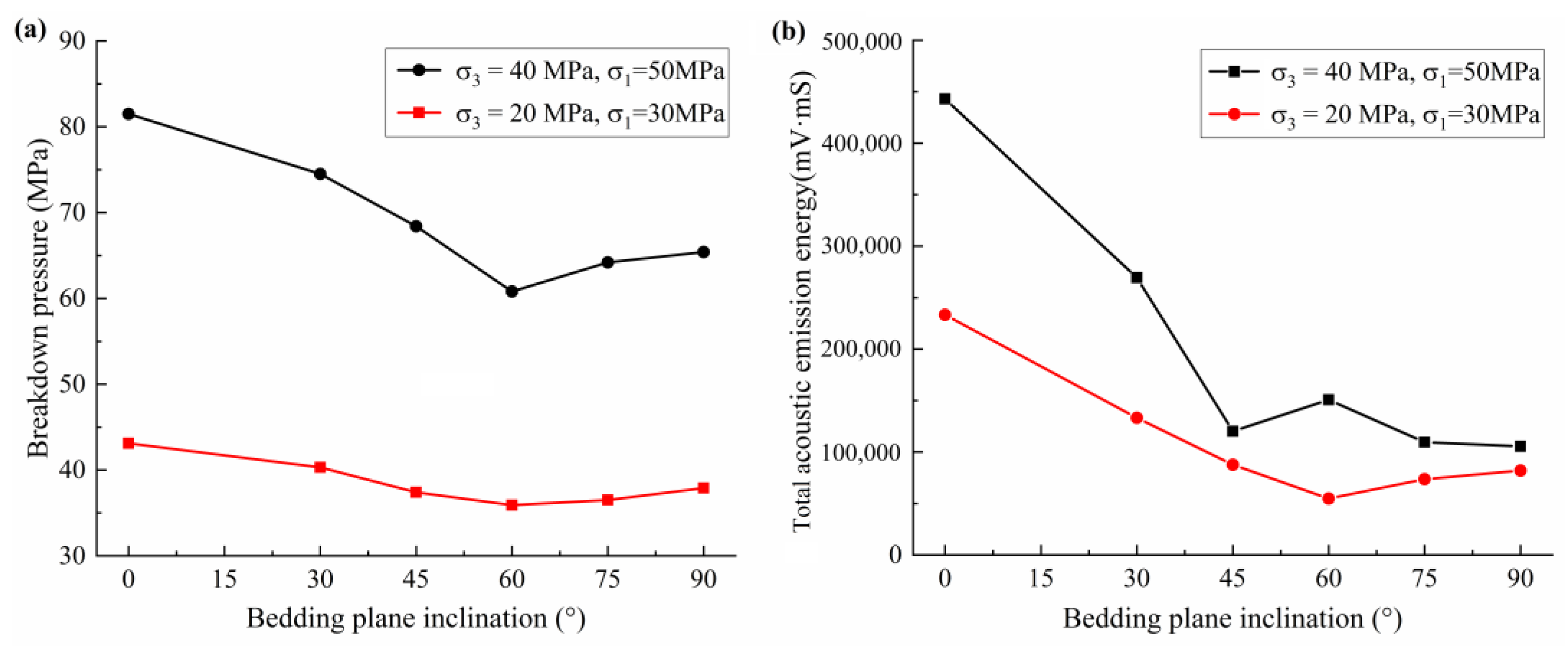
3.4. Comparison of Breakdown Pressure and Acoustic Emission Energy

The breakdown pressure is one of the critical parameters for shale fracturing design, such as the determination of the minimum horizontal principal stress and the maximum injection pressure [36,37]. Figure 8a presents the breakdown pressure of shale samples under different in situ stress conditions and bedding inclinations. It was observed that the breakdown pressure curve showed a first decrease and then an increase with increasing bedding inclination. In particular, the shale sample with a bedding inclination of 0° and 60° had the maximum and the minimum breakdown pressure, respectively. The increasing stress level significantly increased the breakdown pressure. The breakdown pressure of samples #7~#12 increased by 69%~89% compared with samples #1~#6. With the increase in stress level, the circumferential stress around the borehole wall typically increased, resulting in the elevation of fracture initiation and breakdown pressure [23,34,38].
Figure 8b shows the total acoustic emission energy curves under different in situ stress conditions and bedding inclinations. The hydraulic fracturing of the shale sample with bedding orientated to the axial stress released the maximum acoustic emission energy. The energy curves significantly decreased when the bedding inclination increased from 0° to 45°. With a further increase in bedding inclination, the energy curves remained low. Moreover, the acoustic emission energy changes were essentially consistent with the hydraulic fracture area, suggesting that the total acoustic emission energy could be used as a proxy for evaluating hydraulic fracture creation.

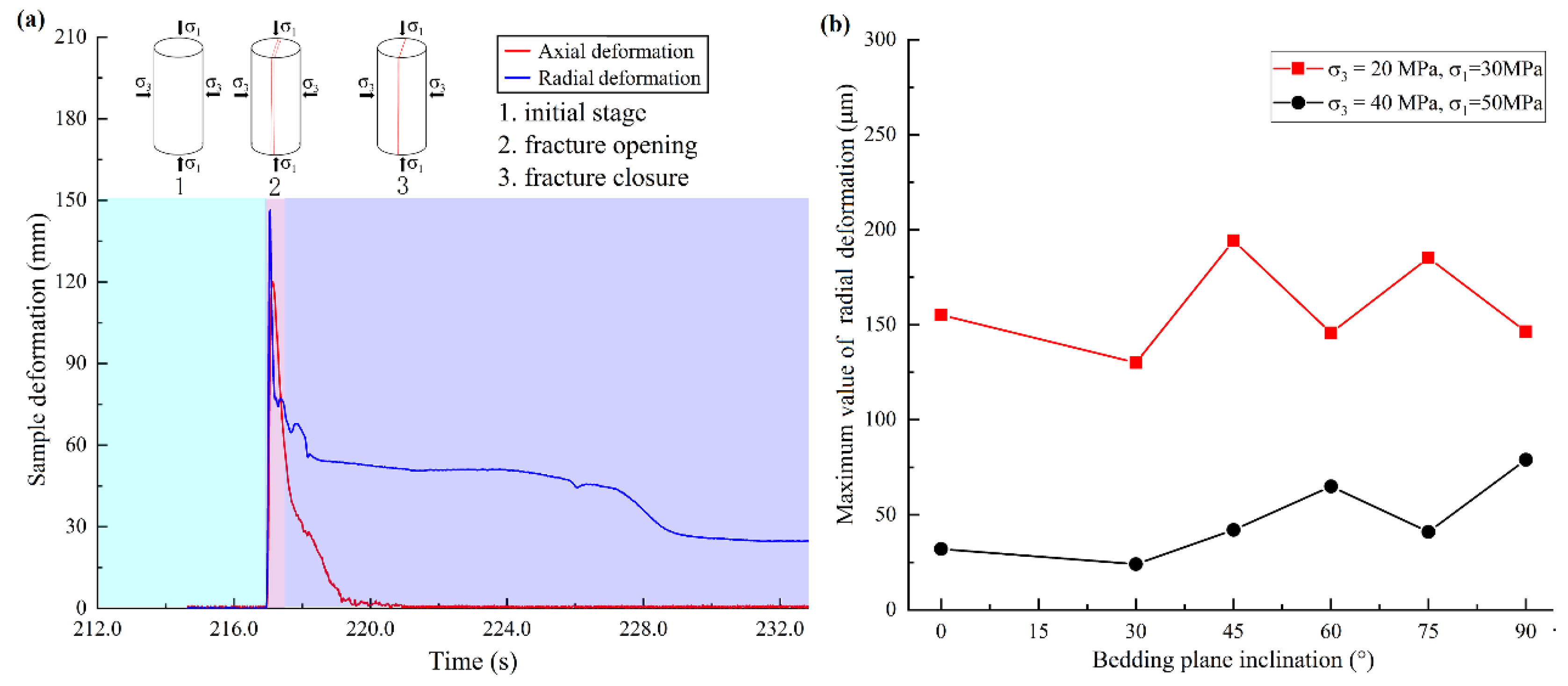
3.5. Analysis of Sample Deformation during Hydraulic Fracturing

The sample deformation during the fracturing process was analyzed to reveal the influence of the stress level on shale hydraulic fracturing. The radial deformation could illustrate the hydraulic fracture initiation, propagation, and closure process [38]. As shown in Figure 9a, the initiation of a hydraulic fracture would cause a rapid increase in radial deformation. When the induced fracture propagated and penetrated the shale sample, the fluid pressure significantly decreased and balanced with the confining pressure, leading to a reduction in the fracture width. Therefore, the maximum value of radial deformation could reflect a hydraulic fracture opening extent.
Figure 9b presents the curves of the maximum radial deformation of shale samples under different stress conditions and bedding inclinations. The results suggested that the radial deformation ranged from 130 to 194 μm under a confining pressure of 20 MPa. However, when the confining pressure increased to 40 MPa, the radial deformation significantly decreased to 24~79 μm. Zheng et al. [34] conducted hydraulic fracturing tests using in situ micro X-ray devices, and the results also suggested that the average fracture aperture decreased with increasing confining pressure. A decreased fracture opening width would increase the fluid flow resistance, resulting in increased fracturing treatment pressure [36]. The reduction of the fracture opening width would add difficulty to the proppant injection and migration [39], which could lead to low fracture conductivity and a rapid decline in productivity [2]. Measures could be taken to improve the power rate of the fracturing vehicles since the fracture width and height depend closely on the fluid injection rate [2,35]. Additionally, small-sized proppants might be selected in the fracturing operations of deep shale gas reservoirs to alleviate the problems of the reduced fracture opening width under higher stress levels [3].
We have merely investigated the effect of the stress level and bedding angle on hydraulic fracture geometry, breakdown pressure curves, and acoustic emission activities. Shale hydraulic fracturing is a complex process, and the understanding of hydraulic fracture vertical propagation and the activation mechanism of natural fractures still needs to be analyzed. Future work should focus on the evolution process of a field-scale hydraulic fracture network by conducting numerical simulations.

4. Conclusions

The creation of a hydraulic fracture network is vital for the exploitation of deep-buried shale gas and oil resources. This study investigated the hydraulic fracture initiation and growth from a horizontal borehole in shale under different in situ stress conditions and bedding inclinations. The induced fracture geometry was quantitatively evaluated using CT scans and three-dimensional reconstructions. Acoustic emission activities and sample deformation were monitored during the hydraulic fracturing process. The main conclusions are summarized below.
(1)
The increase in the in situ stress level and bedding inclination significantly decreased the hydraulic fracture area and fracture network index. The hydraulic fracture area under a higher stress level (σ1 = 50 MPa, σ3 = 40 MPa) was about 13%~23% smaller than that created under the lower stress level (σ1 = 30 MPa, σ3 = 20 MPa) when the bedding angle was smaller than 60°. Smaller stress levels (σ1 = 30MPa, σ3 = 20 MPa) and bedding inclinations (α = 0°, 30°) were favorable for creating complex fractures.
(2)
The bedding orientation significantly influenced the hydraulic fracture initiation and propagation process. For the shale sample with bedding planes normal to the maximum principal stress (σ1), the time from micro-crack generation to physical breakdown was about 61 s. When the bedding orientation changed from the horizontal to the vertical position, the fracture process was comparatively accelerated. The increasing stress level significantly increased the breakdown pressure. In particular, the fracturing of shale samples with bedding angles of 0° and 30° required higher fluid pressure and released more energy than samples with larger bedding inclinations.
(3)
The maximum radial deformation of the shale sample decreased by about 46%~81% when the confining pressure increased from 20 MPa to 40 MPa, suggesting the reduction of the hydraulic fracture opening extent under a higher in situ stress level.

Author Contributions

P.G. and X.L. conceived and designed the experiments; P.G. conducted the hydraulic fracturing tests, processed the experimental data, and wrote this paper; S.L. and T.M. revised the manuscript. All authors have read and agreed to the published version of the manuscript.

Funding

This work was supported by the National Natural Science Foundation of China (Grant No.42090023), National Key R&D Program of China (Grant No.2020YFA0710504).

Data Availability Statement

Data will be made available on request.

Conflicts of Interest

The authors declare no conflict of interest.

References

  1. Chang, C.; Tao, S.; Wang, X.; Liu, C.; Yu, W.; Miao, J. Post-frac evaluation of deep shale gas wells based on a new geology-engineering integrated workflow. Geoenergy Sci. Eng. 2023, 231, 212228. [Google Scholar] [CrossRef]
  2. Long, S.; Feng, D.; Li, F.; Du, W. Prospect analysis of the deep marine shale gas exploration and development in the Sichuan Basin, China. J. Nat. Gas Geosci. 2018, 3, 181–189. [Google Scholar] [CrossRef]
  3. Xu, S.; Liu, R.; Hao, F.; Engelder, T.; Yi, J.; Zhang, B.; Shu, Z. Complex rotation of maximum horizontal stress in the Wufeng-Longmaxi Shale on the eastern margin of the Sichuan Basin, China: Implications for predicting natural fractures. Mar. Petrol. Geol. 2019, 109, 519–529. [Google Scholar] [CrossRef]
  4. Zhang, X.; Wang, R.; Shi, W.; Hu, Q.; Xu, X.; Shu, Z.; Yang, Y.; Feng, Q. Structure- and lithofacies-controlled natural fracture developments in shale: Implications for shale gas accumulation in the Wufeng-Longmaxi Formations, Fuling Field, Sichuan Basin, China. Geoenergy Sci. Eng. 2023, 223, 211572. [Google Scholar] [CrossRef]
  5. Chen, H.; Meng, X.; Niu, F.; Tang, Y.; Yin, C.; Wu, F. Microseismic monitoring of stimulating shale gas reservoir in SW China: 2. Spatial clustering controlled by the preexisting faults and fractures. J. Geophys. Res. Solid Earth 2018, 123, 1659–1672. [Google Scholar] [CrossRef]
  6. Lin, C.; He, J.; Li, X.; Wan, X.; Zheng, B. An Experimental Investigation into the effects of anisotropy of shale on hydraulic fracture propagation. Rock Mech. Rock Eng. 2017, 50, 543–554. [Google Scholar] [CrossRef]
  7. Gehne, S.; Benson, P.M.; Koor, N.; Dobson, K.J.; Enfield, M.; Barber, A. Seisom-mechanical response of anisotropic rocks under hydraulic fracture conditions: New experimental insights. J. Geophys. Res. Solid Earth 2019, 124, 9562–9579. [Google Scholar] [CrossRef]
  8. Li, L.; Tan, J.; Wood, D.A.; Zhao, Z.; Becker, D.; Lyu, Q.; Shu, B.; Chen, H. A review of the current status of induced seismicity monitoring for hydraulic fracturing in unconventional tight oil and gas reservoirs. Fuel 2019, 242, 195–210. [Google Scholar] [CrossRef]
  9. Eaton, D.W.; van der Baan, M.; Birkelo, B.; Tary, J.B. Scaling relations and spectral characteristics of tensile microseisms: Evidence for opening/closing cracks during hydraulic fracturing. Geophys. J. Int. 2014, 196, 1844–1857. [Google Scholar] [CrossRef]
  10. Stanek, F.; Eisner, L. Seismicity Induced by Hydraulic Fracturing in Shales: A Bedding Plane Slip Model. J. Geophys. Res. Solid Earth 2017, 122, 7912–7926. [Google Scholar] [CrossRef]
  11. Wutherch, K.; Walker, K.; Aso, I.; Ajayi, B.; Cannon, T. Evaluating an engineered completion design in the Marcellus shale using microseismic monitoring. In Proceedings of the SPE Annual Technical Conference and Exhibition, San Antonio, TX, USA, 8–10 October 2012. [Google Scholar]
  12. Ma, X.; Zoback, M.D. Lithology-controlled stress variations and pad-scale faults: A case study of hydraulic fracturing in the Woodford Shale, Oklahoma. Geophysics 2017, 82, 35–44. [Google Scholar] [CrossRef]
  13. Goodfellow, S.D.; Young, R.P. A laboratory acoustic emission experiment under in situ conditions. Geophys. Res. Lett. 2014, 41, 3422–3430. [Google Scholar] [CrossRef]
  14. Triantis, D.; Pasiou, E.D.; Stavrakas, I.; Kourkoulis, S.K. Hidden Affinities between Electric and Acoustic Activities in Brittle Materials at Near-Fracture Load Levels. Rock Mech. Rock Eng. 2022, 55, 1325–1342. [Google Scholar] [CrossRef]
  15. Triantis, D.; Stavrakas, I.; Loukidis, A.; Pasiou, E.D.; Kourkoulis, S.K. Exploring the acoustic activity in brittle materials in terms of the position of the acoustic sources and the power of the acoustic signals—Part I: Founding the approach. Forces Mech. 2022, 7, 100088. [Google Scholar] [CrossRef]
  16. Triantis, D.; Stavrakas, I.; Loukidis, A.; Pasiou, E.D.; Kourkoulis, S.K. Spatio-Temporal Distribution of the Sources of Acoustic Events in Notched Fiber-Reinforced Concrete Beams under Three-Point Bending. Materials 2023, 16, 5118. [Google Scholar] [CrossRef]
  17. Triantis, D.; Loukidis, A.; Stavrakas, I.; Pasiou, E.D.; Kourkoulis, S.K. Attenuation of the Acoustic Activity in Cement Beams under Constant Bending Load Closely Approaching the Fracture Load. Foundations 2022, 2, 590–606. [Google Scholar] [CrossRef]
  18. Guo, P.; Li, X.; Li, S.; He, J.; Mao, T.; Hu, Y.; Zheng, B. Experimental Investigation of Simultaneous and Asynchronous Hydraulic Fracture Growth from Multiple Perforations in Shale Considering Stress Anisotropy. Rock Mech. Rock Eng. 2023. [Google Scholar] [CrossRef]
  19. Abe, A.; Kim, T.W.; Horne, R.N. Laboratory hydraulic stimulation experiments to investigate the interaction between newly formed and preexisting fractures. Int. J. Rock Mech. Min. Sci. 2021, 141, 104665. [Google Scholar] [CrossRef]
  20. Guo, P.; Li, X.; Li, S.; Yang, W.; Wu, Y.; Li, G. Quantitative analysis of anisotropy effect on hydrofracturing efficiency and process in shale using X-ray computed tomography and acoustic emission. Rock Mech. Rock Eng. 2021, 54, 5715–5730. [Google Scholar] [CrossRef]
  21. Guo, P.; Li, X.; Yang, W.; Mao, T. Experimental study on hydrofracture propagation through perforated wellbore in naturally fractured Guanyinqiao calcareous mudstone under true triaxial stress. J. Nat. Gas. Sci. Eng. 2022, 99, 104415. [Google Scholar] [CrossRef]
  22. Wang, J.; Xie, H.; Li, C. Anisotropic failure behaviour and breakdown pressure interpretation of hydraulic fracturing experiments on shale. Int. J. Rock. Mech. Min. Sci. 2021, 142, 104478. [Google Scholar] [CrossRef]
  23. Zhao, H.; Liang, B.; Sun, W.; Hu, Z.; Ma, Y.; Liu, Q. Effect of hydrostatic pressure on hydraulic fracturing properties of shale using X-ray computed tomography and acoustic emission. J. Petrol. Sci. Eng. 2022, 215, 110725. [Google Scholar] [CrossRef]
  24. Wang, Y.; Yan, M.Q.; Song, W.B. The effect of cyclic stress amplitude on macro-meso failure of rock under triaxial confining pressure unloading. axial loads. Fatigue Fract. Eng. Mater. Struct. 2023, 47, 3008–3025. [Google Scholar]
  25. Wang, Y.; Cao, Z.; Li, P.; Yi, X. On the fracture and energy characteristics of granite containing circular cavity under variable frequency-amplitude fatigue loads. Theor. Appl. Fract. Mech. 2023, 125, 103872. [Google Scholar] [CrossRef]
  26. Heng, S.; Liu, X.; Li, X.; Zhang, X.; Yang, C. Experimental and numerical study on the non-planar propagation of hydraulic fractures in shale. J. Petrol. Sci. Eng. 2019, 179, 410–426. [Google Scholar] [CrossRef]
  27. Zheng, H.; Pu, C.; Sun, C. Study on the interaction between hydraulic fracture and natural fracture based on extended finite element method. Eng. Fract. Mech. 2020, 230, 106981. [Google Scholar] [CrossRef]
  28. Fisher, M.K.; Wright, C.A.; Davidson, B.M.; Goodwin, A.K.; Fielder, E.O.; Buckler, W.S.; Steinsberger, N.P. Integrating fracture mapping technologies to optimize stimulations in the Barnett shale. In Proceedings of the SPE Annual Technical Conference and Exhibition, San Antonio, TX, USA, 29 September–2 October 2002. [Google Scholar]
  29. Mayerhofer, M.J.; Lolon, E.P.; Warpinski, N.R.; Cipolla, C.L.; Walser, D.; Rightmire, C.M. What is stimulated reservoir volume? SPE Prod. Oper. 2010, 25, 89–98. [Google Scholar] [CrossRef]
  30. Warpinski, N.R.; Mayerhofer, M.J.; Vincent, M.C.; Cipolla, C.L.; Lolon, E.P. Stimulating unconventional reservoirs: Maximizing network growth while optimizing fracture conductivity. J. Can. Petrol. Technol. 2009, 48, 39–51. [Google Scholar] [CrossRef]
  31. Tan, P.; Jin, Y.; Han, K.; Hou, B.; Chen, M.; Guo, X.; Gao, J. Analysis of hydraulic fracture initiation and vertical propagation behavior in laminated shale formation. Fuel 2017, 206, 482–493. [Google Scholar] [CrossRef]
  32. Zhang, R.; Hou, B.; Han, H.; Fan, M.; Chen, M. Experimental investigation on fracture morphology in laminated shale formation by hydraulic fracturing. J. Petrol. Sci. Eng. 2019, 177, 442–451. [Google Scholar] [CrossRef]
  33. Fisher, K.; Warpinski, N. Hydraulic-Fracture-Height Growth: Real Data. SPE Prod. Oper. 2012, 27, 8–19. [Google Scholar] [CrossRef]
  34. Zheng, S.; Lin, M.; Jiang, W.; Qiu, X.; Chen, Z. New method of in situ high-resolution experiments and analysis of fracture networks formed by hydraulic fracturing. J. Petrol. Sci. Eng. 2022, 217, 110849. [Google Scholar] [CrossRef]
  35. Fisher, M.K.; Heinze, J.R.; Harris, C.D.; Davidson, B.M.; Wright, C.A.; Dunn, K.P. Optimizing horizontal completion techniques in the Barnett shale using microseismic fracture mapping. In Proceedings of the SPE Annual Technical Conference and Exhibition, Houston, TX, USA, 26–29 September 2004. [Google Scholar]
  36. Yew, C.H.; Weng, X. Mechanics of Hydraulic Fracturing, 2nd ed.; Gulf Professional Publishing: Houston, TX, USA, 2015. [Google Scholar]
  37. Hossain, M.M.; Rahman, M.K.; Rahman, S.S. Hydraulic fracture initiation and propagation: Roles of wellbore trajectory, perforation and stress regimes. J. Petrol. Sci. Eng. 2000, 27, 129–149. [Google Scholar] [CrossRef]
  38. He, J.; Lin, C.; Li, X.; Zhang, Y.; Chen, Y. Initiation, propagation, closure and morphology of hydraulic fractures in sandstones cores. Fuel 2017, 208, 65–70. [Google Scholar] [CrossRef]
  39. Aslannezhad, M.; Kalantariasl, A.; You, Z.; Iglauer, S.; Keshavarz, A. Micro-proppant placement in hydraulic and natural fracture stimulation in unconventional reservoirs: A review. Energy Rep. 2021, 7, 8997–9022. [Google Scholar] [CrossRef]
Figure 1. (a) Schematic diagram of hydraulic fracturing through a horizontal borehole, (b) real photo of tested shale sample.
Energies 16 07270 g001
Figure 2. Photos of the triaxial hydraulic fracturing system. (a) Schematic diagram of triaxial loading system, (b) hydraulic fracturing pump, (c) acoustic emission monitoring system.
Energies 16 07270 g002
Figure 3. Hydraulic fracture propagation in shale core samples under a lower stress level. (a) Fracture pathway observed on sample surface, (b) spatial fracture geometry reconstructed based on CT images.
Energies 16 07270 g003
Figure 4. Hydraulic fracture propagation in shale core samples under a higher stress level. (a) Fracture pathway observed on sample surface, (b) spatial fracture geometry reconstructed based on CT images.
Energies 16 07270 g004
Figure 5. Hydraulic fracture area under different bedding inclinations and stress levels.
Energies 16 07270 g005
Figure 6. (a) Geometric parameters of hydraulic fractures, (b) Hydraulic fracture network index under different bedding inclinations and stress levels.
Energies 16 07270 g006
Figure 7. Fluid injection pressure curves and acoustic emission energy evolution for shale samples with different bedding inclinations, (a) sample #7, α = 0°, (b) sample #8, α = 30°, (c) sample #9, α = 45°, (d) sample #10, α = 60°, (e) sample #11, α = 75°, (f) sample #12, α = 90°.
Energies 16 07270 g007
Figure 8. (a) Curves of breakdown pressure of shale samples under different in situ stress conditions and bedding inclinations, (b) curves of acoustic emission energy of shale samples under different in situ stress conditions and bedding inclinations.
Energies 16 07270 g008
Figure 9. (a) Schematic diagram of different stages of hydraulic fracturing indicated by different background color, (b) maximum value of radial deformation for shale samples under different bedding inclinations and stress levels.
Energies 16 07270 g009
Table 1. Experimental scheme of triaxial hydraulic fracturing tests of shale samples.
Sample NumberBedding Inclination
(°)
Confining Pressure
(MPa)
Axial Stress
(MPa)
Stress Difference
(MPa)
Injection Rate
(mL/min)
Fluid Viscosity
(mPa·s)
#10203010301
#230203010301
#345203010301
#460203010301
#575203010301
#690203010301
#70405010301
#830405010301
#945405010301
#1060405010301
#1175405010301
#1290405010301
Shale samples #1~#6 were subjected to a lower stress level, and samples #7~#12 were subjected to a higher one. The hydraulic fracture geometrical parameters, fluid injection pressure curves, acoustic emission activities, and sample radial deformation of shale samples under different conditions were comparatively analyzed.
Disclaimer/Publisher’s Note: The statements, opinions and data contained in all publications are solely those of the individual author(s) and contributor(s) and not of MDPI and/or the editor(s). MDPI and/or the editor(s) disclaim responsibility for any injury to people or property resulting from any ideas, methods, instructions or products referred to in the content.

