

AC-DC-DC Converter for Small Power Energy Storage Systems
by
 , and
, and
Szymon Piasecki
1, 
Serafin Bachman
1,
Jarosław Zaleski
2,
Marek Jasinski
1,* and
Marek Turzyński
3 1
Institute of Control and Industrial Electronics, Warsaw University of Technology, Koszykowa 75, 00-662 Warsaw, Poland
2
Twerd Power Electronics Ltd., Aleksandrowska 28-30, 87-100 Torun, Poland
3
Faculty of Electrical and Control Engineering, Gdansk University of Technology, 80-233 Gdansk, Poland
*
Author to whom correspondence should be addressed.
Energies 2023, 16(22), 7556; https://doi.org/10.3390/en16227556
Submission received: 25 October 2023
/
Revised: 10 November 2023
/
Accepted: 11 November 2023
/
Published: 13 November 2023
(This article belongs to the Special Issue Energy Conversion and Storage in Fuel Cells, Batteries and Hybrid Electric Systems)
Abstract
:The energy transformation driven by the development of renewable energy sources has become a reality for all power grid users. Prosumer energy, primarily utilizing photovoltaic installations, is one of the fastest-growing market segments. The advancement of technology, a decrease in electrochemical energy storage prices, and changes in the legal framework governing energy billing for grid-fed power have led to a growing interest in expanding prosumer installations with energy storage modules. This article presents the authors’ concept and expected functionalities of a prosumer system equipped with energy storage based on theoretical assumptions, simulation analyses, and experimental research. Additionally, it covers the design and functionality of a hybrid converter; its experimental validation, including an analysis of operational modes; the development of a control algorithm under real conditions; and the efficiency testing of the device.
1. Introduction
The perception of electricity production and distribution has undergone a significant transformation among producers, system operators, and ordinary users in recent times. The energy transformation has indeed become a reality affecting all power grid users [1,2]. The primary driving force behind the changes occurring in the power system is the dynamic development of renewable energy sources. In just a few years, photovoltaic installations, whether with a capacity of several or several hundred kilowatts, have shifted from being an expensive technological novelty to becoming a commonplace and profitable tool for electricity generation [3]. In Poland as well, there has been a notable increase in the number of renewable energy source (RES) installations, including photovoltaic farms and small home installations with capacities of up to 15 kWp [4]. Home installations have become a permanent feature of the European residential and agricultural landscapes. With the growth of prosumer installations and ongoing technological advancements, the complexity and functionality of these installations continue to increase.
The complexity and implemented functionalities of prosumer installations are influenced by the changing legal environment and the limited capacity of distribution grids, which restricts the ability to connect new sources. The amendment of regulations regarding the accounting of energy produced and fed into the grid by prosumers, including the introduction of dynamic tariffs, aims to increase the level of the self-consumption of energy and maximize the use of available energy at its point of generation [5,6]. This is primarily due to the current condition of low-voltage distribution grids, whose expansion cannot keep up with the dynamic growth of additional renewable energy sources [7,8,9]. This issue is particularly significant in locations dominated by residential buildings. Because of the significantly varying hourly energy demand profiles within households and energy production from photovoltaic installations, it is necessary to store energy effectively at the point of its generation [10,11,12,13]. A typical daily energy profile for a household with a 10 kWp PV installation, considering energy production and consumption, recorded in Poland on an April day in 2022, is illustrated in Figure 1.
Based on the presented figure, it can be concluded that in order to effectively use the energy available from a renewable source, it must be stored. The technology best suited for widespread adoption in this field is battery energy storage. As a result, modern prosumer systems come equipped with energy storage systems. The energy storage device can be connected to the home AC grid using a DC microgrid or together with a renewable energy installation. One of the devices enabling RES installations to function with energy storage and efficiently manage available energy across various operating modes is a hybrid AC-DC-DC inverter [14,15,16,17]. Furthermore, with the implementation of proper grid-side converter control and the utilization of advanced algorithms, it becomes feasible to stabilize the voltage at the grid connection point, thereby positively influencing its characteristics and enhancing the capacity to connect subsequent devices [18,19,20,21].
2. Prosumer System Configuration
Requirements
The basic configuration of the prosumer system, equipped with a renewable energy source (PV), a hybrid inverter (HI), energy storage (ES), and energy measurement at the point of common coupling (EMPCC), is shown in Figure 2. Thanks to the use of an appropriate configuration and control algorithm, the system can operate in the following modes:
- Energy from renewable sources can be used to supply local loads;
- The ES can be charged (drawing energy from the RES or the grid);
- The energy produced by the RES can be transferred to the power grid;
- Additionally, it is possible to disconnect from the grid and supply the local loads (utilizing energy from RES installation and energy storage), operating in off-grid mode (island mode of operation);
Due to the number of possible operating modes and scenarios and the possibility of providing additional demand-side response (DSR) services to the grid operator, the complexity of such a system is high and requires the use of a supervisory control system. The energy management system (EMS) can control the system and additionally use data related to the weather forecast, the condition of the energy storage system, or the changing prices in the energy market. At present, EMS functionalities can be implemented by a hybrid inverter control algorithm, as well as the supervisory controller communicating with the system components [27,28,29,30,31].
A highly significant component of a prosumer hybrid system is energy storage. Currently, there are various types of energy storage technologies available. Energy can be stored in electrochemical batteries, in heat or cold storage systems, as kinetic energy, or in other carriers. Energy storage technologies can include other promising technologies, such as recycled batteries, supercapacitors, hybrid supercapacitors, sodium-ion batteries, flow batteries, and small hydrogen fuel cells [32,33,34,35,36,37,38,39,40]. However, due to the prevalence and commercial availability of technologies, as well as their prices, electrochemical batteries are the most popular, particularly lithium-ion and valve-regulated lead–acid (VRLA) batteries. The selection of battery technology, storage capacity, and nominal power is influenced by numerous factors [11,12,13]. Currently, the most crucial factor affecting battery selection is the price and the safety level of the system, given the early stage of market development. Consequently, the market for residential energy storage systems has been dominated by lithium iron phosphate (LFP) batteries, which can perform up to 6000 charge cycles—roughly equivalent to a potential operational lifespan of about 10 years in a household setting. Considering the energy consumption profile in a household, these batteries typically have capacities of up to 20 kWh and instantaneous power not exceeding 10 kW. Usually, due to the charging and discharging current values, these batteries operate at voltages ranging from 200 to 700 V.
A highly significant component of a prosumer hybrid system is energy storage. Currently, various types of energy storage technologies are available, including electrochemical batteries, heat or cold storage systems, kinetic energy, or other carriers. Promising technologies in the realm of energy storage include recycled batteries, supercapacitors, hybrid supercapacitors, sodium-ion batteries, flow batteries, and small hydrogen fuel cells [32,33,34,35,36,37,38,39,40]. However, due to their prevalence, commercial availability, and cost-effectiveness, electrochemical batteries are the most popular, especially lithium-ion and valve-regulated lead–acid (VRLA) batteries. The choice of battery technology, storage capacity, and nominal power is influenced by numerous factors [11,12,13].
Presently, the most critical factor impacting battery selection is the price and the safety level of the system, given the early stage of market development. Consequently, the market for residential energy storage systems has been dominated by lithium iron phosphate (LFP) batteries, capable of up to 6000 charge cycles—approximately equivalent to a potential operational lifespan of about 10 years in a household setting. Considering the energy consumption profile in a household, these batteries typically have capacities of up to 20 kWh and instantaneous power not exceeding 10 kW. Usually, these batteries operate at voltages ranging from 200 to 700 V, determined by the charging and discharging current values.
3. Hybrid Inverter
A hybrid inverter is a device that cooperates with renewable energy installations and energy storage, enabling their integration with the AC grid. Thanks to the internal DC microgrid, it is possible to connect renewable energy installations (usually PV systems) and batteries while managing energy flows. Additionally, from the grid perspective, both sources are connected at a single point. One drawback of such a solution is the need to replace the inverter if one wishes to expand an existing renewable energy installation with an energy storage system. Furthermore, the potential positive impact on the distribution grid is limited due to the inverter’s installation location. The system consists of several stages of energy conversion based on AC-DC and DC-DC converters [17,41,42,43].
- Hardware Description
The proposed concept of a hybrid inverter is depicted in Figure 3. On the grid side, the primary device is an AC-DC converter, typically employing a four-leg topology in energy storage solutions to facilitate islanding mode, allowing the system to operate “off-grid”. In island-mode operation, the converter serves as the voltage source for local loads. The frequency and RMS voltage values must be maintained in accordance with the grid code requirements. Furthermore, the device must synchronize with the grid upon returning to “on-grid” operation. The use of a four-leg topology allows for stable operation in the presence of unbalanced loads on the local load side and the control of the neutral wire current. Additionally, independent control for each phase of the input voltage enables voltage stabilization and balancing at the point of connection to the grid, which has a positive impact on the distribution grid.
On the renewable source side, unidirectional, non-isolated DC-DC converters are utilized. The number of converters depends on the number of Maximum Power Point Tracking (MPPT) systems. In this concept, a crucial component is the bidirectional DC-DC converter, responsible for voltage matching between the converter’s DC bus and the battery, as well as controlling the battery charging or discharging current. Depending on the chosen system configuration and battery voltage level, it can be a bidirectional non-isolated DC-DC converter or a galvanically isolated converter, often taking the form of a dual-active-bridge (DAB) converter [41,42].
Figure 3 illustrates the current and voltage measurements within the system, which are necessary for the control of individual components. An additional active element is a switch that allows for disconnecting the converter from the grid and switching to island operation, ensuring uninterrupted power supply to the local load through the use of an advanced control algorithm, which seamlessly transitions between on-grid and off-grid modes.
As a separate component, an energy management system is included, which can be implemented through the converter algorithm based on current and voltage measurements. However, enhancing the level of intelligent energy management in the system, such as by utilizing additional data, often requires the incorporation of an external EMS controller.
- B.
- Control Algorithm
In the provided solution, the control algorithm consists of multiple blocks, depending on the operational mode of the system. The control of the AC-DC grid converter is carried out based on measurements of the primary currents and voltages, which are used for the transformation to the rotating d-q coordinate system [21,31,43]. When operating with the power grid (in on-grid mode), the reference values for individual phase currents are determined based on the preset voltage in the DC circuit and the measured grid angle. The control system diagram for grid operation is depicted in Figure 4.
In the case of operation in the off-grid mode, the priority is to ensure the parameters of the generated voltage. The phase voltage values are the set points for the resonant regulators used for this purpose. The diagram of the control system in the case of the off-grid mode is presented in Figure 5.
The battery charging/discharging current is regulated by a bidirectional DC-DC converter. In the analyzed case, it is a system without galvanic separation. Therefore, the reference value of the battery current is determined from the measured voltages in the DC link. The scheme of the control algorithm is shown in Figure 6.
The last component of the system is the maximum power tracking system implemented by a unidirectional DC-DC converter. In the analyzed case, the MPPT algorithm applies to a photovoltaic installation. The algorithm is implemented on the basis of the measured electrical values of PV panels, taking into account the DC voltage in the converter’s intermediate circuit. The circuit diagram is shown in Figure 3.
4. Simulation Study
The simulation studies concerned the grid part of the system (AC-DC converter) due to the complexity of the analyzed system and the control algorithm used. DC-DC converters were developed as part of previous work and were integrated at the device prototype stage. In order to verify the assumptions and theoretical analyses, a simulation model of the three-level AC-DC converter with four active legs was developed in the PLECS environment and tested. The simulation model consists of a grid model with voltage asymmetry, an asymmetric load model connected deep within the grid, a converter model, and a voltage source connected directly to the converter’s intermediate DC circuit. A view of the developed simulation model is shown in Figure 7, where Figure 7a shows the converter power circuit and Figure 7b shows the implemented control structure.
In the initial phase of the simulation work, various operating modes were studied at nominal values, and open-loop regulation was employed to determine the current and voltage values in the designed converter. Based on steady-state simulations under nominal conditions, the selection of DC circuit capacitance, nominal current values for semiconductor power components, and the parameters of magnetic elements (current, inductance) was made, along with the selection of LC filter components on the grid side.
In the next step of the simulation model for the AC-DC converter, a closed-loop control structure was implemented based on voltage-oriented control with vector modulation, where reference values are provided in the rotating d-q coordinate system. During the simulation analysis, the gains of the PI current regulators in the d and q coordinates were adjusted to obtain satisfactory dynamics and the shape of the grid-side current. In the next step, the gain of the DC-link voltage PI regulator was selected. The proper operation of the closed-loop control system was verified under both static and dynamic conditions.
In the next step, the simulation study focused on analyzing the impact of the converter on the power grid and the possibility of stabilizing the grid parameters through the applied control algorithm extended with voltage stabilization functionality. The research was conducted in a system where the inverter is connected to both the grid and renewable energy sources, while loads are also connected further into the grid. The aim of the research was to analyze the improvement in grid parameters achieved by the converter’s voltage stabilization algorithm in order to maintain the operational parameters of loads using energy from renewable sources.
Figure 8 shows the operation of the converter in the static state, supplying the load connected deep in the grid from a renewable source and stabilizing the grid voltage asymmetry. Figure 8a shows the waveforms of grid currents and voltages in a situation where the converter is not operating, and the load is connected to the grid and is powered directly by the grid. Then, Figure 8b shows the situation in which the converter operates and transmits energy to the grid to power the connected load: the currents drawn from the grid by the load at the measurement point are equal to zero. Figure 8c shows a similar situation when a 30% dip occurs in one phase. The system compensates the grid voltage to the value of the set current limit, and only the difference between the converter and load currents is taken from the grid.
The following waveforms presented in Figure 9 show the dynamic state and illustrate the operation of the algorithm to stabilize grid parameters. Figure 9a shows the operation of the source, which increases the grid voltage with the converter operating. In the last part of the waveform, the grid stabilization algorithm is activated (lowering the voltage), which results in an increase in the converter currents and a reduction in the effective value of the grid voltage. Figure 9b shows the operation of the grid stabilization algorithm when a 30% voltage dip occurs in one of the phases. The operation of the stabilization algorithm is visible through the increased and asymmetric currents of the analyzed AC/DC converter.
5. Experimental Test Bench
To verify the performed analysis, an experimental model of the AC-DC-DC converter dedicated to hybrid prosumer installations was verified in laboratory research. For the purpose of verifying the functionality and operating modes of the hybrid inverter, a dedicated experimental test stand was created, a view of which is shown in Figure 10.
The stand consists of the tested 12 kW hybrid inverter, an energy storage device with a capacity of 10 kWh made with LFP technology, a renewable source model, a connection point to the power grid, and the local load (resistors). The system is connected to the actual LV grid, and for the purposes of precise measurement recording, high-class oscilloscopes, a grid analyzer, and a power analyzer were used. The conducted research was divided into two main stages: testing the functionality and operating modes of the inverter and analyzing the efficiency of the tested hybrid inverter. The parameters of the inverter are collected in Table 1.
- Functionality tests
In the initial stage of the research, the proper operation of the system in the static state was verified. The following operation modes were analyzed:
- Charging the energy storage (battery) from a renewable energy source;
- Charging the energy storage (battery) from the grid;
- Simultaneously charging the battery from the grid and a renewable energy source;
- Discharging the storage to the grid for local loads;
- Using the islanding operation mode (off-grid mode).
Figure 11 illustrates the off-grid operating mode with an asymmetrical load, which is the most challenging to implement for a hybrid system and requires a four-leg converter topology. The figure displays the current and voltage waveforms of an asymmetric load (Uabc_load, Iabc_load), as well as the battery current (Ibatt) and voltage (Ubatt) waveforms. Due to the significant imbalance in the load currents, considerable oscillation of the battery current is visible.
In the subsequent stage of the research, the operation of the inverter in the dynamic state was examined. Figure 12 displays the oscillograms recorded during the transition of the operating mode from the on-grid mode (with battery charging) to the off-grid mode supplying local loads (battery discharging). The waveforms of the battery voltage, battery current, PV string current, and voltage are depicted in Figure 12a. It can be observed that the battery current changes direction, shifting from the charging to discharging mode. Subsequently, Figure 12b illustrates the current and voltage waveforms of one of the phases on the grid side, as well as the current and voltage waveforms of one phase of the load.
During subsequent tests, the transition of the operating mode from on-grid to off-grid was observed with an asymmetrical local load. The waveform of the battery current and voltage, the string voltage of photovoltaic panels, and the voltage of one phase of the grid are presented in Figure 13a. A noticeable step change in the direction of the battery current is evident, shifting from the charging to discharging mode with a high imbalance in the load currents, resulting in a significant current ripple in the battery current. In turn, Figure 13b illustrates the local load phase current waveforms and the voltage waveform of one of the load phases.
- B.
- Efficiency tests
As part of the hybrid inverter analysis, the system’s efficiency was also measured, considering the entire voltage conversion path. The results were recorded in the static state using a Yokogawa WT1800 power analyzer. The setup of the measurement stand is illustrated in Figure 14. The inverter’s efficiency was assessed during the conversion of energy from a renewable source (Figure 14a) and during the conversion of energy from a battery storage (Figure 14b).
The recorded efficiency characteristics are presented in Figure 15. With two energy conversion stages (AC-DC and DC-DC converters), the inverter achieves an efficiency of 97.5% at rated values (for two-stage energy conversion from PV panels to the AC grid, bypassing the batteries). In the process of converting energy from the battery, the efficiency is lower (at the level of 95.5%), which results from the applied topology of the DC-DC bidirectional converter and a different voltage range in which the battery operates (the battery’s nominal rated voltage is 200 V).
6. Discussion and Conclusions
This article introduces the concept of a hybrid inverter, considering the potential operating modes of the device. It outlines the individual components of the system, along with the employed control algorithms. The positive influence of the converter with a dedicated regulation algorithm on the power grid was verified through numerous simulation tests. Subsequently, using a dedicated laboratory setup, the system’s performance was validated through a series of experimental tests. The results obtained confirm the anticipated functionalities and parameters of the hybrid inverter.
Throughout the execution of this study, a complete research cycle, commonly employed in the technical sciences, was undertaken. The authors’ contribution lies in presenting the solution concept along with the utilized control algorithms. The functionalities and attributes of the proposed solution have been substantiated through various analytical studies, the development of a dedicated simulation model, and simulation tests. To validate the implementation potential of the presented concept, experimental tests were conducted, affirming the device’s operation under conditions resembling real-world scenarios.
As part of the presented work, the authors have proposed and substantiated a thesis regarding the positive impact of a prosumer converter with an energy storage device on the distribution grid, utilizing advanced system control methods. An area requiring further exploration is off-grid operation in the presence of significant imbalances in the load currents. The recorded battery current exhibits notable oscillations with a 100 Hz component. To optimize battery operation parameters and enhance its service life, efforts are needed to minimize this component when operating on separate loads. In the process of converting energy from the battery, the system efficiency is less than 2% compared to the grid supply. Future work will concentrate on assessing the impact of the DAB converter in various topologies on the system’s operation.
Author Contributions
Conceptualization, S.P. and M.J.; methodology, S.P.; software and validation, J.Z.; investigation and resources, J.Z. and S.B.; writing—original draft preparation, S.P.; writing—review and editing, M.J., S.B. and M.T.; project administration and funding acquisition, M.J. All authors have read and agreed to the published version of the manuscript.
Funding
This research was partly financed under grant funding for research in the discipline of Automatics, Electronics and Electrical Engineering at the Faculty of Electrical Engineering of the Warsaw University of Technology and partly by the “Poland-Taiwan cooperation POLTAJ VII 7th competition Path 1” project, co-financed by the National Center for Research and Development.
Data Availability Statement
Data are contained within the article.
Conflicts of Interest
The authors declare no conflict of interest.
References
- Zinaman, O.R. An Overview of Power System Transformation—The Impacts of New Technologies and Innovations; Sao Paulo State Department of Infrastructure and Environment: Sao Paulo, Brazil, 2019. [Google Scholar]
- International Energy Agency. Status of Power System Transformation 2019: Power System Flexibility; International Energy Agency: Paris, France, 2019. [Google Scholar]
- REN21. Renewables 2021—Global Status Report; REN21: Paris, France, 2021; ISBN 978-3-948393-03-8. [Google Scholar]
- Institute of Renewable Energy. Photovoltaics Market in Poland 2023—Report; Institute of Renewable Energy: Warsaw, Poland, 2023. [Google Scholar]
- Ministry of Climate and Environment of the Republic of Poland. Nowe Zasady Rozliczeń Prosumentów od 2022 r; Ministry of Climate and Environment of the Republic of Poland: Warsaw, Poland, 2021. (In Polish) [Google Scholar]
- Polish Power Transmission and Distribution Association (PTPiREE). Raport PTPiREE—Energetyka, Dystrybucja, Przemysł 2021; Polish Power Transmission and Distribution Association (PTPiREE): Poznan, Poland, 2021. (In Polish) [Google Scholar]
- Gabdullin, Y.; Azzopardi, B. Impacts of Photovoltaics in Low-Voltage Distribution Networks: A Case Study in Malta. Energies 2022, 15, 6731. [Google Scholar] [CrossRef]
- Kacejko, P.; Pijarski, P. Ograniczenie wzrostu napięcia spowodowane intensywnym rozwojem fotowoltaiki w sieci nn (Limiting the voltage increase caused by the intensive development of photovoltaics in the low-voltage grid). Energ. Elektr. 2018, 9, 1–11. [Google Scholar]
- Krzemiński, Z. Regulacja napięcia w sieci nN z rozproszonymi źródłami energii. Przegląd Elektrotech 2020, 37–40. (In Polish) [Google Scholar] [CrossRef]
- Rosso, R.; Wang, X.; Liserre, M.; Lu, X.; Engelken, S. Grid-forming converters: An overview of control approaches and future trends. In Proceedings of the 2020 IEEE Energy Conversion Congress and Exposition (ECCE), Detroit, MI, USA, 11–15 October 2020; IEEE: Piscataway, NJ, USA, 2020; pp. 4292–4299. [Google Scholar]
- Andresen, C.A.; Sæle, H.; Degefa, M.Z. Sizing Electric Battery Storage System for Prosumer Villas. In Proceedings of the 2020 International Conference on Smart Energy Systems and Technologies (SEST), Istanbul, Turkey, 7–9 September 2020; pp. 1–5. [Google Scholar] [CrossRef]
- Bhamidi, L.; Sivasubramani, S. Optimal Sizing of Smart Home Renewable Energy Resources and Battery Under Prosumer-Based Energy Management. IEEE Syst. J. 2021, 15, 105–113. [Google Scholar] [CrossRef]
- Zhou, L.; Zhang, Y.; Li, K.; Xie, X. Optimal Sizing of PV System and BESS for Smart Household under Stepwise Power Tariff. In Proceedings of the 2018 International Conference on Power System Technology (POWERCON), Guangzhou, China, 6–8 November 2018; pp. 1314–1319. [Google Scholar] [CrossRef]
- Vairavasundaram, I.; Varadarajan, V.; Pavankumar, P.J.; Kanagavel, R.K.; Ravi, L.; Vairavasundaram, S. A Review on Small Power Rating PV Inverter Topologies and Smart PV Inverters. Electronics 2021, 10, 1296. [Google Scholar] [CrossRef]
- Huang, X.; Liu, Y.; Liao, Y.; Jiang, Z.; He, J.; Li, Y. Modeling of Distributed Energy System with Multiple Energy Complementation. In Proceedings of the 2018 2nd IEEE Conference on Energy Internet and Energy System Integration (EI2), Beijing, China, 20–22 October 2018; pp. 1–6. [Google Scholar] [CrossRef]
- Teichmann, R.; Malinowski, M.; Bernet, S. Evaluation of three-level rectifiers for low-voltage utility applications. IEEE Trans. Ind. Electron. 2005, 52, 471–481. [Google Scholar] [CrossRef]
- Kolantla, D.; Mikkili, S.; Pendem, S.R.; Desai, A.A. Critical review on various inverter topologies for PV system architectures. IET Renew. Power Gener. 2020, 14, 3418–3438. [Google Scholar] [CrossRef]
- Piasecki, S.; Szaniawski, K.; Zaleski, J.; Mienski, R.; Kelm, P.; Jasinski, M.; Chang, Y.C. LV distribution gird stabilisation using Energy Storage System. In Proceedings of the 2023 IEEE 17th International Conference on Compatibility, Power Electronics and Power Engineering (CPE-POWERENG), Tallinn, Estonia, 14–16 June 2023; pp. 1–6. [Google Scholar] [CrossRef]
- Piasecki, S.; Szaniawski, K. Technical Functions of Energy Storage Systems in the LV Distribution. In Proceedings of the 2023 Progress in Applied Electrical Engineering (PAEE), Koscielisko, Poland, 26–30 June 2023. [Google Scholar] [CrossRef]
- Mieński, R.; Wasiak, I.; Kelm, P. Integration of PV Sources in Prosumer Installations Eliminating Their Negative Impact on the Supplying Grid and Optimizing the Microgrid Operation. Energies 2023, 16, 3479. [Google Scholar] [CrossRef]
- Kazmierkowski, M.P.; Krishnan, R.; Blaabjerg, F. Control in Power Electronics. Selected Problems; Academic Press: Cambridge, MA, USA, 2002. [Google Scholar]
- Gruber, J.K.; Prodanovic, M. Residential Energy Load Profile Generation Using a Probabilistic Approach. In Proceedings of the 2012 Sixth UKSim/AMSS European Symposium on Computer Modeling and Simulation, Valletta, Malta, 14–16 November 2012; pp. 317–322. [Google Scholar] [CrossRef]
- Knežević, G.; Mišljenović, N.; Radić, N.; Brandis, A. The optimal use of stationary battery storage in a prosumer power system. In Proceedings of the 2022 7th International Conference on Smart and Sustainable Technologies (SpliTech), Split, Croatia, 5–8 July 2022; pp. 1–6. [Google Scholar] [CrossRef]
- Gabr, A.Z.; Helal, A.A.; Abbasy, N.H. Multiobjective Optimization of Photo Voltaic Battery System Sizing for Grid-Connected Residential Prosumers Under Time-of-Use Tariff Structures. IEEE Access 2021, 9, 74977–74988. [Google Scholar] [CrossRef]
- Masuta, T.; da Silva, J.G.; Fonseca; Ootake, H.; Murata, A. Application of battery energy storage system to power system operation for reduction in pv curtailment based on few-hours-ahead PV forecast. In Proceedings of the 2016 IEEE International Conference on Power System Technology (POWERCON), Wollongong, Australia, 28 September–1 October 2016; pp. 1–6. [Google Scholar] [CrossRef]
- Kornrumpf, T.; Meese, J.; Zdrallek, M.; Neusel-Lange, N.; Roch, M. Economic dispatch of flexibility options for Grid services on distribution level. In Proceedings of the 2016 Power Systems Computation Conference (PSCC), Genoa, Italy, 20–24 June 2016; pp. 1–7. [Google Scholar] [CrossRef]
- Li, X.; Ma, R.; Wang, L.; Wang, S.; Hui, D. Energy Management Strategy for Hybrid Energy Storage Systems with Echelon-use Power Battery. In Proceedings of the 2020 IEEE International Conference on Applied Superconductivity and Electromagnetic Devices (ASEMD), Tianjin, China, 16–18 October 2020; pp. 1–2. [Google Scholar] [CrossRef]
- Papas, I.; Estibals, B.; Ecrepont, C.; Alonso, C. Energy Consumption Optimization through Dynamic Simulations for an Intelligent Energy Management of a BIPV Building. In Proceedings of the 2018 7th International Conference on Renewable Energy Research and Applications (ICRERA), Paris, France, 14–17 October 2018; pp. 853–857. [Google Scholar] [CrossRef]
- Aznavi, S.; Fajri, P.; Asrari, A.; Sabzehgar, R. Energy Management of Multi-Energy Storage Systems Using Energy Path Decomposition. In Proceedings of the 2019 IEEE Energy Conversion Congress and Exposition (ECCE), Baltimore, MD, USA, 29 September–3 October 2019; pp. 5747–5752. [Google Scholar] [CrossRef]
- Yaoyao, F.A.A.; Xiangjun, S.B.L.; Xiaojuan, T.C.H.; Xuecui, F.D.J. Capacity Configuration and Economic Evaluation of Grid-Connected PV and Energy Storage Charging Station. In Proceedings of the 2018 China International Conference on Electricity Distribution (CICED), Tianjin, China, 17–19 September 2018; pp. 3304–3308. [Google Scholar] [CrossRef]
- Jasinski, M.; Wrona, G.; Piasecki, S. Chapter 3: Control of Grid Connected Converter (GCC) Under Grid Voltage Disturbances. In Advanced and Intelligent Control in Power Electronics and Drives; Springer International Publishing: New York, NY, USA, 2014; Volume 531. [Google Scholar]
- Sirimanne, D.C.U.; Kularatna, N.; Arawwawala, N. Electrical Performance of Current Commercial Supercapacitors and Their Future Applications. Electronics 2023, 12, 2465. [Google Scholar] [CrossRef]
- Corti, F.; Laudani, A.; Lozito, G.M.; Palermo, M.; Quercio, M.; Pattini, F.; Rampino, S. Dynamic Analysis of a Supercapacitor DC-Link in Photovoltaic Conversion Applications. Energies 2023, 16, 5864. [Google Scholar] [CrossRef]
- Klokov, A.V.; Tutunin, A.S.; Sharaborova, E.S.; Korshunov, A.A.; Loktionov, E.Y. Inverter Heat Pumps as a Variable Load for Off-Grid Solar-Powered Systems. Energies 2023, 16, 5987. [Google Scholar] [CrossRef]
- Quijano, A.; Lorenzo, C.; Narvarte, L. Economic Assessment of a PV-HP System for Drying Alfalfa in The North of Spain. Energies 2023, 16, 3347. [Google Scholar] [CrossRef]
- Ileberi, G.R.; Li, P. Integrating Hydrokinetic Energy into Hybrid Renewable Energy System: Optimal Design and Comparative Analysis. Energies 2023, 16, 3403. [Google Scholar] [CrossRef]
- Vins, M.; Sirovy, M. Assessing Suitability of Various Battery Technologies for Energy Storages: Lithium-ion, Sodium-sulfur and Vanadium Redox Flow Batteries. In Proceedings of the 2020 International Conference on Applied Electronics (AE), Pilsen, Czech Republic, 8–9 September 2020; pp. 1–5. [Google Scholar] [CrossRef]
- Chen, X.-C.; Zhang, X.-J.; Zhao, H. Air source heat pump energy storage heating system for smart building. In Proceedings of the 2016 Chinese Control and Decision Conference (CCDC), Yinchuan, China, 28–30 May 2016; pp. 3635–3639. [Google Scholar] [CrossRef]
- Waser, R.; Berger, M.; Maranda, S.; Worlitschek, J. Residential-scale demonstrator for seasonal latent thermal energy storage for heating and cooling application with optimized PV self-consumption. In Proceedings of the 2019 IEEE PES Innovative Smart Grid Technologies Europe (ISGT-Europe), Bucharest, Romania, 29 September–2 October 2019; pp. 1–5. [Google Scholar] [CrossRef]
- Islam, S.N.; Saha, S.; Haque, M.E.; Mahmud, M.A. Comparative Analysis of Commonly used Batteries for Residential Solar PV Applications. In Proceedings of the 2019 IEEE PES Asia-Pacific Power and Energy Engineering Conference (APPEEC), Macao, China, 1–4 December 2019; pp. 1–5. [Google Scholar] [CrossRef]
- Barlik, R.; Nowak, M.; Grzejszczak, P. Power transfer analysis in a single phase dual active bridge. Bull. Pol. Acad. Sci. Tech. Sci. 2013, 61, 809–828. [Google Scholar] [CrossRef]
- Krismer, F. Modeling and Optimization of Bidirectional Dual Active Bridge DC–DC Converter Topologies. Ph.D. Thesis, ETH Zürich, Zürich, Switzerland, 2010. [Google Scholar]
- Piasecki, S.; Jasinski, M.; Milicua, A. Brief view on control of grid-interfacing AC–DC–AC converter and active filter under unbalanced and distorted voltage conditions. COMPEL—Int. J. Comput. Math. Electr. Electron. Eng. 2011, 30, 351–373. [Google Scholar] [CrossRef]
Figure 1.
Typical energy profile of a house with a 10 kW peak photovoltaic installation, oriented southeast, recorded in Poland on one day in April 2022. Orange bars—energy production; blue bars—energy consumption. Energy production and consumption expressed in kWh over time.
Figure 1.
Typical energy profile of a house with a 10 kW peak photovoltaic installation, oriented southeast, recorded in Poland on one day in April 2022. Orange bars—energy production; blue bars—energy consumption. Energy production and consumption expressed in kWh over time.
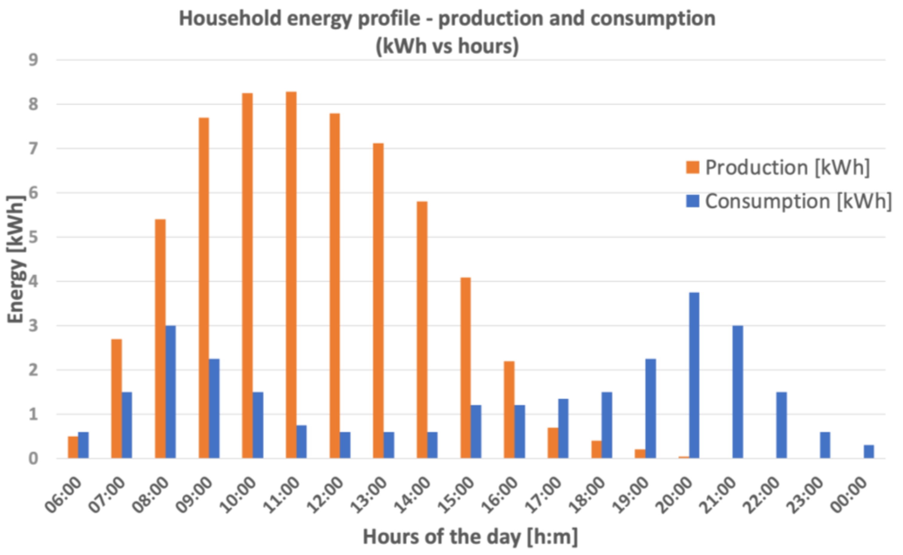
Figure 2.
Prosumer installation equipped with a hybrid inverter, photovoltaic installation, battery storage, and energy measurement at the point of common coupling.
Figure 2.
Prosumer installation equipped with a hybrid inverter, photovoltaic installation, battery storage, and energy measurement at the point of common coupling.

Figure 3.
Proposed hybrid inverter topology.

Figure 4.
Control strategy of AC/DC converter for on-grid operation.
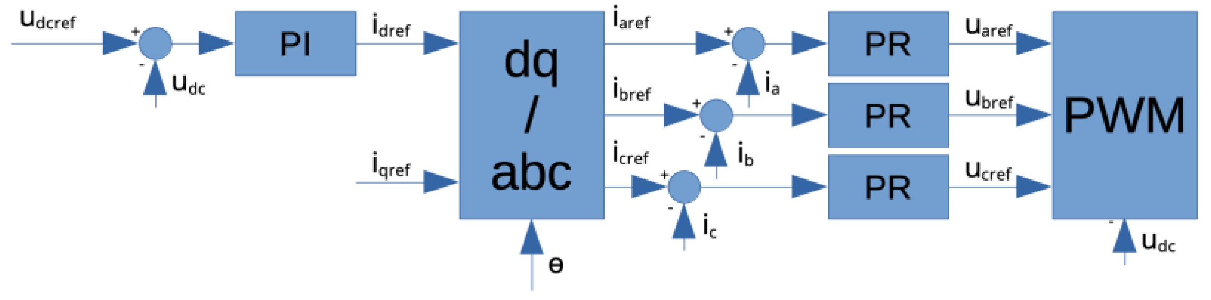
Figure 5.
Control strategy of AC/DC converter for off-grid operation.
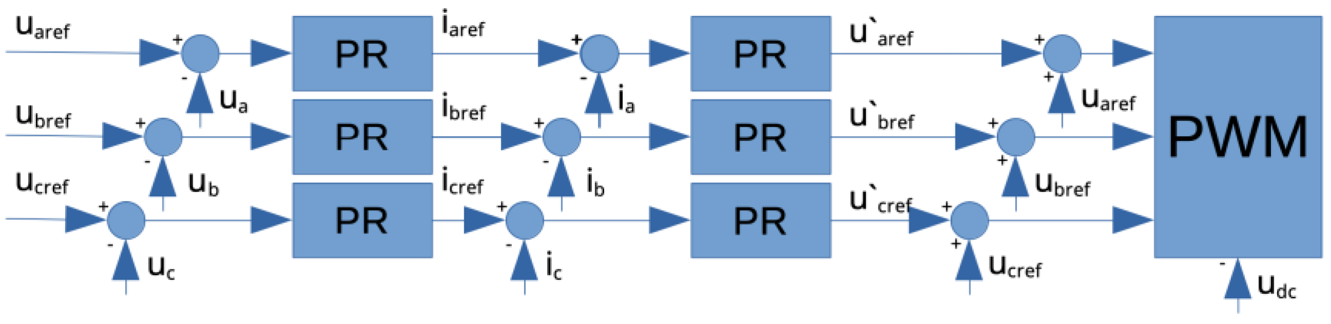
Figure 6.
Control strategy of DC/DC converter used for battery charging/discharging.
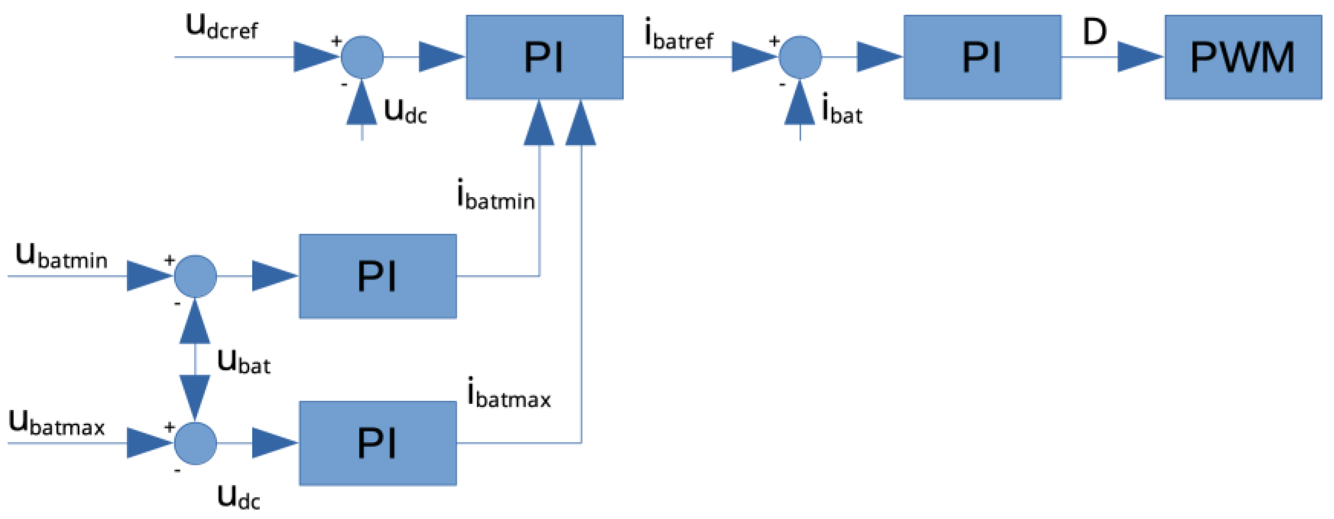
Figure 7.
Simulation model of analyzed 4-leg, 3-level AC/DC converter module with control strategy developed in PLECS; (a) power circuit of the converter, (b) control algorithm based on VOC implemented in PLECS.
Figure 7.
Simulation model of analyzed 4-leg, 3-level AC/DC converter module with control strategy developed in PLECS; (a) power circuit of the converter, (b) control algorithm based on VOC implemented in PLECS.
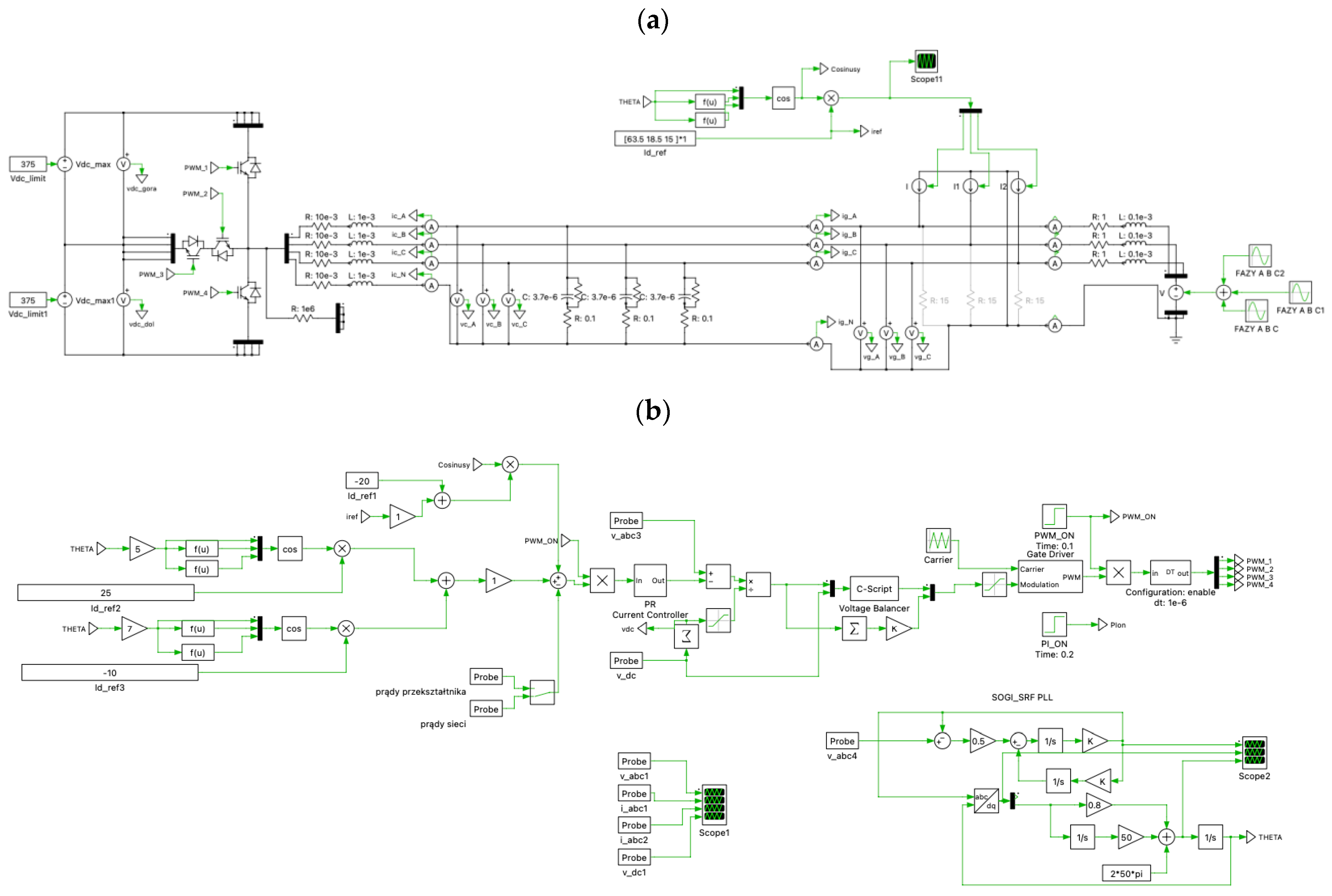
Figure 8.
Operation of the AC/DC converter in the static state, supplying the load connected to the AC grid from a renewable source and stabilizing the grid voltage dip: (a) the converter is not operating, and the load is connected to the grid and is powered directly by the grid; (b) the converter operates and transmits energy to the grid to power the connected load; (c) a 30% dip occurs in one phase, and the load is supplied by the converter. From the top: grid voltages at the point of common coupling (PCC), grid currents, converter currents, converter power (for individual phases).
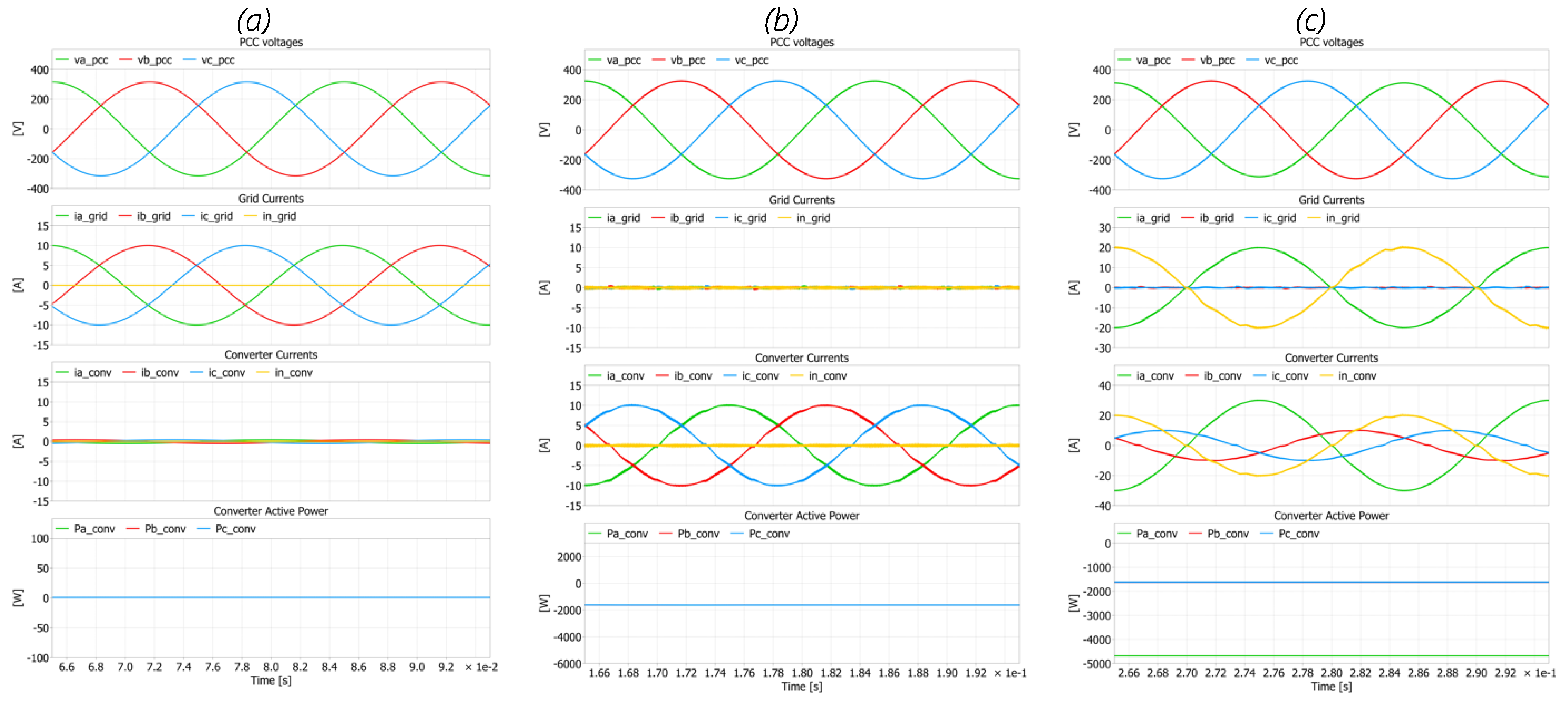
Figure 9.
Operation of the AC/DC grid converter to stabilize the grid voltage in the dynamic state: (a) operation of the source, which increases the grid voltage with the converter operating. In the last part of the waveform, the grid stabilization algorithm is activated (lowering the voltage), which results in increasing the converter currents and reducing the effective value of the grid voltage; (b) operation of the grid stabilization algorithm when a 30% voltage dip occurs in one of the phases. The operation of the stabilization algorithm is visible through the increased and asymmetric currents of the analyzed AC/DC converter. From the top: grid voltages, grid currents, converter currents, converter power (for individual phases).
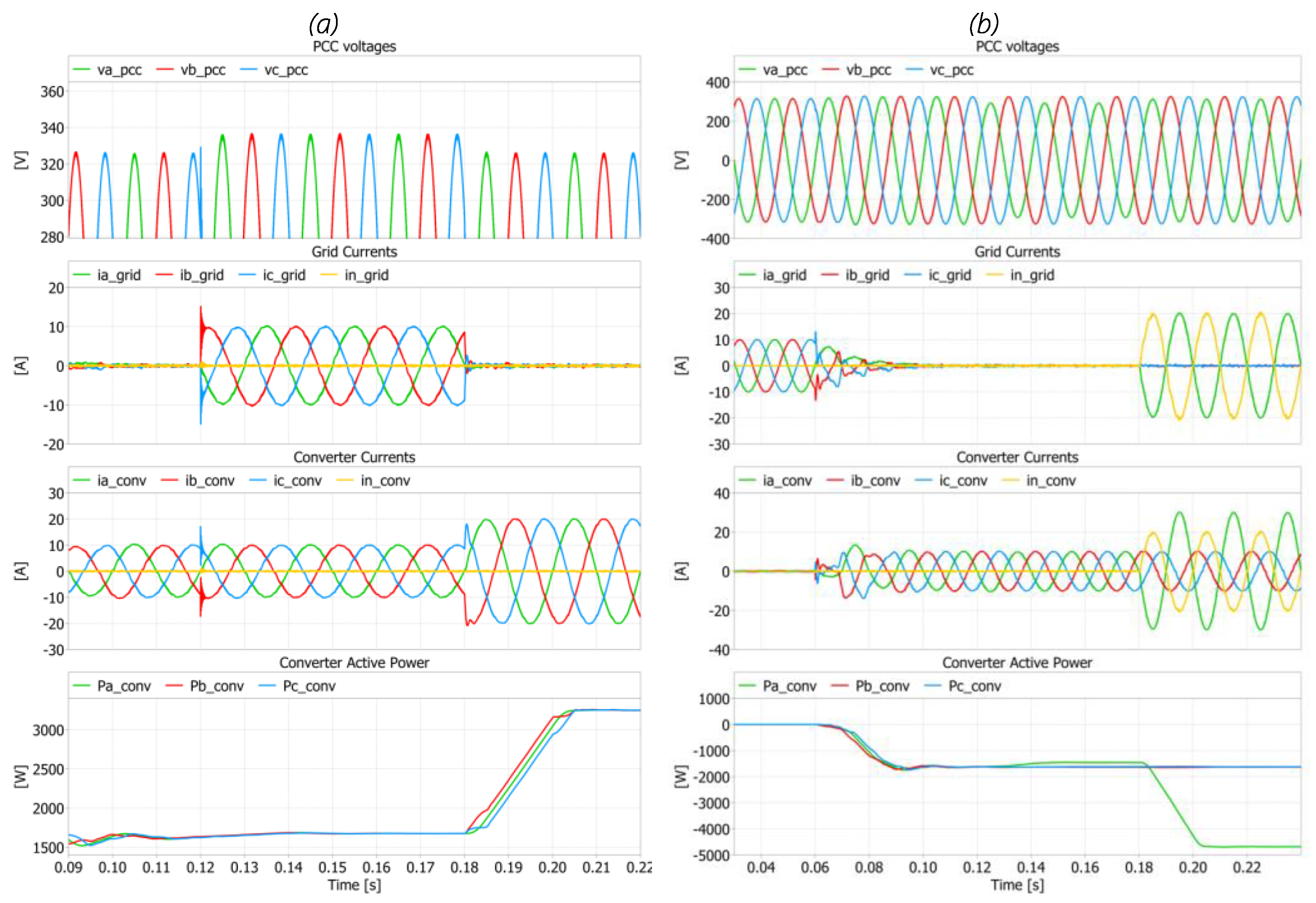
Figure 10.
View of the experimental setup used during research analysis, consisting of hybrid inverter, LFP battery, load used for off-grid operation, Yokogawa WT1800 Precision Power Analyzer, Yokogawa DL850 grid analyzer (Yokogawa Test & Measurement Corporation, Tokyo, Japan) PV source, and oscilloscopes.

Figure 11.
Operation of the hybrid inverter during steady state in off-grid mode with asymmetrical load. From the top: grid current and voltage, battery current, battery voltage, local load voltage, local load current.
Figure 11.
Operation of the hybrid inverter during steady state in off-grid mode with asymmetrical load. From the top: grid current and voltage, battery current, battery voltage, local load voltage, local load current.
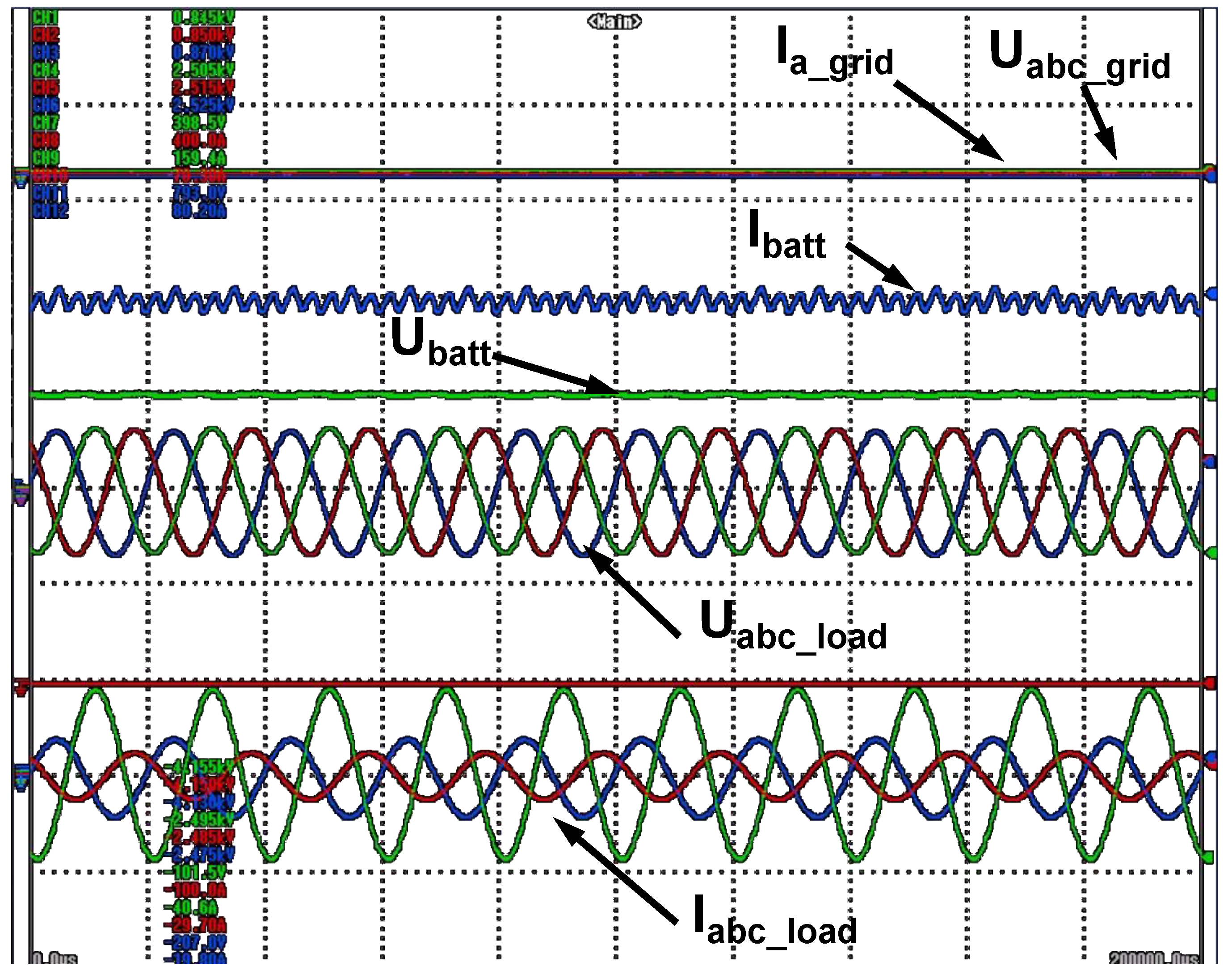
Figure 12.
Operation of the hybrid inverter during step change in operation modes: from on-grid and battery charging to off-grid and battery discharging. From the top: (a) battery voltage, battery current, PV voltage, PV current; (b) grid current and voltage of one phase and voltage and current of local load (one phase).

Figure 13.
Operation of the hybrid inverter during step change in operation modes: from on-grid and battery charging to off-grid and battery discharging on asymmetrical load. From the top: (a) battery voltage, battery current, PV voltage, grid voltage of one phase; (b) local load voltage of one phase and current of local load.
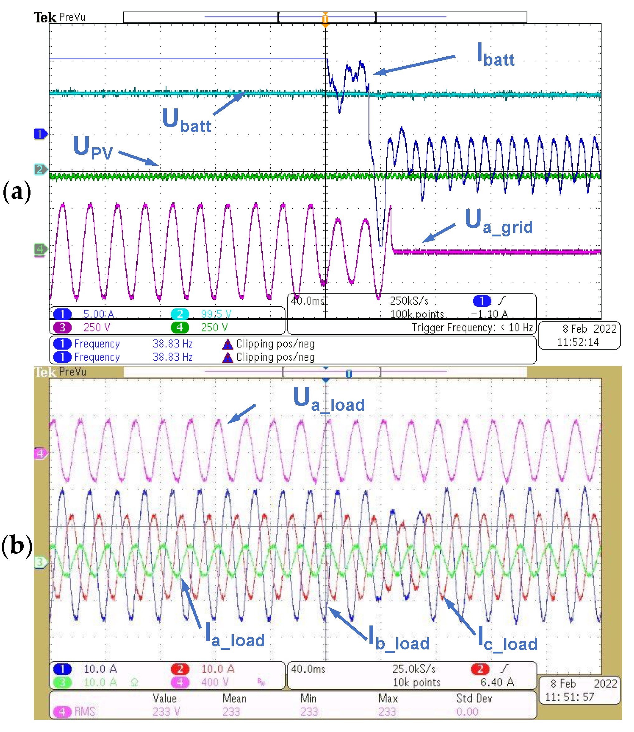
Figure 14.
Scheme of the test bench for efficiency analysis of the hybrid inverter; (a) operation with renewable source—PV panels; (b) operation with battery for charging and discharging modes.
Figure 14.
Scheme of the test bench for efficiency analysis of the hybrid inverter; (a) operation with renewable source—PV panels; (b) operation with battery for charging and discharging modes.

Figure 15.
Efficiency characteristics of the analyzed hybrid inverter.


Table 1.
Basic parameters of the analyzed hybrid inverter.
| Symbol | Parameter | Value |
|---|---|---|
| UPV | PV-side voltage range | 60–900 V DC |
| UMPPT | MPPT voltage range | 120–850 V DC |
| IPV-MAX | PV max current | 2 × 15 A |
| UOUT | Output voltage | 3 × 400 V, 50 Hz |
| IOUT | Output nominal current | 18 A |
| fsw | Switching frequency | 16/32 kHz |
| POUT | Nom. power of AC/DC converter | 12 kW |
| UBAT, IBAT | Battery voltage/current | 48–600 V/50 A |
| PBAT | Battery nominal power | 10 kW |
| Operation modes | on-grid/off-grid | |
| AC/DC converter topology | 4-leg, 3-level | |
| Power switches | IGBT (AC/DC), SiC (DC/DC) |
Disclaimer/Publisher’s Note: The statements, opinions and data contained in all publications are solely those of the individual author(s) and contributor(s) and not of MDPI and/or the editor(s). MDPI and/or the editor(s) disclaim responsibility for any injury to people or property resulting from any ideas, methods, instructions or products referred to in the content. |
© 2023 by the authors. Licensee MDPI, Basel, Switzerland. This article is an open access article distributed under the terms and conditions of the Creative Commons Attribution (CC BY) license (https://creativecommons.org/licenses/by/4.0/).
Share and Cite
MDPI and ACS Style
Piasecki, S.; Bachman, S.; Zaleski, J.; Jasinski, M.; Turzyński, M. AC-DC-DC Converter for Small Power Energy Storage Systems. Energies 2023, 16, 7556. https://doi.org/10.3390/en16227556
AMA Style
Piasecki S, Bachman S, Zaleski J, Jasinski M, Turzyński M. AC-DC-DC Converter for Small Power Energy Storage Systems. Energies. 2023; 16(22):7556. https://doi.org/10.3390/en16227556
Chicago/Turabian StylePiasecki, Szymon, Serafin Bachman, Jarosław Zaleski, Marek Jasinski, and Marek Turzyński. 2023. "AC-DC-DC Converter for Small Power Energy Storage Systems" Energies 16, no. 22: 7556. https://doi.org/10.3390/en16227556
Note that from the first issue of 2016, this journal uses article numbers instead of page numbers. See further details here.