
Analysis of Offline Transient Power Oscillation and Its Suppression Method in the Microgrid with Multiple Virtual Synchronous Generators
School of Electrical Engineering, Chongqing University, Chongqing 400044, China
*
Author to whom correspondence should be addressed.
Energies 2023, 16(23), 7711; https://doi.org/10.3390/en16237711
Submission received: 17 October 2023
/
Revised: 7 November 2023
/
Accepted: 13 November 2023
/
Published: 22 November 2023
(This article belongs to the Special Issue Advanced Control in Microgrid Systems II)
Abstract
:When multiple Virtual Synchronous Generators (VSGs) operate in parallel in an islanded grid, power and frequency oscillations will occur when one VSG goes offline. However, the existing literature does not cover the related analysis and transient suppression schemes for this scenario. To analyze these complex high-order system dynamics, this paper first establishes an intuitive equivalent circuit model for multiple VSGs, and the frequency domain expressions of the multi-machine VSG system during the VSG offline transient simulation are then derived. Based on the multi-VSG model and its transient oscillations analysis, this paper further proposes a configuration scheme for the equivalent circuit parameters. Equivalently, the virtual inertia, damping coefficient and virtual impedance of the VSGs can be configured. With the proposed parameter configuration scheme, the power oscillation during the VSG offline transient can be eliminated, as verified by experiments with a microgrid lab platform using three VSGs. Compared with the existing multi-VSG studies, the proposed scheme is not only the first attempt to study the transient suppression when a VSG goes offline, but also is more intuitive in analysis and less complicated in the controller parameter tuning.
1. Introduction
In recent years, distributed energy sources have come to constitute a large proportion of the power system capacity [1,2,3], which has introduced a large number of power electronic converters into the grid. As the existing grid-tied power converters mostly use current source control, the overall equivalent inertia and frequency stability of modern power systems are greatly reduced [4,5]. To address this concern, scholars have proposed Virtual Synchronous Generator (VSG) technology [6,7,8,9,10,11,12], which provides inertia and damping to the grid by simulating the motion equations of a synchronous generator. Therefore, the power electronic converters will have the same external characteristics as synchronous generators. Meanwhile, VSG-based power converters can seamlessly transition from grid-tied mode to off-grid mode, readily establishing the voltage and frequency of an islanded microgrid.
As VSGs inherit the same electromagnetic characteristics as synchronous generators, their output power and frequency will also oscillate during the transient processes. As power-electronics-based VSGs are far more fragile than synchronous generators to excessive power oscillations, VSG transient studies and suppression methods attract significant research interest.
So far, most of the research [13,14,15,16,17,18,19,20,21,22] has been carried out in a grid-tied scenario. Herein, even though multiple VSGs are usually tied to the grid in practice, the transients have been analyzed in this literature with a single VSG given a nearly infinite capacity grid. First, various VSG models have been proposed for transient analysis, such as the small signal model in [13], the sequence-impedance-based model in [14] and the state space models in [15] and [16]. Then, based on those models, VSG transient characteristics have been further investigated. In [17,18,19,20], the power oscillations are suppressed by adjusting the inertia or droop coefficient to maintain critical damping for the VSG. In [21], an online damping correction method utilizing optimal control design is implemented to enhance the transient characteristics of the VSG. Another method suggested in [22] is the use of generalized droop control to improve the power response characteristics.
As for the research on off-grid scenarios, the previous simplification using a single VSG is clearly not sustainable, as the coupling between multiple VSGs very much complicates the power transient mechanism. Therefore, multi-VSG analytical models must be established for multi-VSG off-grid transient analysis. In [23], a state space model of a parallel VSG system was established, based on which a damping method is also proposed to adjust the VSG droop and inertia coefficients, and a virtual damping method is also proposed. In [24], dynamic power sharing among multiple VSGs for droop control and VSG control was studied. In [25], a two-parallel VSG model was established, and a method of alternating the virtual inertia is proposed to suppress the power oscillation. In [26], the relationship between the output power and angular acceleration is analyzed, and a damping strategy is proposed using acceleration control coupled with disturbance compensation. In [27,28], an additional compensator is added to the active power loop to improve the transient performance of the multi-VSG system.
All the existing studies on multi-VSG transient suppression as discussed above are only about the scenario of load perturbation within the microgrid. However, there is an equally common scenario in a multi-VSG microgrid of having one or more existing VSGs go offline. This, unfortunately, has not been studied in any literature so far.
On the other hand, the existing analytical methods for multi-VSG systems are far from intuitive, making either the controller parameter tuning very complicated, or introducing side-effects like system frequency stability reduction. Moreover, these two VSG-model-based analysis and suppression methods are not readily extendible to systems with greater numbers of VSGs.
In this paper, the first attempt is made to study multi-VSG system transient suppression when s VSG goes offline. In doing so, more intuitive analytical models for multi-VSG systems are established, and the resulting transient suppression scheme is less complicated in its controller parameter tuning. The key contributions of this paper are summarized as follows.
- Establishes an equivalent RLC circuit model for VSGs, which is more intuitive and scalable than existing multi-VSG analysis based on state space equations and other modeling methods. The VSG offline transient expressions of multi-VSG systems are then easily derived.
- Discovers that the third-order oscillatory term in the output power expression is the root cause of the power oscillations during the VSG offline transient process.
- Proposes a configuration scheme for the equivalent circuit parameters to eliminate the resonance in the paralleled equivalent RLC circuits. Equivalently, the virtual inertia, damping coefficient and virtual impedance of VSGs are configured to eliminate the power oscillation in multi-VSG systems.
- An experimental platform with a three-VSG-based microgrid is constructed, and a significant improvement of the power oscillation during the VSG offline transient process is obtained with the proposed parameter configuration scheme.
The rest of the paper is organized as follows. In Section 2, the equivalent circuit model of a multi-VSG system is established. In Section 3, the VSG offline transient process in a multi-VSGs system is analyzed intuitively with the resonance in its equivalent circuits, which inspires the proposed parameter configuration rule. Section 4 presents the experimental results. Section 5 concludes the paper.
2. Multi-VSG System Modeling
2.1. VSG Fundamentals
Figure 1 shows the topology and control block diagram of the VSG. The distributed generation unit is connected to the converter dc-side capacitor, and the DC voltage stabilization is controlled by a separate DC-DC converter; therefore, the control of the DC-side voltage is not considered in this paper. In Figure 1, Lf, Lg and C are the filter inductors and filter capacitor; the converter output current iLabc and capacitor voltage VCabc are used as the inputs of the V-I control and the inputs of power calculation.
The core aim of the VSG control algorithm is to simulate the rotor equations of motion and reactive droop characteristics of the synchronous generator, as shown in Equation (1):
In Equation (1), Pset and Qset are the active input and reactive input reference values, Pout and Qout are the active output and reactive output calculated by the controller, ωm is the inverter output voltage angular frequency, ω0 is the reference angular frequency, Dp and J are the damping coefficient and inertia coefficient of VSG active control loop, respectively, E0 represents the rated output voltage amplitude, Uref represents the reference voltage amplitude and Dq represents the droop coefficient of the reactive loop.
Figure 1 also employs a virtual impedance in the control loop, which makes the output impedance of the VSG predominantly inductive and guarantees the decoupling of active and reactive power controls [22,29,30].
As in any other literature on VSG control, to simplify the model for power oscillation analysis, the following assumptions are made: (1) the coupling between the active and reactive loops is neglected and the active loop can be analyzed separately; (2) the control bandwidth of the converter voltage and the current in the double closed loop are much larger than the power loop bandwidth; (3) the system impedance of the inverter is small, which makes the voltage phase angle difference between inverter and the common AC bus very small [13].
2.2. Equivalent Circuit Model of VSG Active Loop
According to Equation (1) and [22], the small-signal model of the active loop in the VSG control strategy can be illustrated as in Figure 2.
In Figure 2, Kp = 3E0Ubus/X is the synchronization coefficient, where X is the sum of the actual and virtual impedances of VSG, E0 is the output voltage of VSG, Ubus is the AC bus voltage and ωbus is the frequency disturbance.
According to Figure 2, the two open-loop transfer functions can be written using Equation (2):
In [31], the VSG power control is represented with an equivalent electric circuit model. However, this equivalent model has not been used to derive the multi-VSG transient suppression methods. In this paper, the equivalent circuit representation is further arranged as a second-order RLC circuit, as shown in Figure 3a, for the intuitive analysis of the new scenario of the VSG offline transients within a multi-VSG microgrid, and the suppression method can be derived. The voltage and current in Figure 3a satisfy the relationship in Equation (3):
Comparing Equations (2) and (3), it can be seen that the power–frequency relationship in the VSG has a similar expression to the current–voltage relationship in this second-order RLC circuit. Therefore, the RLC second-order circuit can be used to equate the active power loop of the VSG. The correspondence between the VSG control and RLC circuit is shown in Figure 3b. According to the correspondence in Figure 3b, the active power in the active loop is equivalent to the current in the second-order circuit, the angular frequency change is equivalent to the voltage, the virtual inertia J is equivalent to the capacitance and the droop factor D is equivalent to the conductance. Therefore, J suppresses the frequency change in the same way that the capacitor stabilizes the circuit voltage, and D determines the angular frequency change in the output power in the same way that the conductance determines the voltage change with the current in the circuit.
According to the correspondence in Figure 3b, the circuit analysis methods can be used to analyze the mechanism of power oscillation, making the analysis of the multi-VSG system an intuitive process, as shown in Figure 4. Herein, isetn and in are the command and the output currents of the equivalent circuit of the nth VSG. isetn should be set as 0 in microgrid off-grid operations. iload is the load current within the microgrid.
3. Analysis and Suppression of VSG Offline Transients
In this section, the VSG offline transient in a multi-VSG system is analyzed intuitively with the resonance in its equivalent circuits. Since nodal voltage equations for circuit analysis can be established, each branch’s current expression can then be easily obtained. Then, by further factoring out the high-order oscillatory term, the equivalent circuit resonance can be quantitatively analyzed, which inspires the subsequent circuit parameter configuration rule derivation. Likewise, the VSG parameters can be configured to eliminate the power oscillation during the VSG offline transient. Combined with the system frequency stability requirements, the VSG parameters can then be easily selected.
3.1. Analysis of VSG Offline Transient Process
The analysis of the active power oscillation in a multi-VSG system when a VSG goes offline is equivalent to the circuit problem shown in Figure 5.
First, the original multi-VSG system and its equivalent circuit are in the steady state, when the inductors are considered as short circuits, and the capacitors are considered as open circuits. The steady-state currents through the inductors are derived using Equation (4), and are labeled in Figure 5.
Herein, these steady-state current values are determined by the current division among the conductance of each paralleled RLC equivalent circuit. These steady-state values are also the initial values for the VSG offline transient.
The output of the VSG3 equivalent circuit is opened up at the moment of 0_. Then, the s-domain equivalent circuit for the VSG offline transient analysis is established as in Figure 6.
Thus, the nodal voltage equations in the s-domain using node 4 as the reference can be written in the form Ax = B following Equations (5) and (6):
and
Note that if the multi-VSGs system has four or more VSGs, the s-domain equivalent circuits in Figure 6 can be easily extended by adding the RLC equivalent circuit from Figure 3. For example, when one VSG goes offline in a four-VSG system, the nodal voltage equation can also be established based on the extended s-domain equivalent circuits. However, in this scenario, the nodal voltage equation will have one more order than Equations (5) and (6).
According to Equations (5) and (6), each branch’s current expression can be easily obtained. Herein, the s-domain expression for i2 can be obtained as follows:
where α, β, γ and δ are defined as:
Then, according to the final value theorem, the steady-state value in Equation (7) can be obtained as follows:
Therefore, Equation (7) can be factorized as the steady-state expression and the transient expression using Equation (10):
The transient expression factored out from Equation (10) is a third-order oscillatory term, which corresponds to the power oscillations during the VSG offline process.
For quantitative analysis of the VSG offline transient process, the transients when VSG3 goes offline are plotted in Figure 7 and Figure 8. These two figures show the simulation results of the equivalent circuit.
In Figure 7a, the evolution of the i2 transients is plotted as C2 in the VSG2 equivalent circuit is varied. Herein, the G2 and L2 are fixed as 8000 S and 1 × 10⁻⁵ H. Meanwhile, C1, G1 and L1 are 1000 F, 4000 S and 2 × 10⁻⁵ H, respectively. As shown in Figure 7a, as C2 decreases, the overshoots of the output current decrease first and increase again in the opposite direction. The initial currents remain unchanged because L1 and L2 are both fixed. Meanwhile, the steady-state current also remains unchanged because G1 and G2 are both fixed.
In Figure 7b, the evolution of the capacitor voltage u2 transients is plotted. As C2 increases, the gradient of u2 becomes smaller. Meanwhile, the gradient of u1 in the first 0.1s of the transient process remains unchanged because C1 is fixed. As shown in the zoom-in view embedded in Figure 7b, when C2 = 8000 F, the gradient difference between u1 and u2 is slightly larger than C2 = 500 F, corresponding to the larger overshoot seen in Figure 7a.
In Figure 8, the evolution of the i2 transients is plotted as L2 in the VSG2 equivalent circuit is varied. Herein, the G2 and C2 are fixed at 8000 S and 2000 F. Meanwhile, the VSG1 parameters stay the same. As shown in Figure 8, the initial value of i2 is determined by L2, while the steady-state currents remain unchanged because G1 and G2 are both fixed. When L2 is progressively smaller than L1 (2 × 10⁻⁵ H), the initial value of i2 becomes increasingly higher than its steady-state value. When L2 is progressively higher than L1 (2 × 10⁻⁵ H), the initial value of i2 becomes smaller than its steady-state value.
It must be clarified that the transient trends’ evolution is investigated with separate parameter variation; in Figure 7, only C2 is varied while the other parameters are fixed, and in Figure 8, only L2 is varied and the other parameters are fixed. It must also be clarified that it is the ratios between the parameters of multiple VSGs that determine how bad the oscillation is, as seen in the third-order oscillatory term in Equation (10). Therefore, in this example, with VSG3 going offline, the parameters of either VSG1 or VSG2 can be varied to achieve the same ratio change and the resulting evolution in the transient trends.
3.2. Configuration of VSG Equivalent Circuit Parameters to Eliminate Offline Transient
As for the third-order transient expression factored out from Equation (10), its numerator and denominator have the same order. Therefore, in this paper we propose configuring their coefficients in order to cancel out these two polynomials. Thereby, this high-order oscillatory term in Equation (10) can be eliminated. In other words, the numerator must be equal to the denominator as expressed by Equation (11):
By expanding the polynomial on the left side of Equation (11), its coefficients can be equalized to the corresponding coefficients on the right side as in Equations (12)–(15).
where the expressions of α, β, γ and δ are taken from Equation (8). Then Equations (12)–(14) are further derived.
Equation (12) can be further derived as
Then, by substituting Equation (16) into Equation (13), it is derived that
With Equations (16) and (17), Equation (14) is also validated.
As shown in Equations (16) and (17), the ratios of the capacitances should be equal to the ratios of conductance and the reverse of the inductance ratios. With the parameters configured as in Equations (15) and (16), the equivalent circuit will have an ideal step change from its initial state to the steady state after a VSG goes offline, i.e., the output currents’ oscillation in the parallel equivalent circuits is eliminated.
The simulation in Figure 9 used the parameters set out in Table 1, which are configured according to Equations (16) and (17). It is shown that the output current instantly comes to the new steady state without oscillation. Meanwhile, the rate of change of capacitor voltage of VSG1 and VSG2 becomes the same.
According to the equivalence illustrated in Figure 3, the VSG parameters J, D and X can be configured accordingly to eliminate the multi-VSG power oscillation during the VSG offline transient.
Meanwhile, these VSG parameters also need to be set up according to the system’s requirements.
Therefore, the selection of the virtual inertia J of the VSG should be chosen considering the limits of the Rate of Change of Frequency (RoCoF), as in Equation (18):
where the minimum J is used to limit the RoCoF in case of the worst-case power step from zero to its rated value Si, and the factor kJi is a constant in the range of [1, 1.2], which adds a design margin of up to 20%.
Meanwhile, the selection of the droop factor D should be carried out considering the maximum frequency variation under the VSG full load, as in Equation (19):
where Δfmax can be set as ±0.5 Hz, according to the national standard for small power systems (less than 3 GW), and kDi is added as a design margin up to 20%.
In Equations (18) and (19), the subscript i indicates the serial number of the VSG in a multi-VSG microgrid. Therefore, the power oscillation during VSG offline transient can be simply eliminated by setting all the VSGs with the same kJi and kDi. It should also be noted that Xi should be inversely proportional to each VSG capacity according to Equation (16).
4. Experimental Verification
In order to validate the proposed analysis of the VSG offline transient for multi-VSG system and the effectiveness of the proposed parameter configuration scheme, lab tests are performed on the three-VSG microgrid platform, as shown in Figure 10. Herein, bi-directional battery simulators are used as the DC source of VSG, and external inductors are used to change the line impedances. The communication between DSP and the host computer is conducted via the CAN protocol so that the real-time output power and frequency of each VSG are transmitted back to the supervisory control GUI panel. Meanwhile, the output currents of the three VSGs are captured with an oscilloscope.
The main parameters of the multi-VSG setup are shown in Table 2, where Lfi, Lgi, Ci are the filter inductors and filter capacitor of the ith VSG, defined in Figure 1. Note that the capacity of VSG2 is twice that of VSG1 and VSG3.
The specific experimental procedure was as follows.
VSG1 establishes the grid voltage for the AC bus first. VSG2 and 3 are started next to synchronize with the VSG1. When all three VSGs operate in synchronism, a 20 kW load is switched on. Then, with different parameter configurations, VSG3 is turned off;the power oscillations and the phase currents of VSG1 and 2 are recorded in Figure 11.
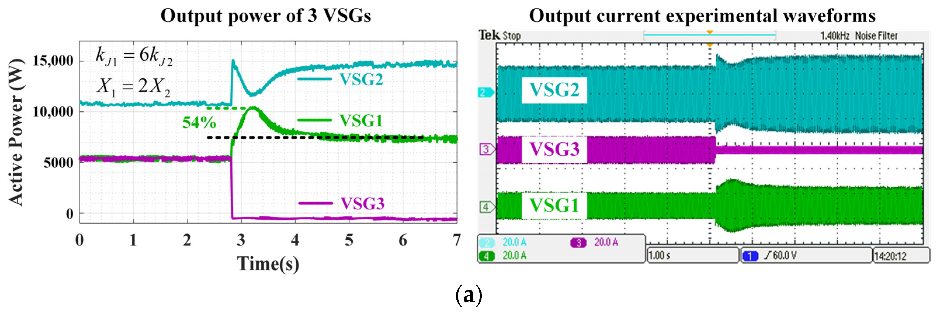
In all the subfigures of Figure 11, the experimental waveforms of the output power of the three VSGs are shown on the left side, and the A-phase current waveforms of the three VSGs are shown on the right side. Clearly, the oscillatory patterns of the output power waveforms correspond well to the envelopes of the A-phase current waveforms.
Figure 11a shows the experimental waveform for the case of kJ1 = 6kJ2, X1 = 2X2. Xi has been set to be inversely proportional to each VSG’s capacity, which satisfies the parameter configuration scheme. However, when kJ1 = 6kJ2, the virtual inertia configuration is far removed from the parameters defined in (18) and (19), and there is a more than 50% overshoot during the VSG offline process. Note that this parameter mismatch scenario, as in Figure 11a, is equivalent to the case of C2 = 8000, as in Figure 7a. Comparing Figure 7a with Figure 11a, the power waveform of VSG1 in the experiment has the same trend as the current waveform of C2 = 8000 case shown in Figure 7a.
Figure 11b shows the experimental waveform for the case of kJ1 = kJ2, 3X1 = X2. Herein, the virtual inertia has been set to be proportional to each VSG’s capacity, which satisfies the parameter configuration scheme. However, when 3X1 = X2, the virtual inductance configuration is far removed from the parameters defined in (18) and (19). Thus, there is a more than 70% overshoot during the VSG offline process. Note that this parameter mismatch scenario, as shown in Figure 11b, is equivalent to the case of L2 = 2 × 10⁻⁵/4, as in Figure 8a. Comparing Figure 8a with Figure 11b, the power waveform of VSG1 in the experiment has the same trend as the current waveform of L2 = 2 × 10⁻⁵/4 case shown in Figure 8a. By comparing Figure 11a,b with the simulation results, the prior theoretical analysis was validated.
5. Conclusions
This study is the first attempt to investigate an important but not yet studied scenario in the multi-VSG microgrid, i.e., the transients when one or more existing VSGs go offline. The equivalent RLC circuits-based multi-VSG models established in this paper were proven to be more intuitive and scalable than existing multi-VSG analysis based on state space equations and other modeling methods. It was also revealed that the third-order oscillatory term in the VSG offline transient output power expression is the root cause of the VSG offline transients. This discovery inspired a configuration scheme for equivalent circuit parameters to eliminate the resonance in the paralleled equivalent RLC circuits. Likewise, the configuration of the VSG parameters eliminated the power oscillation in the multi-VSG system with much less controller parameter tuning efforts by comparison. The multi-VSG experimental platform used three VSGs, which had more VSGs and a higher power than the two-VSG lab setup used in the existing literature. Compared with the simulation, the experimental data showed identical trends, and the proposed method significantly reduced the power overshoot during VSG offline transient. In future studies, the equivalent circuit-based multi-VSG models in this paper could also be applied to existing studies on multi-VSG transient suppression during microgrid load perturbation.
Author Contributions
Conceptualization, L.S. and B.Y.; methodology, L.S.; validation, L.S. and B.Y.; formal analysis, L.S.; investigation, L.S. and B.Y.; writing—original draft preparation, L.S.; writing—review and editing, S.L.; supervision, S.L.; project administration, L.S. All authors have read and agreed to the published version of the manuscript.
Funding
This research received no external funding.
Data Availability Statement
Data are contained within the article.
Conflicts of Interest
The authors declare no conflict of interest.
References
- Shuai, Z.; Sun, Y.; Shen, Z.J.; Tian, W.; Tu, C.; Li, Y.; Yin, X. Microgrid stability: Classification and a review. Renew. Sustain. Energy Rev. 2016, 58, 167–179. [Google Scholar] [CrossRef]
- Markovic, U.; Stanojev, O.; Aristidou, P.; Vrettos, E.; Callaway, D.S.; Hug, G. Understanding Small-Signal Stability of Low-Inertia Systems. IEEE Trans. Power Syst. 2021, 36, 3997–4017. [Google Scholar] [CrossRef]
- Zhang, W.; Cantarellas, A.M.; Rocabert, J.; Luna, A.; Rodriguez, P. Synchronous Power Controller With Flexible Droop Characteristics for Renewable Power Generation Systems. IEEE Trans. Sustain. Energy 2016, 7, 1572–1582. [Google Scholar] [CrossRef]
- Fang, J.; Li, H.; Tang, Y.; Blaabjerg, F. On the Inertia of Future More-Electronics Power Systems. IEEE J. Emerg. Sel. Top. Power Electron. 2018, 7, 2130–2146. [Google Scholar] [CrossRef]
- Sun, P.; Xu, H.; Yao, J.; Chi, Y.; Huang, S.; Cao, J. Dynamic Interaction Analysis and Damping Control Strategy of Hybrid System with Grid-forming and Grid-following Control Modes. IEEE Trans. Energy Convers. 2023, 38, 1639–1649. [Google Scholar] [CrossRef]
- Zhong, Q.-C.; Weiss, G. Synchronverters: Inverters that Mimic Synchronous Generators. IEEE Trans. Ind. Electron. 2011, 58, 1259–1267. [Google Scholar] [CrossRef]
- Pan, D.; Wang, X.; Liu, F.; Shi, R. Transient Stability of Voltage-Source Converters With Grid-Forming Control: A Design-Oriented Study. IEEE J. Emerg. Sel. Top. Power Electron. 2020, 8, 1019–1033. [Google Scholar] [CrossRef]
- Li, C.; Yang, Y.; Cao, Y.; Wang, L.; Blaabjerg, F.; Dragicevic, T. Frequency and Voltage Stability Analysis of Grid-Forming Virtual Synchronous Generator Attached to Weak Grid. IEEE J. Emerg. Sel. Top. Power Electron. 2020, 10, 2662–2671. [Google Scholar] [CrossRef]
- Abuagreb, M.; Ajao, B.; Herbert, H.; Johnson, B.K. Evaluation of Virtual Synchronous Generator Compared to Synchronous Generator. In Proceedings of the 2020 IEEE Power & Energy Society Innovative Smart Grid Technologies Conference (ISGT), Washington, DC, USA, 17–20 February 2020; pp. 1–5. [Google Scholar]
- Li, M.; Wang, Y.; Hu, W.; Shu, S.; Yu, P.; Zhang, Z.; Blaabjerg, F. Unified Modeling and Analysis of Dynamic Power Coupling for Grid-Forming Converters. IEEE Trans. Power Electron. 2021, 37, 2321–2337. [Google Scholar] [CrossRef]
- Duan, Q.; Zhao, C. Improved VSG Controlled SST in a Low-Voltage AC Distribution Network. In Proceedings of the 2021 IEEE Sustainable Power and Energy Conference (iSPEC), Nanjing, China, 23–25 December 2021; pp. 428–435. [Google Scholar]
- Lei, J.; Xiang, X.; Liu, B.; Li, W.; He, X. Quantitative and Intuitive VSG Transient Analysis With the Concept of Damping Area Approximation. IEEE Trans. Smart Grid 2023, 14, 2477–2480. [Google Scholar] [CrossRef]
- Wu, H.; Ruan, X.; Yang, D.; Chen, X.; Zhao, W.; Lv, Z.; Zhong, Q.-C. Small-Signal Modeling and Parameters Design for Virtual Synchronous Generators. IEEE Trans. Ind. Electron. 2016, 63, 4292–4303. [Google Scholar] [CrossRef]
- Wu, W.; Zhou, L.; Chen, Y.; Luo, A.; Dong, Y.; Zhou, X.; Xu, Q.; Yang, L.; Guerrero, J.M. Sequence-Impedance-Based Stability Comparison Between VSGs and Traditional Grid-Connected Inverters. IEEE Trans. Power Electron. 2018, 34, 46–52. [Google Scholar] [CrossRef]
- Harnefors, L.; Hinkkanen, M.; Riaz, U.; Rahman, F.M.M.; Zhang, L. Robust Analytic Design of Power-Synchronization Control. IEEE Trans. Ind. Electron. 2018, 66, 5810–5819. [Google Scholar] [CrossRef]
- Liu, J.; Miura, Y.; Ise, T. Comparison of Dynamic Characteristics Between Virtual Synchronous Generator and Droop Control in Inverter-Based Distributed Generators. IEEE Trans. Power Electron. 2016, 31, 3600–3611. [Google Scholar] [CrossRef]
- Alipoor, J.; Miura, Y.; Ise, T. Stability Assessment and Optimization Methods for Microgrid With Multiple VSG Units. IEEE Trans. Smart Grid 2016, 9, 1462–1471. [Google Scholar] [CrossRef]
- Alipoor, J.; Miura, Y.; Ise, T. Power System Stabilization Using Virtual Synchronous Generator With Alternating Moment of Inertia. IEEE J. Emerg. Sel. Top. Power Electron. 2014, 3, 451–458. [Google Scholar] [CrossRef]
- Li, D.; Zhu, Q.; Lin, S.; Bian, X.Y. A Self-Adaptive Inertia and Damping Combination Control of VSG to Support Frequency Stability. IEEE Trans. Energy Convers. 2016, 32, 397–398. [Google Scholar] [CrossRef]
- Hu, W.; Shen, Y.; Lun, J.; Yang, F.; Zhao, S. Study on Secondary Non-Differential Frequency Modulation Control Strategy of VSG in Islanding Mode. IEEE Access 2023, 11, 116979–116989. [Google Scholar] [CrossRef]
- Zhang, X.; Mao, F.; Xu, H.; Liu, F.; Li, M. An optimal coordination control strategy of micro-grid inverter and energy storage based on variable virtual inertia and damping of vsg. Chin. J. Electr. Eng. 2017, 3, 25–33. [Google Scholar]
- Meng, X.; Liu, J.; Liu, Z. A Generalized Droop Control for Grid-Supporting Inverter Based on Comparison Between Tradi-tional Droop Control and Virtual Synchronous Generator Control. IEEE Trans. Power Electron. 2019, 34, 5416–5438. [Google Scholar] [CrossRef]
- Liu, J.; Miura, Y.; Bevrani, H.; Ise, T. Enhanced Virtual Synchronous Generator Control for Parallel Inverters in Microgrids. IEEE Trans. Smart Grid 2016, 8, 2268–2277. [Google Scholar] [CrossRef]
- Paquette, A.D.; Reno, M.J.; Harley, R.G.; Divan, D.M. Sharing Transient Loads: Causes of Unequal Transient Load Sharing in Islanded Microgrid Operation. IEEE Ind. Appl. Mag. 2013, 20, 23–34. [Google Scholar] [CrossRef]
- Chen, M.; Zhou, D.; Wu, C.; Blaabjerg, F. Characteristics of Parallel Inverters Applying Virtual Synchronous Generator Control. IEEE Trans. Smart Grid 2021, 12, 4690–4701. [Google Scholar] [CrossRef]
- Shuai, Z.; Huang, W.; Shen, Z.J.; Luo, A.; Tian, Z. Active Power Oscillation and Suppression Techniques Between Two Parallel Synchronverters During Load Fluctuations. IEEE Trans. Power Electron. 2019, 35, 4127–4142. [Google Scholar] [CrossRef]
- Li, M.; Yu, P.; Hu, W.; Wang, Y.; Shu, S.; Zhang, Z.; Blaabjerg, F. Phase Feedforward Damping Control Method for Virtual Synchronous Generators. IEEE Trans. Power Electron. 2022, 37, 9790–9806. [Google Scholar] [CrossRef]
- Rathnayake, D.B.; Razzaghi, R.; Bahrani, B. Generalized Virtual Synchronous Generator Control Design for Renewable Power Systems. IEEE Trans. Sustain. Energy 2022, 13, 1021–1036. [Google Scholar] [CrossRef]
- Yang, D.; Ruan, X.; Wu, H. Using virtual impedance network to improve the control performances of LCL-type grid-connected inverter under the weak grid condition. In Proceedings of the 2014 IEEE Applied Power Electronics Conference and Exposition—APEC 2014, Fort Worth, TX, USA, 16–20 March 2014; pp. 3048–3054. [Google Scholar]
- Li, C.; Yang, Y.; Cao, Y.; Aleshina, A.; Xu, J.; Blaabjerg, F. Grid Inertia and Damping Support Enabled by Proposed Virtual Inductance Control for Grid-Forming Virtual Synchronous Generator. IEEE Trans. Power Electron. 2022, 38, 294–303. [Google Scholar] [CrossRef]
- Qin, B.; Xu, Y.; Yuan, C.; Jia, J. A Unified Method of Frequency Oscillation Characteristic Analysis for Multi-VSG Grid-Connected System. IEEE Trans. Power Deliv. 2021, 37, 279–289. [Google Scholar] [CrossRef]
Figure 1.
Topology and control block diagram of VSG.

Figure 2.
Power–frequency small-signal model of VSG.
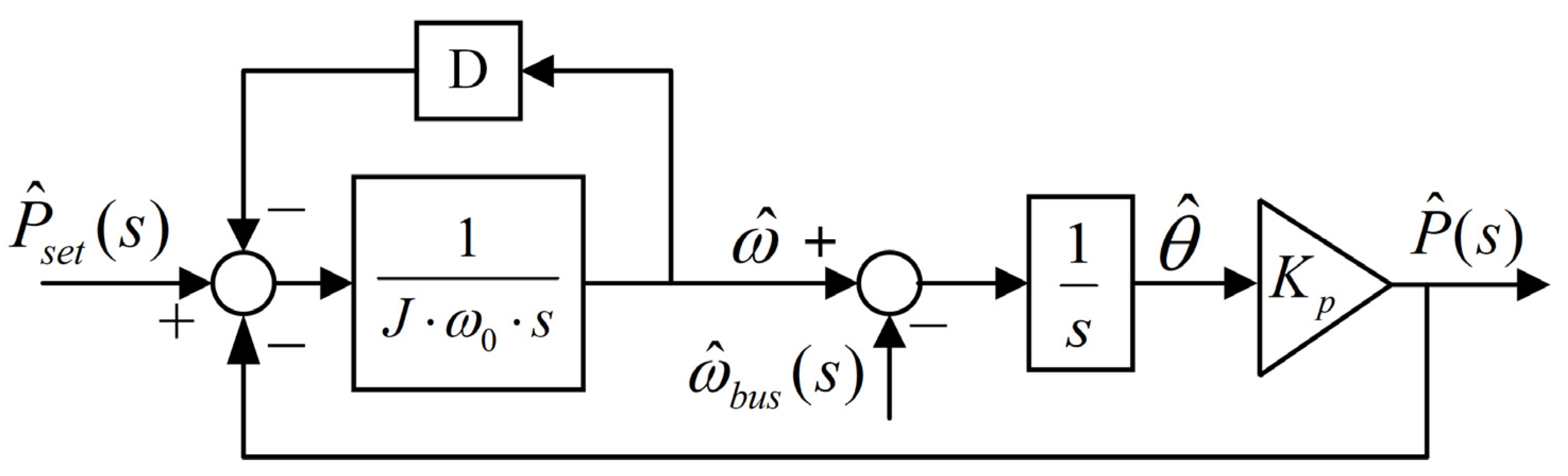
Figure 3.
Equivalent circuit model of VSG active power control. (a) A second-order RLC circuit. (b) The correspondence between the VSG control and the RLC circuit.
Figure 3.
Equivalent circuit model of VSG active power control. (a) A second-order RLC circuit. (b) The correspondence between the VSG control and the RLC circuit.
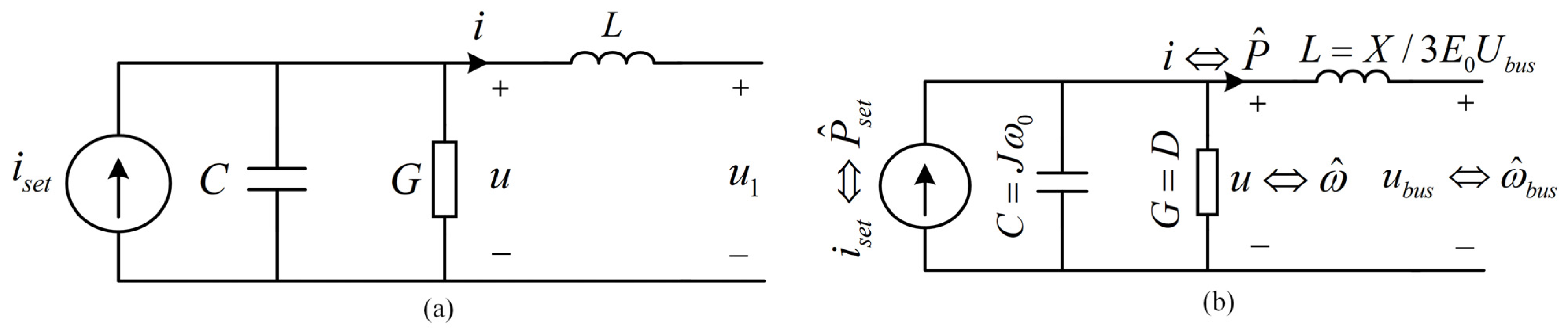
Figure 4.
Multi-VSG system equivalent circuit.
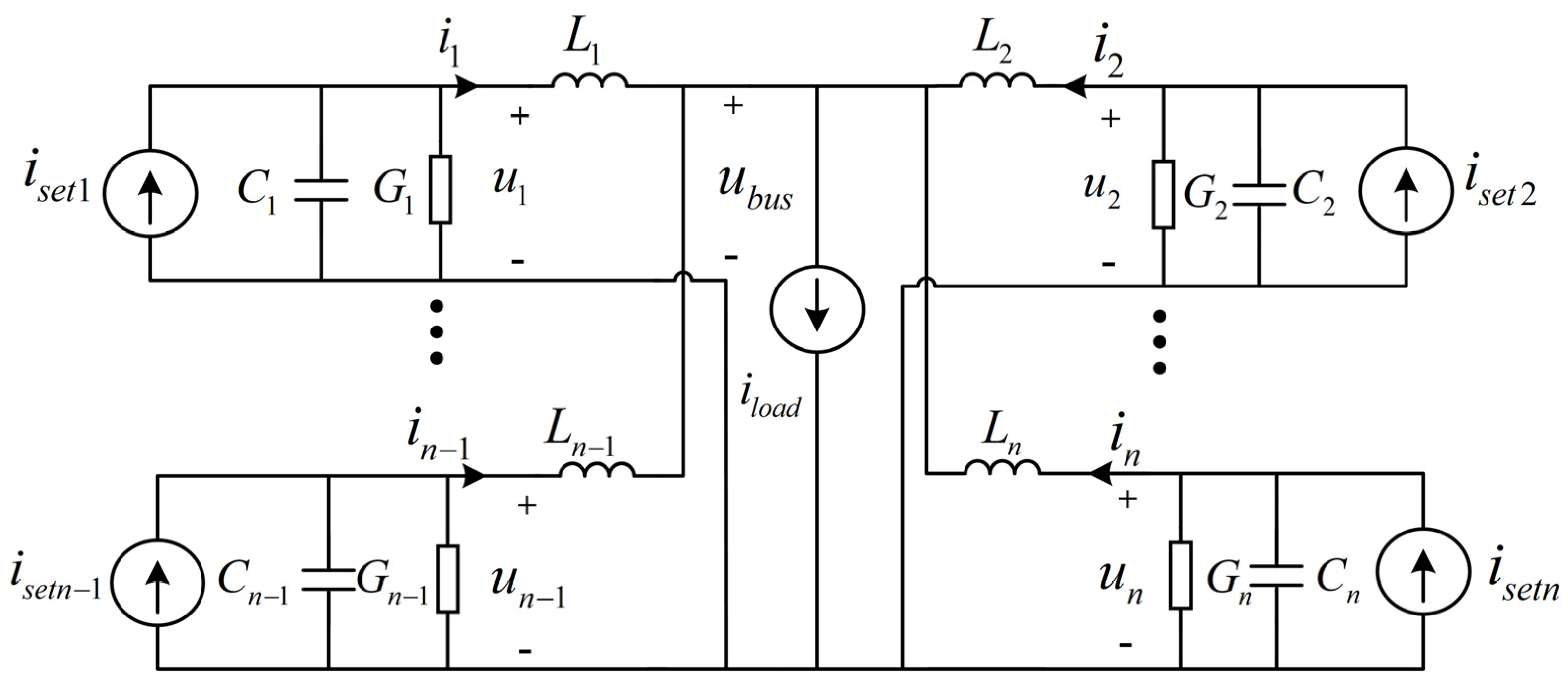
Figure 5.
The equivalent circuit of a multi-VSG system at steady state before VSG3 goes offline.

Figure 6.
The s-domain equivalent circuit for VSG offline transient analysis.
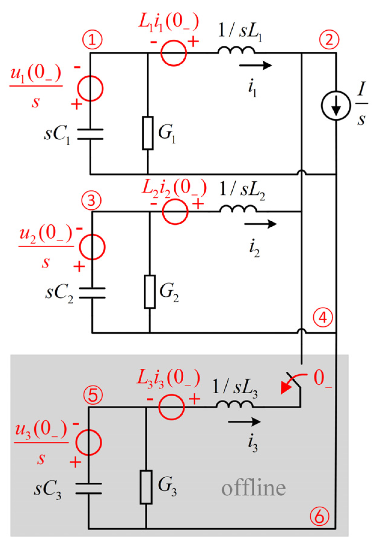
Figure 7.
Equivalent circuit resonance under varying capacitance (VSG3 goes offline). (a) Output current waveforms. (b) Capacitor voltage waveforms.
Figure 7.
Equivalent circuit resonance under varying capacitance (VSG3 goes offline). (a) Output current waveforms. (b) Capacitor voltage waveforms.

Figure 8.
Equivalent circuit output current oscillation under varying inductances (VSG3 goes offline).
Figure 8.
Equivalent circuit output current oscillation under varying inductances (VSG3 goes offline).
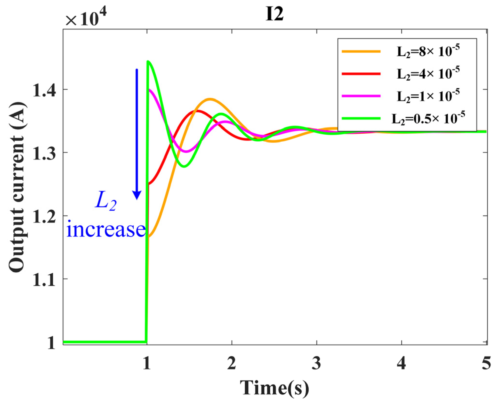
Figure 9.
Simulation results when both (15) and (16) are satisfied. (a) Output current waveforms. (b) Capacitor voltage waveforms.
Figure 9.
Simulation results when both (15) and (16) are satisfied. (a) Output current waveforms. (b) Capacitor voltage waveforms.

Figure 10.
Multi-VSGs microgrid experimental platform.

Figure 11.
Power oscillation of the VSG offline process with different parameter configurations. (a) kJ1 = 6kJ2, X1 = 2X2. (b) kJ1 = kJ2, 3X1 = X2. (c) the proposed parameter configuration scheme.
Figure 11.
Power oscillation of the VSG offline process with different parameter configurations. (a) kJ1 = 6kJ2, X1 = 2X2. (b) kJ1 = kJ2, 3X1 = X2. (c) the proposed parameter configuration scheme.


Table 1.
Parameters configuration using (15) and (16) for the three VSG’s equivalent circuits.
| Parameters | Ci (F) | Gi (S) | Li (H) | |
|---|---|---|---|---|
| Serial Number | ||||
| VSG1 | 2000 | 4000 | 2 × 10⁻⁵ | |
| VSG2 | 4000 | 8000 | 1 × 10⁻⁵ | |
| VSG3 | 2000 | 4000 | 2 × 10⁻⁵ | |
Table 2.
Main parameters of the experiment.
| Parameters | Value | Parameters | Value |
|---|---|---|---|
| E0 | 220 V | S1, S3 | 10 kVA |
| ω0 | 100 π rad/s | S2 | 20 kVA |
| RoCoF | 1 Hz/s | Lg1, Lg3 | 700 μH |
| ∆fmax | ±0.5 Hz | Lg2 | 1200 μH |
| fs | 20 kHz | Lf(1,2,3) | 300 μH |
| Pload | 20 kW | C(1,2,3) | 30 μF |
Table 3.
Parameters of the VSGs in the experiment.
| Parameters | J (kg·m2) | D (N·s/m) | X (Ω) | |
|---|---|---|---|---|
| Serial Number | ||||
| VSG1 | 1885 | 4000 | 1.9 | |
| VSG2 | 3770 | 8000 | 0.95 | |
| VSG3 | 1885 | 4000 | 1.9 | |
Disclaimer/Publisher’s Note: The statements, opinions and data contained in all publications are solely those of the individual author(s) and contributor(s) and not of MDPI and/or the editor(s). MDPI and/or the editor(s) disclaim responsibility for any injury to people or property resulting from any ideas, methods, instructions or products referred to in the content. |
© 2023 by the authors. Licensee MDPI, Basel, Switzerland. This article is an open access article distributed under the terms and conditions of the Creative Commons Attribution (CC BY) license (https://creativecommons.org/licenses/by/4.0/).
Share and Cite
MDPI and ACS Style
Shan, L.; Yang, B.; Lu, S. Analysis of Offline Transient Power Oscillation and Its Suppression Method in the Microgrid with Multiple Virtual Synchronous Generators. Energies 2023, 16, 7711. https://doi.org/10.3390/en16237711
AMA Style
Shan L, Yang B, Lu S. Analysis of Offline Transient Power Oscillation and Its Suppression Method in the Microgrid with Multiple Virtual Synchronous Generators. Energies. 2023; 16(23):7711. https://doi.org/10.3390/en16237711
Chicago/Turabian StyleShan, Liang, Bo Yang, and Shuai Lu. 2023. "Analysis of Offline Transient Power Oscillation and Its Suppression Method in the Microgrid with Multiple Virtual Synchronous Generators" Energies 16, no. 23: 7711. https://doi.org/10.3390/en16237711
Note that from the first issue of 2016, this journal uses article numbers instead of page numbers. See further details here.