
Classification and Design of Backfill Coal Mining Systems Based on Typical Engineering Cases
by
 , ,
, ,
Pengfei Cui
1,2, 
Qiang Zhang
1,2,*,
Kang Yang
1,2,
Haonan Lv
1,2,
Jinming Cao
1,2 and
Wei Wang
1,2 1
School of Mines, China University of Mining & Technology, Xuzhou 221116, China
2
State Key Laboratory of Coal Resources and Safe Mining, China University of Mining & Technology, Xuzhou 221116, China
*
Author to whom correspondence should be addressed.
Energies 2023, 16(24), 8074; https://doi.org/10.3390/en16248074
Submission received: 22 November 2023
/
Revised: 7 December 2023
/
Accepted: 12 December 2023
/
Published: 15 December 2023
(This article belongs to the Section H: Geo-Energy)
Abstract
:Backfill coal mining technology has drawn widespread attention due to its benefits of “controlling surface deformation and subsidence, reducing mining-induced disturbance in the stope, and recycling solid mine wastes”. However, the backfill coal mining technology is still progressing slowly in China. The geological environment of China’s mining areas is complex and highly diversified, and backfill coal mining is expected to fulfill different goals in a wide range of engineering scenarios. These facts explain the poor reproducibility of backfill coal mining projects. This study reviews the existing backfill coal mining systems in China. Based on findings from a survey of engineering cases, we summarize five types of new backfill coal mining methods classified by deployment style; namely, borehole grouting backfill, roadway backfill, borehole–roadway backfill, in situ backfill, and roadway-in-situ backfill. A total of 15 backfill coal mining methods falling into the above five categories are described. An engineering design workflow for backfill coal mining consisting of five steps is proposed; namely, identifying the targets of backfill, analyzing the feasibility of deploying the backfill system, comparing the engineering quantities of different engineering schemes, estimating the economic efficiency of backfill, and backfill performance tracking and monitoring. Real cases of backfill engineering design are analyzed to inform the fast and reasonable design of backfill strategy for specific working faces in certain coal mines.
1. Introduction
Coal has occupied a predominant position in the global energy market as a conventional energy source. As far as China is concerned, coal remains a ballast and a stabilizer in primary energy supply and consumption [1,2]. In recent years, there has been a growing awareness of “green, low-carbon, and sustainable development”, accompanied by strengthened environmental protection in coal mining. An evolution of environmental awareness has taken place in the coal mining sector, from “mining first and environmental governance later” and “post-mining repair” to “pre-mining prevention” and “hazard reduction from the source”. Backfill coal mining has received widespread attention since the technology better meets the new requirements of the coal mining industry by limiting post-mining overburden migration and disposing of solid mine wastes in an environmentally friendly way [3,4]. However, China is still at the initial stage of research on backfill coal mining and has a long way to go before establishing a mature technology system for backfill. China’s coal mines have some unique features rarely observed in other parts of the world, such as the diversity of backfill targets, environmental variabilities of the mining area, complexity of geological conditions, and a deepening of coal seam mining, which results in low reproducibility of coal mine backfill engineering. This partially explains the slow progress in backfill coal mining technology and the absence of mature backfill technology that can be applied extensively [5,6]. According to survey data, as of May 2023, 13 out of 26 provinces in China with coal mines have adopted or plan to adopt backfill mining, involving 60 mining group companies and 95 coal mines, accounting for about 5% of the national mines, which is generally low.
Addressing the pain points in the coal mining sector, we first review the backfill coal mining methods currently in use, which can be classified into several categories. Then, based on findings from the survey of backfill engineering cases, we innovatively propose five types of backfill systems depending on their deployment style. A total of 15 backfill systems belonging to the above five categories are described. Furthermore, an engineering design workflow for backfill coal mining consisting of five steps is recommended. This method can inform the backfill strategy’s fast and reasonable design of a backfill strategy for a specific working face in a coal mine.
2. Backfill Coal Mining Concept and Classification
2.1. Concept of Backfill Coal Mining
Backfill coal mining is a method that involves establishing a stable support system composed of coal pillars, fill bodies, and supports after backfilling the stope during the coal mining process [7,8]. This technology can offer extraordinary benefits, such as limiting post-mining overburden migration, controlling surface deformation and subsidence, alleviating mining-induced disturbances in the stope, recycling solid mine wastes, and realizing green and sustainable coal mine construction. Backfill coal mining is frequently used for mining under water bodies, railroads, and buildings, as well as above confined waters [9,10].
2.2. Classification of Backfill Coal Mining Methods in Use
The backfill coal mining techniques [11,12,13,14,15] can be classified in different manners if different features of backfill are prioritized over others: (1). Depending on the type of backfill material used, there are solid backfill, paste backfill, paste-like backfill, and high water backfill. The compression performance of the filling body is determined by various filling materials and their different ratios, which affects the control effect of the overlying rock. (2). Depending on the power driving the backfill, there are fully mechanized backfills, self-flow, pneumatic backfills, mechanized backfills, and hydraulic backfills (3). Depending on the backfill site, there are goaf backfills, backfills in the caving area, and backfills in the separation area (4). Depending on the ratio of mine and backfill, there are full mining and full filling (FM + FF), full mining and local filling (FM + LF), local mining and local filling (LM + LF), and local mining and full filling (LM + FF). The existing classification methods for backfill coal mining are shown in Figure 1. The concept and theories within backfill mining inform these classification methods for backfill coal mining. However, the classification results are sometimes partial and need more significant guidance for field engineering applications.
2.3. A survey of Engineering Cases of Backfill Coal Mining
To establish a more “practical” classification method for backfill coal mining, we have surveyed engineering cases of backfill coal mining in China [16,17,18,19,20,21]. We mainly focus on the coal mine’s backfill background, the type of mining process in the working face, and the deployment style of the backfill system. The survey results of backfill coal mining engineering cases are summarized, as shown in Table 1.
2.4. New Concepts for Classifying Backfill Coal Mining Methods
Summarizing and analyzing cases of backfill coal mining engineering, it is not hard to find that the backfill systems in each project have high similarities and reproducing space. This article innovatively proposes five types of backfill coal mining methods based on the deployment style of the backfill system; namely, borehole grouting backfill, roadway backfill, borehole–roadway backfill, in situ backfill, and in situ roadway backfill. Moreover, fifteen backfill coal mining methods belonging to these five types were further specified based on backfill targets, site of backfill, and type of backfill material used. The new concepts for classifying available backfill coal mining methods based on the deployment style are illustrated in Figure 2.
3. A Review of the Backfill Coal Mining Methods Classified by the Deployment Style
In engineering, a backfill system is a collective name for serial equipment, shaft engineering, and buildings and structures intended for collecting, preparing, and storing the backfill material, transporting the material to the site of backfill, and performing the backfill [22,23,24]. The backfill system is usually composed of three modules: material preparation, material storage and transport, and backfill in the mining face. The modules for material preparation and storage & transport are designed to meet the backfill requirements in the mining face. Therefore, deployment of the “backfill system in the mining face” should be the prioritized focus in the deployment design of the entire backfill system, while the other modules are designed to be compatible with the backfill module.
3.1. Deployment of the Borehole Grouting Backfill System
Borehole grouting backfill is defined as follows: Slurry grouting is performed via the borehole for the downward filling mining process drilled in the ground surface above the working face for backfilling the post-mining space. Depending on the site of backfill and the space to be filled, borehole grouting backfill is further divided into two types: borehole grouting backfill in the separation area and borehole grouting backfill in the caving area. The backfilling depth of the two methods is different; the former is shallower and intended to fill the dynamically changing separation area produced below the key strata after the mining of the working face; the latter is deeper and intended to fill the dynamically changing caving area produced right after the mining of the working face. Deployment of the borehole grouting backfill system is schematically presented in Figure 3.
The material used for borehole grouting backfill is usually a slurry that combines liquidity and stability. Fly ash and gangue are the most commonly used aggregates for preparing the slurry. The slurry is transported to the target site using a backfill pump or filling pipelines. The above steps require the construction of a slurry preparation station and the drilling of a grouting borehole on the ground. We need to purchase slurry preparation equipment, slurry transport pipelines, and a backfill pump to achieve these goals.
The borehole grouting backfill system should be deployed based on the following considerations: (1). Land is available for takeover for building the slurry preparation station and drilling a borehole; (2). The ground surface is suitable for borehole drilling. The presence of mountains, undulating, thick, unconsolidated formations, or weak overburden is not conducive to high-quality borehole drilling; (3). It must be ensured that the grouting space does exist and remains stable. The overburden conditions and the properties of key strata in the working face have a large bearing on the morphology and stability of the backfill space and, hence, affect the possibility of continuous grouting. Borehole grouting backfill has the following technical features: (1). High backfill performance but poor stability; (2). Low ability in solid mine waste disposal; (3). Relative independence of the backfill system and backfill procedure from the other procedures; (4). Technical simplicity.
3.2. Deployment of the Roadway Backfill System
Roadway backfill refers to the following: The coal body to be mined is first segmented into roadways for tunneling, and a backfill system is deployed for backfilling in the roadway after mining. Depending on the type of backfill material used, roadway backfill is further divided into gangue-throwing backfill in the roadway and grouting backfill in the roadway. For the former, solid mine wastes, such as gangue, are thrown into the roadway; the backfill materials are transported using a belt conveyor. A belt conveyor and gangue-throwing machine are needed to fulfill these functions, and no extra construction is required. For the latter, slurry with a high solid mass concentration is poured into the already extracted roadway. The backfill pump and the filling pipelines then transport the slurry. The above steps require the construction of a slurry preparation station and backfill retaining wall. Slurry preparation equipment, a slurry transport pipeline, and a backfill pump are needed to achieve these purposes. Deployment of the roadway backfill system is illustrated in Figure 4.
The roadway backfill system is deployed based on the following considerations: (1). The coal seam thickness is most of the tunneling roadway’s height. This method is particularly suitable for the tunneling–backfilling operation in the coal seam with a thickness below 5.0 m; (2). The roadway is allowed to have a small dip, which does not interfere with the safe operation of the tunneling machine. In addition, an appropriate dip angle in the roadway is conducive for gangue and slurry stack forming. This method is applicable for the tunneling–backfilling operation in a coal seam with a dip angle of about 18°; (3). The roadway space is intact and stable, making it suitable for deploying the roadway backfill system and executing the tunneling-backfilling operation. The roadway backfill has the following technical benefits. (1). Gangue-throwing backfill in the roadway can achieve unstably high performance, while the grouting backfill in the roadway achieves high and stable performance. (2). Gangue-throwing backfill in the roadway has a higher ability to dispose of solid mine wastes while grouting backfill in the roadway is less capable of disposing of solid mine wastes. (3). The backfill system and workflow are flexibly adjustable. (4). The backfill process is technically simple. (5). The engineering quantity is small.
3.3. Deployment of the Roadway–Borehole Backfill System
The borehole–roadway backfill refers to the following: A borehole is drilled, or a pipeline is laid in the post-mining space in the working face from a nearby roadway, followed by grouting. Depending on the positions of the roadway and borehole (or pipelines) relative to the working face, there are five methods for borehole–roadway backfill, namely, in situ backfill in the current roadway, high-position backfill in the current roadway, in situ backfill in the adjacent roadway, high-position backfill in the adjacent roadway, and backfill through the strata in the roof roadway. An in situ backfill in the current roadway is performed to backfill the dynamically changing goaf formed by mining in the working face deployed along the in situ backfill pipeline in the current extraction roadway; high-position backfill in the current roadway is used to backfill the dynamically changing caving area formed by mining in the working face deployed along the borehole for high-position backfill in the current extraction roadway; in situ backfill in the adjacent roadway is used to backfill the dynamically changing goaf formed by mining in the working face deployed along the in situ backfill borehole in the adjacent extraction roadway; high-position backfill in the adjacent roadway is used to backfill the dynamically changing caving area formed by mining in the working face deployed along the borehole for high-position backfill in the adjacent extraction roadway; backfill through the strata in the roof roadway is used to backfill the dynamically changing caving area formed by mining in the working face deployed along the strata-crossing borehole in the high-position (typically “roof extraction”) roadways. The roadway–borehole backfill usually requires the arrangement of filling boreholes or pipelines in advance, and grouting can start at a certain distance (about 5–10 steps) after mining in the working face. The slurry that combines fluidity and stability is preferably used for borehole–roadway backfill. The slurry is transported using the backfill pump and backfill pipeline. The above steps require the construction of a slurry preparation station and the drilling of a grouting borehole. Slurry preparation equipment, a slurry transport pipeline, and a backfill pump are needed. Deployment is illustrated in Figure 5.
The borehole–roadway backfill system should be deployed based on the following considerations. (1). There is an appropriate backfill roadway, and the current roadway is relatively stable, or there is an adjacent roadway or roof roadway suitable for extraction in succession near the working face. (2). Drilling a borehole in the roof is feasible, whereas weak and soft direct roofs and overburden are unsuitable for drilling a high-quality borehole. Borehole–roadway backfill has the following technical features: (1). Poor backfill performance and stability; (2). Low ability in solid mine waste disposal; (3). Simple backfill process; (4). Flexibly adjustable and highly adaptable; (5). Small engineering quantity.
3.4. Deployment of the In Situ Backfill System
In situ backfill refers to the following: The coal body is entirely or locally excavated in the mining block. The resulting goaf is subject to full solid stowing or local filling. Depending on the ratio of mine and backfill, there are four different methods for in situ backfill: full mining and full filling, full mining and local filling, local mining and local filling, and local mining and full filling. The deployment of the in situ backfill system is illustrated in Figure 6.
Whatever the method, in situ backfill is to fill the dynamically changing goaf formed by extraction in the working face. Solids or slurry can be chosen as the filling material and transported using belt conveyors or filling pipelines. When solids are used as the filling material, constructing a crushing plant, feeding shaft, and belt corridor is usually required, along with purchasing the belt conveyor, crushing machine, and wear-resistant pipes. When the slurry is used as the filling material, a slurry preparation station is usually required, along with the purchase of slurry preparation equipment, a slurry transport pipeline, and a backfill pump. A filling diagram for solid and paste backfill working face is shown in Figure 7.
The in situ backfill system should be deployed based on the following considerations: (1). The mining thickness is not too large; the backfill height of the slurry is maximally about 3 m, and the backfill height of solids is maximally about 5 m; (2). The system is suitable for recycling residual coal pillars. The in situ backfill has the following technical features: (1). High backfill performance and stability; (2). High ability in disposing of solid mine wastes; (3). Higher level of technical complexity; (4). Despite the parallel deployment of the backfill system, the mining and filling operations proceed at different speeds, ultimately lowering the production efficiency; (5). Larger upfront investment.
3.5. Deployment of the In Situ Roadway Backfill System
In situ roadway backfill refers to the following: Two roadways and cut holes are deployed along the strike of a fully mechanized mining face in longwall mining. Next, the coal body in the working face is divided into several branch roadways along the strike at a specific interval (about 4 to 6 m). One mining and filling segment is designated for every 2 to 4 branch roadways, and the method of “one mining segment and one filling segment for every Nth segment” is established. The in situ roadway backfill is particularly suitable for mining coal seams with poor roof lithology (strength) or shallow coal seams. Depending on the type of backfill material used, there are two methods for in situ roadway backfill: continuous mining and continuous filling with gangue-throwing backfill and continuous mining and continuous filling with grouting backfill. The in situ roadway backfill is similar to in situ backfill in terms of the position of backfill, backfill material and transport, engineering quantity, applicability, strengths, and defects. The only difference is that the former involves the succession of mining and filling in several branch roadways, which implies a higher level of complexity in the mining and filling system and workflow. Deployment of the in situ roadway backfill system with “one mining section for every four sections” taken as an example is illustrated in Figure 8.
4. Design Methods for Backfill Coal Mining and Engineering Cases
4.1. Engineering Design Methods for Backfill Coal Mining and Workflow
Backfill coal mining engineering is an integration of backfill technology and field experience. Engineers are expected to develop a backfill mining scheme that fits a specific working face in a coal mine and satisfies preset goals [25]. Based on the new classification of backfill coal mining methods by deployment style of the backfill systems, we propose an engineering design method for backfill coal mining consisting of five steps, namely, identifying the targets of backfill, analyzing the feasibility of deploying the backfill system, comparing the volumes of different engineering schemes, estimating the economic efficiency of backfill, and backfill performance tracking and monitoring. This method can inform a backfill strategy’s fast and reasonable design for a specific working face in a coal mine. The engineering design workflow for backfill coal mining is shown in Figure 9.
- (1)
- Identify the backfill targets
Based on actual needs in backfill, we first developed 3–5 backfill coal mining schemes that could achieve the desired purposes in theory and form an “ordered set of backfill schemes” by sorting them in ascending order of backfill performance. The sorting was determined based on the backfill performance analysis for different schemes, as shown in Table 1. The targets of backfill included the following ones: (1). To achieve higher backfill performance and stability to control surface deformation and subsidence and alleviate mine pressure in the stope; (2). To recycle solid mine wastes, such as gangue; (3). To recycle residual coal pillars.
- (2)
- Analyze the feasibility of backfill system deployment
The backfill coal mining schemes in the “ordered set” are executed under the specific conditions of a coal mine. The deployment of the backfill system is simulated, and a feasibility analysis is conducted. Those that are not feasible or are difficult to realize are excluded. Finally, an “ordered set of backfill schemes” is formed, and the optimal one is chosen according to the deployment conditions for each backfill system, as shown in Table 2. We are mainly concerned with the following geological conditions and mining conditions within the coal mines: surface topography of the coal body, enrichment conditions in the coal seam, mining scheme design in the working face, overburden distribution and properties, and mining succession of roadways. It should be noted that “stability” in the table specifically refers to the phenomenon of surface subsidence and deformation caused by the lagging deformation of the filling body after filling the working face.
- (3)
- Compare the engineering quantities of the schemes
The construction quantity, newly added equipment, and transport pipelines required for each backfill scheme are estimated. The items of engineering quantity analyzed for each backfill scheme are shown in Table 3. Notably, the parameters listed in the table are only related to the main part of the project. Refinement and quantification of each part of the construction project are required during the practical application of engineering.
- (4)
- Estimate the economic efficiency of backfill
The economic efficiency (consisting of engineering investment and engineering benefits) is estimated for each backfill scheme based on engineering quantity analysis. Next, the backfill schemes are compared by comprehensively evaluating the backfill performance (as ranked in the ordered set), engineering quantity, and economic efficiency.
- (5)
- Backfill performance tracking and monitoring
Backfill indicators are chosen and monitored based on the targets for backfill during the execution of the backfill schemes, including surface deformation, compression rate, amount of solid mine wastes disposed of, backfill-mining mass ratio, and working resistance of supports. The performance of the backfill in the selected schemes is assessed based on the above. At the same time, we are provided with positive feedback on the engineering parameter selection and process design of the selected backfill coal mining methods, further optimizing the theory and implementation of filling engineering technology.
4.2. Case Analysis of Backfill Engineering Design in Xingdong Coal Mine
Xingdong Coal Mine is in Xingtai City, in the Hebei Province of China [26,27]. The mining face designed is situated under buildings. The backfill scheme is intended to “strictly control surface deformation and subsidence”. Following the proposed workflow for backfill mining design, the order of the backfill schemes used to fulfill the backfill targets consists of in situ backfill, in situ roadway backfill, and borehole grouting backfill. The geological conditions and mining conditions within the coal mine are then analyzed, which reveals the following: (1). The ground surface above the working face is flat; (2). The burial depth of the working face is about 620 m, and several hard and thick key strata are identified in the overburden; (3). The direct roof of the working face is composed of sandy mudstone and lacks integrity; (4). The coal bodies to be mined in the mining face are residual coal pillars after strip mining, and the coal pillar is 58 m wide. The in situ roadway backfill is found infeasible for deployment and, therefore, excluded. Thus, the ordered set of backfill schemes is updated to consist of full mining and full filling as the technique for in situ backfill and borehole grouting backfill in the separation area as the technique for borehole grouting backfill. These two candidate backfill schemes are compared in terms of engineering quantity and economic efficiency, and the borehole grouting backfill in the separation area significantly outperforms full mining and full filling as a technique for in situ backfill.
Taken together, we provide the following suggestions for backfill engineering design in the Xingdong Coal Mine: In light of the protection requirements for surface buildings in the mining area, borehole grouting backfill in the separation area is better if the scheme can meet the backfill targets related to backfill performance and stability; otherwise, the full mining and full filling scheme will be more favored due to higher backfill performance and stability, despite its higher engineering investment and lower economic efficiency. Taking the full mining and full filling of gangue as an example, the deployment of the backfill system is shown in Figure 10. The filling system includes four parts: surface gangue storage and transportation system, aboveground and underground feeding system, underground transportation system and working face filling system. When designing the operation connection and capability of each system, it is necessary to ensure the continuous backfilling of the working face and avoid the delayed supply of filling materials affecting the efficiency of backfilling and coal discharge.
4.3. Case Analysis of Backfill Engineering Design in Bailongshan Coal Mine
Bailongshan Coal Mine, located in Qujing City, Yunnan Province of China [28,29], is a newly built coal mine with a large gangue production. However, Bailongshan Coal Mine is now faced with an inadequate amount of residual space in the gangue dump. In addition, only a small amount land is available for takeover as a nature reserve is located nearby. For this coal mine, the backfill mining scheme is designed mainly for “recycling the solid mine wastes, typically the gangue”. Following the proposed workflow for backfill mining design, the order of the backfill schemes used to fulfill the backfill targets consists of in situ backfill, in situ roadway backfill, gangue-throwing backfill, and borehole grouting backfill as techniques for roadway backfill, and borehole–roadway backfill. We further analyze the geological conditions and mining conditions of the coal mine, which reveals the following: (1). The ground surface above the working face is undulating and belongs to the mountainous area; (2). The working face has a thickness of 1.8 m, and the coal seam dip angle is 15°; (3). The roof of the working face is mainly composed of siltstone and has good stability; (4). A high-position gas extraction roadway is deployed at about 25 m from the roof of the working face; (5). Due to the extension of the boundary of the nature reserve, some roadways have been abandoned, resulting in a lack of roadways available for mining succession. In situ roadway backfill and borehole grouting backfill are infeasible for deployment and, therefore, excluded. The order of the backfill schemes is updated to consist of in situ backfill, gangue-throwing backfill as a technique for roadway backfill, and backfill through the strata in the roof roadway as a technique for borehole–roadway backfill. The remaining backfill schemes are compared regarding engineering quantity and economic efficiency, and the in situ backfill scheme is much inferior to other backfill schemes.
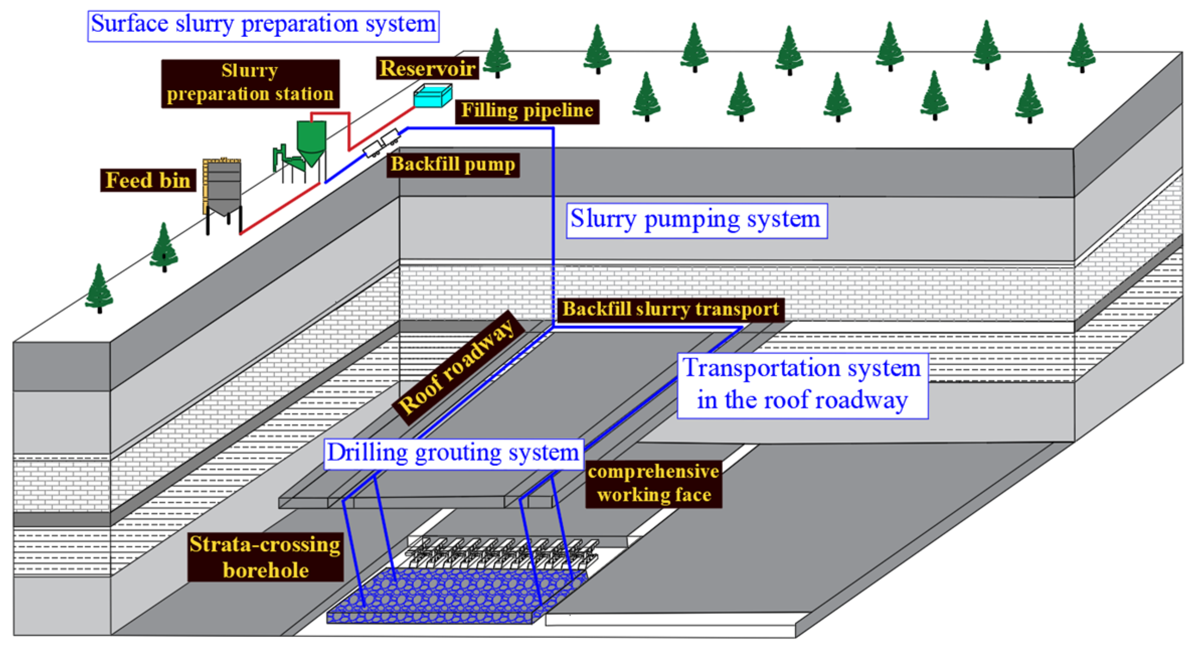
Taken together, we provide the following suggestions for backfill engineering design in Bailongshan Coal Mine: The gangue is better disposed of by backfill through the strata in the roof roadway. The abandoned roadways are also favorable sites for gangue disposal by gangue-throwing backfill in the roadway. Taking the backfilling through the strata in the roof roadway as an example, the deployment of the backfill system is shown in Figure 11. The filling system includes four parts: surface slurry preparation system, slurry pumping system, transportation system in the roof roadway and drilling grouting system. In actual engineering, the design of the backfilling pipeline has a total length of 102 km, a diameter of 168 mm, a drilling diameter of 32 mm, and a spacing of 280 m. The specific construction parameters are comprehensively considered in the design, taking into account factors such as mining conditions, filling space, and disposal volume.
5. Conclusions and Outlook
The results obtained made it possible to draw the following conclusions:
- (1)
- This study reviewed the existing backfill coal mining systems in China. Based on findings from a survey of engineering cases, we identified five main types of new backfill coal mining methods depending on deployment style: borehole grouting backfill, roadway backfill, borehole–roadway backfill, in situ backfill, and in situ roadway backfill.
- (2)
- Fifteen backfill techniques belonging to these five types were further identified; namely, borehole grouting backfill in the separation area, borehole grouting backfill in the caving area, gangue-throwing backfill in the roadway, grouting backfill in the roadway, in situ backfill in the current roadway, high-position backfill in the current roadway, in situ backfill in the adjacent roadway, high-position backfill in the adjacent roadway, backfill through the strata in the roof roadway, full mining and full filling, full mining and local filling, local mining and full filling, local mining and local filling, continuous mining and continuous filling with gangue-throwing backfill, and continuous mining and continuous filling with grouting backfill.
- (3)
- An engineering design method for backfill coal mining consisting of five steps was proposed; namely, identifying the targets of backfill, analyzing the feasibility of deploying the backfill system, comparing the volumes of different engineering schemes, estimating the economic efficiency of backfill, and backfill performance tracking and monitoring. This method was further applied to the case analyses of backfill engineering design in two coal mines in China; namely, the Xingdong Coal Mine and the Bailongshan Coal Mine.
The proposed approach has certain limitations that are expected to be mitigated in a follow-up study. Along with the extensive applications of backfill coal mining in China, deployment styles of the backfill system are expected to emerge in increasing quantities and quality to meet backfill engineering requirements in different mining areas and mines and under diversified conditions. This solves the problems and limitations within the existing filling system layout, such as the problem of delayed mining efficiency caused by the mismatch between surface backfilling speed and mining speed. In addition, we still have much to improve in the following aspects of backfill engineering design: establishing a standardized and practical workflow for backfill engineering design to make backfill engineering projects reproducible within a specific range, as well as promoting the continuous and healthy development of backfill coal mining in the coal mining sector.
Author Contributions
P.C. and Q.Z.: Methodology, Writing—original draft. K.Y. and H.L.: Supervision, Funding acquisition. J.C. and W.W.: Investigation. All authors have read and agreed to the published version of the manuscript.
Funding
This research received no external funding.
Data Availability Statement
Data are contained within the article.
Acknowledgments
The author gratefully acknowledge all the professors for their guidance and help during writing.
Conflicts of Interest
The authors declare no conflict of interest.
References
- Qian, M.; Xu, J.; Wang, J. Further on the sustainable mining of coal. J. China Coal Soc. 2018, 43, 1–13. [Google Scholar]
- Xie, H.P.; Wang, J.; Wang, G.F.; Ren, H.; Liu, J.; Ge, S.; Ren, S. New ideas of coal revolution and layout of coal science and technology development. J. China Coal Soc. 2018, 43, 1187–1197. [Google Scholar]
- Liu, J.; Li, X.; He, T. Application status and development of coal mine filling mining in China. Coal J. 2020, 45, 141–150. [Google Scholar]
- Miao, X.; Ju, F.; Huang, Y.; Guo, G. New progress and prospect of filling coal mining theory and technology. J. China Univ. Min. Technol. 2015, 44, 391–399+429. [Google Scholar]
- Xu, J.; Xuan, D.; Zhu, W.; Wang, X.; Wang, B. Research and practice of partially filled coal mining technology. J. Coal 2015, 40, 1303–1312. [Google Scholar]
- Qin, W.; Xu, J.; Xuan, D.; Ju, J.; Cheng, X. Research on green mining technology and economic evaluation method of coal mine. J. Min. Saf. Eng. 2023, 40, 1092–1101. [Google Scholar]
- Zhou, N.; Yao, Y.; Song, W. Present situation and prospect of gangue treatment technology in coal mine. J. Min. Saf. Eng. 2020, 37, 136–146. [Google Scholar]
- Tu, S.; Hao, D.; Li, W.; Liu, X. Theoretical and technical system construction of selective mining in ‘mining-selection-filling + X’ integrated mine. J. Min. Saf. Eng. 2020, 37, 81–92. [Google Scholar]
- Zhang, J.; Zhang, Q.; Zhou, N.; Li, M.; Huang, P. Research progress and prospect of coal-based solid waste filling mining technology. Coal J. 2022, 47, 4167–4181. [Google Scholar]
- Yang, K.; Zhao, X.; He, X.; Wei, Z. Basic theory and technical system of multi-source coal-based solid waste green filling. Coal J. 2022, 47, 4201–4216. [Google Scholar]
- Zhang, J.; Tu, S.; Cao, Y.; Tan, Y.; Xin, H. Intelligent separation and filling technology and engineering application of coal gangue in underground coal mine. J. China Univ. Min. Technol. 2021, 50, 417–430. [Google Scholar]
- Yuan, Y.; Zhu, C.; Wang, W. Method for optimizing the layout of coal mining-filling space in deep coal mines. J. China Univ. Min. Technol. 2023, 52, 286–299. [Google Scholar]
- Zhang, Q.; Yang, K.; Zhang, H.; Xia, K.; Zhang, Q. Study on the weakening law and characterization of pressure behavior in solid filling mining. J. China Univ. Min. Technol. 2021, 50, 479–488. [Google Scholar]
- Zhang, J.; Zhang, Q.; Ju, F.; Duan, Y.; Li, H. Theory and technique of greening mining integrating mining, separating and backfilling in deep coal resources. J. China Coal Soc. 2018, 43, 377–389. [Google Scholar]
- Jia, K.; Feng, G.; Wang, Y.; Duan, Y.; Li, H. Instability mechanism and prevention of super high water material bag filling body in inclined mining. J. China Univ. Min. Technol. 2015, 44, 409–415. [Google Scholar]
- Sun, J.; Wang, L.; Zhao, G. Stability criterion of aquiclude in strip filling overlying strata in Shendong special water-preserved mining coal seam. J. China Univ. Min. Technol. 2018, 47, 957–968. [Google Scholar]
- Zhang, J.; Zhou, N.; Gao, F.; Yan, H. Filling method of gangue grouting in subsequent space of coal mining. Coal J. 2023, 48, 150–162. [Google Scholar]
- Liu, J.; Bi, J.; Zhao, L. Research and application of automatic control of fully mechanized solid filling coal mining. Coal Sci. Technol. 2016, 44, 149–156. [Google Scholar]
- Xu, L.; Zhang, K.; Liu, X. Deformation characteristics and surface subsidence control effect of key strata in separated layer grouting mining. Coal J. 2023, 48, 931–942. [Google Scholar]
- Ma, L.; Wang, S.; Yu, Y. Technology and practice of wall-type continuous mining and water-preserved coal mining. J. Min. Saf. Eng. 2021, 38, 902–910+987. [Google Scholar]
- Zhang, J.X.; Ju, F.; Li, M.; Zhou, N.; Zhang, Q. Coal gangue underground separation collaborative in-situ filling mining method. Coal J. 2020, 45, 131–140. [Google Scholar]
- Zhang, J.; Zhang, Q.; Ju, F. Practice and technique of green mining with integration of mining, dressing, backfilling and X in coal resources. J. China Coal Soc. 2019, 44, 64–73. [Google Scholar]
- Xie, H.; Zhang, J.; Gao, F.; Li, B.; Li, C. Theory and technical conception of negative carbon efficient filling mining in coal mine. Coal J. 2023, 11, 23. [Google Scholar]
- Xu, W.; Chen, W.; Zhang, Y.; Chen, B. Study on rheological properties of gangue-fly ash slurry in deep filling mining. Coal Sci. Technol. 2023, 51, 85–93. [Google Scholar]
- Huang, Y.; Zhang, J.; Du, J. Study on time-dependent characteristics of filling body in fully mechanized solid filling coal mining. J. China Univ. Min. Technol. 2012, 41, 697–701. [Google Scholar]
- Gao, P. Key technology research and engineering demonstration of filling mining under construction in Xingdong Mine. Coal Chem. Ind. 2023, 46, 22–26. [Google Scholar]
- Ren, W. Practice of layered filling mining technology in thick coal seam of Xingtai Mine. Coal Chem. Ind. 2021, 44, 19–21. [Google Scholar]
- Li, G.; Wang, Y.; Cui, P. Research on key technology of in-situ filling mining of protective layer. Coal Eng. 2022, 54, 12–17. [Google Scholar]
- Liu, X.; Tian, Y.; Cao, X. Deformation control of high and steep mountain under multi-coal seam mining conditions. Coal Sci. Technol. 2021, 49, 180–190. [Google Scholar]
Figure 1.
Classification of the backfill coal mining methods in use.
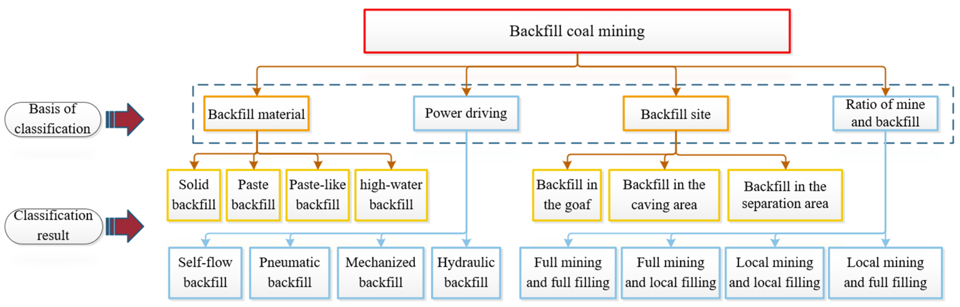
Figure 2.
New concepts for classifying backfill coal mining methods.
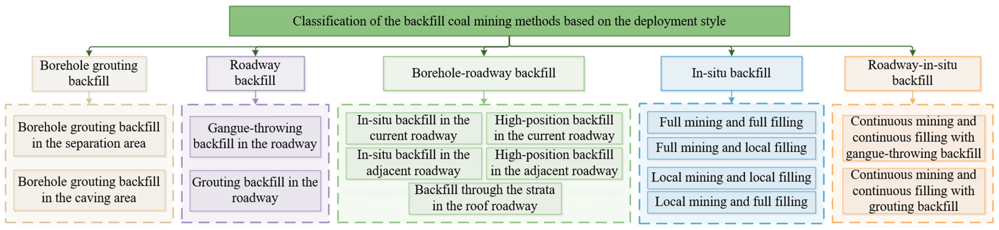
Figure 3.
Deployment of the borehole grouting backfill system. (a) Borehole grouting backfill in the separation area. (b) Borehole grouting backfill in the caving area.
Figure 3.
Deployment of the borehole grouting backfill system. (a) Borehole grouting backfill in the separation area. (b) Borehole grouting backfill in the caving area.
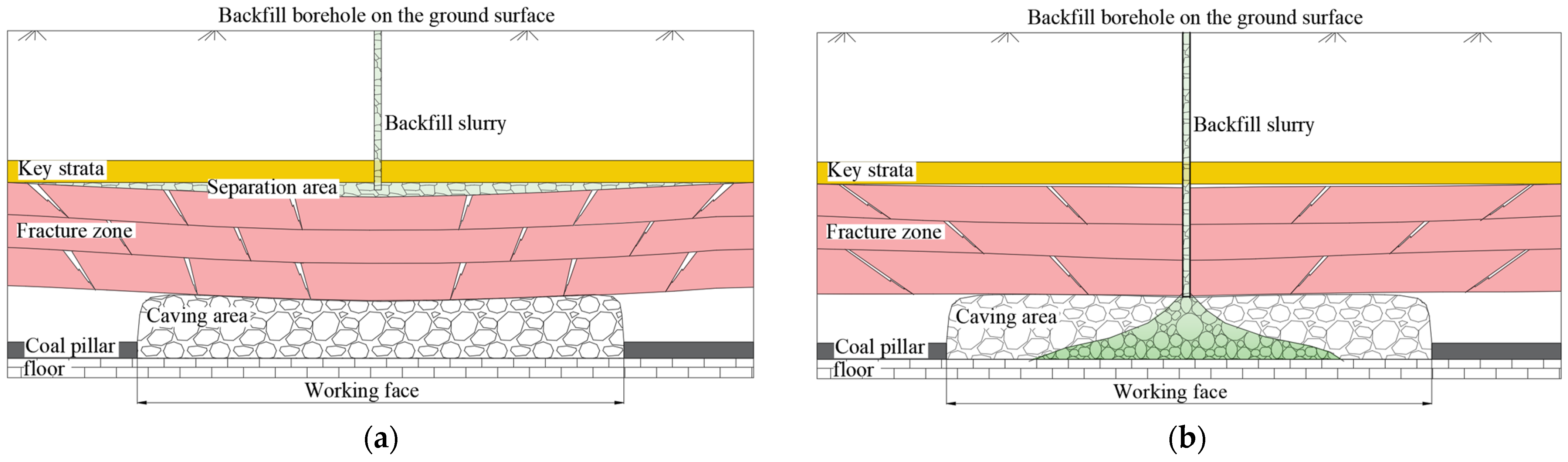
Figure 4.
Deployment of the roadway backfill system. (a) Gangue-throwing and filling in the roadway. (b) A-A cross-section. (c) Grouting backfill in the roadway. (d) B-B cross-section.
Figure 4.
Deployment of the roadway backfill system. (a) Gangue-throwing and filling in the roadway. (b) A-A cross-section. (c) Grouting backfill in the roadway. (d) B-B cross-section.
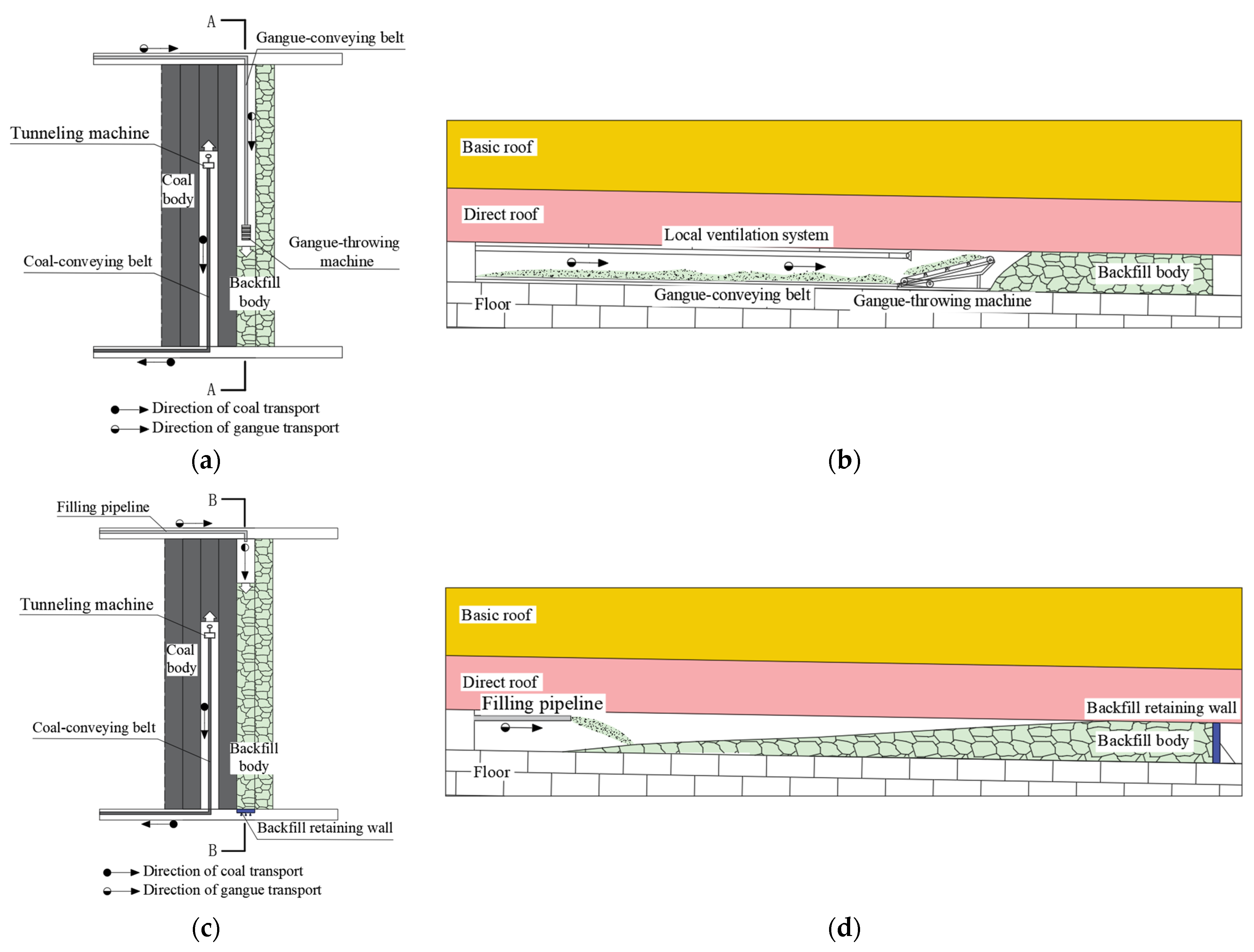
Figure 5.
Deployment of the roadway–borehole backfill system. (a) In situ backfill in the current roadway. (b) C-C cross-section. (c) High-position backfill in the current roadway. (d) D-D cross-section. (e) In-situ backfill in the adjacent roadway. (f) E-E cross-section. (g) High-position backfill in the adjacent roadway. (h) F-F cross-section. (i) Backfill through the strata in the roof roadway. (j) G-G cross-section.
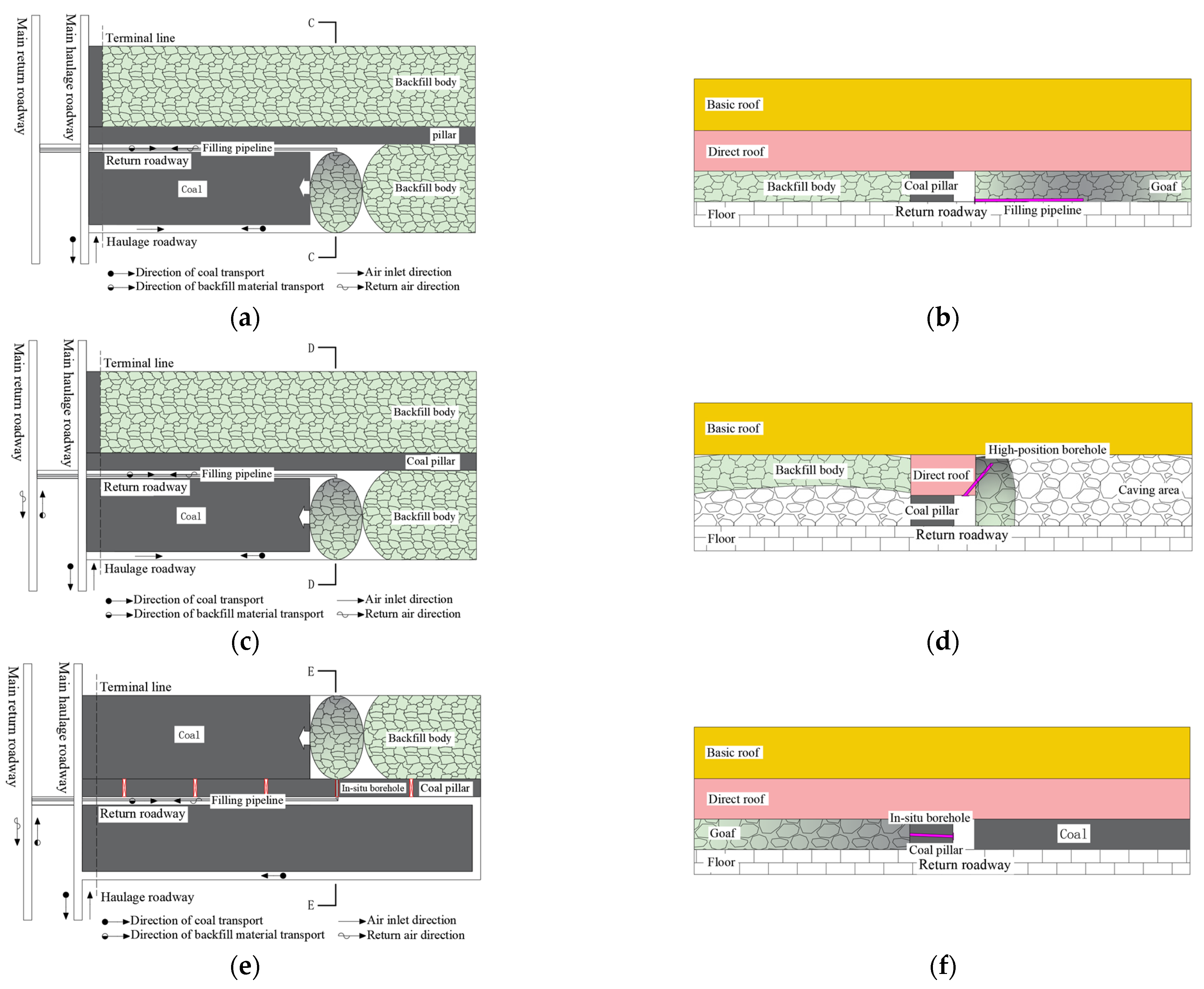
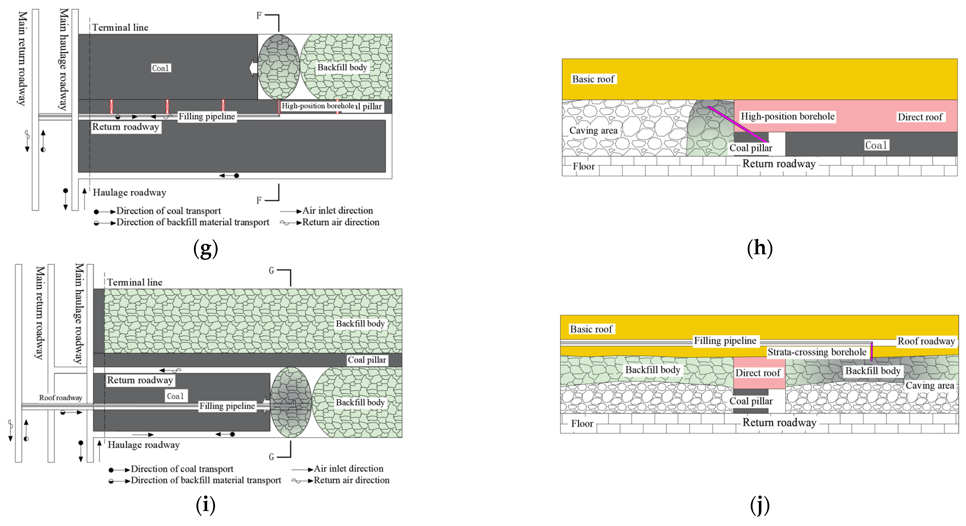
Figure 6.
Deployment of the in situ backfill system. (a) Full mining and full filling (FM + FF). (b) H-H cross-section. (c) Full mining and local filling (FM + LF). (d) I-I cross-section. (e) Local mining and local filling (LM + LF). (f) J-J cross-section. (g) Local mining and full filling (LM + FF). (h) K-K cross-section.
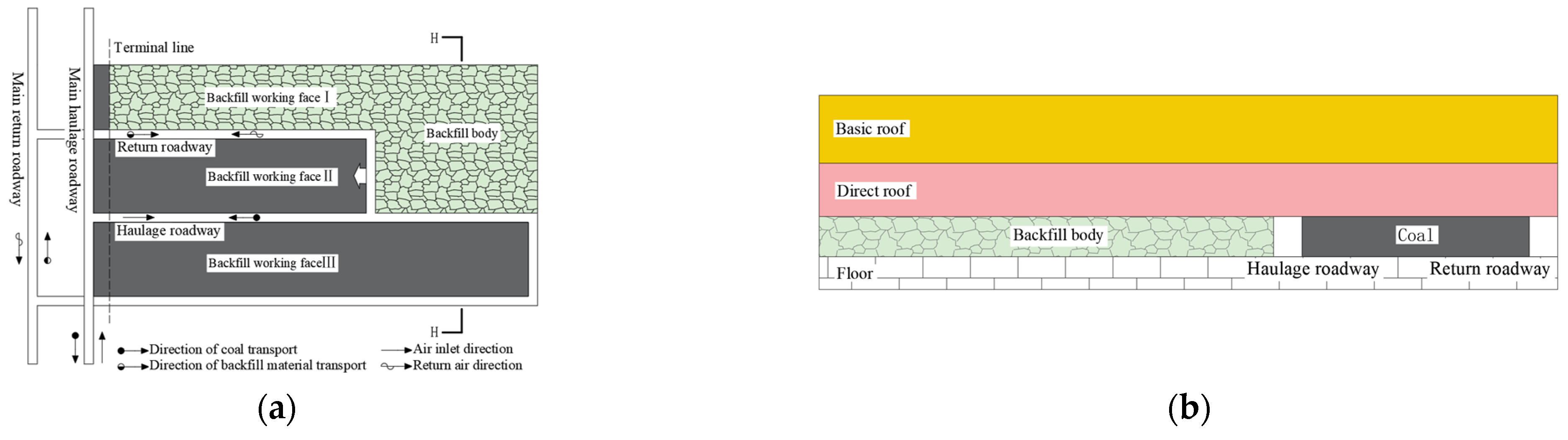

Figure 7.
A filling diagram for solid and paste backfill working face. (a) Solid backfill working face. (b) Paste backfill working face.
Figure 7.
A filling diagram for solid and paste backfill working face. (a) Solid backfill working face. (b) Paste backfill working face.
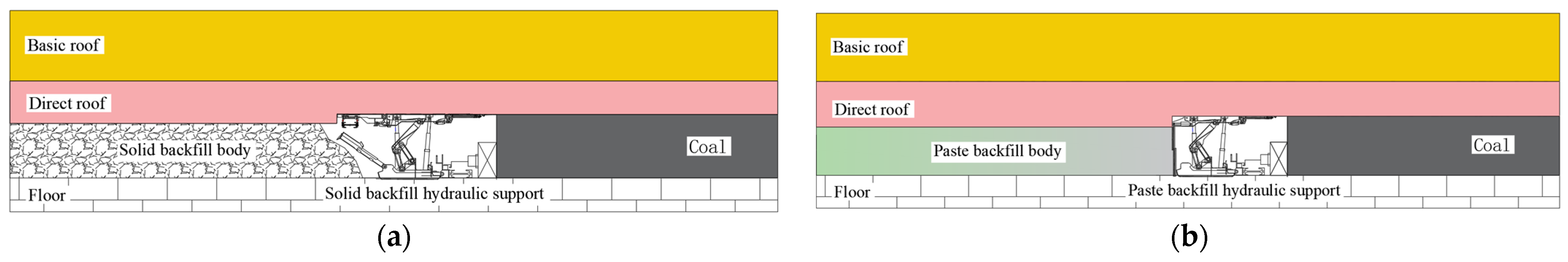
Figure 8.
Deployment of the in situ roadway backfill system. (a) Division of the mining segments. (b) Mining operation in the No. 1 branch roadway in segments Ⅰ and Ⅱ. (c) Parallel mining and filling operations in the No. 1 branch roadway of segments Ⅰ, Ⅱ, and Ⅲ. (d) Mining operation in the No. 3 branch roadway of segments Ⅰ and Ⅱ. (e) Parallel mining and filling operations in the No. 3 branch roadway of segments Ⅰ, Ⅱ, and Ⅲ. (f) Parallel mining and filling operations in the No. 2 branch roadway of segments Ⅰ, Ⅱ, and Ⅲ. (g) Parallel mining and filling operations in the No. 4 branch roadway of segments Ⅰ, Ⅱ, and Ⅲ. (h) The mining and filling operations in the branch roadways of N segments completed.


Figure 9.
Engineering design workflow for backfill coal mining.
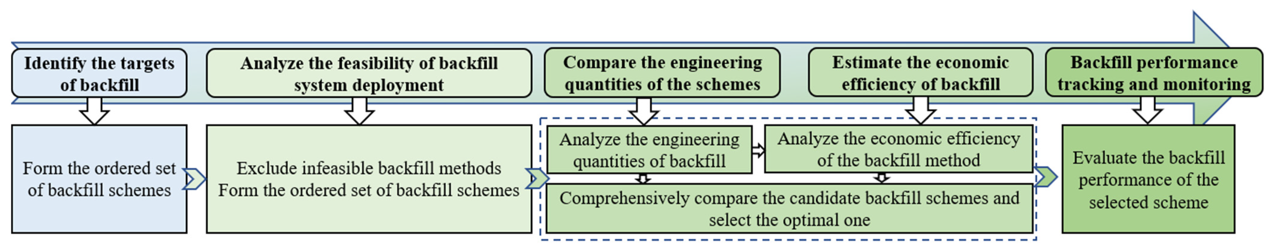
Figure 10.
The deployment of the backfill system in Xingdong Coal Mine.
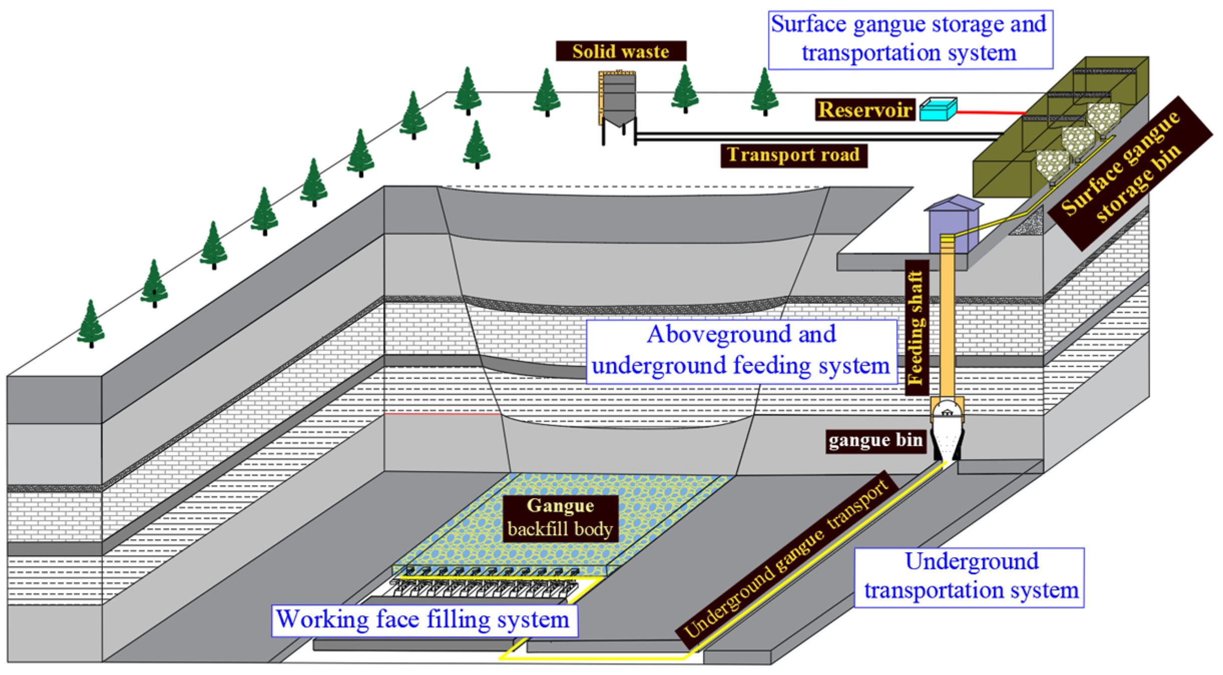
Figure 11.
The deployment of the backfill system in Bailongshan Coal Mine.

Table 1.
Survey results on backfill coal mining engineering cases.
| Serial Number | Coal Mine | Backfill Background | Mining Height /Meter | Type of the Mining Process | Deployment of the Backfill System |
|---|---|---|---|---|---|
| 1 | Xingdong Coal Mine | Mining under buildings | 4.6 | Fully-mechanized coal mining | 1. Gangue storage and transport above the ground; 2. Vertical feeding; 3. Underground transport; 4. Solid compaction and filling in the working face |
| 2 | Weijiadi Coal Mine | Recycled use of coal gangue | 14.3 | Fully-mechanized coal caving | 1. Prepare the slurry above the ground using gangue as the main raw material; 2. Grout in the caving area through the gas extraction hole on the ground. |
| 3 | Hongqinghe Coal Mine | Recycled use of coal gangue | 5.7 | Fully-mechanized coal mining | 1. Prepare slurry above the ground; 2. Drill a grouting borehole; |
| 4 | Xuchang Coal Mine | Coal pillar recycling in strip mining | 4.9 | Roadway mining | 1. Gangue crushing and transport; 2. Gangue-throwing backfill in the roadway |
| 5 | Gucheng Coal Mine | Mining under buildings | 6.0 | Fully-mechanized coal mining | 1. Gangue crushing, storage, and transport above the ground; 2. Vertical feeding; 3. Underground transport; 4. Solid backfill in the working face |
| 6 | Huangling No. 2 Coal Mine | Greening and emissions reduction through recycled use of coal gangue | 3.12 | Fully-mechanized coal mining | 1. Prepare the slurry above the ground; 2. Transport via pipelines; 3. Drill a grouting borehole in the adjacent position; 4. Grout the caving area |
| 7 | Yangliu Coal Mine | Mining under buildings | 3.0 | Fully-mechanized coal mining | 1. Prepare the slurry above the ground; 2. Drill a grouting borehole; |
| 8 | Bailongshan Coal Mine | Mining under the conservation area | 1.8 | Fully-mechanized coal mining | 1. Prepare the slurry above the ground; 2. Drill a grouting borehole in the high-position gas extraction roadway; 4. Grout the caving area |
| 9 | A coal mine in Shanxi | Greening and emissions reduction through recycled use of coal gangue | 4.0 | Fully-mechanized coal mining | 1. Prepare the slurry above the ground; 2. Transport the slurry via pipelines; |
| 10 | Mahuangliang Coal Mine | Mining under buildings | 3.5 | Roadway mining | 1. Prepare the slurry; 2. Transport the slurry by pumping; 3. Continuous mining and continuous filling in the four-stage working face |
| 11 | Taoyi Coal Mine | Mining under buildings | 4.0 | Fully-mechanized coal mining | 1. Transport the backfill material; 2. Prepare the slurry by mixing; 3. Bag-type filling of the high-water backfill |
| 12 | A coal mine in Northern Shaanxi | Coal pillar recycling | 3.5 | Roadway mining | 1. Prepare and transport the paste backfill by pumping; 2. Grouting backfill in the roadway |
Table 2.
Technical performance analysis of backfill coal mining methods and conditions for system deployment.
Table 2.
Technical performance analysis of backfill coal mining methods and conditions for system deployment.
| Classification of the Backfill Coal Mining Methods Based on the Deployment Style | Performance Analysis | Conditions for System Deployment | |
|---|---|---|---|
| Borehole grouting backfill | Borehole grouting backfill in the separation area | 1. High backfill performance but poor stability; 2. Poor solid waste treatment ability | 1. Land available for expropriation 2. Suitable for borehole drilling on the ground; 3. The presence and stability of the grouting space |
| Borehole grouting backfill in the caving area | |||
| Roadway backfill | Gangue-throwing backfill in the roadway | 1. High backfill performance but poor stability; 2. High solid waste disposal ability | 1. The coal seal thickness is not larger than the height of the extraction roadway; 2. The roadway has a dip angle; 3. The roadway space is intact and stable |
| Grouting backfill in the roadway | 1. High backfill performance and stability; 2. Poor solid waste disposal ability | ||
| Roadway-borehole backfill | In situ backfill in the current roadway | 1. Poor backfill performance and stability 2. Poor solid waste disposal ability | 1. Proper backfill roadway; 2. Suitable for borehole drilling in the roof |
| High-position backfill in the current roadway | |||
| In situ backfill in the adjacent roadway | |||
| High-position backfill in the adjacent roadway | |||
| Backfill through the strata in the roof roadway | |||
| In situ backfill | Full mining and full filling (FM + FF) | 1. High backfill performance and stability; 2. High solid waste disposal ability; 3. Applicable for recycling residual coal pillars | 1. The mining thickness should not be too large; 2. Applicable for recycling residual coal pillars |
| Full mining and local filling (FM + LF) | |||
| Local mining and local filling (LM + LF) | |||
| Local mining and full filling (LM + FF) | |||
| In situ Roadway backfill | Continuous mining and continuous filling with gangue-throwing backfill | 1. High backfill performance but poor stability; 2. High solid waste disposal ability | 1. The coal seal thickness is not larger than the height of the extraction roadway; 2. The roadway has a dip angle; 3. The roadway space is intact and stable; 4. Reasonable succession of mining and filling |
| Continuous mining and continuous filling with grouting backfill | 1. High backfill performance and stability; 2. Poor solid waste disposal ability | ||
Table 3.
Analysis of the engineering quantity of different backfill coal mining methods.
| Classification of the Backfill Coal Mining Methods Based on the Deployment Style | Engineering Quantity Analysis | |||
|---|---|---|---|---|
| Construction Quantity | Newly Added Equipment | Transport Pipelines | ||
| Borehole grouting backfill | Borehole grouting backfill in the separation area | Slurry preparation station and surface borehole drilling | Slurry preparation equipment, slurry transport pipelines, and backfill pump | Surface transport |
| Borehole grouting backfill in the caving area | ||||
| Roadway backfill | Gangue-throwing backfill in the roadway | None | Belt conveyor, gangue-throwing machine, etc. | Roadway transport |
| Grouting backfill in the roadway | Slurry preparation station, backfill retaining wall, etc. | Slurry preparation equipment, slurry transport pipelines, and backfill pump | Surface, aboveground and underground, and roadway transport | |
| Roadway-borehole backfill | In situ backfill in the current roadway | Slurry preparation station, grouting borehole, etc. | Slurry preparation equipment, slurry transport pipelines, and backfill pump | Surface, aboveground and underground, and roadway transport |
| High-position backfill in the current roadway | ||||
| In situ backfill in the adjacent roadway | ||||
| High-position backfill in the adjacent roadway | ||||
| Backfill through the strata in the roof roadway | ||||
| In situ backfill | Full mining and full filling (FM + FF) | Crushing station or slurry preparation station | Backfill supports, belt conveyor, or slurry transport pipeline | Surface, aboveground and underground, and roadway transport, and transport in the working face |
| Full mining and local filling (FM + LF) | ||||
| Local mining and local filling (LM + LF) | ||||
| Local mining and full filling (LM + FF) | ||||
| In situ roadway backfill | Continuous mining and continuous filling with gangue-throwing backfill | None | Belt conveyor, gangue-throwing machine, etc. | Roadway transport |
| Continuous mining and continuous filling with grouting backfill | Slurry preparation station, backfill retaining wall, etc. | Slurry preparation equipment, slurry transport pipelines, and backfill pump | Surface, aboveground and underground, and roadway transport | |
Disclaimer/Publisher’s Note: The statements, opinions and data contained in all publications are solely those of the individual author(s) and contributor(s) and not of MDPI and/or the editor(s). MDPI and/or the editor(s) disclaim responsibility for any injury to people or property resulting from any ideas, methods, instructions or products referred to in the content. |
© 2023 by the authors. Licensee MDPI, Basel, Switzerland. This article is an open access article distributed under the terms and conditions of the Creative Commons Attribution (CC BY) license (https://creativecommons.org/licenses/by/4.0/).
Share and Cite
MDPI and ACS Style
Cui, P.; Zhang, Q.; Yang, K.; Lv, H.; Cao, J.; Wang, W. Classification and Design of Backfill Coal Mining Systems Based on Typical Engineering Cases. Energies 2023, 16, 8074. https://doi.org/10.3390/en16248074
AMA Style
Cui P, Zhang Q, Yang K, Lv H, Cao J, Wang W. Classification and Design of Backfill Coal Mining Systems Based on Typical Engineering Cases. Energies. 2023; 16(24):8074. https://doi.org/10.3390/en16248074
Chicago/Turabian StyleCui, Pengfei, Qiang Zhang, Kang Yang, Haonan Lv, Jinming Cao, and Wei Wang. 2023. "Classification and Design of Backfill Coal Mining Systems Based on Typical Engineering Cases" Energies 16, no. 24: 8074. https://doi.org/10.3390/en16248074
Note that from the first issue of 2016, this journal uses article numbers instead of page numbers. See further details here.